

Page 1

Asterion Series User Manual – 14U Models California Instruments
Asterion Series
AC/DC Power Source
14U Models
User Manual
M330511-01, REV-B 1
Page 2

Page 3

Asterion Series User Manual – 14U Models California Instruments
Telephone:
800 733 5427 (toll free in North America)
858 450 0085 (direct)
Fax:
858 458 0267
Email:
sales.ppd@ametek.com
service.ppd@ametek.com
Web:
www.programmablepower.com
About AMETEK
AMETEK Programmable Power, Inc., a Division of AMETEK, Inc., is a global leader in the design and
manufacture of precision, programmable power supplies for R&D, test and measurement, process
control, power bus simulation and power conditio ni ng applications across diverse industrial segments.
From bench top supplies to rack mounted industrial power subsystems, AMETEK Programmable Po wer
is the proud manufacturer of VTI, Elgar, Sorensen, California Instruments, Amrel brand power supplies.
AMETEK, Inc. is a leading global manufacturer of el ectronic instruments and electromechani cal devices
with annualized sales of $5 billion. The Company has over 18,000 colleagues working at nearly 150
manufacturing facilities and nearly 150 sales and service centers in the United States and 30 other
countries around the world.
Trademarks
AMETEK is a registered trademark of AMETEK, Inc. California Instruments is a trademark owned by
AMETEK, Inc. Other trademarks, registered trademarks, and product names are the property of t hei r
respective owners and are used herein for identification purposes only.
Notice of Copyright
Asterion Series User Manual © 2019 AMETEK Programmable Power, Inc. All rights reserved.
Exclusion for Documentation
UNLESS SPECIFICALLY AGREED TO IN WRITING, AMETEK PROGRAMMABLE POWER, INC . (“AMETEK”):
(a) MAKES NO WARRANTY AS TO THE ACCURACY, SUFFICIENCY OR SUITABILITY OF ANY TECHNICAL
OR OTHER INFORMATION PROVIDED IN ITS MANUALS OR OTHER DOCUMENTATION.
(b) ASSUMES NO RESPONSIBILITY OR LIABILITY FOR LOSSES, DAMAGES, COSTS OR EXPENSES,
WHETHER SPECIAL, DIRECT, INDIRECT, CONSEQUENTIAL OR INCIDENTAL, WHICH MIGHT ARISE
OUT OF THE USE OF SUCH INFORMATION. THE USE OF ANY SUCH INFORMATION WILL BE
ENTIRELY AT THE USER’S RIS K, AND
(c) GIVES NOTIFICATION THAT, IF THIS MANUAL IS IN ANY LANGUAGE OTHER THAN ENGLISH,
ALTHOUGH STEPS HAVE BEEN TAKEN TO MAINTAIN THE ACCURACY OF THE TRANSLATION, THE
ACCURACY CANNOT BE GUARANTEED. APPROVED AMETEK CONTENT IS WITHIN THE ENGLISH
LANGUAGE VERSION, WHICH I S POSTED AT WWW.PROGRAMMABLEPOWER.COM.
Part Number
M330511-01
Revision and Date
Revision B, October 2019
Contact Information
M330511-01, REV-B 3
Page 4
Important Safety Instructions
Before applying power to the system, verify that your product is configured properly for your application.
Hazardous voltages may be present when covers are removed. Qualified
personnel must use extreme caution when servicing this equipment.
Circuit boards, test points, and output voltages also may be floating at a
WARNING
WARNING
Only qualified personnel, who deal with attendant hazards in power supplies, are allowed to perform
installation and servicing.
Ensure that the AC input power line ground is connected properly to the unit safety ground chassis.
Similarly, other AC power ground lines, including those to application and maintenance equipment, must
be grounded properly for both personnel safety and equipment protection.
Always ensure that facility AC input power is de-energized prior to connecting or disconnecting any cable.
In normal operation, the operator does not have ac cess to hazardous voltages within the chassis.
However, depending on the user’s application configuration, HIGH VOLTAGES HAZARDOUS TO
HUMAN SAFETY may be normally generat ed on the output terminals. The customer/user must ensure
that the output power lines are labeled properly a s t o the safety hazards and that any inadvertent conta ct
with hazardous voltages is prevented.
Guard against risks of electrical shock during open cover checks by not touching any portion of the
electrical circuits. Even when power is off, capacitors may retain an electrical charge. Use safety glasses
and protective clothing during open cover checks to avoid personal injury by any sudden component
failure.
AMETEK Programmable Power Inc., San Diego, California, USA, or any of the subsidiary sales
organizations, cannot accept any responsibility for personnel, material or inconsequential injury, loss or
damage that results from improper use of the equipm ent and accessories.
high voltage relative to chassis ground.
The equipment used contains ESD sensitive parts. When installing
equipment, follow ESD Safety Procedures. Electrostatic discharges might
cause damage to the equipment.
Safety Symbols
Product: Asterion Series Power Source
Page 5

Asterion Series User Manual – 14U Models California Instruments
Warranty Period: 1 Year
Warranty Terms
AMETEK Programmable Power, Inc. (“AMETE K”), provides this written warranty covering the P roduct
stated above, and if the Buyer discovers and notifies AMETEK in writing of any defect in material or
workmanship within the applicable warranty period st ated above, then AMETEK may, at its option: repair
or replace the Product; or issue a credit note for the defective Product; or provide the Buyer with
replacement parts for the Product.
The Buyer will, at its expense, return the defective P roduct or parts thereof to AMETEK in accordance
with the return procedure specified below. AMETEK will, at its expense, deliver the repaired or repla ced
Product or parts to the Buyer. Any warranty of AMETEK will not apply if the Buyer is in default under the
Purchase Order Agreement or where the Product, or any part thereof, is as follows:
• damaged by misuse, accident, negligence or failure to maintain the same as specified or
required by AMETEK;
• damaged by modifications, alterations or attachments thereto which are not authorized by
AMETEK;
• installed or operated contrary to the instructions of AMETEK;
• opened, modified, or disassembled in any way without AMETEK’s consent;
• used in combination with items, articles or materials not authorized by AMETEK.
The Buyer may not assert any claim that the Products are not in conformity with any warranty until the
Buyer has made all payments to AMETEK provided for in the Purchase Order Agreement.
Product Return Procedure
Request a Return Material Authorization (RMA) number from the repair facility (must be done in the
country in which it was purchased):
• In the USA, contact the AMETEK Customer Service Department prior to the return of the
product to AMETEK for repair:
Telephone: 800-733-5427, ext. 2295 or ext. 2463 (toll free North America)
858-450-0085, ext. 2295 or ext. 2463 (direct)
• Outside the United States, contact the nearest Authorized Service Center (ASC). A full
listing can be found either through your local distributor, or on our website,
www.programmablepower.com, by tapping Support button or going to the Service Centers
tab.
When requesting an RMA, have the following information ready:
• Model number
• Serial number
• Description of the problem
NOTE: Unauthorized returns will not be accepted and will be returned at the shipper’s expense.
NOTE: A returned product found upon inspection by AMETEK to be in specification is subject to an
evaluation fee and applicable freight charges.
M330511-01, REV-B 5
Page 6

Table of Contents
1. Introduction................................................................................................................................. 13
1.1 General Description ............................................................................................................................. 14
1.2 Asterion Series Models ....................................................................................................................... 15
2. Specifications ............................................................................................................................. 17
2.1 Electrical Characteristics ..................................................................................................................... 17
2.1.1 AC/DC Output Specifications .................................................................................................. 17
2.1.2 iX2TM Constant-Power Mode Output Characteristic ................................................................ 19
2.1.3 AC Input Specifications ........................................................................................................... 20
2.1.4 AC Output Measurements....................................................................................................... 22
2.1.5 DC Output Measurements ...................................................................................................... 23
2.1.6 Harmonics Measurements ...................................................................................................... 24
2.1.7 Protection Function Characteris tics ........................................................................................ 24
2.2 Regulatory Agency Compliance .......................................................................................................... 25
2.3 Environmental Specifications .............................................................................................................. 25
2.4 Mechanical Specifications ................................................................................................................... 26
2.5 Remote Control Digital Interfa c e C haracteristics ................................................................................. 26
2.6 Remote Control Analog/Digital Signal Characteristics ......................................................................... 27
2.7 Operational Characteristics ................................................................................................................. 28
2.8 Front Panel Controls/Indicators ........................................................................................................... 29
2.9 Rear Panel Connectors ....................................................................................................................... 30
2.10 Firmware/Software Options ................................................................................................................. 31
3. Installation................................................................................................................................... 33
3.1 Unpacking ........................................................................................................................................... 33
3.1.1 Contents of Shipment ............................................................................................................. 33
3.2 Mechanical Installation ........................................................................................................................ 34
3.2.1 Handling .................................................................................................................................. 34
3.2.2 Rackmounting ......................................................................................................................... 36
3.3 Outline Drawings ................................................................................................................................. 38
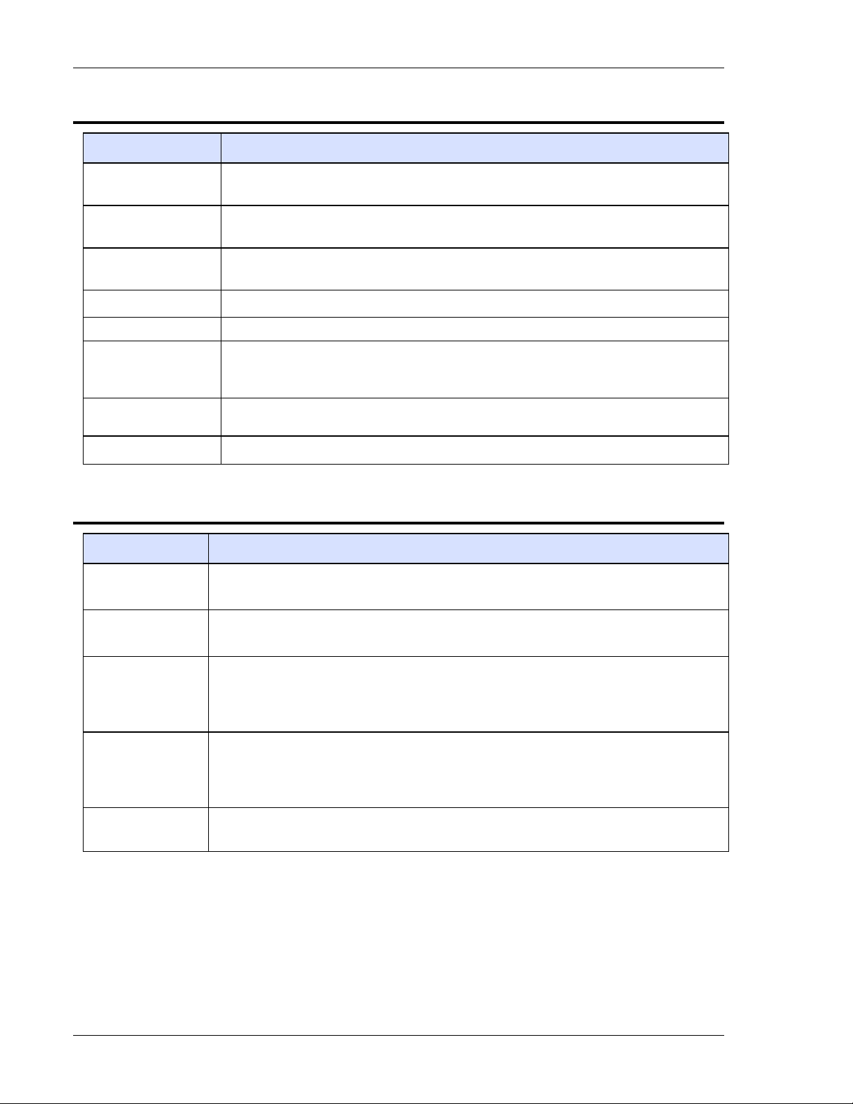
3.4 Rear Panel Protective Covers ............................................................................................................. 38
3.5 Input/output Connections .................................................................................................................... 42
3.6 AC Input Connection ........................................................................................................................... 43
3.6.1 AC Input Overcurrent Protection ............................................................................................. 43
3.6.2 AC Input Safety Disconnect Device ........................................................................................ 44
3.6.3 AC Input Connector ................................................................................................................ 44
3.7 AC/DC Output Connection .................................................................................................................. 47
3.7.1 Output Connection for 3-Phase Load ...................................................................................... 48
3.7.2 Output Connection for 1-Phase Load ...................................................................................... 49
3.8 Remote Sense Connection.................................................................................................................. 50
3.9 Remote Sense ..................................................................................................................................... 51
3.10 Noise and Impedance Effects .............................................................................................................. 51
3.11 Wire Gauge Selection ......................................................................................................................... 52
3.11.1 Wire Size............................................................................................................................... 52
3.12 Rear Panel User Interface Connectors ................................................................................................ 54
3.12.1 External Input/Output Control Signal Connector ................................................................... 54
3.12.2 Summary Fault Signal (DFI) .................................................................................................. 57
3.12.3 Remote Inhibit Signal ............................................................................................................ 57
3.12.4 External Relay Interface ........................................................................................................ 58
3.12.5 External Interface Signal Connector ..................................................................................... 59
3.12.6 Command Monitor and Trigger Output Connectors .............................................................. 60
3.12.7 Clock and Lock Connectors (Option) .................................................................................... 60
3.12.8 Master/Auxiliary System Int erface Connectors ..................................................................... 61
3.12.9 RS-232C Serial Interface Connector ..................................................................................... 62
3.12.10 USB Interface ...................................................................................................................... 63
3.12.11 LAN Interface (Ethernet) ..................................................................................................... 64
3.13 Multiple Chassis System Configurations ............................................................................................. 65
3.13.1 Multi-Phase System .............................................................................................................. 65
3.13.2 Parallel System ..................................................................................................................... 65
Page 7

Asterion Series User Manual – 14U Models California Instruments
4. Operation .................................................................................................................................... 69
4.1 Front Panel Operation ......................................................................................................................... 69
4.1.1 Front Panel Controls and Indicator s, Enhanced Models ......................................................... 70
4.1.2 Front Panel Controls and Indicator s ATE Models ................................................................... 71
4.2 Basic Output Programming .................................................................................................................. 73
4.2.1 Front Panel Display Navigation ............................................................................................... 73
4.2.2 Selecting Output Characteristics and Adjusting Parameters ................................................... 73
4.3 Basic Functional Test .......................................................................................................................... 74
4.4 Output Power Characteristic ................................................................................................................ 75
4.5 Front Panel Touch-Screen Display ...................................................................................................... 76
4.5.1 Touch-Screen Numeric Keypad .............................................................................................. 77
4.5.2 Rotary Encoder ....................................................................................................................... 77
4.6 Front Panel Display Menus .................................................................................................................. 80
4.6.1 DASHBOARD Screen Top-Level Menu .................................................................................. 82
4.6.2 OUTPUT PROGRAM Screen Top Level Menus ..................................................................... 84
4.6.3 MEASUREMENTS Screen Top-Level Menus ......................................................................... 89
4.6.4 TRANSIENTS Screen Top-Level Menu .................................................................................. 95
4.6.5 CONFIGURATION Screen .................................................................................................... 111
4.6.6 CONTROL INTERFACE Screen ........................................................................................... 119
4.6.7 PROTECTION Screen .......................................................................................................... 124
4.6.8 APPLICATIONS Screen ........................................................................................................ 125
4.6.9 SYSTEM SETTINGS Screen ................................................................................................ 126
5. Waveform Management ........................................................................................................... 129
5.1 Standard Waveforms ......................................................................................................................... 129
5.2 Creating Custom Waveforms ............................................................................................................. 129
5.2.1 Viewing Custom Waveforms on the Display .......................................................................... 130
5.3 RMS Amplitude Restrictions .............................................................................................................. 130
5.4 Frequency Response Restrictions ..................................................................................................... 131
5.5 Transient List Waveforms .................................................................................................................. 131
6. Standard Measurements ......................................................................................................... 133
6.1 Parameter Measurements ................................................................................................................. 133
6.1.1 Accuracy Considerations ....................................................................................................... 134
6.2 Advanced Measurements .................................................................................................................. 134
6.2.1 Harmonic Analysis................................................................................................................. 134
6.2.2 Acquiring FFT data ................................................................................................................ 134
6.2.3 Analyzing FFT Data............................................................................................................... 135
6.3 Triggering Measurements .................................................................................................................. 136
6.3.1 Trigger Mode ......................................................................................................................... 136
6.3.2 Trigger source ....................................................................................................................... 136
6.3.3 Trigger delay ......................................................................................................................... 137
7. Transient Programming .......................................................................................................... 139
7.1 Using Transient Modes ...................................................................................................................... 139
7.1.1 Step Transients ..................................................................................................................... 140
7.1.2 Pulse Transients ................................................................................................................... 140
7.1.3 List Transients ....................................................................................................................... 141
7.2 Programming Slew Rates .................................................................................................................. 142
7.3 Switching Waveforms in Transient Li s ts ............................................................................................ 143
7.4 Saving Transient List Programs ......................................................................................................... 144
8. Calibration ................................................................................................................................ 145
8.1 Calibration Equipment ....................................................................................................................... 145
8.2 Calibration Procedures ...................................................................................................................... 145
8.2.1 Preparation for Calibration .................................................................................................... 145
8.2.2 Output Voltage AC Zero Alignment, A C-Mode ...................................................................... 146
8.2.3 Output Voltage DC Zero Alignment , DC-Mode ...................................................................... 146
8.2.4 Output Voltage Gain Initial Alignment, AC-Mode and DC-Mode ........................................... 147
8.2.5 Output Voltage Measurement AC Gain A lignment, AC-Mode ............................................... 148
M330511-01, REV-B 7
Page 8

8.2.6 Output Voltage Measurement DC-Posi tive Gain Alignment, DC-Mode ................................. 148
8.2.7 Output Voltage Measurement DC-Negat i ve Gain Alignment, DC-Mode ............................... 149
8.2.8 Output Current Measurement AC Low-Range Gain Alignment, AC-Mode ............................ 149
8.2.9 Output Current Measurement AC High-Range Gain Alignment, AC-Mode ........................... 150
8.2.10 Output Current Measurement AC Low-Range Offset Alignment, AC-Mode ........................ 151
8.2.11 Output Current Measurement AC High-Range Offset Alignment, AC-Mode ....................... 151
8.2.12 Output Current Measurement DC-P os i tive Low-Range Gain Alignment, DC-Mode ............ 152
8.2.13 Output Current Measurement DC-Positive High-Range Gain Alignment, DC-Mode ........... 152
8.2.14 Output Current Measurement DC-Negative Low-Range Gain Alignment, DC-Mode .......... 153
8.2.15 Output Current Measurement DC-Negative High-Range Gain Alignment, DC-Mode ......... 153
8.2.16 Output Current Measurement Low-Range Offset Alignment, DC-Mode ............................. 154
8.2.17 Output Current Measurement High-Range Offset Alignment, DC-Mode ............................. 155
8.2.18 Output Phase-A Alignment, Out put Relative to External SYNC .......................................... 156
8.2.19 Output Phase-A Alignment, Auxiliary Unit Relative to Master Unit (LKS Option Only) ........ 156
8.2.20 Output Phase-B and Phase-C Alignm ent Relative to Phase-A ........................................... 157
8.2.21 Alignment of External Program m i ng S ignal for Output Voltage Waveform/Amplitude ........ 158
8.2.22 Alignment of External Program m i ng S ignal for Output Voltage Amplitude, DC Output ....... 159
8.2.23 Alignment of External Program m i ng S ignal for Output Voltage Amplitude, AC output ........ 160
9. Service ....................................................................................................................................... 163
9.1 Cleaning ............................................................................................................................................ 163
9.2 Basic Troubleshooting ....................................................................................................................... 163
9.2.1 Excessive Output Voltage ..................................................................................................... 163
9.2.2 Poor Output Voltage Regulation ........................................................................................... 163
9.2.3 FAULT LED is On ................................................................................................................. 163
9.2.4 Distorted Output .................................................................................................................... 164
9.2.5 Unit Shuts Down after Short Interval ..................................................................................... 164
9.2.6 No Output and Front Panel Display/LEDs are Off ................................................................. 164
9.2.7 No Output and Front Panel Display/LEDs are On ................................................................. 164
9.2.8 Setting of AC/DC Mode or Voltage Range is Not Accepted .................................................. 164
9.2.9 Parallel Group Faults When Master Output Switch is Turned On ......................................... 164
10. Error and Status Messages ..................................................................................................... 165
Index ................................................................................................................................................. 171
Page 9

Asterion Series User Manual – 14U Models California Instruments
List of Figures
Figure 1-1. 14U-Asterion Series Front View ........................................................................................................ 13
Figure 2-1. iX2TM Constant-Power: Output Current Versus Voltage, AST 12K3 and AST18K 3 ........................... 19
Figure 3-1. Shipping Strap Installation ................................................................................................................. 35
Figure 3-2. Rackmounting Install ation ................................................................................................................. 36
Figure 3-3. Rackmount Kit Installat ion (Option) ................................................................................................... 37
Figure 3-4. Rear Panel Output Sense P rotective Cover Installation .................................................................... 38
Figure 3-5. Rear Panel Input/Output Protective Cover Installation ...................................................................... 39
Figure 3-6. Installation Dra win g, Enhanced Model .............................................................................................. 40
Figure 3-7. Installation Dra win g ATE Models ...................................................................................................... 41
Figure 3-8. Rear Panel View (with GP IB and LKM/LKS options) ......................................................................... 42
Figure 3-9. AC Input Connector and Safety-Ground Stud, for 3-Wire plus Ground Input .................................... 44
Figure 3-10. AC Input Connector and Safety-Ground Stud, for 4-Wire (with Neutral) plus Ground Input ............ 45
Figure 3-11. AC/DC Output Connector and Functional-Ground .......................................................................... 47
Figure 3-12. Output Connection to 3-Ph ase Loa d ............................................................................................... 48
Figure 3-13. Output Connection to 1-Ph ase Loa d ............................................................................................... 49
Figure 3-14. Remote Sense Connect or and Functional-Ground ......................................................................... 50
Figure 3-15. External Input/Output C ontrol Connector ........................................................................................ 54
Figure 3-16. External Relay Interf ace Connector ................................................................................................. 58
Figure 3-17. External Relay Interf ace for 1-Phase Relay Control ........................................................................ 59
Figure 3-18. External Interface Signal Connector ................................................................................................ 59
Figure 3-19. External Command Monitor and Trigger Output Connectors .......................................................... 60
Figure 3-20. External Clock/Lock Interface Connectors (Option) ......................................................................... 60
Figure 3-21. External Master/Auxiliary System Interface Connector s .................................................................. 61
Figure 3-22. RS-232C Interface Connector ......................................................................................................... 62
Figure 3-23. USB Interface Connector ................................................................................................................ 63
Figure 3-24. LAN Interface 8P8C Modular Connector ......................................................................................... 64
Figure 3-25. Connections for 3-Phase Parallel Group ......................................................................................... 67
Figure 3-26. Connections for 3-Phase Master/Auxiliary Multi-P hase Group ........................................................ 68
Figure 4-1. Front Panel, Enhanced Mo del s ......................................................................................................... 69
Figure 4-2. Front Panel, ATE Models .................................................................................................................. 71
Figure 4-3. iX2TM Constant-Power Output Characteristic .................................................................................... 75
Figure 4-4. HOME Screen ................................................................................................................................... 76
Figure 4-5. DASHBOARD Screen Menu with Voltage Selection-Field Active ..................................................... 76
Figure 4-6. Menu with Only Phase-A Selected .................................................................................................... 77
Figure 4-7. Touch-Screen Numeric Keypad ........................................................................................................ 77
Figure 4-8. Rotary Encoder ................................................................................................................................. 78
Figure 4-9. Output Program Menu Selec tion-Fields with Phase Number Highlighted ......................................... 78
Figure 4-10. Highlighted Voltage Selection-Field with Value Window ................................................................. 79
Figure 4-11. Power-On Screens .......................................................................................................................... 80
Figure 4-12. HOME Screen ................................................................................................................................. 81
Figure 4-13. DASHBORD Screen Top-Lev el Menu ............................................................................................. 82
Figure 4-14. Real-Time, Immediate Output Parameter Adjustment ..................................................................... 83
Figure 4-15. Default Screen ................................................................................................................................ 84
Figure 4-16. OUTPUT PROGRAM Screen Top-Level Menu ............................................................................... 84
Figure 4-17. MEASUREMENTS Screen Top-Level Menu ................................................................................... 89
Figure 4-18. HARMONICS Menu ........................................................................................................................ 92
Figure 4-19. HARMONICS Menu, Table View ..................................................................................................... 94
Figure 4-20. HARMONICS Menu, Bar Gr aph View ............................................................................................. 94
Figure 4-21. TRANSIENTS Screen Top-Level Menu .......................................................................................... 95
Figure 4-22. SETTINGS Menu ............................................................................................................................ 95
Figure 4-23. SETTINGS Screen, TRIGGER Sub-Menu ...................................................................................... 97
Figure 4-24. VIEW Menu, With Empty Buffer ...................................................................................................... 98
Figure 4-25. VIEW Menu, With Transient List Entry ............................................................................................ 98
Figure 4-26. VIEW Menu, ADD Sub-Menu .......................................................................................................... 99
Figure 4-27. VIEW Menu, VOLTAG E DRO P Sub-Menu ................................................................................... 102
Figure 4-28. VIEW Menu, VOLTAGE SWEEP/STEP Sub-Menu ....................................................................... 103
Figure 4-29. VIEW Menu, VOLTAGE SURGE/SAG Sub-Menu......................................................................... 104
Figure 4-30. VIEW Menu, FREQUENCY SWEEP/STEP Sub-Menu ................................................................. 105
Figure 4-31. VIEW Menu, FREQUENCY SURGE/SAG Sub-Menu ................................................................... 106
Figure 4-32. VIEW Menu, VOLT/FREQ SWEEP/STEP Sub-Menu ................................................................... 107
M330511-01, REV-B 9
Page 10

Figure 4-33. VIEW Menu, VOLT/FREQ SURGE/SAG Sub-Menu ..................................................................... 108
Figure 4-34. VIEW Menu, DELAY Sub-Menu .................................................................................................... 109
Figure 4-35. RUN Menu .................................................................................................................................... 110
Figure 4-36. CONFIGURATION Scr een Top-Level Menu ................................................................................. 111
Figure 4-37. CONFIGURATION Menu, PROFILES Sub-Menu ......................................................................... 112
Figure 4-38. PROFILES Menu, NAME Sub-Menu ............................................................................................ 112
Figure 4-39. CONFIGURATION Menu, P ONS Menu-1/2 .................................................................................. 114
Figure 4-40. CONTROL INTERFACE Screen ................................................................................................... 119
Figure 4-41. CONTROL INTERFACE Menu, ANALOG Sub-Menu ................................................................... 120
Figure 4-42. CONTROL INTERFACE Menu, RS232 Sub-Menu ....................................................................... 120
Figure 4-43. CONTROL INTERFACE Menu, GPIB Sub-Menu ......................................................................... 121
Figure 4-44. CONTROL INTERFACE, LA N Menu ............................................................................................ 121
Figure 4-45. CONTROL INTERFACE, LAN CONFIGURE S ub-Menu .............................................................. 122
Figure 4-46. CONTROL INTERFACE REMOTE INHIBIT M enu ....................................................................... 124
Figure 4-47. PROTECTION Screen .................................................................................................................. 124
Figure 4-48. APPLICATIONS Screen, Output Impedance Example ................................................................. 125
Figure 4-49. SYSTEM SETTINGS Screen ........................................................................................................ 126
Figure 4-50. SYSTEM SETTINGS Menu, LC D Menu ....................................................................................... 127
Figure 5-1. HARMONICS Screen, Waveform Information ................................................................................. 130
Figure 6-1. HARMONICS Menu ........................................................................................................................ 134
Figure 6-2. FFT data in Tabular Format ............................................................................................................ 135
Figure 6-3. FFT data in Bar Graph Format ........................................................................................................ 135
Figure 6-4. HARMONICS Menu, Triggeri ng ...................................................................................................... 136
Figure 6-5. Post-Trigger (Positive D elay) .......................................................................................................... 137
Figure 6-6. Pre-Trigger (Negative Delay ........................................................................................................... 138
Figure 7-1. Output Transient Modes.................................................................................................................. 140
Figure 7-2. Pulse Transients ............................................................................................................................. 141
Figure 7-3. List Transients ................................................................................................................................. 141
Figure 7-4. Switching Waveforms i n a Transient List Transient Execution ........................................................ 143
Figure 7-5. RUN Menu: Start and Abort Fields .................................................................................................. 143
Figure 7-6. CONFIGURATION Menu, PROFILES S election ............................................................................. 144
Page 11

Asterion Series User Manual – 14U Models California Instruments
List of Tables
Table 3-1. Rackmount Kit Parts List (Option) ...................................................................................................... 38
Table 3-2. AC Input Connector Pinout and Safety-Ground, for 3-Wire plus Ground Input ................................... 45
Table 3-3. AC Input Connector Pinout and Safety-Ground, for 4-Wire (with Neutral) plus Ground Input ............ 46
Table 3-4. AC Input Connector Type ................................................................................................................... 46
Table 3-5. AC/DC Output Connector Pinout and Functional-Ground .................................................................. 47
Table 3-6. AC/DC Output Connector Type and Functional-Ground ..................................................................... 48
Table 3-7. Remote Sense Connector Pinout ....................................................................................................... 50
Table 3-8. Remote Sense Connector Type ......................................................................................................... 50
Table 3-9. Minimum Wire Size ............................................................................................................................. 52
Table 3-10. Wire Resistance and Voltage Drop, 20 °C ........................................................................................ 53
Table 3-11. External Input/Output Control Connector Type ................................................................................. 54
Table 3-12. External Input/Output Control Functions ........................................................................................... 55
Table 3-13. External Input/ Output Control Connector Pinout ............................................................................. 56
Table 3-14. External Relay Interface C onnector Type ......................................................................................... 58
Table 3-15. External relay interf ace Connector Pinout. ....................................................................................... 58
Table 3-16. External Interface Signal Connector Type ........................................................................................ 59
Table 3-17. External Command Monitor s and Trigger Output Characteristics .................................................... 60
Table 3-18. External Clock/Lock Interface Characteristics (Option) .................................................................... 61
Table 3-19. External Master/Auxili ary System Interface Connector Type ............................................................ 61
Table 3-20. External Master/Auxili ary System Interface Characteris tics ............................................................. 62
Table 3-21. RS-232C Interface Connector Type ................................................................................................. 62
Table 3-22. RS-232C Interface Connector Pinout ............................................................................................... 62
Table 3-23. USB Interface Connector P inout ...................................................................................................... 63
Table 3-24. LAN Interface 8P8C Modular Connector Pinout ............................................................................... 64
Table 4-1. Front Panel Controls and Indicators, Enhanced Models ..................................................................... 70
Table 4-2. Front Panel Controls and I ndicators, ATE Models .............................................................................. 72
Table 4-3. HOME Screen Menu Content ............................................................................................................. 81
Table 6-1. MEASUREMENTS Screen Parameters ........................................................................................... 133
Table 6-2. MEASUREMENTS Parameter Value Derivation .............................................................................. 133
Table 8-1. Calibration Equipment ...................................................................................................................... 145
Table 8-2. Load Values for Output AC Current Alignment ................................................................................. 155
Table 8-3. Load Values for Output DC Current Alignment ................................................................................. 155
Table 10-1. Error and Status Messages ............................................................................................................ 169
M330511-01, REV-B 11
Page 12

Page 13
Asterion Series User Manual – 14U Models California Instruments
1. Introduction
This instruction manual contains information on the installation, operation, and calibration of the
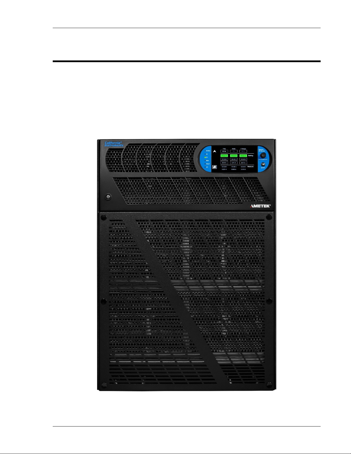
Asterion Series power source models with 1-phase/3-phase output in a 14U chassis. The Asterion Series
is the latest generation of switched-mode power sources that provide precise output having high
accuracy, low distortion, and fast dynamic respons e. With extensive programmability and user interf ace,
it offers a rich feature set and functionality: AC and DC output capability, wide output frequency range,
arbitrary and harmonic waveform generation, sequencing of transient lists, digital power analyzer
measurements, real-time waveform display, and t he capability to be configured in systems comprised of
multi-phase and parallel groups.
Figure 1-1. 14U-Asterion Series Front View
M330511-01, REV-B 13
Page 14

Asterion Series User Manual – 14U Models California Instruments
1.1 General Description
The Asterion Series power sources are available in a 14U chassis at power levels of 12000 VA and
18000 VA. Two AC output voltage ranges are provided, 0-200 VAC/0-400 VAC, with a frequency range of
16 Hz-1200 Hz (with up to 5000 Hz as an option), two DC output ranges, 0-250 VDC/0-500 VDC, and a
combined AC+DC mode. A wide range of AC and DC loads could be powered, including reactive loads
(inductive and capacitive) running at full rated apparent power, and non-linear loads drawing current with
high crest factor, up to 5:1.
TM
iX2
The output has an
output voltage: up to 2X at 50% of full-scale volt age. The Asterion 14U models support two types of AC
inputs, one type being 200-240 VAC, 3-phase, 3-wire plus ground, and the other being
220/380 VAC - 240/415 VAC, 3-phase, 4-wire (with neutral) plus ground. AC input frequency is either
50/60 Hz. The Asterion 14U models provide power factor correction of the AC input with low input current
harmonics, producing PF of 0.95/0.98, 3-wire/4-wire. Two 14U units can be connected in parallel or in
multi-phase groups, with outputs of up to 36 kVA.
Multiple remote digital communications interfaces are available: standard LAN (Ethernet), USB, and
RS-232C, or the optional IEEE-488 (GPIB) interface. The Ast erion Virtual Panels GUI program provides
a convenient graphical user interface, and t he SCPI command set allows access to the full
programmability and functionality. Extensive remote analog and discrete digital control interfaces are
also provided for specialized control application s. The front panel display has capability for control,
programming, and measurements of the power source, and features a men u-based interface with
touch-screen data/command entry.
constant-power characteristic that provides greater output current at reduced
Waveform generation includes standard sine wave and square wave, and extensive programmability to
produce complex waveforms based on harmonics or arbitrary parameter value/time relationships. A
transient generator could combine sequences of voltage, frequency, and wave shape to simul ate
real-world AC or DC disturbances and automate a complex profile of power stimulus to the unit under
test.
The power analyzer utilizes DSP-based digitization of output param eters to implement measurement
functions spanning single parameter values (voltage/current /f requency ), power characteristics
(true/apparent power, crest factor, power factor), and advanced computation using fast Fourier transform
(FFT) derivation of the harmonics and di st ort i on contained in the voltage and current waveforms.
Real-time display of output waveforms is possible thr ough the front panel display or the
Asterion Virtual Panels GUI.
14 M330511-01, REV-B
Page 15
Asterion Series User Manual – 14U Models California Instruments
1.2 Asteri on Series Models
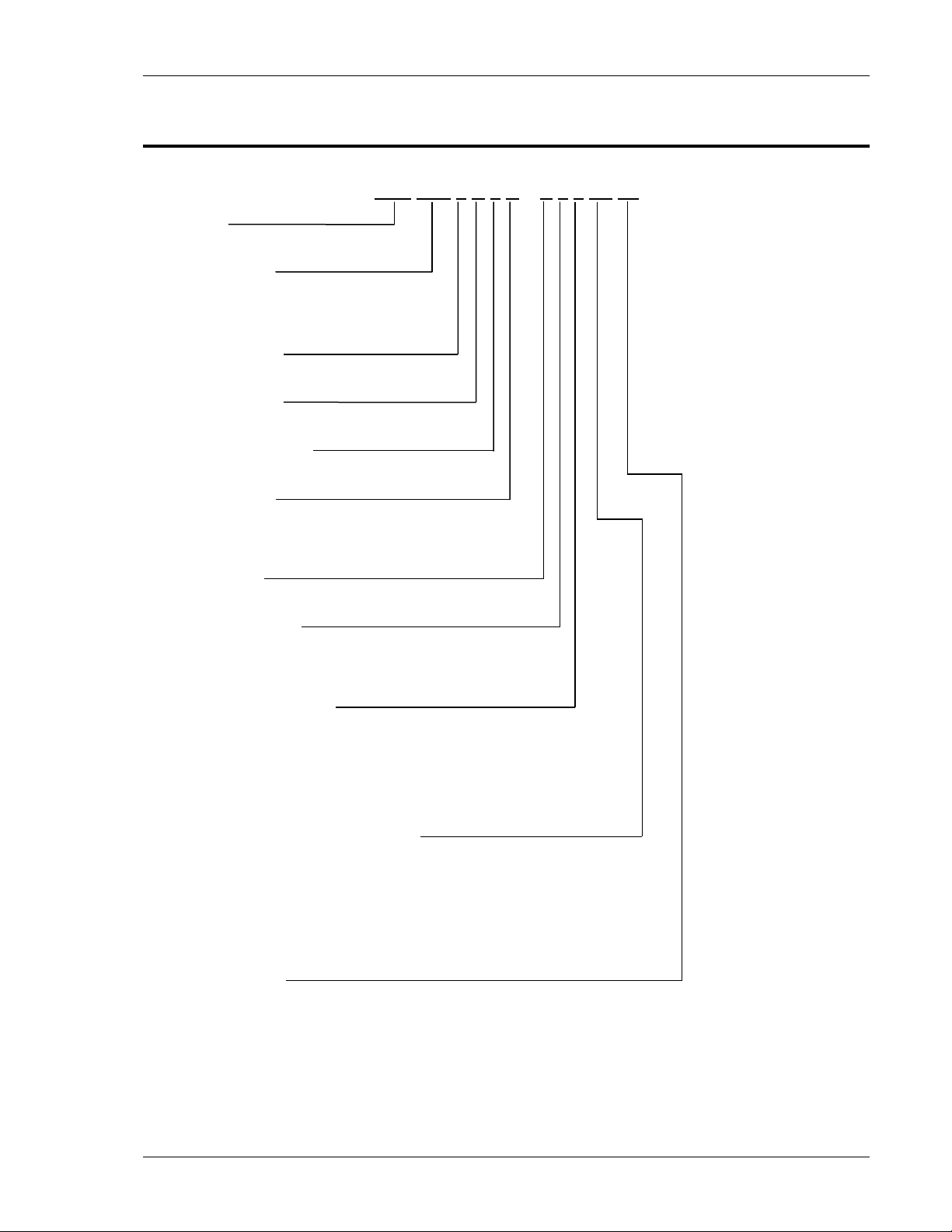
AST 18K 3 A 1 C – E 0 0 0A 00
Series
Asterion
Output Power
12K = 12000 W
18K = 18000 W
Output Phases
3 = 3-Phase
Product Family
A = Standard, C= No Casters
Number of Chassis
1 = 1 Chassis, 2 = 2 Chassis
Input Voltage
C = 200-240 VAC, 3-Phase, 3-Wire + GND
D = 220/380 VAC-240/415 VAC, 3-Phase,
4-Wire (with Neutral) + GND
Front Panel
E = Enhanced
Interface Options
0 = None
1 = GPIB
2 = GPIB - MC
Avionics Test Options
0 = None 6 = B787 – MC C= AVSTD & AMD
1 = B787 7 = AMD – MC D= AVSTD & B787-MC
2 = AMD 8 = B787 - AMD – MC E= AVSTD & AMD -MC
3 = B787 - AMD 9 = AVSTD - MC
4 = AVSTD A = AVALL - MC
5 = AVALL B= AVSTD & B787
Frequency and Clock/Lock Options
0A = None 2B = HF – LKM 3B = HF - FC - LKS
1A = HF 2C = HF - LKS
1B = LF 2D = LF - LKM
1C = FC 2E = LF - LKS
1D = LKM 2F = FC - LKM
1E = LKS 2G = FC - LKS
2A = HF - FC 3A = HF - FC - LKM
Other Options
0A = None 1G = 1399 - MC 2G = 411 - 1399 3C = MB - 411 - 1399
1A = 411 2A = 411 - 413 2H = 413 - 1399 3D = MB - 41 - 1399 - MC
1B = 413 2B = MB - 411 2I = MB - 1399 3E = MB - 413 - 1399
1C = MB 2C = MB - 413 2J = 411 - 1399 - MC 3F = MB - 413 - 1399 – MC
1D = 411 - MC 2D = 411 - 413 - MC 2K = 413 - 1399 - MC 3G = 411 & 413- 1399
1E = 413 - MC 2E = MB - 411 - MC 2L = MB - 1399 - MC 3H = 411 & 413- 1399 - MC
1F = 1399 2F = MB - 413 - MC 3A = MB - 411 - 413 4A = MB - 411 - 413 - 1399
3B = MB - 411 - 413 - MC 4B = MB - 411 - 413 - 1399 - MC
M330511-01, REV-B 15
Page 16

Page 17
Asterion Series User Manual – 14U Models California Instruments
2. Specifications
Unless otherwise noted, the specifications are vali d under the following conditions:
1. Ambient temperature of 25 ± 5°C, after a 30-minute war m -up, and at fixed AC input line and load;
2. Individual unit and individual output phase, with sine wave output, and into a resistive load;
3. For system configurations, specification s are for phase output, line-to-neutral; phase angle
specifications are valid under balanced resistive load conditions.
2.1 Electrical Characteristics
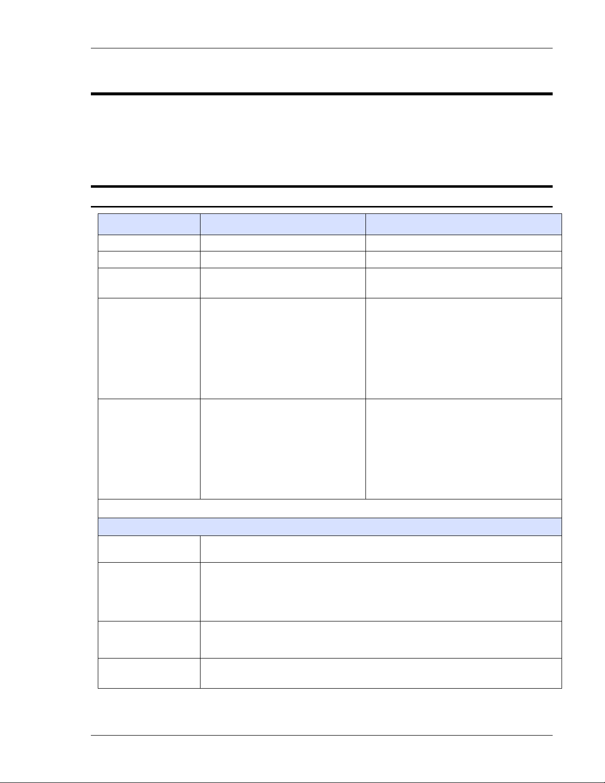
2.1.1 AC/DC Output Specification s
Model AST 12K3 AST 18K3
Enclosure 14U 14U
Output Phase 1-Phase/3-Phase 1-Phase/3-Phase
Output Power
12,000 VA/12000 W;
4000 W, maximum per phase
18,000 VA/ 18,000 W;
6,000 W, maximum per phase
Low-Range:
20 A(RMS) at 200 VAC;
AC and AC+DC
Output Current,
Full-Scale,
per Phase
DC Output Current,
Full-Scale,
per Phase
1
Refer to “iX2TM Constant-Power Mode Output Charact eristic” on Section 2.1.2.
1
40 A
(RMS) at 100 VAC
High-Range:
10 A(RMS) at 400 VAC;
(1)
(RMS) at 200 VAC
20 A
1-Phase output mode: rating times 3.
Low-Range:
16 ADC at 250 VDC;
1
32 ADC
High-Range:
8 ADC at 500 VDC;
16 ADC
1-Phase output mode: rating times 3.
at 125 VDC
1
at 250 VDC
All Models
Output Current,
Maximum RMS
iX2TM
Constant-Power
Mode
AC and AC+DC
Output Voltage,
Full-Scale
DC Output Voltage,
Full-Scale
200% of the full-scale RMS current at ≤50% of full-scale vol tage. Refer to Figure 2-1 for
current rating as a function of output voltage and frequency.
Constant-Power output capabilit y in each output voltage range with ful l rated output
power from 50% of full-scale output voltage to 100% of full-scale; the output current
increases to 200% of rated current at 50% full-scale output voltage from 100% rated
current at 100% of full-scale voltage. Refer to Figure 2-1 for current rating as a function
of output frequency.
Low-Range: 0 to 200 V(RMS); High-Range: 0 to 400 V(RMS)
HF Option: derate full-scale output voltage from 4 kHz to 5 kHz, as follows.
Low-Range: 0 to 250 VDC; High-Range: 0 to 500 VDC
Low-Range:
30 A (RMS) at 200 VAC;
1
60 A
(RMS) at 100 VAC
High-Range:
15 A (RMS) at 400 VAC;
1
(RMS) at 200 VAC
30 A
1-Phase output mode: rating times 3.
Low-Range:
24 ADC at 250 VDC;
48 ADC
High-Range:
12 ADC at 500 VDC;
24 ADC
1-Phase output mode: rating times 3.
1
at 125 VDC
1
at 250 VDC
M330511-01, REV-B 17
Page 18

Asterion Series User Manual – 14U Models California Instruments
√
1.5
DC Offset Voltage,
Typical
Output Float Voltage 566 V(PK), maxim um from either output terminal to chass is
Voltage Accuracy
Voltage Resolution ≤0.02 V, AC, DC, and AC+DC mode
Voltage Temperature
Coefficient, Typical
Voltage Stability,
Typical
Voltage Distortion
Voltage Slew Rate,
Typical
Current
Programming Range
Current
Programming
Accuracy
Line Regulation ±0.015% of full-scale voltage, for a ±10% input line change; DC, or 40 Hz to 5 kHz.
Load Regulation
V/I Programming
Overrange, Typical
Noise Level, Typical
Remote Sense 5 V(RMS), maximum total output lead drop
Crest Factor
Power Factor 0, lagging to 0, leading
Frequency Range
Frequency Accuracy
Frequency
Resolution
±20 mVDC, ≥40 Hz
± (0.1% of actual + 0.2% of full-scale) for D C, and AC 16 Hz to 1.2 kHz, add ±0.1% of full
scale for AC+DC mode; >1.2 kHz, add ±0.2% of full-scale/kHz; Valid from 5% of
full-scale to 200 VAC(RMS)/250 VDC in low-range and 400 VAC(RMS)/500 VDC in
high-range; with sense leads connected.
≤100 ppm/°C of full-scale
±0.1% of full-scale over 8 hours; with constant line, load, and temperature;
with sense leads connected
0.25% maximum, 16 Hz to 100 Hz; 0.5% maximum, >100Hz to 500 Hz; and
1% maximum, >500 Hz to 1.2 kHz, plus 0.5%/kHz to 5 kHz; at full linear load or no l oad;
valid for output voltage >5% of full -scale at full load, and >15% of full-scale at no load.
≥10 V/µs with full-scale programmed vol tage step
Programmable from zero to 200% of full-scale rating in each output range. Refer to
Figure 2-1 for current rating as a func tion of output voltage and frequency.
±(0.3% of actual + 0.5% of full-scale) for D C, and AC 16 Hz to 1.2 kHz; add ±0.1% of
full-scale for AC+DC mode. Valid from 5% of full-scale to 100% of full-scale.
HF option: for High-Range, add 1.2% of maximum/kHz; for Low-Range, add 0. 1% of
maximum/kHz. Valid from 20% of full-scale to 200% of full-scale.
For multi-chassis configurations, multiply the accuracy by
chassis.
±0.025% of full-scale voltage, for 100% of rated resistive load change; DC, or 40 Hz to
1.2 kHz, above 1.2 kHz, add ±0.015% of full-scale/kHz
1% of full-scale
AC output: 450 mV(RMS), low-range; 750 mV(RMS), high-range;
at ≥40 Hz output frequency; bandwidth, 20 kHz to 1 MHz;
DC output: 400 mV(RMS), low-range; 700 mV(RMS), high-range;
bandwidth, 20 Hz to 1 MHz.
AST12K3, AST18K3: 5:1 of full-scale current in each output range (rati o of peak output
current to RMS full-scale output c urrent).
Standard models: DC, and 16 Hz to 1.2 kHz;
LF option: DC, and 16 Hz to 550 Hz;
HF option: DC, and 16 Hz to 5 kHz.
Standard models: ±(0.01% of actual + frequency resolution/2)
FC option: ±0.25%
0.01 Hz resolution, 16-81.91 Hz;
0.1 Hz resolution, 82-819.1 Hz;
1 Hz resolution, 820-5000 Hz;
with LKM/LKS option: 1 Hz resolution, 16-50 00 H z .
, where is number of
18 M330511-01, REV-B
Page 19
Asterion Series User Manual – 14U Models California Instruments
Frequency
Temperature
Coefficient, Typical
Phase Programming
Range
Phase Accuracy ±1º, 16 Hz to 100 Hz; ±2º >100 Hz to 1.2 kHz, plus ±1º/kHz above 1.2 kHz
Phase Programming
Resolution
10 ppm/ºC of full-scale in each range
0.0 º to 360.0 º, relative to external synchronization signal; in multi-phase group, Auxiliary
unit output voltage is relative t o the Master unit output voltage, with the Master unit as
reference 0°.
±0.4º
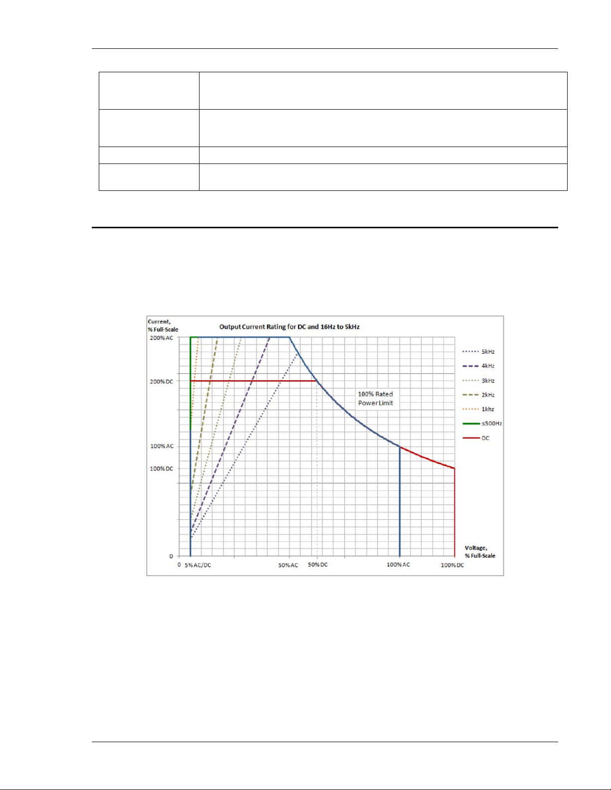
2.1.2 iX2
TM
Constant-Power Mode Output Characteristic
The iX2TM Constant-Power mode has an output characteristic where full rated output power is available
from 50% of full-scale output voltage to 100% of full-scale output voltage, as depicted in the graph of Figure
2-1. The output current versus output voltage follows a constant-power relation where the output current
would be 200% of the full-scale value when t he output volt age is 50% of full-scale. The current ratings are
also a function of output frequency, as shown i n Figure 2-1 above 500 Hz for the AST12K3 and AST18K3
units.
TM
Figure 2-1. iX2
Constant-Power: Output Current Versus Voltage, AST 12K3 and
AST18K3
M330511-01, REV-B 19
Page 20

Asterion Series User Manual – 14U Models California Instruments
Input Voltage type
180-264 VAC, 3-Phase,
Neutral) + GND Input
Input
Neutral) + GND Input
Nominal Rating
Input Frequency Range
Efficiency1, Typical
Hold-Up Time3, Typical
2.1.3 AC Input Specifications
Model AST 12K3 AST 18K3
Enclosure 14U 14U
(Only Factory
Configurable)
Input Voltage,
Nominal Rating for
3-phase, 3-Wire + GND
Input
Input Voltage,
Operating Range for
3-phase, 3-Wire + GND
Input
Input Voltage,
Nominal Rating for
3-Phase, 4-Wire (with
Neutral) + GND Input
Input Voltage,
Operating Range for
3-phase, 4-Wire (with
Input Current,
Maximum with
3-Phase, 3-Wire + GND
3-Phase, 3-Wire + GND, or
3-Phase, 4-Wire (with Neutral) + GND
200-240 VAC, 3-Phase, Line-Line 200-240 VAC, 3-Phase, Line-Line
180-264 VAC, 3-Phase,
3-Wire, Line-Line
220/380 VAC-240/415 VAC, 3-Phase,
4-Wire, Neutral required
197/342 VAC-264/457 VAC, 3-Phase,
4-Wire, Neutral required
56 A(RMS) at 180 VAC
3-Phase, 3-Wire + GND, or
3-Phase, 4-Wire (with Neutral) + GND
3-Wire, Line-Line
220/380 VAC-240/415 VAC, 3-Phase,
4-Wire, Neutral required
197/342 VAC-264/457 VAC, 3-Phase,
4-Wire, Neutral required
64 A(RMS) at 180 VAC
Input Current,
Maximum with
3-Phase, 4-Wire (with
Input Frequency,
Inrush Current, Typical
Power Factor2, Typical
Isolation Voltage 2200 VAC, input to output; 1350 VAC, input to chassis
1
a) At full load and DC or 16 Hz to 1.2 kHz output frequency, with AC input voltage of 208 V(RMS) and 50/60 Hz
input frequency for 3-Phase, 3-Wire + Ground models;
b) At full load and DC or 16 Hz to 1.2 kHz output frequency, with AC input volt age of 400 V(RMS) and 50/60 Hz
input frequency for 3-Phase, 4-Wire (with Neutral) + Ground models.
28 A(RMS) at 197/342 VAC
50 Hz, 60 Hz
47-63 Hz
a) 55 A(PK) at 264 VAC, line-line for 3-phase, 3-wire + GND input
b) 55 A(PK) at 264/457 VAC line-line for 3-phase, 4-wire (with neutral) + GND input
76%
4-Wire Input: 0.98; active PFC
3-Wire Input: 0.95; active PFC
≥10 ms ≥10 ms
42 A(RMS) at 197/342 VAC
4-Wire Input: 0.98; active PFC
3-Wire Input: 0.95; active PFC
20 M330511-01, REV-B
Page 21

Asterion Series User Manual – 14U Models California Instruments
2
a) At full load and with AC input voltag e of 208 V(RMS) and 50/60 Hz input frequency for 3-Phase, 3-Wire +
Ground models;
b) At full load and with AC input voltag e of 208 V(RMS) and 50/60 Hz input frequency for 3-Phase, 4-Wire (with
Neutral), 4-Wire + Ground models.
3
a) At full load and with AC input voltage of 208 V(RMS) and 50/60 Hz input frequenc y f or 3-Phase, 3-Wire +
Ground models;
b) At full load and with AC input voltag e of 208 V(RMS) and 50/60 Hz input frequency for 3-Phase, 4-Wire (with
Neutral) + Ground models.
M330511-01, REV-B 21
Page 22

Asterion Series User Manual – 14U Models California Instruments
2.1.4 AC Output Measurements
Parameter Specification
Voltage Range, Full-Scale AC and AC+DC output: 0-500 V(RMS)
±(0.1% of actual + 0.2% of full-scale) for A C 16 Hz to 1.2 kHz; >1.2
Voltage Accuracy
Voltage Resolution 20 mV
Current Range,
Maximum
Current Accuracy
Current Resolution 2 mA; 1-Phase output mode in 3-Phase models: 6 mA.
Peak Current Range,
Full-Scale
Peak Current Accuracy
Peak Current Resolution 5 mA; 1-Phase output mode in 3-Phase models: 15 mA.
Frequency Range 16 Hz to 5.0 kHz
Frequency Accuracy ±(0.01% of actual + frequency resolution/2)
Frequency Resolution 0.01 Hz: 16-81.91 Hz; 0.1 Hz: 82.0-819.1 H z; 1 Hz: 820-5.0 kHz
Phase Range 0-360°
Phase Accuracy ±1°, 16 Hz to 100 Hz; ±2°, >100 Hz to 1.2 kHz; ±5°, >1.2 kHz
Phase Resolution 0.1°, 16-100 Hz; 1°, >100 Hz to 5 kHz
Real Power Range, Full-Scale Output power rating of model.
Real Power Accuracy
Real Power Resolution 1 W
Apparent Power Output power rating of model.
Apparent Power Accuracy
Apparent Power Resolution 1 VA
Power Factor Range 0-1
Power Factor Accuracy ±2% of full-scale
kHz, add ±0.2% of full-scale/kHz; add ±0.1% of full-scale for AC+DC
mode. Valid from 5% of full-scale to 200 V AC(RMS) in low-range and
400 VAC(RMS) in high-range; with sense l eads connected.
AST 12K3: ± 0-45 A(RMS) per phase;
AST 18K3: ± 0-67.5 A(RMS) per phase;
1-Phase output mode in 3-Phase models: r ating times 3
±(0.3% of actual + 0.5% of maximum) for A C 16 Hz to 1.2 kHz; add
±0.3% of maximum/kHz; add ±0.1% of maximum for AC+DC mode.
Valid from 5% of full-scale to 100% of f ull-scale.
AST 12K3: ± 0-225 A(PK) per phase;
AST 18K3: ± 0-337.5 A(PK) per phase;
1-Phase output mode in 3-Phase models: r ating times 3.
±(0.5% of actual + 0.7% of maximum) for A C 16 Hz to 1.2 kHz; add
±0.1% of maximum for AC+DC mode. Valid from 5% of full-scale to
100% of full-scale.
HF Option: for High-Range, add 1% of maximum/kHz; for
Low-Range, add 0.1% of maximum/kHz. Valid from 20% of full-scale
to 200% of full-scale.
±(0.4% of actual + 0.7% of full-scale) for AC 16 Hz to 1.2 kHz;
>1.2 kHz, add ±0.4% of full-scale/kHz; add ±0.2% of full-scale for
AC+DC mode.
±(0.4% of actual + 0.7% of full-scale) for AC 16 Hz to 1.2 kHz; >1.2
kHz, add ±0.4% of full-scale/kHz; add ±0. 2% of full-scale for AC+DC
mode.
1
22 M330511-01, REV-B
Page 23
Asterion Series User Manual – 14U Models California Instruments
√
1.5
√
1.5
Parameter Specification
1
Power Factor Resolution 0.01
1
Accuracy specifications apply a bove 100 counts of resolution; for multi-chassis configurations, multiply the
output current and power by the num ber of chassis, and their accuracy specifications by
, where is
number of chassis; power factor accuracy applies for PF > 0.5 and output apparent power > 50% of m aximum
rating; frequency measurement s pecifications valid for output voltage >5% of full-scale.
2.1.5 DC Output Measurements
Parameter Specification
Voltage Range, Full-Scale ±500 VDC
±(0.1% of actual + 0.2% of full-scale); valid i n l ow-range from 5% of
Voltage Accuracy
full-scale to 250 VDC, and in high-range from 5% of full-scale to
500 VDC; with sense leads connected.
Voltage Resolution 25 mV
AST 12K3: ± 0-45 A(RMS) per phase;
Current Range, Maximum
AST 18K3: ± 0-67.5 A(RMS) per phase;
1-Phase output mode in 3-Phase models: rating times 3.
Current Accuracy
±(0.5% of actual + 0.5% of full-scale); valid fr om 5% of full-scale to
100% of full-scale.
Current Resolution 2 mA; 1-Phase output mode in 3-Phase models: 6 mA.
Peak Current Range,
Full-Scale
Peak Current Accuracy
AST 12K3: ± 0-225 A(PK) per phase;
AST 18K3: ± 0-337.5 A(PK) per phase;
1-Phase output mode in 3-Phase models: rating times 3.
±(0.5% of actual + 0.7% of maximum); valid from 5% of full-scal e to
100% of full-scale.
Peak Current Resolution 5 mA; 1-Phase output mode in 3-Phase models: 15 mA.
Power Range, Full-Scale Output power rating of model.
Power Accuracy ±(0.4% of actual + 0.7% of full-scale)
Power Resolution 1 W
1
Accuracy specifications apply a bove 100 counts of resolution; for multi-chassis configurations, mult i ply the
output current and power by the num ber of chassis, and their accurac y specifications by
number of chassis.
1
, where is
M330511-01, REV-B 23
Page 24
Asterion Series User Manual – 14U Models California Instruments
√
1.5
2.1.6 Harmonics Measurements
Parameter Specification1
Frequency, Fundamental 16-81.91 Hz, 82.0-819.1 Hz, 820-960 Hz
Fundamental Frequency Resolution 0.01 Hz: 16-81.91 Hz; 0.1 Hz: 82.0-819.1 Hz; 1 Hz: 820-960 Hz
Harmonic Frequency 32 Hz to 48 kHz; 2nd to 50th harmonic
Fundamental Voltage Accuracy ±(0.2% of actual + 0.3% of full-scale) for 16 Hz to 960 Hz.
Fundamental Voltage Resolution 20 mV
Harmonic Voltage Accuracy ±(0.2% of actual + 0.3% of full-scale + 0.3% of full-scale/kHz).
Harmonic Voltage Resolution 20 mV
Fundamental Current Accuracy ±(0.4% of actual + 0.6% of full-scale).
Fundamental Current Resolution 2 mA; 1-Phase output mode in 3-Phase models: 6 mA.
Harmonic Current Accuracy ±(0.4% of actual + 0.6% of full-scale + 0.4% of maximum/kHz).
Harmonic Current Resolution 2 mA; 1-Phase output mode in 3-Phase models: 6 mA.
1
Accuracy specifications apply a bove 100 counts of resolution; for mul ti-chassis configurations, multiply the
current accuracy by
of full-scale to 100% of full-scale.
, where is number of chassis. Voltage and current measurements ar e v al id from 5%
2.1.7 Protection Function Characteristics
Function Characteristic
Output Overvoltage Protection (OVP)
Output Current Limit Protection
Output Short-Circuit Protection Instantaneous and RMS current-limit
AC Input Overcurrent Protection Internal fuses in each phase for fault is olation; not user replaceable
AC Input Undervoltage Protection Automatic shutdown for insufficient AC input voltage
AC Input Transient Protection Protection to withstand EN61326-1, Class-A surge levels
Overtemperature Protection (OTP)
Programmable to 115% of full-scale output voltage;
exceeding OVP threshold results in shutdown of output.
User-selectable constant-current mode or current-limit mode, with
programmable current setpoint;
in constant-current mode, output current is regulated to setpoint;
in current-limit mode, exceeding c ur rent-limit setpoint results in
shutdown of output;
current limit delay: programmable from 100 ms to 10s.
Internal temperature monitors cause shutdown of output if
temperature thresholds are exceeded
24 M330511-01, REV-B
Page 25
Asterion Series User Manual – 14U Models California Instruments
2.2 Regulator y Agency Compliance
Parameter Specification
EMC
Safety
CE Mark LVD Categories
RoHS
CE marked for EMC Directive 89/336/EEC per EN61326-1:2013, Class-A for
emissions and immunity as required f or the EU CE Mark.
CE marked for LVD compliance 2006/95/EC to EN 61010-1 Third Edition as
required for the EU CE mark.
Installation Overvoltage Category: ΙΙ; Pollution Degree: 2; Class II equipment;
indoor use only.
CE marked for compliance with EU Directive 2011/65/EU for Restriction of
Hazardous Substances in Electric al and Electronic Equipment.
2.3 Environm ent al Specifications
Parameter Specification
Operating Temperature 0°C to 40°C (32° F to 104° F)
Storage Temperature -40°C to 85°C ( -40°F to 185° F)
Altitude 2000 m (6,562 ft)
Relative Humidity 5-95 %, non-condensing
Vibration MIL-PRF-28800F, Class 3; 5-500 H z per Paragraph 4.5.5.3.1.
Shock
MIL-PRF-28800F, Class 3; 15G half-sine with 11ms duration per
Paragraph 4.5.5.4.1.
Transportation Integrity ISTA Test Procedure 1A
M330511-01, REV-B 25
Page 26
Asterion Series User Manual – 14U Models California Instruments
2.4 Mechanical Specifications
Parameter Specification
Dimensions
Unit Weight
Shipping Weight
Chassis Material Steel with plastic front panel
Chassis Finish Black power-coat chassis with galvanized-zinc (G90) panels
Installation
Cooling
Acoustic Noise
Rackmount: H, 24.5” (622 mm); W , 17.44” (443 mm); D, 29.6” (752 mm)
Standalone (with casters): H, 28.5” (724 mm); W, 17.44” (443 mm); D, 29.6” (752 mm)
AST 12K3: 305 lb / 138.3 kg;
AST 18K3: 401 lb / 181.9 kg.
AST 12K3: 460 lb / 208.7 kg;
AST 18K3: 556 lb / 252.2 kg.
Protective covers are provided for A C input, AC/DC output, and output sens e;
rackmount: per ANSI-EIA-310-D; optional front panel mounting flanges and chassis
L-brackets.
Force-air cooling; linear, variable fan speed control; air intake at front and exhaust at
rear.
68 dBA, maximum; m easured at 1 m with A-weighting.
2.5 Remote Cont r ol Digital Interface Characteristics
Interface Characteristic
LAN
Ethernet 10BASE-T and 100BASE-T over twisted-pair cables compliant with IEEE 802.3;
Connector: 8P8C modular jack.
USB
RS-232C
IEEE-488 (Option)
Firmware Upgrade
Serial interface compliant to USB 2. 0;
Connector: Type-B receptacle.
Serial interface compliant to RS-232C;
Protocol: data bits, 7 with parit y and 8 without parity; stop bits, 2; baud rate, 9600 to
115200; handshake, CTS and RTS;
Connector: Subminiature-D, 9-contact receptacle.
Parallel interface complies with IEEE-488.1, IEEE-488.2, and the SCPI command
specification;
command execution response tim e, 10 ms, typical;
connector: IEEE-488.1 compliant.
Firmware could be upgraded throug h the LAN, USB, or RS-232 interfaces. Upgrade
through IEEE-488 is not supported.
26 M330511-01, REV-B
Page 27

Asterion Series User Manual – 14U Models California Instruments
2.6 Remote Cont r ol Anal og/Digital Signal Characteristics
Function Characteristics
Signal input for output voltage waveform programming by external analog reference;
External Analog
Programming of
Output Voltage
Waveform
External Analog
Programming of
Output Voltage
Amplitude
External Analog
Modulation of
Output Voltage
AC or DC input signal: 0V to user-selectable maximum range value within ±2.5 V (PK) to
±10 V(PK), corresponding to maximum range of 1.77 V(RMS) to 7.07 V(RMS), for zero to
full-scale RMS output voltage; with AC waveform, from 16 Hz to 5 kHz (option dependent);
programming accuracy, ±2% of f ull -scale output;
input impedance, 40 kΩ, typical.
Signal input for output voltage amplitude programming; waveform i s set by internal
controller reference;
DC input signal: 0V to user-selectable maximum range value within 2.5 VDC to10 VDC, for
zero to full-scale RMS of internally program m ed output voltage waveform;
programming accuracy, ±2% of ful l-scale output;
input impedance, 40 kΩ, typical.
Signal input for output voltage m odulation; waveform is set by internal controller reference;
AC or DC input signal with 0V to ±7.07 V(PK), 0-5 V(RMS) for 0-20% of full-scale out put
voltage amplitude modulation;
programming accuracy, ±2% of ful l-scale output;
input impedance, 40 kΩ, typical.
Trigger Output
Output Voltage
Monitor Outputs
Trigger Input
Synchronization
Signal (SYNC)
Input
Remote Inhibit
Input
Summary Fault
Switch Output
Signal output with dual function: user-selectable as either function trigger or list trigger;
function trigger provides a pul se for any programmable change in output voltage or
frequency; list trigger provides a pulse if programmed as part of li s t transients;
logic level, active-low pulse with duration of 550 µs, typical.
Signal outputs for each output phase for monitoring the waveforms of the command signals
of the output amplifiers;
0-5 V(RMS), typical
, signal range for zero to full-scale output voltage.
Signal input for external trigge r for execution of programmed values or transient lists;
logic level, TTL-compatible.
Signal input for external square wave to control the output frequency a nd phase, with
waveform generated by the internal reference;
logic level, TTL-compatible.
Signal input to turn the output off/on; logic level, TTL-compatible; user-selectable as
active-high or active-low.
Switch output indicating that a Summary Fault (DFI) condition is present;
normally-closed, bidirectional AC/DC solid-state switch;
closed-circuit for fault or when unit is turned off (open-circuit for no fault present);
switch ratings: ±12V, maximum peak voltage; 0.1A, maximum current; 2.5Ω, maximum
closed resistance; 6µA, maximum open-circuit leakage current at 12V.
Signal outputs for Master Clock and Lock signals used in synchronizing two or more power
LKM (Option)
LKS (Option)
sources;
logic level, TTL-compatible.
Signal inputs for Auxiliary Clock and Lock signals used in synchronizing two or more power
sources;
logic level, TTL-compatible.
M330511-01, REV-B 27
Page 28

Asterion Series User Manual – 14U Models California Instruments
2.7 Operational Characteristics
Parameter Characteristic
Multi-chassis configurations c ould be formed by paralleling unit s in 1-Phase
or multi-phase groups using one Master unit and one auxiliary unit.
Parallel Operation
Output Relays
Automatic 1-Phase/3-Phase
Outputs
Non-Volatile Memory 16 complete instrum ent setups and transient lists, 100 events per list.
Transient Generator
Calibration
Fault Identification On-board diagnostics identify when an assembly has experienced a fault.
XLOAD Output Characteristic
Automatic Level Control (ALC)
LF, option Low frequency option: output frequency range of 16 Hz to 550 Hz.
HF, option High frequency option: output frequency range of 16 Hz to 5 kHz.
FC, option
LKM, option
LKS, option Clock and Lock interface option, Auxiliary unit.
MB, option Upgrades all chassis to Enhanced models in a multi-chassis configuration.
Maximum power that can be obtaine d by paralleling is limited to 36 kW.
Setup of the multi-chassis configuration is automatically accomplishe d when
the chassis are interconnected with the interface cables, and require no user
setup, except to wire the outputs.
Isolation and range relays are provided internally to automatically configure
the outputs, turn the output on/off, and disconnect the load from the outp ut
amplifier when in the off state.
User-selectable 1-Phase or 3-Phase outputs with automatic configuration of
all phases.
In 1-Phase mode, user must connect together the output phases A, B, C
and the three return terminals in order to draw full power from the unit. To
interface the relay to connect the phases out side the unit, a relay control
signal output for 1-Phase operation is provided in 14U Models. Ref er to
Section 3.7.2 and Section 3.12.4 for more details.
Output could be controlled to prod uc e transient events with 500 µs
programming resolution:
Voltage: drop, step, sag, surge, sweep;
Frequency: step, sag, surge, sweep;
Voltage and Frequency: step, sweep.
Calibration interval is 1 year; calibration is firmware-based through the digital
interface or Virtual Panels GUI.
User-selectable XLOAD mode provides revised regulation characteristics for
additional stability margins when driving large capacitive loads.
User-selectable ALC operation enables a digitally implement ed feedback
control loop to provide precise regulation of the RMS value of the output
voltage.
Reduced frequency control opti on: ±0.25% accuracy of output frequency;
deletes external waveform program m ing signal.
Clock and Lock interface option, Mast er uni t.
28 M330511-01, REV-B
Page 29

Asterion Series User Manual – 14U Models California Instruments
2.8 Front Panel Cont r ols/ I ndicators
Model Type Controls/Indicators
Touch-Panel, TFT color LCD displa y with menu-based control;
rotary encoder for menu navigation and parameter adjustment and entry, with
integrated selection switch.
POWER switch: turns unit on/off.
OUTPUT switch: turns output of the unit on/off.
OUTPUT LED: integrated into the OUTPUT switch; indicates that the output of the unit
has been turned on.
Enhanced
CC LED: indicates that the unit is in constant-current mode and the output current is
being regulated.
CV LED; indicates that the unit is in c onstant-voltage mode and the output v ol tage is
being regulated.
HI RNG LED: indicates that the high-voltage output range has been selected;
FAULT LED: indicates that an internal faul t has been detected and the output has been
shut down.
REM LED: indicates that the unit is un der control of the remote digital interface.
LXI LED: LXI status annunciation.
ATE
No front-panel display; only status indicators.
POWER switch: turns unit on/off.
UPDATE switch: enables bootloader f or firmware upgrade.
POWER LED: indicates that the POWER switch has turned the unit on.
OUTPUT LED: indicates that the outp ut of the unit has been turned on.
CC LED: indicates that the unit is in constant-current mode and the output current is
being regulated.
CV LED; indicates that the unit is i n c onstant-voltage mode and the output voltage is
being regulated.
HI RNG LED: indicates that the high-voltage output range has been select ed.
FAULT LED: indicates that an internal faul t has been detected and the output has been
shut down.
REM/LAN LED: indicates that the unit is under c ontrol of the remote digital interface,
and LXI status annunciation.
M330511-01, REV-B 29
Page 30

Asterion Series User Manual – 14U Models California Instruments
Phase-A/B/C (Line) and RTN (Return);
2.9 Rear Panel Connectors
Connector Description
3-Phase, 3-Wire AC input: L1, L2, and L3;
AC Input
Safety-Ground M5-0.8 x 15 chassis stud
3-Phase, 4-Wire AC input: L1, L2, L3 and NEU;
connector: X4 feedthrough terminals; Phoenix P/N HDFKV 50/7085 22.
AC/DC Output
AC/DC Output
Remote Sense
Functional-Ground M5-0.8 x 15 mm chassis stud
External Interface
External
Input/output Control
External Relay
Interface
Auxiliary Interface
Master Interface
Clock and Lock
(LKM and LKS
options)
Command Monitor
Outputs
Trigger Output
LAN Interface
RS-232C Interface
USB Interface
IEEE-488 Interface
(Option)
connector: X6 feedthrough terminals; Phoenix P/N HDFKV 50/708522.
Phase-A/B/C (Line) and RTN (Return);
connector: X4 feedthrough terminal terminals; Phoenix P/N: 070 6605.
Control signal interface to external chassis; connector: high-dens i ty, 15-contact, female
Subminiature-D.
Control analog/digital signal interface for user remote control;
safety isolation SELV-rated; connector: high-density, 15-contact, female
Subminiature-D.
Relay contact interface (isolated) indicating 1-Phase output m ode of operation;
connector: Molex P/N 43045-0613. Refer to Section 3.12.4
Control signal interface on Auxil iary unit coming from Master unit for multi-chassis
operation; connector, high-density, 26-contact, female Subminiature-D.
Control signal interface on Master unit going to Auxiliary unit for multi-chassis
operation; connector: high-density, 26-contact, female Subminiature-D.
Signal control interfaces for sync hr onization of multiple units;
signal outputs on Master unit, and signal inputs on Auxiliary units;
safety isolation SELV-rated; connectors: individual BNC.
Signal outputs of each output phase for monitoring waveforms of command signals to
internal output amplifiers;
safety isolation SELV-rated; connector: individual BNC.
Signal output with dual function, eit her function trigger or list trigger ;
safety isolation SELV-rated; connector: BNC.
Ethernet 10BASE-T and 100BASE-T;
safety isolation SELV-rated, referenced to chassis; connector: 8P8C modular jack.
Serial interface to RS-232C;
safety isolation SELV-rated, referenced to chassis; connector: Subminiature-D,
9-contact receptacle.
Serial interface to USB 2.0;
safety isolation SELV-rated, referenced to chassis; connector: Type-B.
Parallel interface to IEEE-488.1, IEEE-488.2;
safety isolation SELV-rated, referenced to chassis; connector: IEEE-488.1 compliant.
30 M330511-01, REV-B
Page 31

Asterion Series User Manual – 14U Models California Instruments
2.10 Firmware/Software Options
Option1
B787, (MC) Avionics Electrical Power Quality Test Software; Boeing 787B3-0147 A/B/C (B787).
AMD, (MC) Avionics Electrical Power Quality Test Software; Airbus AMD24 C (A400M).
B787 & AMD, (MC) Includes both B787 and AMD options.
Avionics Electrical Power Quality Test Software Package;
AVSTD, (MC)
AVALL, (MC)
1399, (MC) MIL-STD-1399-300B shipboard power test software
411, (MC) IEC 61000-4-11 voltage dips and interruptions EMC test software.
413, (MC) IEC 61000-4-13 harmonics and I nter-harmonics EMC test hardware and software.
411 & 413, (MC) Includes both 411 and 413 options.
MIL1399, (MC) Interface Standard for Shipboard Systems Electric Power, Alternating Curr ent
MC Options are installed in all chassis of a multi-chassis (MC) configuration.
1
For Avionics options, reference the Avionics Software Manual (P/N 4994-971) for test details. All options require
the use of Asterion Virtual Panels, graphical user interface Windo ws appli cat ion software (refer to AMETEK PPD
website, www.powerandtest.com
includes 160 (RTCA/DO160 E/F/G), 704 (MIL-STD 704 A/B/C/D/E/F),
ABD (Airbus ADB100.1.8 D/E), A 350 (Airbus ADB100.1.8.1 B/C).
Avionics Electrical Power Quality Test Software Package;
includes AVSTD, B787, AMD.
, to download latest version).
Description
M330511-01, REV-B 31
Page 32

Page 33

Asterion Series User Manual – 14U Models California Instruments
3. Installation
3.1 Unpacking
Inspect the shipping carton for possible damage before unpacking the unit. Carefully unpack the
equipment. Save all packing materials until inspe ct i on is complete. Verify that all items listed on the
packing lists have been received. Visually inspect all ex terior surfa ce s for dented or dam aged exterior
surfaces, and broken connectors, display, or controls. External damage might be an indication of
internal damage.
If any damage is evident, immediately contact the carrier that delivered the unit and submit a damage
report. Failure to do so could invalidate future clai m s. Direct repair issues to AMETEK Customer Service
Department at 858-458-0223 (local) or 1-800-733-5427 (toll free in North Ame rica).
3.1.1 Contents of Shipment
Depending on the model, configuration, and options selected for your Asterion Series power source, the
ship kit may include additional parts and accessorie s.
Minimum items included in the ship kit (P/N 5330561-01R):
1. AMETEK CD-ROM (P/N CIC496) containing the Asterion Series User Manual
(P/N M330511-01), and the Asterion Series Programming Manual (P/N M330100-01);
2. External relay interface mating connector (AMETEK P/N, 856-429-06, M anufacturer Molex
P/N, 43025-0600) and crimp pin, quantity six (AMETEK P/N, 856-030-01, Manufacturer Molex
P/N, 43030-0001)
Note: If any of these parts are missing, contact AMETEK Customer Service Department at
858-458-0223 (local) or 1-800-733-5427 (toll free).
Optional accessories:
5330561-02R: Rackmount kit
890-010-26: Auxiliary cable, 60” long; one cable is r equired per unit that is placed in parallel; two
units can be paralleled.
250562: LKM/LKS options (Clock/Lock) interface cables, 36” long; two cables are require d for
every pair of units in a multi-phase group;
250561: LKM/LKS options (Clock/Lock) interface BNC T-adapter; two adapters are requi red for
every pair of units in a multi-phase group;
M330511-01, REV-B 33
Page 34

Asterion Series User Manual – 14U Models California Instruments
3.2 Mechani cal Installation
The Asterion Series power source is designed for both standalone and rackmount applications. The
standalone models have enclosures with casters for floor standing mobility.
The unit is forced-air cooled with internal fans drawing air in from the front and exhausting at the rear.
The front and rear of the unit must be kept clear of obstruction and clearance must be maintained to
allow unimpeded airflow. Special consideration must be made to overall air flow characteristics and the
resultant internal heat rise when a source is installed inside enclosed cabinets to avoid excessive heating
and over-temperature problems. The temperat ure of the ambient air at the air intake should not exceed
40°C.
WARNING!
This unit is intended for installation in a protected env i ronment. Exposure to conductive
contaminants or corrosive compounds/gases t hat could be ingested into the chassis
could result in internal damage. Install the powe r source in a temperature and humidity
controlled indoor area.
CAUTION!
The power source should be provided with proper ventilation. The front and rear of the
unit must be free of obstructions. To ensure proper airflow, a minimum 2" clearance from
the rear air outlet is required.
CAUTION!
No user serviceable parts are inside; service is only to be performed by qualified
personnel.
3.2.1 Handling
The Asterion power source is equipped with three M8-1.25 clinch nut s on the both sides of chassis. Use
these clinch nuts to mount eyelet rings/eye bolts or shipping straps (supplied with unit) as shown in the
Figure 3-1. Using the eyelet rings or shipping straps, the unit could be lifted with a mechanical hoist and
moved to a desired location.
34 M330511-01, REV-B
Page 35

Asterion Series User Manual – 14U Models California Instruments
Figure 3-1. Shipping Strap Installation
M330511-01, REV-B 35
Page 36

Asterion Series User Manual – 14U Models California Instruments
3.2.2 Rackmounting
The Asterion Series power source is designed for mounting in a standard 19-inch equipment rack that i s
compliant to ANSI/EIA-310-D. The unit is secured to the rack with two flange brackets at the front and
supported in the rack using appropriate L-brackets at the bottom and at the rear of the unit. It should be
located onto the rack L-brackets using an appropriate hydraulic lift and then slid into position to secur e
with the front flange brackets and end brackets using # 10-32 screws. Refer to Figure 3-2 and Figure 3-3
for typical rackmount installation.
Recommended rackmount kit is:
Rackmount Kit (Option): AMETEK part numbe r 5330561-02R
Figure 3-2. Rackmounting Installation
36 M330511-01, REV-B
Page 37

Asterion Series User Manual – 14U Models California Instruments
1
4
3
4
5
1
3
2
5
1
2
Install the rackmount kit as follows:
Refer to Table 3-1 for parts list of rackmount kit.
1. Install the front ear brackets , on both sides of the power supply chassis with
screws , (five on both sides).
2. Install the rackmount brackets , to the cabinet(rack) using screws and
(four and two respectively on both sides), while ensuring that they are level, front to back
and left to right, on the cabinet.
3. Insert power supply chassis with installed ear brackets , into the cabinet(rack) and
slide it over the rackmount brackets ..
4. Install the rear ear brackets , on both sides of the power s uppl y chassis (two on both
sides) with screws , (2 for each rear ear bracket).
5. Mount the front and rear ear brackets ( and ), to the cabinet (rack) with screws 5.
Figure 3-3. Rackmount Kit Installation (Optio n)
M330511-01, REV-B 37
Page 38

Asterion Series User Manual – 14U Models California Instruments
5
110GA02-06
#10-32, PPH Screw
32
Item AMETEK Part Number Description Qty
1 9330571-01R Front Ear Bracket
2 9330658-01R Rear Ear Bracket
3 5330657-01R Rackmount Brackets
4 110GG04-06 #10-32, PFH Screw
2
4
2
18
Table 3-1. Rackmount Kit Parts List (Option)
3.3 Out line Dr aw ings
Figure 3-4 and Figure 3-5 show the protective covers for the AC input and AC/DC output. Figure 3-6 and
Figure 3-7 show the outline drawings and overall dimensions for installation of Enhanced and A T E
standalone models. Figure 3-8 shows the locations of rear panel connectors.
3.4 Rear Panel Protective Covers
Protective covers are provided for the rear panel AC input, AC/DC output, and Output Sense connectors.
They are installed to studs on the rear panel, as show n in Figure 3-4 and Figure 3-5, using M4-0.7
KEPS-nuts with a maximum tightening torque of 1.1 Nm (10 lb-in).
38 M330511-01, REV-B
Figure 3-4. Rear Panel Output Sense Protective Cover Installation
Page 39
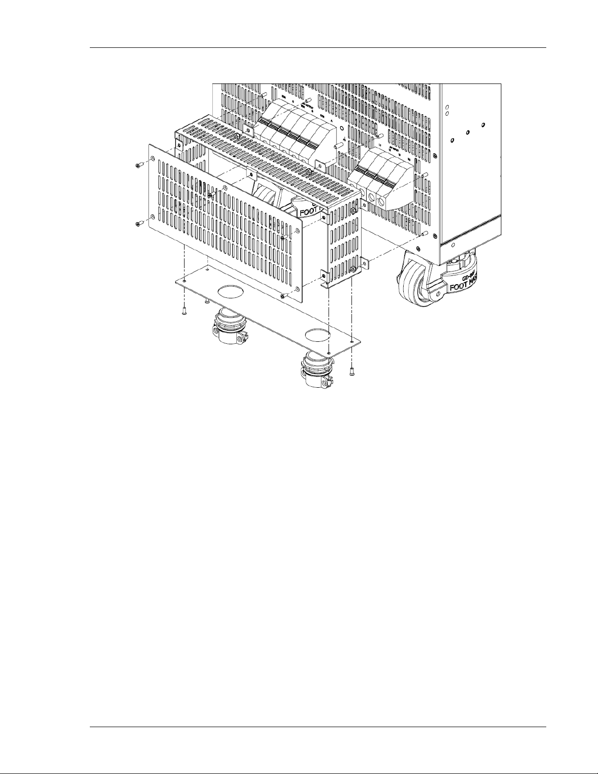
Asterion Series User Manual – 14U Models California Instruments
Figure 3-5. Rear Panel Input/Output Protective Cover Installation
M330511-01, REV-B 39
Page 40

Asterion Series User Manual – 14U Models California Instruments
Figure 3-6. Installation Drawing, Enhanced Model
40 M330511-01, REV-B
Page 41
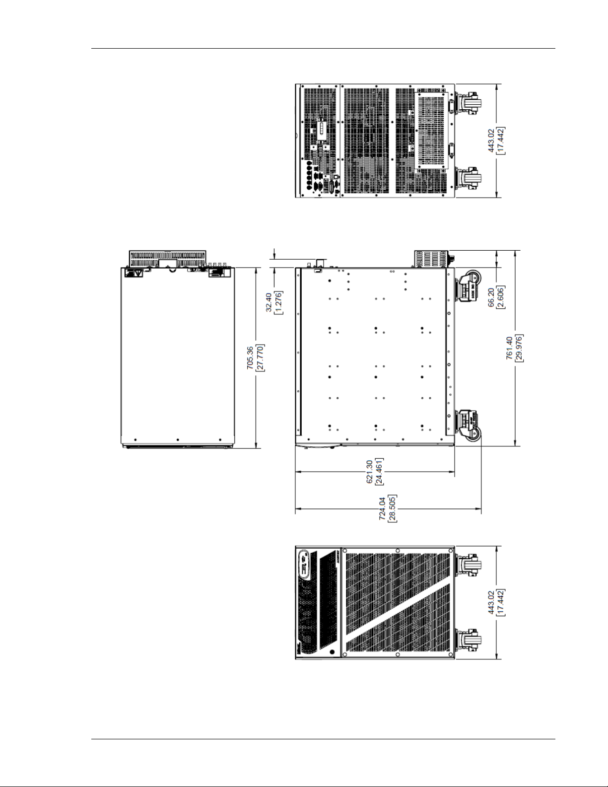
Asterion Series User Manual – 14U Models California Instruments
Figure 3-7. Installation Drawing ATE Models
M330511-01, REV-B 41
Page 42

Asterion Series User Manual – 14U Models California Instruments
3.5 Input/output Connections
Refer to Figure 3-8 for the rear panel view of the 14U Ast erion Series power source showing the location
of the input and output connectors.
Figure 3-8. Rear Panel View (with GPIB and LKM/LKS options)
42 M330511-01, REV-B
Page 43

Asterion Series User Manual – 14U Models California Instruments
WARNING!
High voltage present at rear panel poses risk of electrical shock. The input, output, and
sense covers must be installed in standalone applications to maintain protection again st
hazardous voltages. Do not remove protective covers on AC input, AC/DC output, or
output sense. Refer installation and servicing to qualified personnel.
WARNING!
The input and output voltages at the rear panel of the unit are HAZARDOUS LIVE. When
rack mounting the unit, suitable safeguards must be taken by the installer to ensure that
HAZARDOUS LIVE voltages are not operator accessible.
WARNING!
Capacitors in the power source might hold a hazard ous electrical charge even if the power
source has been disconnected from the AC mains supply. Allow capacitors to discharge
to a safe voltage before touching exposed pins of m ai ns s uppl y connector.
WARNING!
A safety disconnect device for the AC mains input must be installed so that it is readily
accessible to the operator.
WARNING!
A properly sized input overcurrent protection devi ce must be installed at the AC mains
input. It could be either a circuit breaker or fuse having a rating of 25% over t he m aximum
AC input line currents listed in the specifications of Section 2.1.3.
WARNING!
To prevent an electrical shock hazard, a safety ground wire must be connected from the
safety-ground stud on the rear panel to the AC mains earth protection-ground
3.6 AC Input Connection
The Asterion Series power source comes with two types of 3-phase input power options, as follows:
a) 3-phase, 3-wire plus ground, with nominal AC input line-line voltage of 200-240 VAC, and
50/60 Hz input frequency.
b) 3-phase, 4-wire (with neutral) plus ground, wit h nom i nal AC input voltage of
220/380 VAC - 240/415 VAC, and 50/60 Hz input frequency.
Power factor correction (PFC) provides high power factor, minimizing the required input apparent po wer
and current harmonic distortion. Refer to the specifications of Section 2.1.3 for AC input current
requirements, and derating of output power as a funct ion of AC input voltage.
3.6.1 AC Input Overcurrent Protection
The Asterion Series power source has fuses at the AC input for fault prot ect i on. These fuses are internal
to the chassis and are not user accessible. They provide fault isolation in case a failure occurs of internal
components or wiring. A suitable overcurrent protection device must be provided externally, within the
system installation, to protect the external wiring and interconnects.
M330511-01, REV-B 43
Page 44

Asterion Series User Manual – 14U Models California Instruments
3.6.2 AC Input Safety Disconnect Device
The Asterion Series power source front panel POWER switch does not disconnect the AC input line from
the unit. Ensure that an appropriately rated safety di sconnect device is incorporated in the installat i on
that will provide isolation from the AC input whe n the device is opened. The device could be a switch or
circuit breaker, and must be located close to the unit, within reach of the operator, and clearly labeled as
the disconnection device.
3.6.3 AC Input Connector
The AC input connector, AC INPUT, is located on the rear panel, along with the safety-ground stud.
a) AC Input Connection with 3-Phase, 3-Wire plus Ground
Figure 3-9 shows the rear panel view of the conne ct or and ground stud for models having an AC input
with 3-wire plus ground. Table 3-2 shows the functions an d connector pinout, and Table 3-4 the
connector type. A 3-phase, 3-wire input is connected to L1/L2/L3. The connector has compression
terminals with female contacts. A safety ground connection mu st always be made to the utility earth
protection-ground using the rear panel safety-ground stud located adjacent to the AC input connector.
CAUTION!
The maximum input voltage is 264 VAC, line-to-line, for 3-phase, 3-wire inputs.
Exceeding the maximum AC input voltage could result in damage to the unit.
Figure 3-9. AC Input Connector and Safety-Ground Stud, for 3-Wire plus Ground Input
44 M330511-01, REV-B
Page 45
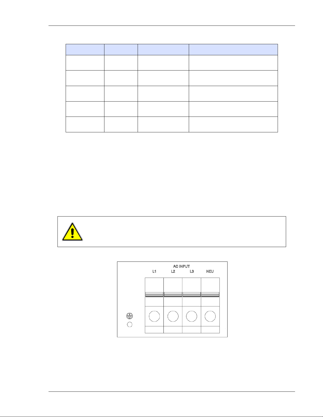
Asterion Series User Manual – 14U Models California Instruments
Name Type Range Function
AC INPUT L1 AC Input
AC INPUT L2 AC Input
AC INPUT L3 AC Input
NC
GND
No
connection
Safety
Ground
180-264 VAC,
3-Phase, Line-Line
180-264 VAC,
3-Phase, Line-Line
180-264 VAC,
3-Phase, Line-Line
Not applicable
N/A
Line-1 input from utility AC mains
Line-2 input from utility AC mains
Line-3 input from utility AC mains
No Connection
Safety-Ground connection from ut il ity
earth protection-ground
Table 3-2. AC Input Connector Pinout and Safety-Ground, for 3-Wire plus Ground Input
b) AC Input Connection with 3-Phase, 4-Wire (with Neutral) plus Ground
Figure 3-10 shows the rear panel view of the connector and grou nd stud for models having an
AC input with 4-wire (with neutral) plus ground. Table 3-3 shows the functions and connector
pinout, and Table 3-4 the connector type. A 3-phase, 4-wire input is connected to
L1/L2/L3/NEU. The connector has compression terminals with female contact s. A safety ground
connection must always be made to the utility eart h protection-ground using the rear panel
safety-ground stud located adjacent to the AC input connector.
CAUTION!
The maximum input voltage is 457 VAC, line-to-line, for 3-phase, 4-wire inputs and
neutral conneciton is required. Exceeding the maximum AC input voltage could
result in damage to the unit.
Figure 3-10. AC Input Connector and Safety-Ground Stud, for 4-Wire (with Neutral) plus Ground
Input
M330511-01, REV-B 45
Page 46
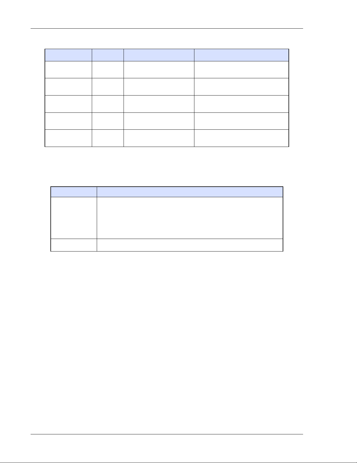
Asterion Series User Manual – 14U Models California Instruments
Name Type Range Function
AC INPUT L1 AC Input
AC INPUT L2 AC Input 197/342 VAC-264/457 VAC Line-2 input from utility AC mains
AC INPUT L3 AC Input 197/342 VAC-264/457 VAC Line-3 input from utility AC mains
AC INPUT NEU AC Input NA Neutr al input from utility AC mains
GND
Safety
Ground
197/342 VAC-264/457 VAC Line-1 input from utility AC mains
N/A
Safety-Ground connection from ut il ity
earth protection-ground.
Table 3-3. AC Input Connector Pinout and Safety-Ground, for 4-Wire (with Neutral) plus Ground
Input
Connector Type
HDFKV 50/708522; 4-position;
2
, min (6 AWG) to 50 mm2, max (1 AWG).
AC Input
Connector header: Phoenix P/N
feedthrough terminals;
wire stripping length: 24 mm (0.94”);
tightening torque: 6 Nm, min (53.1 lb-in) to 8 Nm, max (70.8 lb-in);
wire cross section: 16 mm
Safety-Ground M5-0.8 x 15 mm stud; nut tighteni ng torque, 3.8 Nm (33.6 lb-in), max.
Table 3-4. AC Input Connector Type
46 M330511-01, REV-B
Page 47
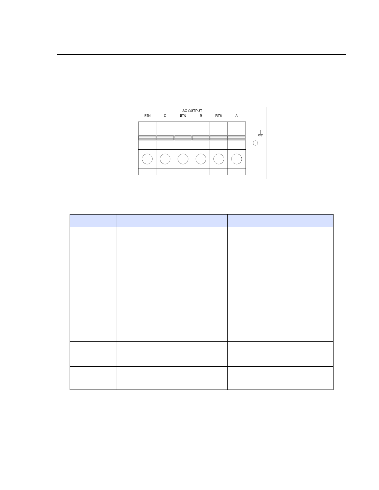
Asterion Series User Manual – 14U Models California Instruments
3.7 AC/DC Output Connection
The AC/DC Output connector provides terminations for the output connections to the load. A chassis
functional-ground connection is provided adjacent to the connector to terminate cable shields, if used.
Refer to Figure 3-11 for a view of the connector, Table 3-5 for the pinout and functions, and Table 3-6 for
the connector type.
Figure 3-11. AC/DC Output Connector and Functional-Ground
Name Type Range Function
Phase-A LINE Output
Output RTN Output
Phase-B LINE Output
Output RTN Output
Phase-C LINE Output
Output RTN Output
GND
Functional
Ground
Table 3-5. AC/DC Output Connector Pinout and Functional-Ground
0-200/400 VAC;
0 V to ±250/500 VDC
0-200/400 VAC;
0 V to ±250/500 VDC
0-200/400 VAC;
0 V to ±250/500 VDC
0-200/400 VAC;
0 V to ±250/500 VDC
0-200/400 VAC;
0 V to ±250/500 VDC
0-200/400 VAC;
0 V to ±250/500 VDC
N/A
Connection of AC/DC output Phase-A
Connection of AC/DC output return
(All the three RTN outputs are
connected together internally in the unit)
Connection of AC/DC output Phase-B
Connection of AC/DC output return
(All the three RTN outputs are
connected together internally in the unit)
Connection of AC/DC output Phase-C
Connection of AC/DC output return
(All the three RTN outputs are
connected together internally in the unit)
Connection to chassis for
functional-ground, such as termination
of cable shields
M330511-01, REV-B 47
Page 48

Asterion Series User Manual – 14U Models California Instruments
wire cross section: 16 mm2, min (6 AWG) to 50 mm2, max (1 AWG).
Connector Type
Connector header: Phoenix P/N HDFKV 50/708522; 6-position;
feedthrough terminals;
AC/DC Output
wire stripping length: 24 mm (0.94”);
tightening torque: 6 Nm, min (53.1 lb-in) to 8 Nm, max (70.8 lb-in);
FunctionalGround
M5-0.8 x 15 mm stud; nut tightening torque, 3.8 Nm (33.6 lb-in), max.
Table 3-6. AC/DC Output Connector Type and Functional-Ground
3.7.1 Output Connection for 3-Phase Load
Output connection from the Asterion Series power source to a 3-phase WYE load is shown in Figure
3-12. For a 3-phase Delta load, RTN (Return) connection is not required.
CAUTION!
1. The output connector provides three-line terminals (Phase A/B /C) and three
return terminals (RTN), each rated at 60 A.
The return terminals (RTN) are connected internally in the unit, but for total load
current greater than 60 A in the return, use indiv idual wires from each of the RTN
terminals to the load and connect them together externally.
Figure 3-12. Output Connection to 3-Phase Load
48 M330511-01, REV-B
Page 49

Asterion Series User Manual – 14U Models California Instruments
3.7.2 Output Connection for 1-Phase Load
Output connection from the Asterion Series power source to a 1-phase load is shown in Figure 3-13.
CAUTION!
The output connector provides three-line terminals (Phase A/B/C) and three return
terminals (RTN), each rated at 60 A.
1. In 1-Phase output mode of operation, all the phases (A/B / C) prov ide the same
voltage/phase. The three-line terminals of the output connector (Phase A/B/C)
are not connected internally in the unit. Use indivi dual wires from each phase
to the load and connect them together externally.
2. The return terminals (RTN) are connected internally in the unit, but for total
load current greater than 60A in the return, use indi vidual wires from each of
the RTN terminals to the load and connect them together externally.
Figure 3-13. Output Connection to 1-Phase Load
M330511-01, REV-B 49
Page 50
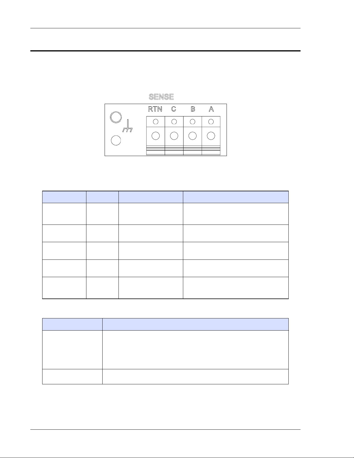
Asterion Series User Manual – 14U Models California Instruments
wire cross section: 0.2 mm2, min (24 AWG) to 6 mm2, max (10 AWG).
3.8 Remote Sense Connection
The Remote Sense connector provides terminations f or the output remote sense connections to the load.
A chassis functional-ground connection is provided adjacent to the conn ect or to terminate cable shields,
if used. Refer to Figure 3-14 for a view of the connector, Table 3-7 for the pinout and functions, and
Table 3-8 for the connector type.
Name Type Range Function
Sense-A Input
Sense-B Input
Sense-C Input
Sense RTN Input
GND
Connector Type
Figure 3-14. Remote Sense Connector and Functional-Ground
Remote sense connection for output
voltage of Phase-A or 1-Phase
output-mode
Remote sense connection for output
voltage of Phase-B
Remote sense connection for output
voltage of Phase-C
Remote sense return connection for output
voltage
Connection to chassis for
functional-ground, such as termination of
cable shields
Functional
Ground
0-400 VAC;
0V to ±500 VDC
0-400 VAC;
0V to ±500 VDC
0-400 VAC;
0V to ±500 VDC
0-400 VAC;
0V to ±500 VDC
N/A
Table 3-7. Remote Sense Connector Pinout
Phoenix P/N 0706605; 4-position;
feedthrough terminals;
Remote Sense
Functional-Ground M4-0.7 x 7 mm stud; nut tightening torque, 1.1 Nm (10 lb-in), max.
wire stripping length: 14 mm (0.55”);
tightening torque: 0.6 Nm, min (5.3 lb-in) to 0.6 Nm, max (7.0 lb-in);
Table 3-8. Remote Sense Connector Type
50 M330511-01, REV-B
Page 51

Asterion Series User Manual – 14U Models California Instruments
3.9 Remote Sense
Output voltage sensing is user-sele ct able to be either local sense or remote sense. Sensing provides the
signal for measurement of the output voltage and determines the physical point where the output voltage
is precisely regulated. Local sense is at the rear panel output connector, while remote sense is at the
load, through a cable connection from the rear panel remote sense connector. An internal relay is used
to select which sense signal is used by the controlle r.
Remote sensing is used to compensate for the voltage drop that occurs across the wires connecting the
load to the output of the power source. A separate pair of wires is routed to measure the voltage at the
terminals of the load where precise regulation of t he out put voltage is desired. The remote sense leads
are connected at the Remote Sense connector on the rear panel; refer Figure 3-14. Connect the
terminals, Sense Phase-A/B/C, to the points at the load that are connected to the Out put Phase-A/B/C
LINE terminals, and the terminal, Sense RTN, to the point at the load that is connected to Output RTN
terminal. For 1-phase mode of operation, connect only the Sense Phase-A to t he l oad.
Special care is required in routing the sensing leads to prevent noise pickup or coupling to the power
leads; refer to Section 3.10. The sense leads should be a twisted-pair of at least AWG #22 wire and may
require shielding in high noise environments. If a shield is used, connect it to the functional-ground
terminal at the AC/DC Output connector location.
If the remote sense leads are not connected, but remote sense has been selected, the AC source will
continue to operate but the voltage at the load will no l onger be precisely regulated. An internal circuit
exists within the unit that provides redundant v oltage sen sin g from the output t erminals, in case the
remote sense leads are not connected. However, this condition does not have voltage calibrat i on, and
since the voltage is now measured at the output termi nal s, t he voltage drop of the load wiring would no
longer be compensated.
Two conditions related to remote sensing are treat ed as faults and result in shutdown of the output:
short-circuiting of the remote sense terminals or connecting the remote sense leads in reverse polarity.
When the fault condition is detected, shutdown will result with the output voltage being programmed to
zero and the output isolation relays being opened.
3.10 Noise and Impedance Effects
To minimize noise pickup or radiation from load circuits, load wires and remote sense wires should be
twisted-pair and have minimum lead length. Shielding of the sense leads may be necessary in high noise
environments. Even if noise is not a concern, the load and remote sense wires should be twisted-pai rs to
reduce coupling between them, which could impa ct t he stabi l i t y of the output amplifier. Twisting the load
wires provides an additional benefit in reducing the parasitic inductance of the cable. This improves t he
dynamic response characteristics at the load by maintaining low source impedance at high frequencies.
If connectors are utilized for the power and sense leads, consideration of routing is necessary to
minimize coupling between the leads. Ensure that the connector terminals for the sense leads are in
adjacent contact locations and minimize t he physical loop area of the untwisted portions.
M330511-01, REV-B 51
Page 52

Asterion Series User Manual – 14U Models California Instruments
CAUTION!
USE, ZW
THHW, XHH, XHHW
Current Rating, A(RMS)
3.11 Wire Gauge Selection
Care must be taken to properly size all conductors f or the input and output of the power source. This
section provides guidance in the selection of wire size.
Use wire with Class B or C stranding. Fine-stranded (flexible) wire should not be used
unless crimp-on lugs or ferrules are utilized that a re approved for fine-stranded cables
3.11.1 Wire Size
The tables below will assist in determining the appropriate wire size for both the input and outpu t
connections. Table 3-9 gives minimum recommended wire size; these recommendations are for 30
ambient, and for copper wire only. This table is deriv ed from the National Electrical Code and is for
reference only. Local laws and conditions may have different requirements. For higher ratings , wires can
be paralleled; refer to the National Electrical Code f or guidelines.
Size Temperature Rating of Copper Conductor
60°C 75°C 90°C
AWG
Types: TW, UF Types: RHW,
THHW, THW,
THWN, XHHW,
Types: TBS SA,
SIS, FEP, FEPB, MI,
RHH, THHN,
°C
18 − − 14
16 − − 18
14 15 20 25
12 20 25 30
10 30 35 40
8 40 50 55
6 55 65 75
4 70 85 95
3 85 100 115
2 95 115 130
1 110 130 145
0 125 150 170
00 145 175 195
000 165 200 225
0000 195 230 260
Table 3-9. Minimum Wire Size
52 M330511-01, REV-B
Page 53

Asterion Series User Manual – 14U Models California Instruments
AWG
(90°C wire)
(One Way)
(Column 2 x Column 3)
14
12
10
3
2
1
0
When determining the optimum cable specificati on for your power applications, the same engineering
rules apply whether at the input or output of an electrical device. Therefore, this guide applies equally t o
the input cable and output cable for this power source and application loads.
Power cables must be able to safely carry maxim um l oad current without overheating or causing
insulation degradation. It is important to power source performance t o m i ni m ize IR (voltage drop) loss
within the cable. These losses have a direct effect on the quality of power delivered to and from the
power source and corresponding loads.
When specifying wire gauge, consider derating due to operating temperature at the wire location. Wire
gauge current capability and insulation performance drops with the increased temperature developed
within a cable bundle and with increased environmental temperature. Therefore, short cables with
derating of gauge size and insulation properties are recommended for power source applications.
Be careful when using published commercial utilit y wiring codes. These codes are designed for the
internal wiring of homes and buildings and accommodate the safety factors of wiring loss, heat,
breakdown insulation, aging, etc. However, t hese codes consider that up to 5% voltage drop is
acceptable. Such a loss directly detracts from the performance specifications of this power source. Also,
consider how the wiring codes apply to bundles of wire wit hi n a cable arrangement.
In high performance applications requiring high inrush/ transient currents, additional conside ration is
required. The cable wire gauge must accommodate peak currents developed at peak voltages, which
might be up to five times the RMS current values. An underrated wire gauge adds losses, which alter the
inrush characteristics of the application and thus the expected performance.
Table 3-10 presents wire resistance and resulting cable voltage drop at maximum rated current, with the
wire at 20 °C. Copper wire has a temperature coefficient of α = 0.00393Ω/°C at t1 = 20 °C, so that at an
elevated temperature, t2, the resistance would be R2 = R1 (1 + α (t2 - t1)).
The output power cables must be large enough to prevent the line voltage drop (total of both output
wires) between the power source and the load f rom exceeding the remote sense capability as pre sent ed
in the specification section. Calculate the vol tage drop using the following formula:
Voltage Drop = 2 × distance-in-feet × cable-resistance-per-foot × current
Size,
18 14 0.639 8.95
16 18 0.402 7.24
8 55 0.063 3.47
6 75 0.040 3.00
4 95 0.025 2.38
00 195 0.0078 1.52
000 225 0.0062 1.40
0000 260 0.0049 1.27
A(RMS),
25 0.253 6.33
30 0.159 4.77
40 0.100 4.00
115 0.020 2.30
130 0.016 2.08
145 0.012 1.74
170 0.0098 1.67
Ohms/100 Ft,
Voltage Drop/100 Ft,
M330511-01, REV-B 53
Table 3-10. Wire Resistance and Voltage Drop, 20 °C
Page 54
Asterion Series User Manual – 14U Models California Instruments
3.12 Rear Panel User Interface Connectors
The rear panel contains the connectors for the rem ote analog and discrete-digital control interfaces,
master/auxiliary unit interface, the digit al communications interfaces (LAN, USB, RS-232C, and optional
IEEE-488), and the external interface.
3.12.1 External Input/Output Control Signal Connector
The External Input/Output connector, EXT IN/OUT, is located on the rear panel. Figure 3-15 shows the
rear panel view of the connector, Table 3-11 lists the c onnector type. Table 3-12 shows the functions and
Table 3-13 shows the connector pinout.
Figure 3-15. External Input/Output Control Connector
Connector Type
External Input/Output Control High-density, 15-socket, receptacle (female) Subminiature-D.
Table 3-11. External Input/Output Control Connector Type
54 M330511-01, REV-B
Page 55

Asterion Series User Manual – 14U Models California Instruments
Function Characteristics
Signal inputs for output voltage waveform programming by external analog reference;
individual inputs provided for each o utput phase.
External Analog
Programming of
Output Voltage
Waveform
External Analog
Programming of
Output Voltage
Amplitude (RPV)
External Analog
Modulation of
Output Voltage
Trigger Input
Synchronization
Signal (SYNC)
Input
Remote Inhibit
Input
AC or DC input signals: 0V to user-select able maximum range value within ±2.5 V(PK) to
±10 V(PK), corresponding to maxi m um range of 1.77 V(RMS) to 7.07 V(RMS), for zero to
full-scale RMS output voltage; with AC waveform, from 16 Hz to 5 kHz (option dependent);
programming accuracy, ±2% of ful l-scale output;
input impedance, 40 kΩ, typical; safety isolation SELV-rated, refer enc ed to chassis;
this function has the same connector pin connection as the signal, E xternal Analog
Programming of Output Voltage Amplitude; that pin is user-selectable as to which function
is provided.
Signal inputs for output voltage amplitude programming of waveform that is set by internal
controller reference; individual inputs provided for each output phase.
DC input signal: 0V to user-selectable maximum range value within 2.5 VDC to10 VDC, for
zero to full-scale RMS of internally program m ed output voltage waveform;
programming accuracy, ±2% of ful l-scale output;
input impedance, 40 kΩ, typical; safety isolation SELV-rated, referenced to chassis;
this function has the same connector pin connection as the signal, E xternal Analog
Programming of Output Voltage Waveform; that pin is user-selectable as to which function
is provided.
Signal input for output voltage m odulation of waveform set by interna l controller reference;
individual inputs provided for each o utput phase.
AC or DC input signal range: 0V to ±7.07 V(PK), 0-5 V(RMS) for 0-20% of full-scale output
voltage amplitude modulation;
programming accuracy, ±2% of ful l-scale output;
input impedance, 40 kΩ, typical; safety isolation SELV-rated, referenced to chassis.
Signal input of external trigger for execution of programmed values or transient lists;
logic level, TTL-compatible;
isolated connection with signal return common to the signals, Synchr onization Signal and
Remote Inhibit; safety isolatio n SELV-rated, referenced to ISO_COM (refer to Table 3-13).
Signal input for external square wave to control the output frequency and phase, with the
waveform generated by the internal reference;
logic level, TTL-compatible; logic-high-going edge synchronized with positive-going
alternation of output waveform;
isolated connection with signal return common to the signals, Trigger Input and Remote
Inhibit; safety isolation SELV-rated, referenced to ISO_COM (refer to Table 3-13).
Signal input to turn the output off/on; logic level, TTL-compatible; user-selectable for
active-high or active-low;
isolated connection with signal return common to the signals, Synchr oni zation Clock and
Trigger Input; safety isolation S E LV-rated, referenced to ISO_COM ( refer to Table 3-13).
Switch output indicating that a Summary Fault (DFI) condition is present;
normally-closed, bidirectional AC/DC solid-state switch;
Summary Fault
Switch Output
closed-circuit for fault or when unit is turned off (open-circuit for no fault present);
switch ratings: ±12V, maximum peak voltage; 0.1A, maximum current; 2.5Ω, maximum
closed resistance; 6µA, maximum open-circuit leakage current at 12V;
connection isolated from all ot her signals, floating switch output;
safety isolation SELV-rated.
Table 3-12. External Input/Output Control Functions
M330511-01, REV-B 55
Page 56

Asterion Series User Manual – 14U Models California Instruments
Analog programming signal input terminal for useramplitude control (RPV) for Phase-A.
Analog programming signal input terminal for usercontrol (RPV) for Phase-B.
Analog programming signal input terminal for usercontrol (RPV) for Phase-C.
Isolated signal return terminal for signals on Pin-12 and
isolated from Pins1-8 and Pins14-15.
Isolated signal for synchronization of the output to a
isolated from Pins1-8 and Pins14-15.
Isolated signal return for synchronization of the output;
isolated from Pins1-8 and Pins14-15.
Isolated inhibit signal to turn the output off/on and
isolated from Pins1-8 and Pins14-15.
Pin # Name Type
1 REFERENCE-A
2 REFERENCE-B
3 REFERENCE-C
REFERENCE
4
RETURN
5 MODULATION-A
6 MODULATION-B N/A N/A External modulation signal input terminal for Phase-B.
7 MODULATION-C N/A N/A External modulation signal input terminal for Phase-C.
MODULATION
8
RETURN
9 ISO_COM Return Return
10 SYNC_HIGH
Analog
Input
Analog
Input
Analog
Input
Signal
Return
Analog
Input
Signal
Return
Digital
Input
Rang
±10V
±10V
±10V
Return Analog programming signal return terminal.
±7.07V External modulation sign al i nput terminal for Phase-A.
Return External modulation signal return terminal.
0-5V
selectable external waveform programm in g or
selectable external waveform programming or amplitude
selectable external waveform programming or amplitude
Pin-13; connected to Pin-11 through 10 Ω;
logic-high signal transition; paired with Pin-11;
Function
11 SYNC_LOW Return Return
12 INHIBIT
13 TRIGGER
SUMMARY
14
FAULT-1
SUMMARY
15
FAULT-2
Digital
Input
Digital
Input
Switch
Output
Switch
Output
Table 3-13. External Input/ Output Control Connector Pinout
0-5V
0-5V
±12V
±12V
paired with Pin-10; connected to P in-9 through 10 Ω;
open/close the output relay; signal r eturn on Pin-9;
Isolated trigger signal; signal return on Pin-9;
isolated from Pins1-8 and Pins14-15.
Isolated Summary Fault (DFI) signal; pai red with Pin15; isolated from Pins1-13; refer to
Isolated Summary Fault (DFI) signal return; paired with
Pin-14; isolated from Pins1-13; refer to
Table 3-12.
Table 3-12.
56 M330511-01, REV-B
Page 57

Asterion Series User Manual – 14U Models California Instruments
3.12.2 Summary Fault Signal (DFI)
The Summary Fault (DFI) signal, SUMMARY FAULT-1 (Pin-14) and SUMMARY FAULT-2 (Pin-15),
provides an indication of abnormal conditi on occurrence. In the default configuration, the signal reports
the summary bit that is the logic-OR of the Questi onable Status Register outputs for the following ev ents:
a. PFC Module fault: summary state of overtemperature, input undervoltage, overload;
b. DC Module fault: summary state of overtemperature, output overvoltage, driver fault;
c. AC Module fault: summary state of overtemperature, DC bus under/overvoltage, inverter
peak current limit, logic power undervoltage;
d. Overtemperature fault: AC Module overtemperature, PFC Module Over temperature, DC-DC
Module Over temperature;
e. Output overvoltage fault;
f. Output voltage regulation fault;
g. Output current-limit fault.
h. Fan Fault
The functionality of the Summary Fault signal co ul d be programmed through SCPI commands to report
events as captured in either of the following sources: Quest i onable Status Register (default setting),
Operation Status Register, Standard Event Status Register, or Request Service Summary Bit. Also, the
Summary Fault signal operation could be enabled an d di sabled through SCPI commands. Refer to the
Asterion Series SCPI Programming Manual, M3301 00-01, for specific information on the programming
options; it is referred to as the Discrete Fault Indicato r (D F I) signal in that manual.
3.12.3 Remote Inhibit Signal
The Remote Inhibit signal, /INHIBIT_ISO (Pin-12), can be used to turn the output on/off and close/open
the output relay of the power source. When set to t he of f state, this input overrides the output state
programmed through the front panel or the remote digital interface.
The default logic-level for Remote Inhi bit is a l ogi c-low or contact closure between /INHIBIT_ISO (Pin-12)
and ISO_COM (Pin-9). This will cause the output voltage to be programmed to zero volts and the output
relays to open. This logic-level c ould al so be s elect ed wit h the S CPI com ma nd, OUTPUT:RI:LEVEL LOW.
Alternatively, the logic-level could be changed by the user to logic-high using the remote digital interface
SCPI command, OUTPUT:RI:LEVEL HIGH. A logic-high or open-circuit between /INHIBIT_ISO (Pin-12) and
ISO_COM (Pin-9) will cause the output voltage to be programmed to zero volts and the output relays to
open.
The mode of operation of the Remote Inhibit can be changed using the remote digital interface SCPI
command, OUTP:RI:MODE <mode>. The following modes can be selected:
LATC(hing) A TTL logic-low (or user-selected logic-high) at the Remote Inhibit input latches
the output in the protection shutdown state; this state could only be cleared by
the remote digital interface SCPI command, OUTPut:PROTection:CLEar.
LIVE The output state follows the state of the Remote Inhibit input. A TTL logic-low (or
user-selectable logic-high) at the Remote Inhibit input t urns the output off; a TTL
logic-high (or user-selectable logic-low) turns the output on.
OFF The power source ignores the Remote Inhibit input.
The Remote Inhibit output mode state is saved at po wer-down. The factory default state is LIVE. For
additional information on programming the Remote Inhibit function, refer to the Asterion Programming
Manual P/N M330100-01 distributed on the CD, CIC496.
M330511-01, REV-B 57
Page 58

Asterion Series User Manual – 14U Models California Instruments
wire cross section: 0.2 mm2, min (24 AWG) to 0.5 mm2, max (20 AWG).
1 & 2
3.12.4 External Relay Interface
The External Relay Interface rear panel connector is shown in the Figure 3-16, Table 3-14 shows
connector type, and Table 3-15 shows the connector pinout.
The External Relay Interface provides a control signal interface with an isolated relay contact to indi cat e
the 1-Phase output mode of operation; refer to Figure 3-17 for an example of utilization of the signal
interface, and note the following considerations r eferenced in the figure:
1. The External Relay Interface relay contacts could be used to control an external relay that would
connect together the three output lines (Phase A/B/C) when the unit is set for 1-Phase output
mode of operation. This provides a means to automatically change the output configuration
between 3-Phase and 1-Phase modes.
2. The return terminals (RTN) are connected together internally in the unit, but for total load curre nt
greater than 60 A in the return, use individual wir es f rom each of the RTN terminals to the load
and connect them together externally.
Figure 3-16. External Relay Interface Connector
Connector Type
Connector: Molex P/N 43045-0614; 6-position (two used);
External Relay
Interface
Mating connector: Molex P/N 43025-0600 (AMETEK P/N 856-429-06);
6-position (two used), crimp female terminals;
Crimp terminals: Molex P/N 43030-0001 (AMETEK P/N 856-030-01);
Table 3-14. External Relay Interface Connector Type
Pin # Name Description
No Connection N/A
3 & 6 Isolated Relay Contact Contact closure occurs when 1-Phase mode of
operation is set in the Asterion power source.
Contact Rating: 250 VAC/ 30 V DC, maximum,
and 2 A, maximum.
4 & 5 No Connection N/A
Table 3-15. External relay interface Connector Pinout.
58 M330511-01, REV-B
Page 59
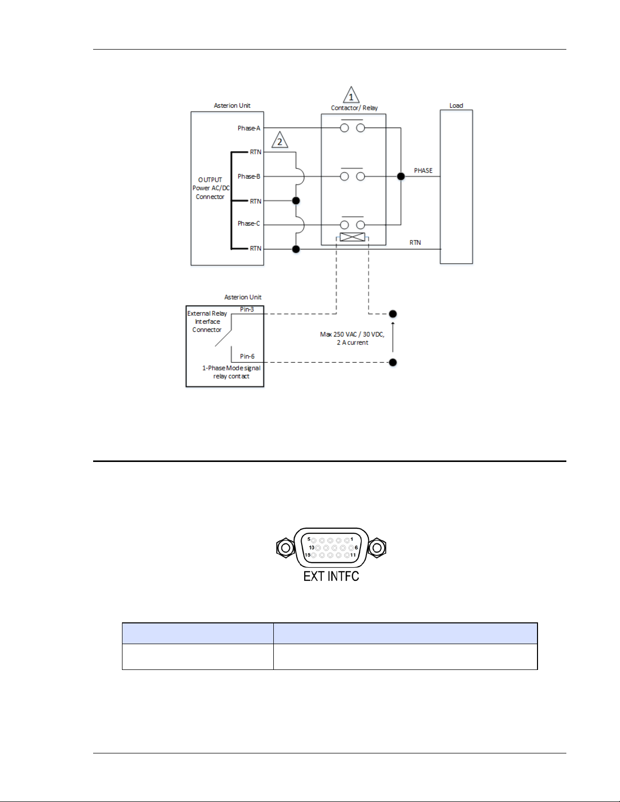
Asterion Series User Manual – 14U Models California Instruments
Figure 3-17. External Relay Interface for 1-Phase Relay Con tr ol
3.12.5 External Interface Signal Connector
The External Interface connector, EXT INTFC, is located on the rear panel Figure 3-18 shows the rear
panel view of the connector, and Table 3-16 lists t he connector type. This connector provides a
dedicated interface with an extension chassis and does n ot have any signals that are to be utilized by the
user.
Figure 3-18. External Interface Signal Connector
Connector Type
External Interface High-density, 15-socket, receptacle (female) Subminiature-D.
Table 3-16. External Interface Signal Connector Type
M330511-01, REV-B 59
Page 60

Asterion Series User Manual – 14U Models California Instruments
3.12.6 Command Monitor and Trigger Output Connectors
The connectors for the Command Monitors, CMD MO N-A, CMD MON-B, CMD MON-C, and Trigger
Output, TRIG, signals are BNC-type located on the rear panel; ref er to Figure 3-19 for view of connectors
and Table 3-17 for descriptions. The CMD MON connectors provide signal outputs for sensing the
waveforms of the internal voltage command signals that are being applied to the power amplifiers of the
three output phases. The TRIG connector provides a signal output synchronized with changes in
programmed value or transient lists.
Figure 3-19. External Command Monitor and Trigger Output Connectors
Function Characteristics
Signal outputs for monitoring the waveforms of the voltage command
Output Command
Monitor-A, Monitor-B,
Monitor-C
Trigger Output
signals of the output amplifiers; individual outputs are provided for
each output phase.
0 -5 V(RMS), typical, signal range for zero to full-scale output voltage;
individual rear panel BNC connector;
safety isolation SELV-rated, referenced to chassis.
Signal output with dual function: user-selectable as either function
trigger or list trigger; functio n trigger provides a pulse for any
programmable change in output voltage or frequency; list trigger
provides a pulse if programmed as par t of list transients;
logic level, active-low pulse with duration of 550 µs, typical;
individual rear panel BNC connector;
safety isolation SELV-rated, referenced to chassis.
Table 3-17. External Command Monitors and Trigger Output Characteristics
3.12.7 Clock and Lock Connectors (Option)
The connectors for the Clock signal, CLOCK, and Lock signal, LOCK, are BNC-type located on the rear
panel; refer to Figure 3-20 for view of connectors and Table 3-18 for descriptions. These connectors are
only available with the LKM or LKS options. These options are used to synchronize and control the
phase shift of the output voltage of Auxiliary power sources in relation to the output of the Master power
source. The frequency of the Auxiliary power sources is determined by the frequency of the Master
source through the CLOCK signal; the phase is determined by the LOCK signal. Figure 3-26 shows an
example of CLOCK and LOCK connections in a multi-phase system comprised of three power source s.
Figure 3-20. External Clock/Lock Interface Connectors (Option)
60 M330511-01, REV-B
Page 61

Asterion Series User Manual – 14U Models California Instruments
Function Characteristics
Signal outputs in Master unit for Clock and Lock that are used to synchronize two or more
LKM (Option)
LKS (Option)
AC sources; CLOCK sets the frequency, while LOCK sets the phase; logic level,
TTL-compatible; individual rear panel B N C connectors for each signal; safety isolation
SELV-rated, referenced to chassis.
Signal inputs in Auxiliary units for Clock and Lock that are used to synchronize two or more
AC sources; CLOCK sets the frequency, while LOCK sets the phase; logic level,
TTL-compatible; individual rear panel B N C connectors for each signal; safety isolation
SELV-rated, referenced to chassis.
Table 3-18. External Clock/Lock Interface Chara cteristics (Option)
3.12.8 Master/Auxiliary System Interface Connectors
The Master connector, MASTER, and Auxiliary connector, AUXILIARY, are used to connect Auxiliary
power sources to the Master power source for operation in parallel, multi-chassis systems; refer to
Figure 3-21 for view of connectors, with Table 3-19 and Table 3-20 for descriptions. The Master/Auxiliary
interface signals are dedicated to the control of parallel-group operation and are not to be utilized by the
user.
The power source that is to be the Master will have the System Interface cable plugged into its connector
labeled MASTER. The other end of the System Interface cable will plug into the connector labeled
AUXILIARY in the first Auxiliary power source com prising the system. Additional Auxiliary power so urces
would be chained together with System Interfac e cables connecting the MASTER connector of one unit
to the AUXILIARY connector of the next unit in the chain. Refer to Figure 3-25 for an example of a
parallel system comprised of three units.
Figure 3-21. External Master/Auxiliary System Interface Connectors
Connector Type
Master High-density, 26-pin, plug (male) Subminiature-D.
Auxiliary High-density, 26-socket, receptacle (female) Subminiature-D.
Table 3-19. External Master/Auxiliary System Inte rface Connector Type
M330511-01, REV-B 61
Page 62

Asterion Series User Manual – 14U Models California Instruments
1
5
Common
N/A
N/A
6
7
8
9
Function Characteristics
Control signal interface on Master unit (or other Auxiliary unit i f more
than two units comprise the parallel-group) going to Auxiliary u nit for
Master Interface
Auxiliary Interface
multi-chassis parallel operation;
Connector: high-density, 26-pin, male Subminiature-D; none of the
signals are intended for interfa c e with user equipment.
Control signal interface on Auxil iary unit coming from Master unit (or
other Auxiliary unit if more than two units comprise the parallel-group)
for multi-chassis parallel operation;
Connector: high-density, 26-socket, female Subminiature-D; none of the
signals are intended for interfa c e with user equipment.
Table 3-20. External Master/Auxiliary System Interface Charac teri stics
3.12.9 RS-232C Serial Interface Connector
RS-232C remote control interface is made through a 9-contact Subminiature-D c onnector located on the
rear panel; refer to Figure 3-22 for view of connector and Table 3-21 with Table 3-22 for descriptions.
The power source functions as Data Circuit-terminating Equipment (DCE). The cable connecting t o t he
Data Terminal Equipment (DTE) should be straight-through (one-to-one contact connections).
Figure 3-22. RS-232C Interface Connector
Connector Type
RS-232C Interface 9-contact receptacle (female) Subminiature-D.
Table 3-21. RS-232C Interface Connector Type
Pin # Name DCE Signal Direction
N/C N/A N/A
2 TxD Transmit Data Output
3 RxD Receive Data Input
4 N/C N/A N/A
N/C N/A N/A
RTS Request To Send Input
CTS Clear To Send Output
N/C N/A N/A
Table 3-22. RS-232C Interface Connector Pinout
62 M330511-01, REV-B
Page 63
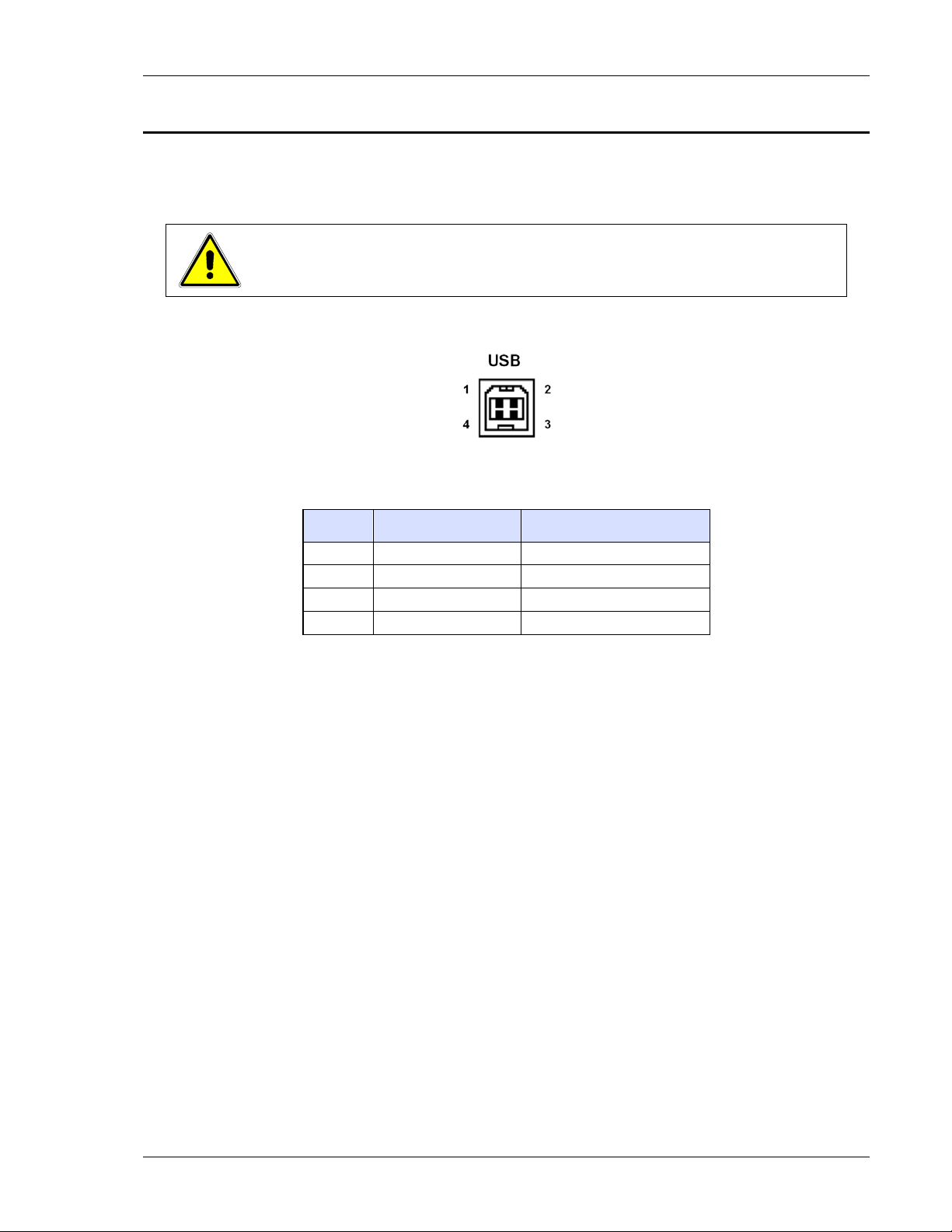
Asterion Series User Manual – 14U Models California Instruments
3
4
3.12.10 USB Interface
USB remote control interface is made through a Series-B device connector located on the rear panel;
refer to Figure 3-23 for view of connector and Table 3-23 for descriptions. A standard USB cable
between the Asterion Series power source and a computer should be used.
.
CAUTION!
Connecting the power source to the computer controll er t hrough an USB hub is not
recommended. The USB connection should be dire ct bet ween the two devices.
Figure 3-23. USB Interface Connector
Pin # Name Description
1 N/C No C onnection
2 D- Data -
D+ Data +
GND Ground
Table 3-23. USB Interface Connector Pinout
M330511-01, REV-B 63
Page 64

Asterion Series User Manual – 14U Models California Instruments
Crossover
5
6
3.12.11 LAN Interface (Ethernet)
A LAN connector (Ethernet 10BaseT/100BaseT) is lo cated on the rear panel for remote control; refer to
Figure 3-24 for view of connector and Table 3-24 for descript ions. A standard modular cable with an
8P8C modular plug should be used between the power source and a network hub. For a direct
connection to a computer LAN card, a crossov er cable with an 8P8C modular plug is required. The MAC
Address (Media Access Control) of the Ethernet port i s printed on a label on the chassis of the power
source. For information on how to set up a network connection or a direct computer connection using the
LAN interface, refer to the Asterion Series Programming Manual P/N M330100-01 distributed on the CD,
CIC496.
Figure 3-24. LAN Interface 8P8C Modular Connector
Pin # Ethernet Signal EIA/TIA 568A
1 Transmit/Receive Data 0 + White with green stripe White with orange stripe
2 Transmit/Receive Data 0 -
3 Transmit/Receive Data 1 + White with orange stripe White with green stripe
4 Transmit/Receive Data 2 + Blue with white stripe or
Transmit/Receive Data 2 - W hite with blue stripe White with blue stripe
Transmit/Receive Data 1 -
7 Transmit/Receive Data 3 + White with brown stripe or
8 Transmit/Receive Data 3 - Brown with white stripe or
Table 3-24. LAN Interface 8P8C Modular Connector Pinout
Green with white stripe or
solid green
solid blue
Orange with white stripe or
solid orange
solid brown
solid brown
EIA/TIA 568B
Orange with white stripe or
solid orange
Blue with white stripe or
solid blue
Green with white stripe or
solid green
White with brown stripe or
solid brown
Brown with white stripe or
solid brown
64 M330511-01, REV-B
Page 65

Asterion Series User Manual – 14U Models California Instruments
3.13 Multiple Chassis System Configurations
The Asterion Series power source has the capability t o be conf i gured in multi-chassis groups with
multiple-phase outputs using the optional Clock/Lock signal interface. The sources are individually
programmed for output voltage/current, while the Clock/Lock interface ensures frequency and phase
synchronization between units.
The power source could also be configured in parallel, multiple-chassis groups to extend the total output
power. The outputs of the individual units must be connected in parallel, and a Master/Auxiliary System
interface cable must interconnect them. The control interface of the units is automatically configured
when the Master/Auxiliary System interface cable is connected, so no setting changes by the user are
required.
3.13.1 Multi-Phase System
The connections to set up a multi-phase group of units require that the output lines, PHASE-A,
PHASE-B, PHASE-C, and RTN, are connected independently from each o ut put of a unit to the load. If
the remote sense is used, each unit must have it connect ed to the phase of the load at the point where
precise regulation of the output voltage is desired.
The units must have the Clock/Lock options installed, with the Master unit having the LKM option and the
Auxiliary units having the LKS option. The Clock/Lock conne ct ors of the Master unit provide output
signals: CLOCK to set the frequency, and LOCK to set the phase. The Clock/Lock connectors of the
Auxiliary units are inputs to accept the control signals from t he M aster unit. The Clock and Lock
interfaces are signal buses, so the Clock connectors of all units must be connected, and the Lock
connectors must be connected together. P rogramming, readback, and control are done through the
individual units. Also, the Auxiliary units must have their phase programmed in reference to the Master
unit. Refer to Figure 3-26 for an example configuration.
The clock source and configuration must be set for m ulti-phase operation through the remote digital
interface using SCPI commands or the front panel display. Set up through the front panel is as follows:
1. In the CONFIGURATION, PONS CLOCK CONFIG display menu, the Master unit must have the
configuration set to Master (the AC input must be cycled off/on for a change in a PONS setting to
take effect); refer to Section 4.6.5;
2. In the CONFIGURATION, PONS CLOCK CONFIG display menu, the Auxiliary units must have
the configuration set to Auxiliary (the AC input must be cycled off/on for a change in a PONS
setting to take effect); refer to Section 4.6.5;
3. In the CONFIGURATION, CLOCK MODE display menu, the Auxiliary units must have the clock
source set to External; refer to Section 4.6.5.
3.13.2 Parallel System
The connections to set up a parallel group of units requi re t hat the output lines PHASE-A, PHASE-B,
PHASE-C and RTN are connected together from each unit to an external terminal block. If the remote
sense is used, only the Master unit has it connected to the load at the point where precise regulation of
the output voltage is desired; the Auxiliary unit does not have remote sense connected. The
Master/Auxiliary System Interface cable is conne ct ed from the Master unit connector, MASTER, to the
Auxiliary unit connector, AUXILIARY. Refer to Figure 3-25 for an example configuration.
The aggregate output power of the parallel group would be sum of the individual ratings of the 14U
Asterion Series models connected in parallel. M aximum aggregate power allowed by paralleling 14U
Asterion power sources is limited to 36 kW.
M330511-01, REV-B 65
Page 66

Asterion Series User Manual – 14U Models California Instruments
The Master/Auxiliary interface is automat icall y configured so that the current reported by the Mast er unit
is the sum of all units within the group. The display of the Auxiliary unit is disabled, and shows the
message, “SOURCE IN AUXILIARY MODE No access to the user”.
When the parallel group system is powered up, the order of powering the Auxiliary source and the
Master source is not important. After the system is powered up, if an Auxiliary power source is powered
down there will be an error message displayed on the M aster source, “Aux Down ensure all are powered
up”. If power is reapplied to the Auxiliary source, the message will disappear, and normal operation could
resume. If the Master/Auxiliary System Interf ace cable is removed from the Auxiliary source while t he
source is powered down, the error message will disappear, but the Master source will not have the
correct configuration. The Master source must have its AC input power toggled, Off to On, for the correct
configuration to be re-established.
66 M330511-01, REV-B
Page 67
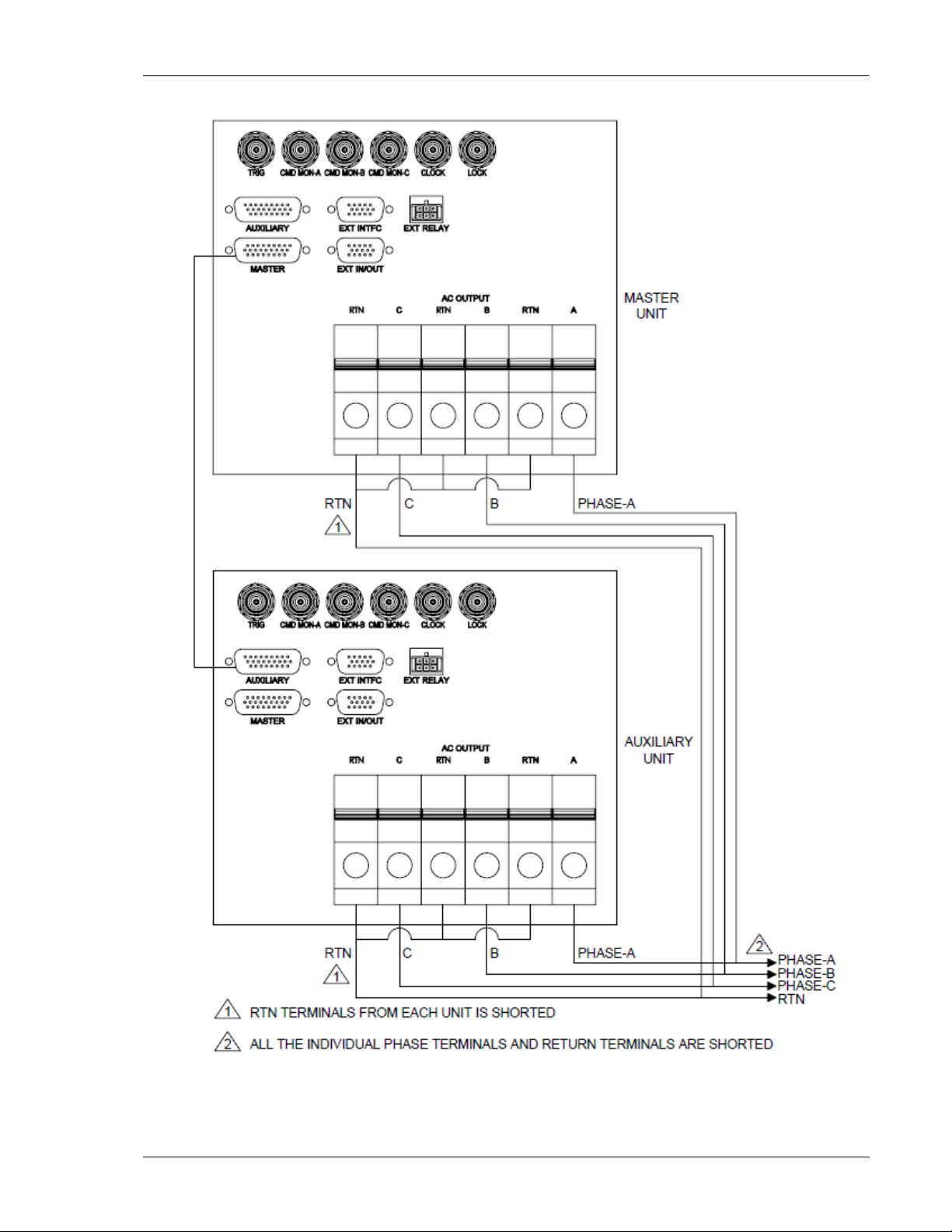
Asterion Series User Manual – 14U Models California Instruments
Figure 3-25. Connections for 3-Phase Parallel Group
M330511-01, REV-B 67
Page 68

Asterion Series User Manual – 14U Models California Instruments
Figure 3-26. Connections for 3-Phase Master/Auxiliary Multi-Phase Group
68 M330511-01, REV-B
Page 69
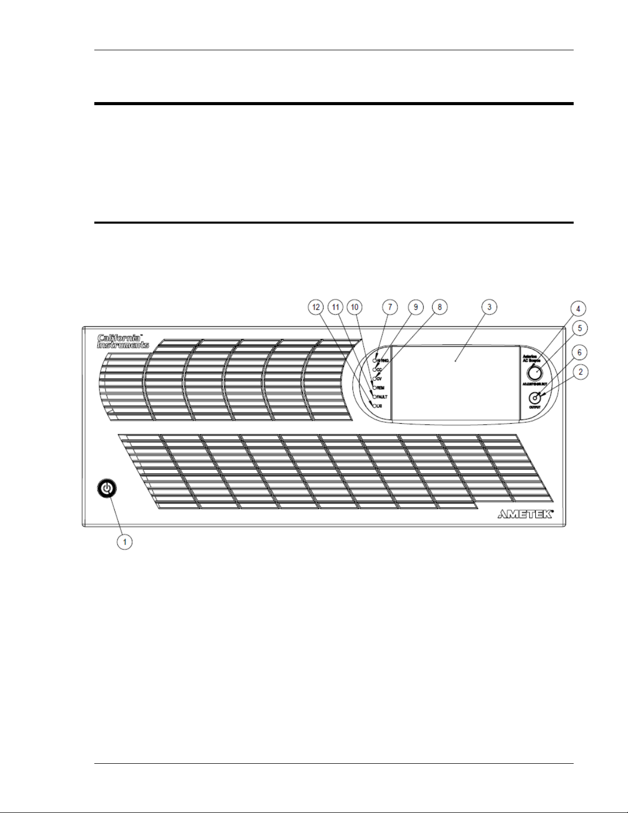
Asterion Series User Manual – 14U Models California Instruments
4. Operation
The Asterion Series power source provides extensive functionality and programmability, which could be
utilized through the front panel, remote digital interface, and the remote analog/digital control interface.
The front panel includes a graphical, touch-screen display utilizing a menu-driven interface for simplified
operation of the unit and quick access to the sophisticated functions. The remote interfaces provide
expanded control capability and access to the f ul l functionality of the source. The following sections
provide detailed information on the controls and indicators, front panel menu structure, and remote digital
interface programming conventions.
4.1 Front Panel Operation
Figure 4-1 shows a view of the front panel of the Enhanced models, while Figure 4-2 shows the front
panel of the ATE models. Refer to Table 4-1 for functional descriptions of the Enhanced front panel, and
Table 4-2 for functional descriptions of the ATE front panel.
Figure 4-1. Front Panel, Enhanced Models
M330511-01, REV-B 69
Page 70
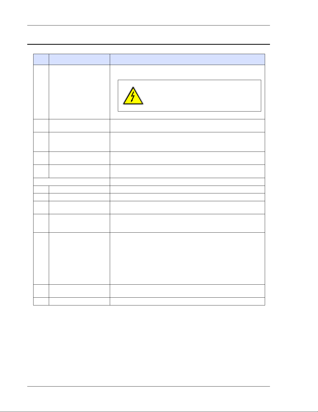
Asterion Series User Manual – 14U Models California Instruments
closes/opens the output isolation relay.
LED Mode Indicators
6
12
4.1.1 Front Panel Controls and Indicators, Enhanced Models
Item
Reference Functional Description
Two–position pushbutt on switch turns the source on and off.
1 ON/OFF(Standby) Switch
2 OUTPUT Switch
Momentary switch that toggles the output power ON/OFF, and
OFF position does not remove AC input from
internal circuits. Disconnect external AC input before
servicing unit
TFT color graphics display with back light and pressure-actuated
WARNING!
3 Display
touch-screen;
menu-driven settings and functions.
4 Rot ary Encoder
5 Rot ary Encoder Switch
Navigates between and within screens; scrolls through functions and
selects numerical values; adjust s output parameters in real-time.
Momentary-action switch that selects functions and enters numerical
values.
Indicates the mode that is active:
OUTPUT Output is turned on; indicator is integral with the OUTPUT switch.
7 HI RNG The output voltage is set to the high-range.
8 CV
All output phases of the power source are presently in Constant-Voltage
mode, and the output voltage is regul ated.
At least one of the output phases of the power source is pres ently in
9 CC
Constant-Current mode, and the output current of that output is
regulated.
Source is presently controlled by the remote digital interface. If the
RS-232C, USB or LAN interface is used, the REM state can be enabled
by the external controller using t he S C P I command, SYST:REM. If the
optional IEEE-488 (GPIB) interface is used, this indicator will be lit
10 REM
whenever the REM line (REM ENABLE) line is asserted by the IEEE-488
controller.
Any time the REM LED is lit, the front panel control of the unit is
disabled. To regain control throug h the front panel, the external controller
must send the SCPI command, SYST:LOC.
11 FAULT
Fault condition has occurred; output is shutdown, isolation relay is open,
and output voltage is programmed to zer o.
LXI LXI status annunciation.
Table 4-1. Front Panel Controls and Indicators, Enhanced Models
70 M330511-01, REV-B
Page 71

Asterion Series User Manual – 14U Models California Instruments
4.1.2 Front Panel Controls and Indicators ATE Models
Figure 4-2. Front Panel, ATE Models
M330511-01, REV-B 71
Page 72

Asterion Series User Manual – 14U Models California Instruments
LED Mode Indicators
5
Item Reference Functional Description
Two–position pushbutton switch turns the s ource on and off.
1 ON/OFF(Standby) Switch
2 UPDATE Switch
3 POWER AC input power is turned on to the unit.
4 OUTPUT Output is turned on.
HI RNG The output voltage is set to the high-range.
6 FAULT
7 CC
8 CV
9 REM/LAN
Momentary switch that enables the boot-loader when it is depressed
while the unit is being powered on with the AC input.
Indicates the mode that is active:
Fault condition has occurred; output is shutdown, isolation relay is
open, and output voltage is programmed to zero.
At least one of the output phases of the power source is pres ently in
Constant-Current mode, and the output current of that output is
regulated.
All output phases of the power source are presently in Constant-Voltage
mode, and the output voltage is regul ated.
Source is presently controlled by the remote digital interface.
If the RS-232C, USB or LAN interface is used, the REM state c an be
enabled by the external controller using the SCPI command,
SYST:REM. If the optional IEEE-488 (GPIB) interfac e is used, this
indicator will be lit whenever the RE M line (REM ENABLE) line is
asserted by the IEEE-488 controller .
Any time the REM/LAN LED is lit, the front control of the u nit is
disabled. To regain control through the front panel, the external
controller must send the SCPI command, SYST:LOC.
With LAN interface, the REM/LAN indi c ator also provides LXI status.
WARNING!
OFF position does not remove AC input from
internal circuits. Disconnect external AC input before
servicing unit.
Table 4-2. Front Panel Controls and Indicators, ATE Models
72 M330511-01, REV-B
Page 73

Asterion Series User Manual – 14U Models California Instruments
4.2 Basic Output Programming
For basic operation, the power source requires selection of the output phase number (1-Phase or
3-Phase), output phase angle, output voltage mode (AC, DC, or AC+DC), voltage range (Low-Range or
High-Range), the mode of operation (CV/CC or CV/CL modes ), and adjustment of the output parameters
(voltage, current, frequency, phase, and DC offset). This could be accomplished through the front panel
display by navigating to the appropriate menu, entering the desired values, and enabling the output;
alternately, the remote digital interface could be used with SCPI commands (refer to the Asterion Series
Programming Manual P/N M330100-01 distributed on the CD, CIC496) or the Asterion Virtual Panels
GUI; refer to AMETEK PPD website, www.powerandtest.com
4.2.1 Front Panel Display Navigation
The selection of the output characteristics and adjusting the output parameters through the front panel
display could be accomplished using the DASHBOAR D screen (refer to Figure 4-13) or the OUTPUT
PROGRAM screen (refer to Figure 4-16). The selection and adj ustment of items could be done using
either the touch-screen or rotary encoder:
1. Using the touch-screen or rotary encoder, navi gate (refer to Section 4.5.1 and Section 4.5.2) to
the HOME Screen, and select the OUTPUT PROGRAM sc reen (refer to Figure 4-16).
2. Within the OUTPUT PROGAM screen, select t he parameter, and adjust its value.
3. The DASHBOARD screen provides an alternate means of adjusting the primary parameters,
voltage, current, and frequency, in the same menu. It is also located in HOME Screen. It has the
additional functionality of real-time adjustment of the parameters as the encoder is rotated (refer
to Section 4.6.1.1).
, to download latest version.
4.2.2 Selecting Output Characteristics and Adjus ti ng Parameters
To set up the power source for basic operation with either a sine wave or DC output, perform the
following sequence:
1. Navigate to the PHASE NUMBER menu in the OUTPUT PROGRAM screen and select the
output phase number: either One-Phase or Three-Phase.
2. Navigate to the PHASE menu in the OUTPUT PROGRAM screen, and select the output phase
angle: Phase-B and Phase-C relative to Phase-A.
3. Navigate to the Voltage Mode menu in the OUTP UT PROGRAM screen, and select the output
voltage mode: either AC, DC, or AC+DC.
4. Navigate to the VOLTAGE RANGE menu in the OUTPUT PROGRAM screen and select the
output range: either Low-Range or High-Range.
5. Navigate to the REGULATION menu in the OUTPUT PROGRAM screen, and select the output
voltage/current regulation: either CV/CC or CV/CL.
6. Navigate to the VOLTAGE menu in the OUTPUT PROGRA M screen and adjust the output
voltage value.
7. If the AC+DC voltage mode had been selected, nav i gat e to the DC OFFSET menu in the
OUTPUT PROGRAM screen, and adjust t he DC co mponent of the output voltage.
8. Navigate to the CURRENT menu in the OUTPUT PR OG RA M screen and adjust the output
current value.
M330511-01, REV-B 73
Page 74

Asterion Series User Manual – 14U Models California Instruments
9. Navigate to the FREQUENCY menu in the OUTPUT PROGRAM screen, and adjust the output
frequency value.
10. The output could be turned on with the front panel OUTPUT switch.
4.3 Basic Functional Test
.
WARNING!
When performing the functional tests, exercise appropriate care to protect
against hazardous voltages that are present on the input and output.
Basic functional test of the power source could be performed with the following steps:
1. Connect an oscilloscope and DVM to the power source AC/DC Output connector.
Recommended equipment: oscilloscope, T ekt ronix TDS 3034C with P5202A high-voltage
differential probe; DVM, Keysight 34461A.
2. With the AC mains verified as being off, make t he AC input voltage connections to the power
source input connector.
3. Turn on the AC mains, and then turn on the POWER switch on the power source front panel.
4. Verify that the front panel LCD display lights up, or, in the ATE m odel s, the POWER LED. After
several seconds the display should show the DASHBOARD Screen Top-Level Menu or the
Default screen; refer to Section 4.6 for description of menus.
5. Switch on the resistive load for each phase that is set to draw 90% of full-scale current at
200 V(RMS) for the low-range AC output.
6. Using the front panel display or remote digital int erf ace, set the output of each phase for AC
mode operation with the following parameters: voltage m ode = AC; voltage range = low, 200 V;
output voltage = 200 V(RMS); frequency = 60 Hz; and current setting = full-scale for the
particular model being tested. Ensure that the Constant-Voltage/Current-Limit mode is selected
in the REGULATION menu of the OUTPUT PROGRAM Screen Top-Level Menu; refer to
Section 4.6 for description of menus.
7. Enable the output by tapping the OUTPUT switch. The OUTPUT LED in the switch button will
turn on when the output is on.
8. Verify that the output voltage of each phase remains a sine wave within specifications for voltage
accuracy.
9. Program the output current to 50% of full-scale output current and verify that a fault condition is
generated with the output turned off, the output voltage setting at zero, and the front panel
FAULT indicator on.
10. Return the current setpoint to 100% of full-scale and set the output voltage = 200 V(RMS).
11. Enable the output with the OUTPUT switch. The OUTPUT LED in the switch button will turn on
when the output is on.
12. Verify that the output voltage of each phase returns to its setpoint.
13. Program the power source to the Constant-Voltage/Constant-Current mode through t he display
using the REGULATION menu of the OUTPUT PROGRAM Screen Top-Level Menu; refer to
Section 4.6 for description of menus.
14. Program the output current to 50% of full-scale output current and verify that the output voltage
of each phase is reduced from the setpoint, while t he out put current is regulated to its setpoint.
74 M330511-01, REV-B
Page 75

Asterion Series User Manual – 14U Models California Instruments
15. Return the current setpoint to 100% of full-scale and verify that the output voltage of each phase
returns to its setpoint.
16. Turn off the OUTPUT switch.
17. Switch on the resistive load to each phase that is set to draw 90% of full-scale current at 400
V(RMS) for the high-range AC output.
18. Repeat Steps 7 through 11, but set the AC output of each phase for the following:
voltage range = high, 400 V; output voltage = 400 V(RMS); current setting = full-scale for
particular model being tested.
19. Repeat Steps 5 through 18, but set the output of each phase for DC mode operation with the
voltage set for 250 VDC in the low-range and 500 VDC in the high range, and the load for each
phase set appropriately for the DC range selected.
4.4 Output Power Characteristic
The iX2TM Constant-Power output characteristic of the Asterion power source has a power limit that is
present in each of the two output voltage ranges (low-range and high-range) for AC and DC outputs. Ful l
rated output power is available from 100% of ful l-scal e output voltage down to 50% of full-scale output
voltage; refer to Figure 4-3 for the relation between the voltage and current follows a constant-power
curve with the limit being the rated power of the unit: The out put current increases to 200% of full-scale
output current as output voltage is reduced to 50% of full-scale output voltage. Accordingly, the power
source will automatically adjust the allowed maximum value of the programmed output current when the
output voltage is within 50% and 100% of full-scale to ensure that the power limit is not exceeded. Refer
to graphs for current rating as a function of output voltage and frequency in Figure 2-1.
TM
Figure 4-3. iX2
Constant-Power Output Characteristic
M330511-01, REV-B 75
Page 76
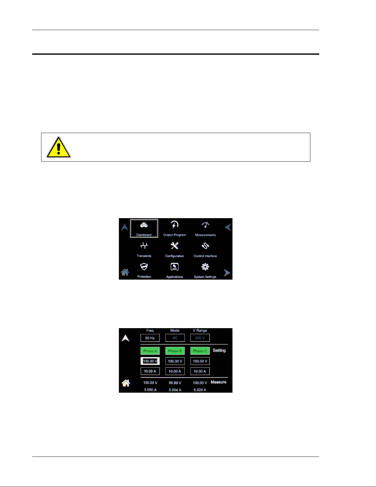
Asterion Series User Manual – 14U Models California Instruments
4.5 Front Panel Touch-Screen Display
The front panel display of the Asterion Series power source allows the user to select the various menus
required to configure and operate the unit. Navigating through the various menus could be don e using
the touch-screen display or the rotary encoder. Tapping the di splay screen or clicking with the encoder
on any menu or function that is highlighted (active) will enter that menu or execute that function.
The touch-screen utilizes resistive, pressure-actuated technology, and depends on pressure being
applied to the top surface of the screen to detect the p osition of input. A fingertip, fingernail, or stylus pen
could be used. To prevent scratching the surface layer, do not use a hard or sharp tip, such as ball-point
pen or mechanical pencil.
.
CAUTION!
Damage or scratching of the touch-screen could occur if excessive pressure is
applied to the surface, or if objects with hard/sharp t ips are used.
The present cursor position is always shown with a selection-box that has a highlighted border around a
field. Some screens have multiple pages, as indicate d by the highlighted Arrow icons located on the right
side of the screen: for example, the default HOME Screen can be scrolled through three pages. Tapping
an Arrow or selecting it with the rotary encoder and clicking the switch, scrolls the screen to the next
page. When outside one of the HOME screens, tapping the Home icon will exit that screen and return
back to the HOME screens. Refer to Figure 4-4.
Figure 4-4. HOME Screen
Parameters that are adjustable have selection-fields where values could be entered. The parameter
selection-field that is active has its border highlighted; refer to Figure 4-5 where the Dashboard Menu i s
shown with the voltage selection-field active. Tapping the selection-field box, selects that parameter for
adjustment, and the screen changes to the numeri c k eypad that allows value entry; refer to Figure 4-7.
Figure 4-5. DASHBOARD Screen Menu with Voltage Selection-Field Active
When the power source is configured for 3-Phase out put , each phase has individual settings. Clicking on
a phase button toggles selection of that phase for inputting values. When a phase is selected, its button
is displayed with a green color. When a phase is not selected, its button is display with a gray color.
76 M330511-01, REV-B
Page 77

Asterion Series User Manual – 14U Models California Instruments
When the unit is configured for 1-Phase output, only Phase-A is displayed green. When all phases are
selected, entry for one phase will make the same cha nges for the other phases. Refer Figure 4-6 to
where only Phase-A has been selected.
Figure 4-6. Menu with Only Phase-A Selected
4.5.1 Touch-Screen Numeric Keypad
The touch-screen has a keypad that allows numeric value entry; refer to Figure 4-7. After scrolling
through menus until a parameter selection-field box is highlighted (active), tapping the selection-field
selects it. Afterwards, the keypad screen will be displayed. T apping numerical value keys, the decimal
point key, or the polarity key, selects them, while the back-arrow key erases the last entry. To enter a
negative value, first enter the number then the minus sign. The selected values appear in the upper-left
parameter window, and the cursor moves to the next available position. Tapping the OK key enters the
value to have it take effect.
Figure 4-7. Touch-Screen Numeric Keypad
4.5.2 Rotary Encoder
The rotary encoder provides a secondary way to navigate the display. It is used to select functions,
change parameter values, and perform setup. It can be used to move between menu screens and
between editable items within an individual menu screen.
The rotary encoder is located on the front panel and prov i des continuous adjustment in the clockwise
and counter-clockwise rotation; refer to Figure 4-8. Turning the encoder knob allows sequential scrolling
through each menu or function on a screen; the i tem that is active has its selection field-box highlighted.
To select a choice, depress the encoder knob to engage the encoder momentary switch.
M330511-01, REV-B 77
Page 78

Asterion Series User Manual – 14U Models California Instruments
Figure 4-8. Rotary Encoder
The rotary encoder can operate in one of two distinct modes:
MODE DESCRIPTION
NAVIGATE The rotary encoder can be used to scroll through menu screen
functions and settings. The current (active) selected item will be
outlined in a highlighted selection-field box. As the encoder is
rotated, the highlighted box will be scrolled through all items on a
screen that could be selected; refer to Figure 4-9.
ADJUST/SELECT After scrolling to a function, the rotary encoder knob is depressed to
select the function (clicking on an item). Clicking on a
selection-button will change its state (on or off) and clicking on a
function or menu will select it and change to a screen that allows
further value entry.
Parameter values, such as voltage and current, are adjusted by
selecting the parameter (clicking on it) to enable the selection-field
(refer to Figure 4-9). If a parameter had been selected whose value
could be adjusted, and the encoder switch is depressed, a screen will
be displayed with a parameter selection-fiel d hi ghl ighted that has a
value entry window (refer to Figure 4-10). The rotary encoder could
then be used to continuously adjust the parameter v alue, up and
down, as the encoder is rotated. Click the encoder a second time to
enter the value. If the OUTPUT switch is on, t he output parameter
will change when the encoder is clicked.
The DASHBOARD screen menu has the capability for real-time
adjustment of output parameters: the value of the pa rameters change
as the rotary encoder is turned for immediate effect at t he out put. If
the OUTPUT switch is on, the output parameter will change as the
encoder is rotated. Refer to the DASHBOARD screen menu in
Section 4.6.1 for a description of the parameters that have real-time
adjustability.
Figure 4-9. Output Program Menu Selection-Fields with Phase Number Highlighted
78 M330511-01, REV-B
Page 79

Asterion Series User Manual – 14U Models California Instruments
3-Phase with only Phase-A selected
3-Phase with Phase-A/B/C selected
3-Phase unit in 1-Phase mode, or 1-Phase unit
Figure 4-10. Highlighted Voltage Selection-Field with Value Window
The rotary encoder could also be used with the numeri c keypad to
enter values. After selecting a parameter using the touch-screen, the
numeric keypad will be displayed; refer to Figure 4-7. The rotary
encoder could be used to select any of the items of the numeric
keypad by scrolling through them and clicking on them wit h the
encoder switch to select them. The active value is identified on the
screen with a highlighted field-box, and the entered decimal places
are shown in the upper-left window. The cursor moves to the next
available position as values are entered. After the desired decimal
places are entered sequentially, the OK key is clic ked to execute the
final value and have it take effect.
M330511-01, REV-B 79
Page 80

Asterion Series User Manual – 14U Models California Instruments
4.6 Front Panel Di splay Menus
At initial power-on, the display shows the Asterion Splash screen followed by the Start-Up screen with
the model number, serial number and firmware revisions, and finally the Default screen showing output
voltage and current values. Refer to Figure 4-11.
3-Phase Mode
1-Phase Mode
Figure 4-11. Power-On Screens
80 M330511-01, REV-B
Page 81

Asterion Series User Manual – 14U Models California Instruments
Selecting the Home icon or Up arrow will open the HOME screen of the menu structure. It is made up of
menus, as follows: DASHBOARD, OUTPUT PROGRAM, MEASUREMENTS, TRANSIENTS,
CONFIGURATION, CONTROL INTERFACE, PROTECTION, APPLICATIONS, SYSTEM SETTINGS.
Each menu of a screen could be selected by tapping its associated selection-field box through the
touch-screen, or by selecting it with the rotary encoder and depressing (clicking) the rotary encoder
SELECT switch. Refer to Figure 4-12.
Figure 4-12. HOME Screen
There are four virtual buttons visible on a screen: UP , LE F T, and RIGHT arrows, and HOME icon. Those
buttons that are highlighted are active for the particul ar screen being displayed. The arrow buttons will
scroll to the next page of the menu structure in the direction indicated. The HOME button will return to
the previous home screen that has the top-level menu f rom which a sub-menu was entered. The HOME
button is no longer functional once a home screen is entered.
The following top-level menu choices can be accessed through the touch-screen:
Top-Level Screen Menu Menu Description
Provides setting and measurem ent of output parameters:
DASHBOARD
OUTPUT PROGRAM
MEASUREMENTS
TRANSIENTS
CONFIGURATION
CONTROL INTERFACE
PROTECTION Provides setup of OVP protection supervisories.
APPLICATIONS
SYSTEM SETTINGS
voltage, current, frequency, and voltage range. Provides
automatic transition to Default screen.
Provides setting of phase number, output mode of
operation, individual output parameters, mode of
regulation, current limit, and output waveform selection
Provides measurement of output parameters and
harmonic distortion, advanced harm onics analysis, no
user settings are available.
Provides setup, running, and saving of outpu t transient
lists.
Provides setup of power-on states, operation profiles,
parameter limits, selection of c l oc k configuration and
mode, Default screen, and XLOAD.
Provides setup of remote analog and digital interfaces,
and Remote Inhibit.
Provides selection and setup of appl ication-specific
options that are installed in the uni t.
Provides display of firmware versi ons, software options
that are installed in the unit; hardware parameter limits,
selection of language and brig htness for the display, and
touch-screen calibration.
Table 4-3. HOME Screen Menu Content
M330511-01, REV-B 81
Page 82

Asterion Series User Manual – 14U Models California Instruments
4.6.1 DASHBOARD Screen Top-Level Menu
The DASHBOARD screen top-level menu is used t o change output parameters and simultaneously vie w
output measurements. The most commonly used o utput parameters are located in the DASHBOARD
screen menu. The DASHBOARD screen is the default menu that is displayed after power-on.
The top-level menu of the DASHBOARD screen is shown in Figure 4-13. It can be reached in one of two
ways:
1. Tapping DASHBOARD on Home Screen of the front panel touch-screen;
2. Scrolling to DASHBOARD with the encoder and depressing the encoder switch.
The UP arrow button will return back to the previously selected screen menu (in this case the
Home Screen-1). The HOME button will return back to the home screen that has the top-level menu for
the sub-menu being displayed; for the DASHBOARD screen top-level menu, that is the HOME Screen.
3-Phase Mode
1-Phase Mode
Figure 4-13. DASHBORD Screen Top-Level Menu
The following selections are available in the DASHBOARD screen top-level menu. Functions that accept
a numeric value require that the value is within the al l owed range, otherwise, an error will be generated,
and the value will not be accepted.
When the unit is configured for 3-Phase output, each phase has individual settings. When the unit is
configured for 1-Phase output, only Phase-A is dis pl ayed. Clicking on a phase button toggles selection of
that phase for inputting values. When a phase is selected, its button is displayed with a green color.
When a phase is not selected, its button is display with a gray color. When all phases are selected, entry
for one phase will make the same changes for the other phases.
82 M330511-01, REV-B
Page 83

Asterion Series User Manual – 14U Models California Instruments
Entry Description
Setting
VOLTAGE Programs the output voltage in RMS value, V(RMS), when in
AC-mode and DC-mode, and the AC component when in
(AC+DC)-mode. In (AC+DC)-mode, the DC component is
programmed using the DC OFFSET sub-menu in the OUTPUT
PROGRAM menu. In DC mode, negative values can also be e ntered.
Real-time setting is possible using the rotary enco der; refer to
Section 4.6.1.1.
CURRENT Programs the output current in RMS value, A(RMS). Real-time
setting is possible using the rotary encoder; refer to Section 4.6.1.1.
FREQUENCY Programs the output frequency in Hz when in AC-mode. If the unit is
in DC-mode, the value for FREQ will be set to DC and cannot be
changed until AC-mode is selected. When in AC-mode, the
frequency can be changed from 16 Hz to 5000 Hz (depending on
options). Real-time setting is possible using the rotary encode r; ref er
to Section 4.6.1.1.
VOLTAGE RANGE Selects the 200 VAC or 400 VAC range for AC-mode and
(AC+DC)-mode, and 250 VDC or 500 VDC range for DC-mode
operation. The OUTPUT state must be OFF for a c hange in range to
be executed.
Measure
VOLTAGE Displays the true RMS value of the output voltage measured at the
voltage sense lines (user selectable to be local or r emote). In
DC-mode only, the voltage is the DC voltage including polarity.
CURRENT Displays the true RMS value of the output current. In DC-mode only,
the current is the DC current including polarity.
FREQUENCY When in AC-mode or (AC+DC)-mode, the output frequency is
measured at the sense lines. When in DC-mode, this value always
reads “DC”.
4.6.1.1 Real-Time Parameter Adjustment
The DASHBOARD screen menu provides the capa bili ty for output parameter entry that has real-time,
immediate effect on the output. This allows manual adjustment of the output parameters where t uning of
a value is desired. Enabling this function require s clicking on a parameter selection-field box with t he
encoder switch to select the parameter and display its selection-fi eld highlighted and with a value entry
window (refer to Figure 4-14). The rotary encoder could then be used to continuously adjust the
parameter value, up and down, as it is rotated. The val ue change takes immediate effect at the output.
Figure 4-14. Real-Time, Immediate Output Parameter Adjustment
M330511-01, REV-B 83
Page 84

Asterion Series User Manual – 14U Models California Instruments
4.6.1.2 Default Screen
The Default screen provides measurement of t he RMS out put voltage and current; refer to Figure 4-15.
Initially, it appears after power-on if it has been enabled to do so in the configuration setup (user
selectable; refer to Section 0.. Subsequently, when in the Dashboard screen, and idle for an interval
equal to a set time delay, the display will automatically switch to the Default screen. Tap anywhere on
the screen, including the Up arrow, to return to the Dashboard screen; tap the Home icon to return to the
HOME Screen-1. Refer to Section 0 for setup of the Default screen.
3-Phase Mode
1-Phase Mode
Figure 4-15. Default Screen
4.6.2 OUTPUT PROGRAM Screen Top Level Menus
The OUTPUT PROGRAM screen pr ovides setting of output related items such as indivi dual output
parameters, mode of regulation and current limit, output waveform selection, and display of real-time
output waveform or harmonics spectrum.
The top-level menus of the OUTPUT PROGRAM screen are shown in Figure 4-16. They could be
reached in one of two ways:
1. Tapping the OUTPUT PROGRAM screen on Home S creen of the front panel touch-screen;
2. Scrolling to the OUTPUT PROGRAM screen with t he encoder and depressing the encoder
switch.
The UP arrow button will return back to the previously select ed screen menu (in this case the
HOME Screen). The HOME button will return back to the home scr een that has the top-level menu for
the sub-menu being displayed; for the OUTPUT PROGRAM screen top-level menu, that is the
HOME Screen.
Figure 4-16. OUTPUT PROGRAM Screen Top-Level Menu
The following choices are available in the OUTPUT P ROGRAM screen top-level menu. Functions that
accept a numeric value require that the value is wit hi n the allowed range, otherwise, an error will be
generated, and the value will not be accepted. :
84 M330511-01, REV-B
Page 85

Asterion Series User Manual – 14U Models California Instruments
Entry Description
Settings
PHASE NUMBER Programs the output phase configuration: One-Phase or
Three-Phase. The default is Three-Phase.
VOLTAGE Programs the output voltage in RMS value, V(RMS), when in
AC-mode and DC-mode, and the AC component when in
(AC+DC)-mode. In (AC+DC)-mode, the DC component is set
separately using the DC OFFSET selection-f ield (belo w), or t hrough
the Dashboard screen. In DC-mode, negative values can also be
entered. The default is zero.
FREQUENCY Programs the output frequency in Hz when in AC-mode. I f the unit is
in DC-mode, the value for FREQ will be set to DC and cannot be
changed until AC-mode is selected. When in A C-mode, the
frequency can be changed from 16 Hz to 5000 Hz (depending on
options). The default is 60 Hz.
CURRENT Programs the output current in RMS value, A(RMS). The default is
full-scale for the model.
M330511-01, REV-B 85
Page 86

Asterion Series User Manual – 14U Models California Instruments
PHASE Programs the phase angle of the output voltage in a standalone unit
operating in 1-Phase configuration; the phase angle would be with
respect to the external SYNC signal. In an Auxiliary unit (with
LKS option) of a multi-phase group, the phase angle would be with
respect to Phase-A, while Phase-A would be the reference at 0°. If
the clock source is selected to be internal, this parameter has no
effect. The default is zero.
In a 3-Phase configuration, programs the Phase-B and Phase-C with
respect to the Phase-A reference.
DC OFFSET Programs the DC offset value, V(DC), when in the (AC+DC)-mode;
entries with positive and negative polarity are all owed. The AC
component of the output voltage is set separately u sing the
VOLTAGE selection-field (above) or through the Dashboard screen.
In AC-mode and DC-mode, this function is not available, and the
function is listed as “N/A”. The default is zero.
VOLTAGE RANGE Selects the 200 VAC or 400 VAC rang e f or AC-mode and
(AC+DC)-mode, and 250 VDC or 500 VDC range for DC-mode
operation. The output must be turned off for a change in range to be
executed. The default is low-range, 200 VAC.
86 M330511-01, REV-B
Page 87

Asterion Series User Manual – 14U Models California Instruments
VOLTAGE MODE Selects the mode of operation of output voltage: either AC only, DC
only, or AC with a DC offset, AC+DC. This selection also determines
the available output voltage ranges: 200/400 V(RMS) in AC and
AC+DC modes, and 250/500 VDC in DC mode. The output must be
turned off to change this setting. The default i s A C.
WAVEFORM Selects the waveform for the output voltage: either standard
waveforms for sine wave, square wave, or clipped -sine wave; or,
user-defined waveforms. The default is sine wave.
The standard waveforms are always available, and do not consume
any of the user-defined waveform memory registers; they are always
displayed in the waveform list. The clipped-sine wave form has a
waveform where the peak amplitude of the positive and negative
alternation is clipped (flattened appearance). The level of clipping is
dependent on the amount of harmonic distortion present in the output
waveform. An additional programmable paramet er, CLIP % THD, is
available for setting the percentage of total harmo nic distort io n
(THD); the range is 0-43%.
The user-defined waveforms could be selected from up to fifty
waveforms in one of four groups (group 0-3, totaling 200 waveforms)
that are active. The waveform group that is active at power-on of the
unit could be selected with the SCPI command,
PONSetup:WGRoup <n>, through the digital i nterface. For
information on generating user-defined waveforms and their
selection, refer to the Asterion Series Programmi ng Manual
P/N M330100-01 (distributed on the CD, CIC496) or the Asterion
Virtual Panels GUI; refer to AMETEK PPD website,
www.powerandtest.com
, to download latest version.
START PHASE A Programs the phase angle of the output voltage at which Phase-A
will begin generating an output. The default is 0°.
M330511-01, REV-B 87
Page 88

Asterion Series User Manual – 14U Models California Instruments
REGULATION Selects options for regulation of the output voltage: whether ALC is
enabled, and what control action will be performed when the load
current reaches the current setpoint. The defaults are CV/CL, with
Delay of 0.2 seconds and ALC on.
Constant-Voltage/Constant-Current (CV/CC): CV/CC mode will
regulate the output voltage to the set value until the l oad current
reaches the current setpoint; after the Delay interval, if the current
exceeds the setpoint, the output current will be controlled to equal
the setpoint. Regulation of the load current is accomplished by
reducing the output voltage as needed to satisfy the load. As such,
the voltage could be reduced from the set value down to zero,
depending on the load requirement. This mode is useful for starting
up motor or capacitor loads that may require a high inrush current.
In constant-voltage mode of operation, the waveform and
instantaneous amplitude of the output voltage is regulat ed to equal
the programmed values; if Volt ALC is enabled, the RMS value is
also precisely regulated. In constant-current mode of operation, the
RMS value of the output current is regulated to equal the
programmed value. However, this is accomplished by controlling the
voltage amplitude and waveform, and not directly the current;
therefore, the current instantaneous ampl itude and waveform and
dependent on load characteristics.
Constant-Voltage/Current-Limit (CV/CL): CV/CL mode will
regulate the output voltage to the set value until t he l oad current
reaches the current setpoint; after the Delay interval, if the
current equals or exceeds the setpoint, a fault condition will be
generated, and the output voltage will be programmed to zero
and the isolation relay opened. This effectively turns off the AC
source output in case of an overload condition, after the userprogrammable trip time-delay.
Delay: Sets the time duration that the output current could
equal or exceed the current setpoint before contr ol action is
taken. After the delay, if CV/CC mode is selected, t he output
current will be regulated to its setpoint; if CV/ CL mode is
selected, an overcurrent fault condition will be generated and
the output will be turned off. The Delay is programm able from
0.1-5 seconds.
Volt ALC: Volt ALC selects whether the automatic loop control,
ALC, is enabled. ALC provides improved output regulation and
accuracy by regulating the RMS value of the output voltage
through action of a digital regulator that measures the output
voltage and controls it to equal the setpoint.
88 M330511-01, REV-B
Page 89

Asterion Series User Manual – 14U Models California Instruments
ON: ALC is enabled; regulation is accomplished t hrough the
RMS digital regulator; if the RMS digital regulator exceeds its
control capability and could not maintain regulation, the output
will be shut down and a fault condition will be generated with the
output turned off and the voltage programmed to ze ro;
REG: ALC is enabled; regulation is accomplished t hrough the
RMS digital regulator; if the RMS digital regulator exceeds its
control capability and could not maintain regulation, the output
will remain on, but the voltage will deviate from the setpoint, and
a fault condition will not be generated;
OFF: ALC disabled; regulation is accomplished without use of
the RMS digital regulator, and shutdown that is dependent on
loss of regulation will not occur.
4.6.3 MEASUREMENTS Screen Top-Level Menus
The Asterion Series power source uses a DSP-based data acquisition system to provide extensive
information regarding the output parameters. This data acquisition system digitizes the voltage and
current waveforms and calculates parameter values from the data. The result of these calculations is
displayed in a series of measurement data screen s. The actual digitized waveforms can also be
displayed by selecting the Trace Capture screen. The MEASUREMENTS screen top-level menu is used
to display the results of output parameter measur ements, harmonics analysis, and output waveforms.
The top-level menus of the MEASUREMENTS screens are shown in Figure 4-17. They can be reached
in one of two ways:
1. Tapping MEASUREMENTS on Home Screen of t he f ront panel touch-screen;
2. Scrolling to MEASUREMENTS with the encoder and depressing the encoder switch.
The UP arrow button will return back to the previously selected screen menu (in this case the
Home Screen). The HOME button will return back to the home screen that has the top-level menu for the
sub-menu being displayed; for the MEASUREMENTS screen top-level m enus, that is the HOME Screen.
Figure 4-17. MEASUREMENTS Screen Top-Level Menu
M330511-01, REV-B 89
Page 90

Asterion Series User Manual – 14U Models California Instruments
The following functions are available in the menus of the MEASUREMENTS screen:
Entry Description
VOLTAGE Displays the true RMS value of the output voltage measured at
the voltage sense lines (user selectable to be local or remote). In
DC-mode only, the voltage is the DC voltage including polarity.
FREQUENCY When in AC-mode or (AC+DC)-mode, displays the output
frequency. In the DC-mode, this value always reads “DC ”.
POWER Displays the true power, kW, and apparent power, kVA, of the
load.
CURRENT When in AC-mode or (AC+DC)-mode, displays the RMS output
current. In the DC-mode, displays the DC current including
polarity. The Peak Current displayed is the maximum
instantaneous value that has been detected. The Reset function
allows resetting the peak value to zero and restarting current
tracking. The peak current measurement will continuously track
the maximum current value detected until reset.
90 M330511-01, REV-B
Page 91
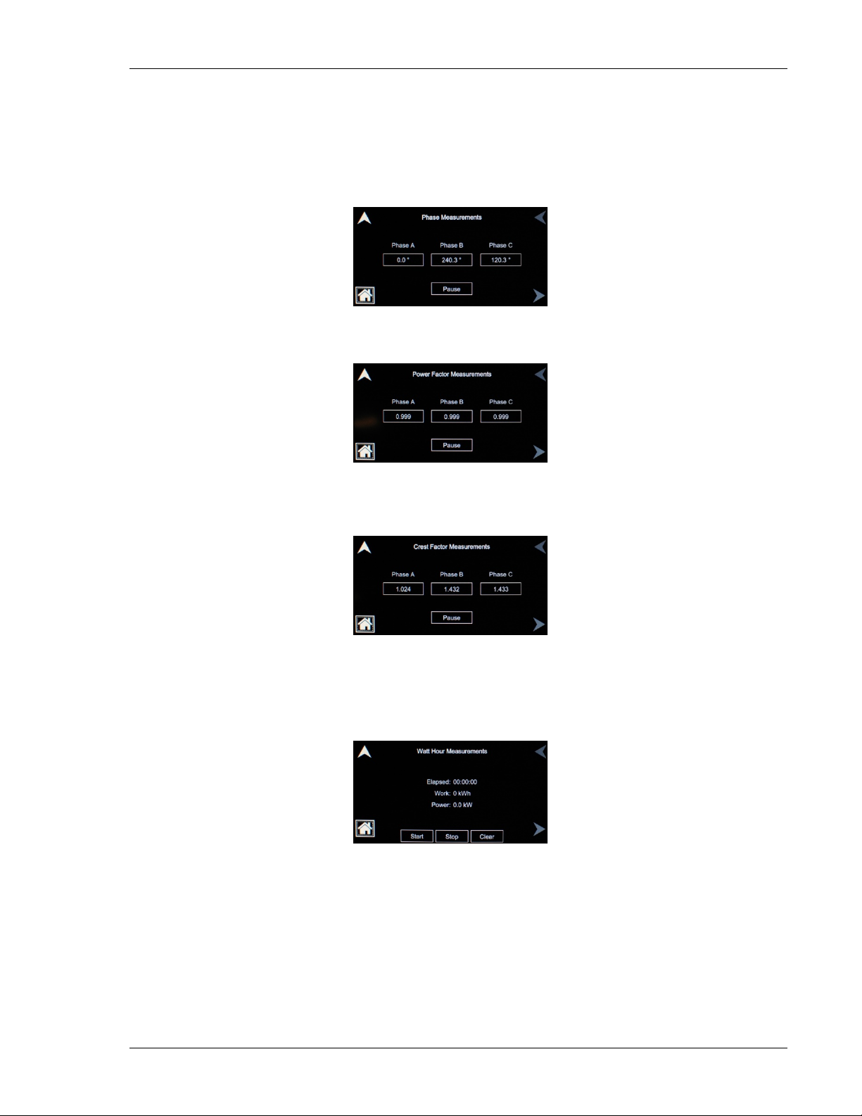
Asterion Series User Manual – 14U Models California Instruments
PHASE Displays the phase angle of the output of the power source: in a
standalone unit, the phase angle would be with respect to the
external SYNC signal; in an Auxiliary unit (wit h LKS option) of a
multi-phase group, the phase angle would be between the Auxiliary
output and the Master output. If the clock source is selected to be
internal, this parameter is not used.
POWER FACTOR Displays the power factor of the load.
CREST FACTOR Displays the crest factor of the output current as the ratio of its peak
value to its RMS value.
WATT HOUR Displays the energy, kWh, consumed by the load, and the true power
in kW. The Start and Stop function determine the interval during
which energy is calculated. The Clear function r esets t he
accumulated energy value.
M330511-01, REV-B 91
Page 92
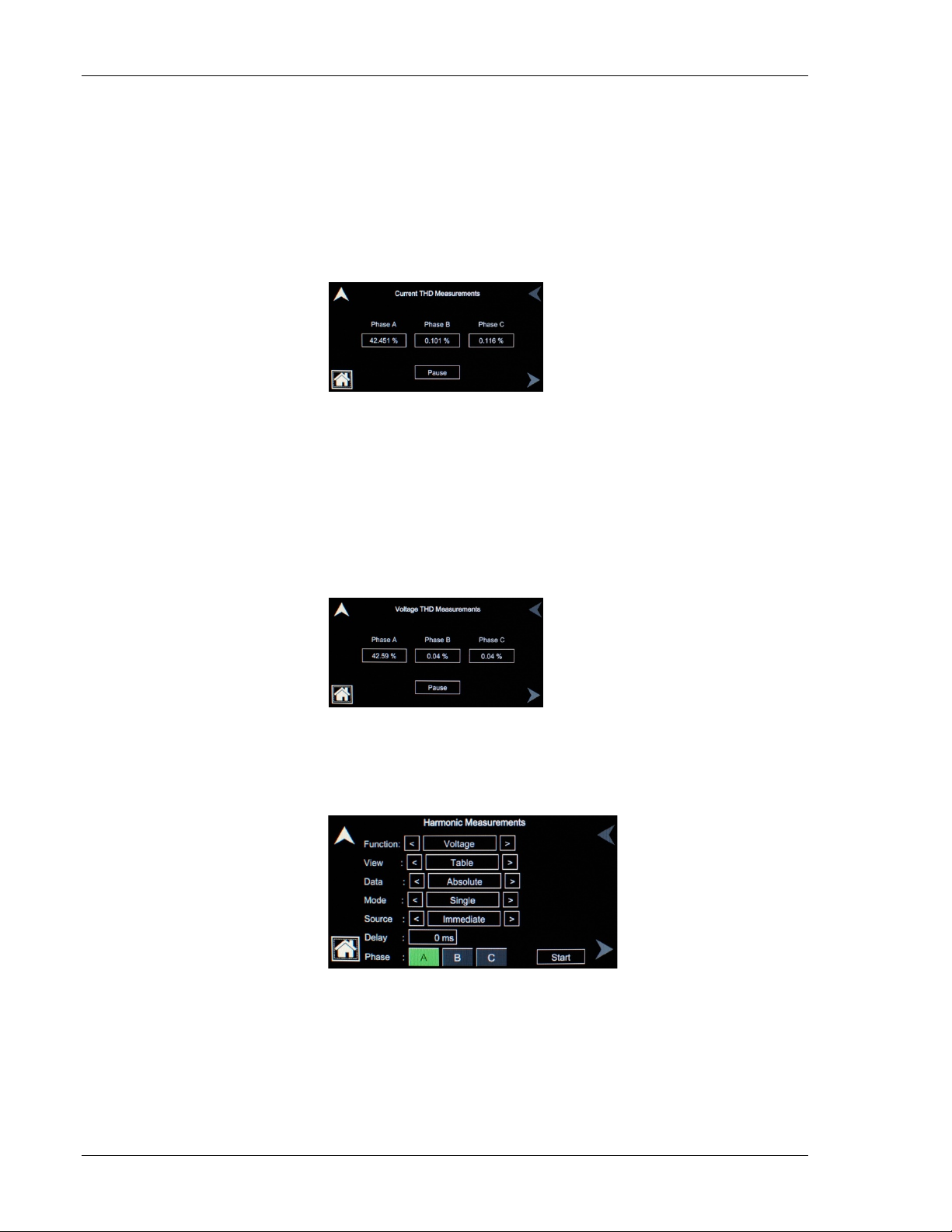
Asterion Series User Manual – 14U Models California Instruments
CURRENT THD Displays the total distortion of the output current. The distortion
calculation is based on the harmonics currents, H2 t hrough H50,
relative to the total RMS value of the current. Anot her common
definition of THD calculates the harmonics relative t o the value of the
fundamental current H1. There might be a difference in results
depending on the harmonic content. The method is selectabl e over
the digital interface with the SCPI command, MEAS:THD:MODE
<value>, with the value being either RMS (relativ e to total RMS) or
FUND (relative to fundamental).
VOLTAGE THD Displ ays the total distortion of the output voltage. The dist ort i on
calculation is based on the harmonics voltages, H 2 through H50,
relative to the total RMS value of the voltage. Another common
definition of THD calculates the harmonics relative t o the value of the
fundamental voltage H1. There might be a difference in results
depending on the harmonic content. The method is sel ectabl e over
the digital interface with the SCPI command, MEAS:THD:MODE
<value>, with the value being either RMS (relati ve to total RMS) or
FUND (relative to fundamental).
HARMONICS Displays harmonic content of voltage and current waveforms derived
from an FFT analysis. The amplitude and phase of ha rmonics up to
th
the 50
(bandwidth limited) are calculated and displayed.
Figure 4-18. HARMONICS Menu
92 M330511-01, REV-B
Page 93

Asterion Series User Manual – 14U Models California Instruments
The HARMONICS menu has the following fields:
Entry Description
FUNCTION HARMONICS menu: Selects Voltage or Current for display.
VIEW HARMONICS menu: Selects display modes, as follows:
Table: Displays the first 50 harmonics (bandwidth limited) in a
tabular text format, shown below;
Bar: Displays the first 50 harmonics (bandwidth limited) in a
graphical bar chart display, shown below.
DATA HARMONICS menu: Selects absolute or relative harmonics
display for TABLE and BAR view modes. In relative mode, all
harmonics are shown in a percentage of the fundamental which
is normalized at 100%. In absolute mode, the harmonic
amplitudes are shown in absolute volts or amperes.
MODE HARMONICS menu: Selects the trigger mode for the
acquisition, as follows:
SINGLE: Single-shot acquisition; in this mode, the acquisition is
triggered once each time the START field is selected. The
selected trigger source is used to determine t he trigger point.
Once the acquisition has been triggered, the data are displayed
and do not change until the next acquisition is triggered. This
mode is most appropriate for single-shot events, such as startup
currents.
CONTINUE: Continuous acquisition; in this mode, acquisitions
occur repeatedly and the data is updated on screen after each
trigger occurrence. This provides a continuou s update of the
data, and is most appropriate for repetitive signals.
SOURCE HARMONICS menu: Selects the event that will trigger a
measurement acquisition, as follows;
IMMEDIATE: Causes the acquisition to trigger immediately
when the START field is selected. This is an asynchronous
trigger event. The acquisition will always be trigge red in this
mode and data is available immediately.
PHASE: Causes the acquisition to trigger on the occurrence of
zero phase angle of the output voltage. When started, t he
acquisition holds until the zero phase angle occurs, before
triggering the acquisition. This mode allows exa ct positioning of
the acquisition data window with respect to the voltage
waveform.
DELAY HARMONICS menu: Selects the time delay to position the
trigger point relative to the acquisition window. A negative value
will provide pre-trigger information on data leading up to the
trigger event. The pre-trigger delay cannot exceed t he length of
the acquisition buffer; see Section
6.3.3 for details. A positive
trigger delay positions the data window after the trigger event.
Positive trigger delays can exceed the length of the acquisiti on
buffer in which case the trigger event itself will not be i n the
buffer anymore. The maximum value of the trigger delay is
1000 ms. The default trigger delay value is 0.0 ms which puts
the trigger event at the beginning of the acquisition window.
M330511-01, REV-B 93
Page 94

Asterion Series User Manual – 14U Models California Instruments
PHASE HARMONICS menu: Selects the output phase (Phase-A,
Phase-B, or Phase-C) for the harmonics measurement.
START HARMONICS menu: Starts a new acquisition run. When the
start field is selected, and after the trigger event occurs, the
display changes to the data display mode that was selected in
the VIEW field of the HARMONICS menu; refer to
Figure 4-18.
To return to the HARMONICS menu, tap the HOME button
while in the data display screen.
Harmonics Table View: This function displays the frequency spectrum of the output voltage
or current waveform (selected by Function selecti on-field) derived
through FFT (fast Fourier transform) analysis. The frequency
spectrum is listed in tabular format, ranging from the fundamental
th
through the 50
harmonic, in five groups of ten harmonics; refer to
Figure 4-19. The groups are selected through use of the Right and
Left arrow buttons. Each harmonic has the f ol lowing parameter data:
harmonic number, amplitude, and phase angle. Refer to
Section 6.2.2 for additional information on the harmonics tabular
view.
Figure 4-19. HARMONICS Menu, Table View
Harmonics Bar View: This function displays the frequency spectrum of the output voltage
or current waveform derived through FFT (fast Fourier transform)
analysis. The frequency spectrum is displayed in graphical format,
ranging from DC through the 49
th
harmonic, with up to 25 harmonic
components are shown per screen; refer to Figure 4-20. Individual
harmonics could be selected (shown with triangle al ong horizontal
axis) to display their parameter data using the Right a nd Left arrow
buttons, touch-screen, or encoder. The upper right -side presents the
data for the selected harmonic: harmonic numb er, frequency,
percentage of fundamental, and phase angle). Refer to Section 6.2.2
for additional information on the harmonics graphical view.
Figure 4-20. HARMONICS Menu, Bar Graph View
94 M330511-01, REV-B
Page 95

Asterion Series User Manual – 14U Models California Instruments
4.6.4 TRANSIENTS Screen Top-Level Menu
The Asterion Series power source provides the c apability of generating custom waveforms through
programming the output in a sequence of steps in a lis t of transients. The steps could be comprised of
combinations of changes in voltage, frequency, phase angle, waveform, and duration. The list could be
created, run and stored through either the front panel, or the remote digital interface using the Asterion
Virtual Panels GUI program or SCPI commands. A library of lists could be produced and stored in
memory of the power source for quick recall and utilization through use of SCPI commands (refer to the
Asterion Series Programming Manual P/N M330100-01 distributed on the CD, CIC496) or the Asterion
Virtual Panels GUI; refer to AMETEK PPD website, www.powerandtest.com
, to download latest version.
The TRANSIENTS Screen provides access to the transient list data. A t ransient list of up to 100 data
points is possible, represented by 100 transient st ep numbers from 0 through 99.
The top-level menu of the TRANSIENTS screen is shown in Figure 4-21. It can be reached in one of two
ways:
1. Tapping TRANSIENTS on Home Screen of the front panel touch-screen;
2. Scrolling to TRANSIENTS with the encoder and depressing the encoder switch.
The UP arrow button will return back to the previously select ed screen menu (in this case the
Home Screen). The HOME button will return back to the home screen that has the top-level menu for the
sub-menu being displayed; that is HOME Screen f o r the TRANSIENTS screen top-level menu.
Figure 4-21. TRANSIENTS Screen Top-Level Menu
The following menus are available in the TRANSIENTS top-level menu: SETTINGS, VIEW,
RUN.SETTINGS Menu
The SETTINGS menu allows selection of how parameter values are entered for time, voltage, and
frequency, trigger sources and characteristi cs, and how a list is executed; refer to Figure 4-22.
Figure 4-22. SETTINGS Menu
M330511-01, REV-B 95
Page 96

Asterion Series User Manual – 14U Models California Instruments
The SETTINGS menu has the following fields:
Entry Description
Phase Sets the output phase to which the programming of the transient s will
be applied.
Time Sets the units for time of the transient step; the default unit s are in
seconds. Alternately, the time could be changes to cycles of the
output frequency. Note that time durations in seconds may result in
rounding errors if the period of the programmed frequency is not an
integer number of milliseconds. For example, for 50 Hz output
(20 ms period), no rounding errors occur, but for 60Hz (16.66 ms
period) a rounding error would occur when converted. The t i m e
duration scale selection affects both the Time and End Delay
parameters.
Volt(age) Sets the units for voltage values; the default units are in V(RMS). V
is the RMS value of the output voltage, while % is the percent age of
the steady-state setting.
Freq(uency) Sets the units for frequency values; the default units are in Hz. Hz is
the value of the output frequency, while % is the percentage of the
steady-state setting.
Start Phase A Shows the start phase angle of the voltage transient in degr ees.
Only one start phase angle per transient sequence is allowed. The
start phase angle must be in the first transient event of the list. The
start phase angle is not valid for DC transients.
Step Defines how the step sequence of the transient list is executed; the
default is All:
All: All of the steps in the sequence are executed without brea ks;
Single: Each step is executed one at a time.
Trig(ger) The present state of the trigger settings is shown in the TRIG field.
Tap on the field to open the TRIGGER sub-menu to change settings;
refer to Figure 4-23.
96 M330511-01, REV-B
Page 97

Asterion Series User Manual – 14U Models California Instruments
Figure 4-23. SETTINGS Screen, TRIGGER Sub-Menu
The TRIGGER sub-menu has the following fields:
Entry Description
Phase Sync TRIGGER sub-menu: Determines when phase
synchronization is done; the default phase sync is All:
All: Synchronization is done at the beginning of the t ransient
list or pulse, for every count;
No(ne): Synchronization is done once at the beginning of the
transient list only for the first count.
Trig Out Source TRIGGER sub-menu: Selects the source for the trigger
List: At each point in the list (that has list-trigger enabled)
Start Source TRIGGER sub-menu: Determines the source of the trigger
Imm(ediate): Triggering occurs as soon as the SCPI
Bus: Triggering occurs following the SCPI comm and,
Ext(ernal): Triggering occurs when an external trigger input
output; the default source is BOT:
Bot: Beginning of transient output;
Eot: End of transient output;
when that step is reached.
event for the transient; the default source is IMM(ediate):
command, INITiate, is received;
INITiate, after receiving the SCPI command, *TRG, or the
IEEE-488 Group Execute Trigger (GET) signal from the
GPIB interface;
is received
M330511-01, REV-B 97
Page 98

Asterion Series User Manual – 14U Models California Instruments
4.6.4.1 VIEW Menu
The VIEW menu shows the transient list, with sequence numbe rs which are stored in the transient list
buffer. Figure 4-24 shows the menu when the buffer is empty, while Figure 4-25 shows the menu when
entries are present.
Figure 4-24. VIEW Menu, With Empty Buffer
Figure 4-25. VIEW Menu, With Transient List Entry
The VIEW menu has the following fields:
Entry Description
Add Allows generating a new transient list.
Before Inserts a step before the selected transient step
Edit Opens the selected st ep for editing parameters.
After Inserts a step after t he selected transient step
Del Permanently deletes the selected transient step
Delete All Clears the transient list buffer
98 M330511-01, REV-B
Page 99

Asterion Series User Manual – 14U Models California Instruments
4.6.4.2 ADD Sub-Menu
The ADD sub-menu is opened when the ADD function is selected on the VIEW screen; refer to Figure
4-26. It allows selection of the type of transient to be added to the sequence.
Figure 4-26. VIEW Menu, ADD Sub-Menu
The ADD sub-menu has the following fields:
Entry Description
DROP Causes the output voltage to go to zero volts for a specified period of
time. As with the step transient, the voltage change is instantaneous.
At the end of the drop, the voltage will return to the a m pl i t ude at t he
beginning of the step.
VOLTAGE SWEEP/STEP VOLTAGE SWEEP causes the output voltage to change from the
present value to a specified end value at a specified rat e of change,
while a VOLTAGE STEP causes an instantaneous change in output
voltage. The new value will be held for the specified time duration.
The final output voltage value of a sweep and a step transient step
should be different than the value at the start of the transient step, or
no change in output voltage will occur.
M330511-01, REV-B 99
Page 100

Asterion Series User Manual – 14U Models California Instruments
VOLTAGE SURGE/SAG VOLTAGE SURGE and SAG are temporary changes in
amplitude. The output voltage will change from its present value
to a specified value for a specified duration. Surge is a change t o
a higher value, while sag is a change to a lower value. After the
time duration has expired, the output voltage returns t o a specified
end value. This value could be the same or different from the
value present prior to the start of the surge or sag.
FREQUENCY SWEEP/STEP FREQUENCY SWEEP causes the output frequency to change
from the present value to a specified end value at a specif ied rate
of change, while a FREQUENCY STEP is an instantaneous
change in output frequency. The new value will be hel d for the
specified time duration. The final output frequency value of a
sweep and a step transient step should be different than the value
at the start of the transient step, or no change in output frequency
will occur.
FREQUENCY SURGE/SAG FREQUENCY SURGE and SAG are temporary changes in
frequency. The output frequency will change from i ts present
value to a specified value for a specified duration. Surge is a
change to a higher value, while sag is a change to a lower value.
After the time duration has expired, the output frequency retur ns
to a specified end value. This value could be the same or
different from the value present prior to the start of the surge or
sag.
100 M330511-01, REV-B
 Loading...