

Page 1

Reference manual
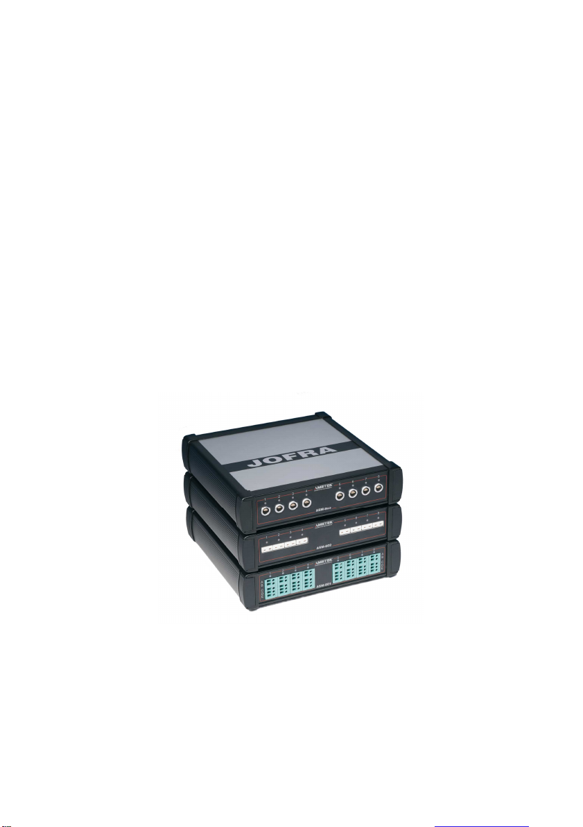
Advanced Signal Multi-Scanner
Jofra ASM-801/802/803 A/B
Page 2
Reference Manual
Advanced Signal Multi-scanner
JOFRA ASM-801/802/803 A/B
Copyright 2009 AMETEK Denmark A/S
Page 3
About this manual….
attention.
• The structure of the manual
This reference manual is aimed at users who are familiar with
AMETEK multi-scanners, as well as those who are not. The
manual is divided into 11 chapters, which describe how to set
up, operate, service and maintain the Multi-scanner. The
technical specifications are described and accessories may be
ordered from the list of accessories.
• Safety symbols
This manual contains a number of safety symbols designed to
draw your attention to instructions, which must be followed
when using the instrument, as well as any risks involved.
Warning
Conditions and actions which may compromise
the safe use of the instrument and result in
considerable personal injury or material damage.
Caution…
Conditions and actions which may compromise
the safe use of the instrument and result in slight
personal or material damage.
Note…
Special situations, which demand the user’s
2 2017-08-11 125614 04
Page 4

List of contents
1.0 Introduction ............................................................................ 5
2.0 Safety instructions ................................................................. 7
3.0 Receiving the multi-scanner .................................................. 9
3.1 Multi-scanner models .................................................................. 11
3.1.1 A Model version .............................................................. 12
3.1.2 B Model version .............................................................. 14
4.0 Setting up the multi-scanner ............................................... 15
4.1 Preparing the multi-scanner ........................................................ 16
4.2 Connecting sensors to the multi-scanner ................................... 17
4.2.1 Connecting RTDs ........................................................... 18
4.2.2 Connecting Thermocouples and Voltages Sources ....... 18
4.2.3 Connecting 4-20mA Transmitters .................................. 20
4.3 Cascading the multi-scanner ...................................................... 21
4.4 Connecting A-models to other instruments ................................ 22
5.0 Operating the multi-scanner ................................................ 23
5.1 Manual operation ........................................................................ 23
5.2 Operation with JOFRACAL ......................................................... 24
6.0 Remote operation ................................................................. 25
6.1 Setting up the RS-232 Port for Remote Control ........................ 25
6.2 Units ............................................................................................ 26
6.2.1 Temperature units .......................................................... 26
6.2.2 Electrical units ................................................................ 26
6.3 Commands .................................................................................. 26
6.3.1 *CLS ............................................................................... 26
6.3.2 *ESE <reg val> ............................................................... 26
6.3.3 *ESE? ............................................................................. 27
6.3.4 *ESR? ............................................................................. 27
6.3.5 *IDN? .............................................................................. 27
6.3.6 *OPC .............................................................................. 27
6.3.7 *OPC? ............................................................................ 28
6.3.8 *RST ............................................................................... 28
6.3.9 *SRE <reg val> ............................................................... 28
6.3.10 *SRE? ............................................................................ 28
6.3.11 *STB? ............................................................................. 28
6.3.12 *TST? ............................................................................. 28
6.3.13 *WAI ............................................................................... 29
6.3.14 SYSTEM_IDN? .............................................................. 29
125614 04 2017-08-11 3
Page 5

6.3.15 SYS_CONF .................................................................... 29
6.3.16 SYS_CONF? .................................................................. 29
6.3.17 TEMP_UNIT ................................................................... 30
6.3.18 TEMP_UNIT? ................................................................. 30
6.3.19 CH_CONF ...................................................................... 30
6.3.20 CH_CONF? (@<channel>) ............................................ 32
6.3.21 VAL? (@<ch_list >) ........................................................ 33
6.3.22 CH_SCAN (@<ch_list>) ................................................ 33
6.3.23 CH_SCAN_STOP .......................................................... 33
6.3.24 CH_SCAN? .................................................................... 33
6.3.25 CAL_DATE..................................................................... 33
7.0 Maintenance ......................................................................... 34
7.1 Storing ......................................................................................... 34
7.2 Cleaning ...................................................................................... 34
7.3 Returning the multi-scanner to service ....................................... 34
8.0 Errors .................................................................................... 37
9.0 Adjusting the multi-scanner ................................................ 39
9.1 Adjusting and calibrating the instrument ..................................... 39
9.2 Introduction to AMETRIM Software .......................................... 39
9.2.1 Installing the AMETRIM Software .................................. 40
9.2.2 Connecting the PC and the ASM-80x ............................ 40
9.2.3 Starting the AMETRIM Software .................................... 40
9.2.4 Run calibration/adjustment ............................................. 42
9.2.5 To calibrate the ASM-80x ............................................... 45
9.2.6 To adjust and calibrate (as left) the ASM-80x ................ 46
9.2.7 To calibrate (as found), adjust and calibrate (as left) the
ASM-80x ......................................................................... 48
9.2.8 Setup Printer................................................................... 49
10.0 Technical specifications ..................................................... 50
11.0 List of accessories ............................................................... 60
4 2017-08-11 125614 04
Page 6

AMETEK Denmark A/S was ISO
1.0 Introduction
Congratulations on your new AMETEK JOFRA
Advanced Signal Multi-scanner!
With the AMETEK JOFRA Multi-scanner, you have chosen an
extremely effective instrument, which we hope will perform according
to your expectations. During the past several years, we have acquired
extensive knowledge of industrial temperature calibration. This
expertise is reflected in our products, which are all designed for daily
use in an industrial environment. Please note that we would be very
interested in hearing from you if you have any ideas or suggestions
for changes to our products.
This reference manual applies to the following instruments:
• JOFRA ASM-801 A
• JOFRA ASM-801 B
• JOFRA ASM-802 A
• JOFRA ASM-802 B
• JOFRA ASM-803 A
• JOFRA ASM-803 B
ISO-9001 certified
by Bureau Veritas Certification Denmark.
125614 04 2017-08-11 5
-9001 certified in September 1994
Page 7

CE-label
Your new multi-scanner bears the CE label and
conforms to the Electromagnetic Compatibility (EMC)
Directive 2014/30/EU and RoHS Recast (RoHS II)
Directive 2011/65/EU*.
Technical assistance
Please contact the dealer from whom you acquired the instrument if
you require technical assistance.
1.1 Warranty
This instrument is warranted against defects in workmanship, material
and design for two (2) years from date of delivery to the extent that
AMETEK will, at its sole option, repair or replace the instrument or
any part thereof which is defective, provided, however, that this
warranty shall not apply to instruments subjected to tampering or,
abuse, or exposed to highly corrosive conditions.
THIS WARRANTY IS IN LIEU OF ALL OTHER WARRANTIES
WHETHER EXPRESS OR IMPLIED AND AMETEK HEREBY
DISCLAIMS ALL OTHER WARRANTIES, INCLUDING, WITHOUT
LIMITATION, ANY WARRANTY OF FITNESS FOR A PARTICULAR
PURPOSE OR MERCHANTABILITY. AMETEK SHALL NOT BE
LIABLE FOR ANY INCIDENTAL OR CONSEQUENTIAL DAMAGES,
INCLUDING, BUT NOT LIMITED TO, ANY ANTICIPATED OR LOST
PROFITS.
This warranty is voidable if the purchaser fails to follow any and all
instructions, warnings or cautions in the instrument’s User Manual.
If a manufacturing defect is found, AMETEK will replace or repair the
instrument or replace any defective part thereof without charge;
however, AMETEK’s obligation hereunder does not include the cost
of transportation, which must be borne by the customer. AMETEK
assumes no responsibility for damage in transit, and any claims for
such damage should be presented to the carrier by the purchaser.
* ASM-801 A / ASM-801 B / ASM-802 A / ASM-802 B / ASM-803 A / ASM-803 B from serial no. xxxxxx-00478
6 2017-08-11 125614 04
Page 8
2.0 Safety instructions
and/or damage to the instrument.
specifications for supported ranges.
Read this manual carefully before using
the instrument!
Please follow the instructions and procedures described in
this manual. They are aimed at allowing you to make the
best of your multi-scanner and avoid any personal injuries
Disposal – WEEE Directive
The multi-scanner contains Electrical and Electronic
circuits and must be properly recycled or disposed of (in
accordance with the WEEE Directive 2012/19/EU).
Warning
The multi-scanner has been designed to calibrate and
measure low voltage signals. To ensure the safety of the
operator and the instrument, DO NOT connect the multi-
scanner to input voltages above 30 Volts.
To avoid possible electric shock or personal injury:
• The multi-scanner must not be used for any purposes
other than those described in this manual, as it might
cause a hazard.
• The multi-scanner has been designed for indoor use
only and is not to be used in wet locations.
• Do not operate the multi-scanner in environments of
explosive gas, vapour, or dust.
• The multi-scanner is not designed for operation in
altitudes above 2000 meters.
• Only use the specified mains adaptor approved for the
voltage and plug configuration in your area.
• Do not apply more than the rated voltage. See
125614 04 2017-08-11 7
Page 9

• Select the proper function and range for your
described in this manual or uses unauthorized spare par
ts.
measurement.
• Always position the multi-scanner to enable easy and
quick disconnection of the power source (mains
adaptor).
• Do not use the multi-scanner if it operates abnormally.
Protection may be impaired. When in doubt, get the
multi-scanner serviced.
• Disconnect test leads before changing to another
measure or source function.
• During set-up, make sure that there is correlation
between the software set-up, and the actual distribution
of the sensors connected to the multi-scanner. The
software cannot detect misplacements of sensors.
• When servicing the multi-scanner, only use specified
replacement parts. There are no user serviceable parts
inside the multi-scanner.
Caution…
8 2017-08-11 125614 04
To avoid possible damage to the multi-scanner or to
the equipment under test:
• Disconnect the power and discharge all high-voltage
capacitors before testing resistance or continuity.
• Use the proper connectors, function and range for your
measurement.
• When using the switch test function, make sure that no
other equipment, such as heavy loads or sources, is
connected in the test loop.
Note…
The product liability only applies if the instrument is
subject to a manufacturing defect. This liability becomes
void if the user fails to follow the maintenance instructions
Page 10
3.0 Receiving the multi-scanner
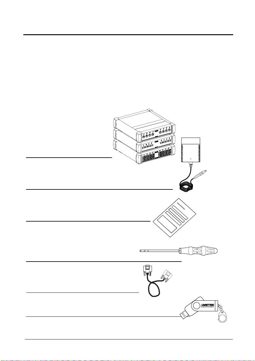
software package “JO
FRACAL”
When you receive the instrument…
• Unpack and check the multi-scanner and the accessories
carefully.
• Check the parts according to the list shown below.
If any of the parts are missing or damaged, please contact the
dealer who sold you the multi-scanner.
You should receive:
• 1 multi-scanner
• 1 power supply
• 1 traceable certificate
• 1 screw driver (ASM-801 only)
• 1 RS 232 serial cable
• 1 USB key containing reference manual and
125614 04 2017-08-11 9
Page 11

When reordering, please specify the part numbers according
to the list of accessories, section. 11.0
10 2017-08-11 125614 04
Page 12
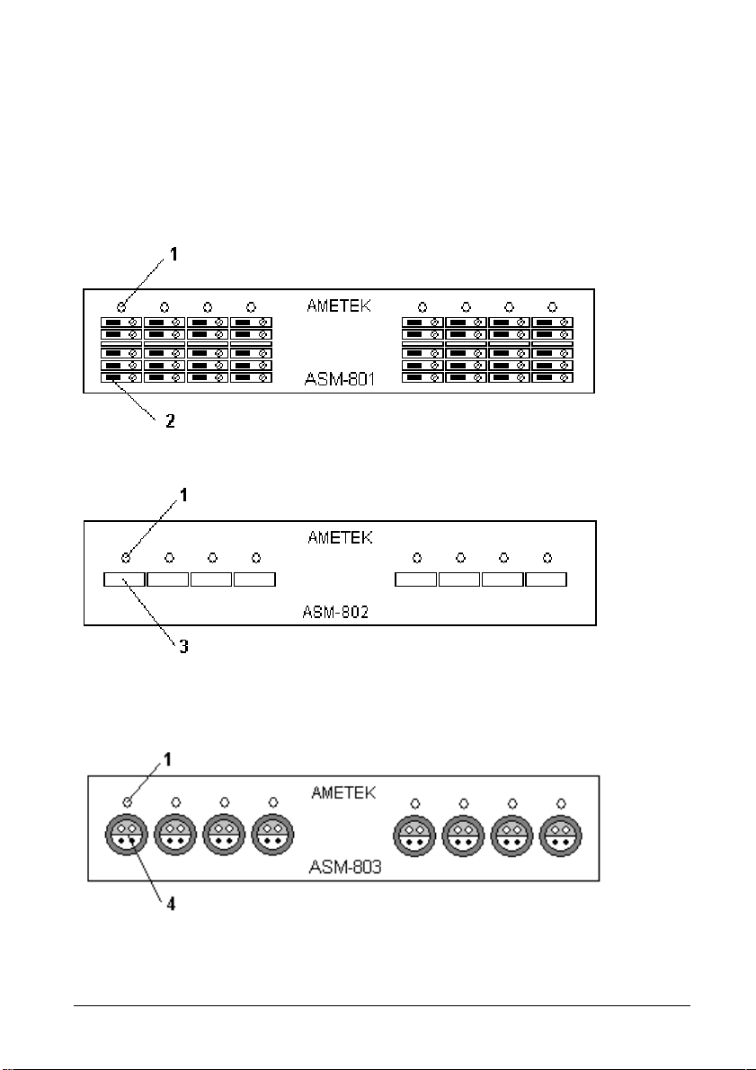
3.1 Multi-scanner models
The Advanced Signal Multi-scanner is available in 3 different models;
801, 802 and 803 in two different model versions – A and B.
Model ASM-801 with Multi input
Model ASM-802 with Mini-Thermocouple input
Model ASM-803 with LEMO input
125614 04 2017-08-11 11
Page 13
Pos. Description
for operation.
SMP
-U-F
1 LED indicating which channel is being read. LED channel 1
will flash once a second when the Multi-scanner is ready
2 Screw connection, max. wire size 2,5mm2.
3 Miniature thermocouple connector from OMEGA, type
4 Connector from LEMO, type ERA.1S.304.CLL
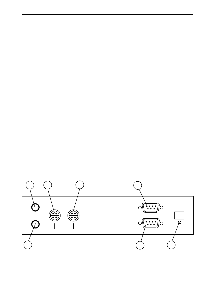
3.1.1 A Model version
The A version operates by connecting selected channels to a single
output channel. In order to collect measurements a measuring device
is connected to the output channel.
Apart from being controlled from a connected computer, the A version
can also be operated manually.
Depending on the type of measuring device connected to the
instrument, there is a certain settling time between channel shifts.
a
c
d
e
CHANNEL SELECT
UP
DOWN
ANALOG BUS
IN OUT
SLAVE
PC / MASTER
30V DC 0.5A
_
+
b
f
g
12 2017-08-11 125614 04
Page 14

Holding down a and b will reset the instrument
.
be connected here. For applications, see section 4.3.
the instrument in front to the PC/MASTER.
comply
with the requirements in EN61326 (
2013
).
Pos. Description
a Manual channel select; UP.
b Manual channel select; DOWN
c ANALOG BUS IN. If multiple multi-scanners are connected
in series, the analogue line out of the next instrument must
d ANALOG BUS OUT. Connect the measuring device here
or if multiple multi-scanners are connected in series,
connect the instrument in front to the ANALOG BUS OUT.
e SLAVE. If multiple multi-scanners are connected in series,
the RS232 master line of the succeeding instrument must
be connected here. For applications, see section 4.3.
f PC/Master. Connect the controlling computer here, or if
multiple multi-scanners are connected in series, connect
g 30V DC 0.5A. Power supply connection.
Use only mains adapter supplied by AMETEK in order to
125614 04 2017-08-11 13
Page 15
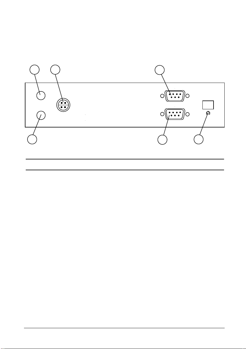
3.1.2 B Model version
be connected here. For applications
, see section 4.3.
be connected here. For applications, see section 4.3.
the instrument in front to the PC/MASTER.
a
The B version has the same functions as the A version, but it differs
as it is not necessary to include a measuring instrument to the set-up,
as the multi-scanner has built-in measuring capabilities.
c
e
ANALOG BUS
IN
SLAVE
PC / MASTER
30V DC 0.5A
_
+
b
f
g
Pos. Description
a + b Holding down a and b will reset the instrument.
c ANALOG BUS IN. If multiple multi-scanners are connected
in series, the analogue line out of the next instrument must
e SLAVE. If multiple multi-scanners are connected in series,
the RS232 master line of the succeeding instrument must
f PC/Master. Connect the controlling computer here or if
multiple multi-scanners are connected in series, connect
g 30V DC 0.5A. Power supply connection.
Use only mains adapter supplied by AMETEK in order to
comply with the requirements in EN61326 (2013).
14 2017-08-11 125614 04
Page 16
4.0 Setting up the multi-scanner
Warning
• The multi-scanner must not be used for any purposes
other than those described in this manual, as it might
cause a hazard.
• Do not connect the multi-scanner to input voltages
above 30 Volts.
• Only use the specified mains adaptor approved for the
voltage and plug configuration in your area.
• Do not operate the multi-scanner in environments of
explosive gas, vapour, or dust.
• The multi-scanner has been designed for indoor use
only and is not to be used in wet locations.
• The multi-scanner is not designed for operation in
altitudes above 2000 meters.
• Do not apply more than the rated voltage/current. See
specifications for supported ranges.
• Select the proper function and range for your
measurement.
Caution…
In case of resistive measurements, it is very important that
125614 04 2017-08-11 15
no capacities are present in the circuit loop. If present, they
must be discharged, before wires are connected to the
instrument.
When commencing the switch test, which is in fact a
resistive measurement, the thermostats must not be
connected to any other voltage source.
Page 17

4.1 Preparing the multi-scanner
fluctuations e.g. draught or sunlight.
measuremen
ts or even possible damage to the sensors.
Connect RS232 cables and analog signal cables before the
DC power is applied.
Place the multi-scanner on an even stable surface where you intend
to use it. Make sure that the scanner is not subjected to temperature
Caution…
The multi-scanner can be set up to supply transmitters with
24V max. 27mA.
When changing the set-up from one type of sensor to
another, especially when changing from transmitters to
other types of sensors, make sure that the multi-scanner is
reset.
The order in which the sensors are connected to the multiscanner makes no difference. When setting up the
instrument, via the control software, it is possible to choose
individually which channels to use. But what matters is
that there is consistency between where to connect the
sensor to the instrument and what to write in the controlling
software. Inconsistency would result in faulty
LED channel 1 flashes once every second when the multi-scanner is
ready.
A constantly lit LED indicates which channel is currently being read.
Notice that the shifting of the internal relays can be heard when
setting up the multi-scanner and between channel shifts. This is not
an error.
16 2017-08-11 125614 04
Page 18
4.2 Connecting sensors to the multi-scanner
A
E
Warning
Disconnect test leads before changing to another measure
or source function.
Caution…
For correct connection of sensors to the multi-scanner use the
diagrams below.
To avoid possible damage to the multi-scanner or to
the equipment under test:
• Disconnect the power and discharge all high-voltage
capacitors before testing resistance or continuity.
• Use the proper connectors, function and range for your
measurement.
• When using the switch test function, make sure that no
other equipment, such as heavy loads or sources, is
connected in the test loop.
A
B
C
D
E
B
C
B
C
D
125614 04 2017-08-11 17
Page 19
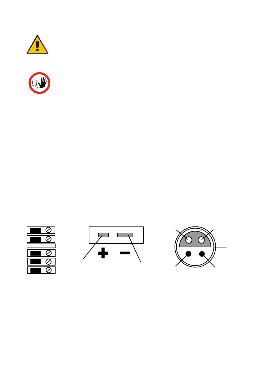
4.2.1 Connecting RTDs
3-wire
4-wire
A B -
2-wire
C D -
See section 10.0; Technical specifications for supported types of
RTDs. The calibrator accepts 2-, 3-, and 4-wire inputs, with the 4-wire
input being the most accurate.
4.2.2 Connecting Thermocouples and Voltages Sources
See section 10.0; Technical specifications for supported types of
thermocouples. The multi-scanner has a cold junction compensation
function. Normally this function should be ON and the actual
temperature of the thermocouple can be measured.
With CJC OFF, the multi-scanner will measure the difference
between the thermocouple at the junction and at its TC input terminal.
18 2017-08-11 125614 04
Page 20

Note…
The multi-scanner is also able to measure the mV of a thermocouple,
which can be used along with a table if the corresponding TC type is
not supported by the multi-scanner.
For best accuracy wait, as a minimum, 5 minutes after
connecting the sensors, before any measurements are
taken. Do not apply heat to the plugs while measuring the
TC e.g. by touching them.
125614 04 2017-08-11 19
Page 21

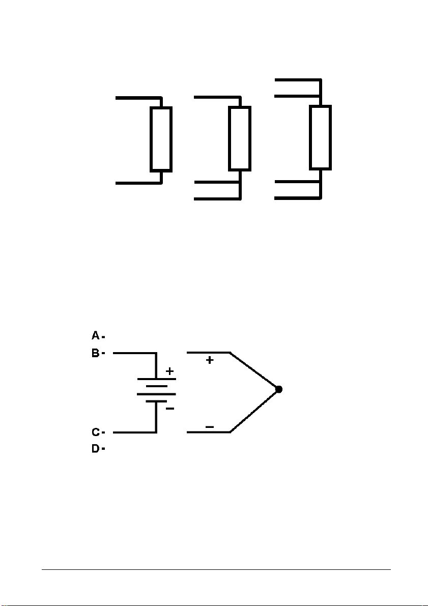
4.2.3 Connecting 4-20mA Transmitters
E -
Connection a Connection b
Measuring current with loop power
In order to test a 2-wire loop powered transmitter, which is
disconnected from wiring, use the loop power function. This function
activates a 24V supply, in series with the current measuring.
Connect as shown on figure “Connection a”.
Measuring current without loop power
Transmitters with built-in supply or transmitters using external supply
are connected as shown on figure “Connection b”.
Measuring ground
20 2017-08-11 125614 04
Page 22

4.3 Cascading the multi-scanner
It is possible to connect up to 3 multi-scanners in series and build a
system, which enables you to measure up to 24 sensors
simultaneously.
The first multi-scanner to be placed after the PC can be either an Aor a B-model. Succeeding multi-scanners have to be A-models. It is
not possible to connect multiple B-models in series.
When the DC power has been connected to the multi-scanners and
the proper RS232 connection has been established between all the
instruments, the LED’s on channel 1 on all instruments involved will
flash simultaneously.
First model is a B-model, succeeding multi-scanners are Amodels
First model is an A-model, succeeding multi-scanners are Amodels
125614 04 2017-08-11 21
Page 23

4.4 Connecting A-models to other instruments
A
E
The output from the ASM A-model is a LEMO ERA.1S.304.CLL
connector. For correct connection to other instruments, use the
diagram below.
For connecting A-models to other instruments, different cables can be
supplied.
Part no. 125534 Cable with male LEMO/LEMO connector can be
used to connect an ASM A-model to e.g. a JOFRA DTI-1000 or
JOFRA AMC-900.
Part no. 125587 Cable with mini compensation/LEMO connector can
be used to connect an ASM A-model to e.g. a JOFRA ASC300,
JOFRA AMC-900 JOFRA ATC-B models or other instruments with
mini compensation thermocouple connectors.
Part no. 122823 Cable with banana/LEMO connector can be used to
connect an ASM A-model to e.g. a JOFRA ASC300, JOFRA AMC900, JOFRA ATC-B models or other instruments with a safety 4 mm
banana sockets. For correct connection, use the diagram below.
For connecting A-models to other ASM's, use 125618, cable kit.
B
C
Brown
White
Yellow
Green
Red
Red
Black
Black
D
Green
A
B
C
D
E
22 2017-08-11 125614 04
Page 24

5.0 Operating the multi-scanner
Push buttons for manual channel shift
5.1 Manual operation
A-models
The push buttons on the back of the A-models can be used for
manual channel shift. When LED 1 is flashing no channel is selected.
These buttons will enable the user to operate the instrument without
using a connected computer.
Supplying transmitters is not possible during manual operation.
Press both push buttons for two seconds and the multi-scanner will
reset itself.
Warning
• Do not use the multi-scanner if it operates abnormally.
Protection may be impaired. When in doubt, get the
multi-scanner serviced.
• When servicing the multi-scanner, only use specified
replacement parts. There are no user serviceable parts
inside the multi-scanner.
CHANNEL SELECT
UP
DOWN
ANALOG BUS
IN OUT
125614 04 2017-08-11 23
Page 25

Push buttons for resetting
B-models
the instrument
ANALOG BUS
IN
The push buttons on the back of the B-models can only be used to
reset the instrument.
Press both push buttons down for two seconds and the multi-scanner
will reset itself.
5.2 Operation with JOFRACAL
Both A- and B-models are operated by means of the sensor test and
calibration software, AMETEK Denmark A/S JOFRACAL. The
program is included on the enclosed CD.
For introduction and use of the program, the user is advised to read
the user manual included on the CD. All possibilities and limits of the
program are described in the manual.
24 2017-08-11 125614 04
Page 26

6.0 Remote operation
The ASM can be remotely controlled using a PC terminal, or by a
computer program running the calibrator in an automated system. It
uses an RS-232 serial port connection for remote operation. With this
connection the user can write programs on the PC, with Windows
languages like Visual Basic to operate the calibrator, or use a
Windows terminal, such as Hyper Terminal, to enter single
commands.
6.1 Setting up the RS-232 Port for Remote
Control
Note: The RS-232 connection cable should not exceed 15m unless
the load capacitance measured at connection points is less than
2500pF.
Serial parameter values:
115200 baud
8 data bits
1 stop bit
no parity
Xon/Xoff
EOL (End of Line) character or CR (Carriage Return) or
both
To set up remote operation of the calibrator on the Windows Hyper
Terminal, connected to a COM port on the PC, use the following
procedure:
1. Start Hyper Terminal (located in Accessories/
Communications of the Windows Start menu)
2. Select New Connection.
3. For Name enter ASM-80x. Select the serial port that the unit
is connected to.
4. Enter the above information for port settings.
125614 04 2017-08-11 25
Page 27

5. Select ASCII setup from File/Properties/Settings and mark
these choices:
Echo typed characters locally
Wrap lines that exceed terminal width
6. Select Ok
7. To see if the port works enter *IDN?. This command will
return information on the unit.
6.2 Units
6.2.1 Temperature units
CEL = °C
KEL = K
FAR = °F
6.2.2 Electrical units
V = volts
OHMS = ohms
A = amps
Hz = Hertz
MV = 10-3V
KOHMS = 103OHMS
6.3 Commands
6.3.1 *CLS
SCPI standard command (Clear Status).
Clears the ESE, ESR, SRE and STB registers, i.e. set them to 0.
6.3.2 *ESE <reg val>
SCPI standard command (standard Event Status Enable).
26 2017-08-11 125614 04
Page 28

Set the Event Status Enable register, which is a 8-bit register, i.e. a
value between 0 and 255 must be specified as argument
6.3.3 *ESE?
SCPI standard command (standard Event Status Enable query).
Outputs the value of the Event Status Enable register.
6.3.4 *ESR?
SCPI standard command (standard Event Status Register query).
Outputs the value of the Event Status Register.
This implementation supports the following bits in the ESR register (if
enabled with the ESE register):
• Power ON (PON, bit 7): This bit is set to 1 after power up.
• Command Error (CME, bit 5): This bit is set when an unknown
command has been received or a known command with
wrong arguments has been received.
• EXE (bit 4): This bit is set when an error during the execution
of a command has occurred.
• Operation Complete (OPC, bit 0): Is set whenever a command
has been executed.
The events in the ESR register are cleared after a read.
6.3.5 *IDN?
SCPI standard command (Identification query). Return information for
the unit in the format <manufacture>,<model>,<serial#>,<version>,
e.g.:
AMETEK,ASM801A,123456-12345, 1.00
6.3.6 *OPC
SCPI standard command (Operation Complete).
Because the system only implements sequential commands this
command will immediately set the OPC bit in the Event Status
Register when the command is executed.
125614 04 2017-08-11 27
Page 29

6.3.7 *OPC?
SCPI standard command (Operation Complete query).
Because the system only implements sequential commands this
command will immediately output a “1” when the command is
executed.
6.3.8 *RST
SCPI standard command (Reset). In this implementation the
execution of this commands correspond to a power off/on.
6.3.9 *SRE <reg val>
SCPI standard command (Service Request Enable).
Set the Service Request Enable register, which is a 8-bit register, i.e.
a value between 0 and 255 must be specified as argument.
6.3.10 *SRE?
SCPI standard command (Service Request Enable query).
Outputs the value of the Service Request Enable register.
6.3.11 *STB?
SCPI standard command (Status Byte query).
Outputs the value of the Status Byte register. In this implementation
only the ESB bit (Event Summary Bit) is used, i.e. the MAV bit
(Message Available) and RQS/MSS bit is always set to 0.
The ESB bit is set if one of the enabled events in the ESR register
has occurred since last read of the STB register. The ESB bit is
always cleared after a read.
6.3.12 *TST?
SCPI standard command (Self-Test). In this implementation no selftest is performed when executing this command, i.e. this command
always return OK.
28 2017-08-11 125614 04
Page 30

6.3.13 *WAI
SCPI standard command (Wait-to-continue).
Because the system only implements sequential commands this
command has no functionality.
6.3.14 SYSTEM_IDN?
Returns IDN-information for all ASM-units connected in a format like
the *IDN-command. However, it is extended with the box number (fist
field) and calibration date (last field), e.g.:
1,AMETEK,ASM801B,123456-11111,0.01,2005-06-28
2,AMETEK,ASM802A,123456-22222,0.01,2005-06-28
3,AMETEK,ASM803A,123456-33333,0.01,2005-06-28
6.3.15 SYS_CONF
SYS_CONF <Freq.> Hz,<Speed>
<Freq> = 50, 60
<Speed> = 1,2,3,4
Sets up A/D converter speed/filters in all connected units. The speed
parameter is only used by B-models. However, the speed parameter
must always be specified.
Default settings at power up is 50 Hz and speed 1.
6.3.16 SYS_CONF?
Returns the actual SYS_CONF configuration.
Example 50 Hz, 3
If the connected units have different configurations “ERROR” will be
returned.
125614 04 2017-08-11 29
Page 31

6.3.17 TEMP_UNIT
TEMP_UNIT <temp. unit>
<temp. unit> = CEL, FAR, KEL
Sets temperature unit in all connected units. Default setting at power
up is CEL.
6.3.18 TEMP_UNIT?
Returns temperature unit: <temp. unit> = CEL, FAR, KEL
If the connected units have different configurations “ERROR” will be
returned.
6.3.19 CH_CONF
Configures the channels.
CH_CONF DCV (@<ch_list>)
Sets the selected for measuring voltage.
Example: CH_CONF DCV (@2)
CH_CONF DCV, <Range low> V, <Range high> V, <Temperature
low> <temp. unit>, <Temperature high> <temp. unit>
(@<ch_list>)
Sets the selected for measuring voltage transmitter (T/V)
<Range low> = V_LOW_XX = 0.000 [V] (default value)
<Range high> = V_HIGH_XX = 10.000 [V] (default value)
<Temperature low> = V_TEMP_LOW_XX = 0 [°C] (default value)
<Temperature high> = V_TEMP_HIGH_XX = 100 [°C] (default value)
CH_CONF MA (@<ch_list>)
Sets the selected channels for measuring current
CH_CONF MA, <Range low> A, <Range high> A, <Temperature
low> <temp. unit> , <Temperature high> <temp. unit>
(@<ch_list>)
Sets the selected channels for measuring current transmitter (T/I)
30 2017-08-11 125614 04
Page 32

<Range low> = MA_LOW_XX = 0.004 [A] (default value)
<Range high> = MA_HIGH_XX = 0.020 [A] (default value)
<Temperature low> = MA_TEMP_LOW_XX = 0 [°C] (default value)
<Temperature high> = MA_TEMP_HIGH_XX = 100 [°C] (default
value)
CH_CONF MV (@<ch_list>)
Sets the selected for measuring mV.
CH_CONF <TC type>, <CJC type>, <Manuel CJC temperature>
<temp. unit>, <A>, <B>, <C> (@<ch_list>)
Sets the selected channels for measuring thermocouple
<TC type> can be : J, K, T, E, R, S, B, XK, BP, L, U, N,
CUSTOM J,
CUSTOM K,
CUSTOM T,
CUSTOM E,
CUSTOM R,
CUSTOM S,
CUSTOM B,
CUSTOM XK,
CUSTOM BP,
CUSTOM L,
CUSTOM U,
CUSTOM N
<CJC type> can be : INT, EXT, MAN
<Manuel CJC temperature> is only used with <CJC type> = MAN
<A>, <B>, <C> is only used for CUSTOM types for calculating a
compensated thermocouple voltage before converting to temperature:
Ucomp [V] = A + B * Utc[V] + C * Utc[V] * Utc[V].
CH_CONF <RTD type>, <wires>, <Custom Serial. No.>,
<R0/RTPW>, <A/ALR>, <B/BLR>, <C/C1LR>, <C2LR>, <C3LR>,
<C4LR>, <C5LR>,<AHR>, <BHR>, <CHR>, <DHR>, <W660>
(@<ch_list>)
Sets the selected channels for measuring RTD
125614 04 2017-08-11 31
Page 33

<RTD type> can be: Ohms 400
Ohms 4000
CUSTOM
CUSTOM ITS-90
CUSTOM CvD
P10(90)385
P50(90)385
P100(90)385
P200(90)385
P500(90)385
P1K(90)385
P100(90)392
H120(90)672
M50(90)428
M100(90)428
YSI(90)400
<wires> can be: 2, 3, 4
<Custom Serial. No.>, <R0/RTPW>, <A/ALR>, <B/BLR>, <C/C1LR>
is only used for <RTD type> = Custom CvD.
<Custom Serial. No.>, <R0/RTPW>, <A/ALR>, <B/BLR>, <C/C1LR>,
<C2LR>, <C3LR>, <C4LR>, <C5LR>,<AHR>, <BHR>, <CHR>,
<DHR>, <W660> is only used for <RTD type> = Custom ITS-90.
<Custom Serial. No.> can be up to 16 characters.
CUSTOM activates the stored values for either CUSTOM CVD or
CUSTOM ITS-90.
CH_CONF SWITCH (@<ch_list>)
Set the selected channels to be a switch sensor.
6.3.20 CH_CONF? (@<channel>)
Returns the configuration of the current channel.
- DCV
- DCV, <Range low> V, <Range high> V, <Temperature low> <temp.
unit>, <Temperature high> <temp. unit>
32 2017-08-11 125614 04
Page 34

- MA
- MA, <Range low> A, <Range high> A, <Temperature low> <temp.
unit> , <Temperature high> <temp. unit>
- MV
- <TC type>, <CJC type>, <Manuel CJC temperature> <temp. unit>
- <RTD type>, <wires>, <Custom Serial. No.>, <R0/RTPW>,
<A/ALR>, <B/BLR>, <C/CLR>, <AHR>, <BHR>, <CHR>, <DHR>,
<W660>
- SWITCH
6.3.21 VAL? (@<ch_list >)
Returns the value of the selected channels. Before this command
could be used the specified channels must be selected with the
CH_SCAN command. The value returned is based on the last
periodic scan.
For A-models the returned value is the CJC-temperature. The value
can have the following units : ohms, mV, V, mA, CEL, FAR, KEL.
For sensortype = SWITCH the returned value is =0 or 1 where
1=OPEN and 0=CLOSED.
6.3.22 CH_SCAN (@<ch_list>)
Starts scanning of the selected channels.
6.3.23 CH_SCAN_STOP
Stop scanning.
6.3.24 CH_SCAN?
Returns a list of the selected channels.
6.3.25 CAL_DATE
Used for downloading calibration date in all units connected. The data
must be in the format YYYY-MM-DD, e.g. 2005-06-28. Year must be
in the range 2005..2099.
125614 04 2017-08-11 33
Page 35

7.0 Maintenance
penetrating the instrument and causing damage.
7.1 Storing
It is not necessary to store away the multi-scanner after use.
The instrument can be part of a continuous set-up, as long as it is
kept in a dry, clean place.
7.2 Cleaning
Clean the outer surface of the instrument by using water and a soft
lint-free cloth. A mild detergent can be used along with the water.
Caution…
Before cleaning the multi-scanner, you must switch it off.
Caution…
The cloth must be firmly wrung to avoid any water
7.3 Returning the multi-scanner to service
If the multi-scanner continuously malfunctions, verify that the
instrument is being operated as described in this manual and return it
to the manufacturer for repair/service.
When returning the instrument please enclose a fully completed
service information form. Simply copy the “Service info” form on page
36 and fill in the required information.
The multi-scanner should be returned in the original packing.
34 2017-08-11 125614 04
Page 36

Only qualified service personnel should perform calibration, repairs,
from the factory.
or service not covered by this manual.
Note…
AMETEK Denmark’s liability ceases if:
• parts are replaced/repaired using spare parts, which are
not identical to those recommended by the
manufacturer.
• non-original parts are used in any way when operating
the instrument.
AMETEK Denmark’s liability is restricted to errors originated
125614 04 2017-08-11 35
Page 37

Service info
Customer data: Date:
Customer name and address:___________________________________________
Attention and dept.:___________________________________________________
Fax no./phone no.:____________________________________________________
Your order no.:_______________________________________________________
Delivery address:_____________________________________________________
Distributor name:_____________________________________________________
Instrument data:
Model and serial no.:__________________________________________________
Warranty claimed Yes:____ No:_____ Original invoice no.:_________________
___________________________________________________________________
Temp.
Sensor
Service request: This instrument is sent for
calibration input
___ Calibration as left ___ Check
___ Calibration as found and as left ___ Service
___ Accredited calibration as left ___ Repair
___ Accredited calibration as found and as left.
___________________________________________________________________
Diagnosis data/cause for return:
Diagnosis/fault description:_____________________________________________
___________________________________________________________________
Special requests:_____________________________________________________
___________________________________________________________________
Safety precautions: if the product has been exposed to any hazardous substances, it must be
thoroughly decontaminated before it is returned to AMETEK Denmark A/S. Details of the
hazardous substances and any precautions to be taken must be enclosed.
(please check off):
36 2017-08-11 125614 04
Page 38

8.0 Errors
If the power is lost to the entire test set-up or part of it, it is highly
recommended to restart the calibration.
GENERAL ERRORS
Error description Solution
Warning
During set-up, make sure that there is correlation between
the software set-up, and the actual distribution of the sensors
connected to the multi-scanner. The software cannot detect
misplacements of sensors.
LED channel 1 does not flash :
Faulty readout :
No contact with the multiscanner :
• Check the power supply
• Switch the multi-scanner off and on
again
• If the error still occurs, return the
multi-scanner to the manufacturer for
service
• Check that the connected sensors are
correctly connected and that they are
properly polarised
• Check that the software is set up
correctly
• Switch the multi-scanner off and on
again
• If the error still occurs, return the
multi-scanner to the manufacturer for
service
• Check the power supply
• Check the RS232 connection. Use
only the supplied cable
• Switch the multi-scanner off and on
again - and set up the software again
• If the error still occurs, return the
multi-scanner to the manufacturer for
service
125614 04 2017-08-11 37
Page 39

GENERAL ERRORS
Continued
Error description Solution
When using Hyper Terminal or similar
terminal programs, and communications
fails, check that the program has been set
up correctly.
Faulty readout from
thermocouples:
• Check that the correct type has been
selected during setup
• Check that the sensors have been
correctly polarised and connected
• Check that the correct type of cold
junction has been selected
manually/automatically
• Check that the multi-scanner is not
subjected to direct or indirect heat
sources
ERRORS – SERIES CONNECTED MULTI-SCANNERS
Error description Solution
LED’s does not flash
simultaneously on all channel
1’s :
Faulty readout :
• Check the RS232 connection. Use
only the supplied cables
• Switch the multi-scanners off and on
again
• Check that the connected sensors are
correctly connected and that they are
properly polarised
• Check that the software is set up
correctly
• Check that analog connection
between the multi-scanners has been
properly established
• Switch the multi-scanners off and on
again, and set up the software again
38 2017-08-11 125614 04
Page 40

9.0 Adjusting the multi-scanner
9.1 Adjusting and calibrating the instrument
You are advised to return the instrument to AMETEK Denmark A/S or
an accredited laboratory at least once a year for calibration and
adjustment.
• Alternatively, you can calibrate/adjust the instrument yourself
using the AMETRIM Adjust and Calibration Software.
9.2 Introduction to AMETRIM Software
This software is supplied on the JOFRACAL CD-ROM. It can be run
directly from this CD-ROM and requires no special installation.
It is possible to make a disk containing the AMETRIM software. From
this disk AMETRIM can be installed on the hard disk of the computer,
but the disk has to be in the disk drive when running the software.
To use the software, you need:
PC hardware requirements
• IBM compatible PC with 486 or higher processor (PentiumTM 200
MHz recommended).
• 32 MB of RAM (64 MB recommended).
• 40 MB available hard-disk space.
• Standard VGA monitor (800 x 600, 256 colours), (1024 x 768
recommended).
• CD-ROM drive.
• One vacant RS 232 Serial Port.
PC software requirements
• Microsoft Windows®98, Microsoft Windows® NT 4.0, Microsoft
Windows
XP.
• System font: MS Sans Serif and Arial.
®
2000, Microsoft Windows® ME, Microsoft Windows®
125614 04 2017-08-11 39
Page 41

3. Switch on the PC and the ASM
-
80x.
80x
9.2.1 Installing the AMETRIM Software
The software comes on a CD-ROM and is ready to run – no
installation is required. Simply insert the CD-ROM and run the ATCadjustment program.
9.2.2 Connecting the PC and the ASM-80x
Caution…
1. Ensure that both the PC and the ASM-80x are switched
off at the mains. Failure to do so may result in your
equipment being damaged.
2. Connect the serial cable provided to the “RS 232” port on
the front of the ASM-80x and to the COM port on the PC.
9.2.3 Starting the AMETRIM Software
Note…
Before starting this software, the PC and the ASMmust be connected together and the ASM-80x switched on.
40 2017-08-11 125614 04
Page 42

Use the normal Windows procedure to start the AMETRIM
software.
If you are unsure of how to start software programs, refer to
your Windows Help
In the main menu select “Run Program” to start the
calibration.
Select “ASM-80x” and “Comport” in the “Device Quick
Connect” dialog box and press “Connect”.
125614 04 2017-08-11 41
Page 43

If the ASM-80x is not switched on or is not connected to the
selected port, then the software returns to the AMETRIM
adjustment software main menu.
As the software starts, it detects the type of instrument
connected to the PC and reads its serial number.
This information plus the COM port the calibrator is
connected to is displayed at the bottom of the AMETRIM
window.
If the calibrator is not switched on or is not one of the
models covered by this manual, then the software closes
automatically.
9.2.4 Run calibration/adjustment
This option allows you to check the accuracy of the ASM-80x
electrical inputs. You will require a calibrated reference signal source.
42 2017-08-11 125614 04
Page 44

For Cold Junction compensation, you will also require a stable
temperature source, for example an ice bath, and a conversion table
to provide the sensor’s corresponding µV value for the bath’s
temperature.
Note…
Before calibrating/adjusting the inputs, the ASM-80x must
have been turned on for at least half an hour.
In order to calibrate the inputs the following calibrated signals must be
used:
Nominal values Accepted range
• RTD Input:
50Ω (20 to 70Ω)
176Ω (150 to 200Ω)
360Ω (330 to 390Ω)
1760Ω (1500 to 2000Ω)
3600Ω (3300 to 3900Ω)
• mA inputs:
0 mA (-1 to +1 mA)
10 mA (9 to 11 mA)
20 mA (18 to 22 mA)
• V Inputs:
0 V (-1 to +1 V)
5 V (3 to 7 V)
10 V (9 to 11 V)
• mV inputs:
0 mV (-1 to +1 mV)
35 mV (25 to 45 mV)
70 mV (63 to 77 mV)
• Cold Junction compensation: T-type thermocouple and a
reference junction, for example an
ice bath.
125614 04 2017-08-11 43
Page 45

The number and type of electrical inputs to be checked is user-
definable. You can also define if you want to check the inputs by just
measuring them, adjust and calibrate or to measure, adjust and then
calibrate the electrical inputs.
Cold Junction compensation requires a special setup, using a
calibrated thermocouple and temperature source, for example an ice
bath. This and the measurement principles are shown briefly below:
Container with ice
0°C reference
Principle sketch
If at any point you do not wish to continue, click Stop. The software
exits this option and returns to the Main Menu.
In AMETRIM main menu, click Run calibration/adjustment.
44 2017-08-11 125614 04
Page 46

By clicking the Calibration dates button, you can view the
last calibration date.
measured.
channel when prompted.
when prompted.
9.2.5 To calibrate the ASM-80x
Click the radio button Only measuring.
125614 04 2017-08-11 45
Use the check box list to select the inputs to be measured.
For A-models, only CJ-Comp. Can be selected.
Use the check box list to select the input types to be
Connect the reference signal source to the appropriate
Click Start and follow the instructions on screen.
The software starts measuring the first of the selected inputs.
Ensure that the correct reference signal source is connected
When all the selected inputs have been measured a new
dialogue appears.
Page 47

displayed.
to return to the Main Menu.
9.2.6 To adjust and calibrate (as left) the ASM-80x
Type a unique name for the measurements. Click As found
and ensure that the date is correct. This information will
appear in a measurement report displayed on screen.
Click OK to view the measurement report.
Note…
These results are not saved electronically. If you require a
record of these measurements, click Print while it is
When you are finished viewing or printing the report, click
Close. This returns you to the first dialogue in the
Temperature adjustment option.
If you do not require any further measurements, click Done
Note…
If you select Cold Junction compensation, either you must
also select the mV (TC) Input or be sure that the mV(TC)
range is calibrated.
46 2017-08-11 125614 04
Click the radio button Adjust/Calibrate.
Use the check box list to select the inputs to be measured.
If you have selected more than one check box, the
measurements occur in the same order as they appear in the
check box list.
Page 48

channel (when prompted).
appear in a measurement report displayed on screen.
Connect the reference signal source to the appropriate
Click Start and follow the instructions on screen.
Each input has several pre-set input values. Ensure that the
reference signal source is adjusted correctly when
prompted.
For Cold Junction compensation, ensure the corresponding
µV value for the calibrated junction temperature is entered
(0µV @ 0°C).
The software measures the pre-set values for the selected
input, adjusts the settings and then re-calibrates the
calibrator’s inputs. All this is done before moving on to the
next selected input.
When all the selected inputs have been measured, adjusted
and re-calibrated a new dialogue appears.
125614 04 2017-08-11 47
Type a unique name for the measurements. Click As left
and ensure that the date is correct. This information will
Click OK to view the measurement report.
Note…
These results are not saved electronically. If you require a
record of these measurements, click Print while the report
is displayed.
Page 49

range is calibrated.
channel (when prompted).
next selected input.
When you are finished viewing or printing the report, click
Close. This returns you to the first dialogue in the
Temperature adjustment option.
9.2.7 To calibrate (as found), adjust and calibrate (as left) the
ASM-80x
If you do not require any further measurements, click Done
to return to the Main Menu.
Note…
If you select Cold Junction compensation, either you must
also select the mV (TC) Input or be sure that the mV(TC)
Click the radio button Measure/Adjust/Calibrate.
Use the check box list to select the inputs to be measured.
If you have selected more than one check box, the
measurements occur in the same order as they appear in
the check box list.
Connect the reference signal source to the appropriate
Click Start and follow the instructions on screen.
Each input has several pre-set input values. Ensure that the
reference signal source is adjusted correctly when
prompted.
For Cold Junction compensation, ensure the corresponding
µV value for the calibrated junction temperature is entered
(0µV @ 0°C).
48 2017-08-11 125614 04
The software measures the pre-set values for the selected
input, adjusts the settings and then re-calibrates the
calibrator’s inputs. All this is done before moving on to the
Page 50

app
ear in a measurement report displayed on screen.
Temperature adjustment option.
When all the selected inputs have been measured, adjusted
and re-calibrated a new dialogue appears.
Type a unique name for the measurements. Click As left
and ensure that the date is correct. This information will
Click OK to view the measurement report.
Note…
These results are not saved electronically. If you require a
record of these measurements, click Print while the report
is displayed.
When you are finished viewing or printing the report, click
Close. This returns you to the first dialogue in the
9.2.8 Setup Printer
This option provides a standard Windows procedure which enables
you to edit the settings for the current printer or change to another
printer.
If you are unsure how to use these settings, refer to your Windows
Help.
125614 04 2017-08-11 49
If you do not require any further measurements, click Done
to return to the Main Menu.
Page 51

10.0 Technical specifications
Input specifications1
1
All specifications are given with an ambient temperature of 23±3°C /
73.4±5.4°F
ASM-801 B / ASM-803 B and B+A/B+A+A combinations only
Description Value
Signal range : 0 – 24mA
Internal power supply : 24V, max. 28mA
Display resolution : 0.0001mA / 0.001°C / 0.001°F
Accuracy : ±(0.010% of rdg. + 0.010% of F.S.)
Temperature coefficient,
outside 23±3°C /
73.4±5.4°F : 7 ppm/°C
Input impedance : <10Ω
ASM-801 B / ASM-802 B / ASM-803 B and B+A/B+A+A combinations only
Description Value
Signal range : 0 – 12V
Display resolution : 0.0001V / 0.001°C / 0.001°F
Accuracy : ±(0.005% of rdg. + 0.010% of F.S.)
Temperature coefficient,
outside 23±3°C /
73.4±5.4°F : 5 ppm/°C
Input impedance : >1MΩ
50 2017-08-11 125614 04
Page 52

ASM-801 B / ASM-802 B / ASM-803 B and B+A/B+A+A combinations only
Description Value
Signal range : -10mV – 78mV
Display resolution : 0.0001mV / 0.001°C / 0.001°F
Accuracy : ±(0.005% of rdg. + 0.005% of F.S.)
Temperature coefficient,
outside 23±3°C /
73.4±5.4°F : 5 ppm/°C
Input impedance : >1MΩ
ASM-801 B / ASM-803 B and B+A/B+A+A combinations only
Description Value
Signal range : 0 - 400Ω
0 - 4000Ω
Internal power supply : Excitation current 0.8mA (0-400Ω) / 0.15mA (0-4000Ω)
Display resolution : 0.0001Ω / 0.001°C / 0.001°F
0.001Ω / 0.001°C / 0.001°F
Accuracy : 0-400 Ω (PT10/PT50/PT100)
4-wire : ±(0.002% of rdg. + 0.002% of F.S.)
3-wire: ±(0.002% of rdg. + 0.002% of F.S. + 50mΩ)
2-wire: ±(0.002% of rdg. + 0.002% of F.S. + 100mΩ)
0-4000 Ω (PT500/PT1000)
4-wire : ±(0.002% of rdg. + 0.005% of F.S.)
3-wire: ±(0.002% of rdg. + 0.005% of F.S. + 50mΩ)
2-wire: ±(0.002% of rdg. + 0.005% of F.S. + 100mΩ)
Temperature coefficient,
outside 23±3°C /
73.4±5.4°F : 0 - 400Ω : 5 ppm/°C
0 - 4000Ω : 10 ppm/°C
125614 04 2017-08-11 51
Page 53

ASM-801 B / ASM-803 B and B+A/B+A+A combinations only
Description Value
Signal type : Switch test
Signal range : on : 0 – 1kΩ / off : >3kΩ
Internal power supply : 2.5V (open)
A-models when used with other equipment
Description Value
RTD 4-wire : 2.5 ppm rdg. (0 - 400Ω)
15 ppm rdg. (400 - 4000Ω)
RTD 3-wire : 2.5 ppm rdg. +50 mΩ (0 - 400Ω)
15 ppm rdg. +50 mΩ (400 - 4000Ω)
mA : 1 ppm rdg. (0 – 24mA)
mV, V : 2uV
All models
Description Value
Accuracy automatic cold
Junction compensation;
ASM-801/802 A/B : ±0.20°C (±0.36°F) @ ambient temp. 20°C to 26°C
(68°F to 78.8°F)
ASM-803 A/B : ±0.50°C (±0.9°F) @ ambient temp. 20°C to 26°C
(68°F to 78.8°F)
Temperature coefficient : 0.05°C/°C (0.05°F/°F) outside 20°C to 26°C
52 2017-08-11 125614 04
Page 54

0
32
32
0
32
32
0
32
32
TC Type
From To From To
B
E
J
K
Temperature range 12 month accuracy
°C °F °C °F
250
320
420
660
800 1000
1000 1200
1200 1400
1400 1600
1600 1820
-250
-200
-100
155
320
420
660
800 1000
-210
-100
155
320
420
660
800 1000
1000 1200
-250
-200
-100
155
320
420
660
800 1000
1000 1200
1200 1372
320
420
660
800
-200
-100
0
155
320
420
660
800
-100
0
155
320
420
660
800
-200
-100
0
155
320
420
660
800
482
608
788
1220
1472
1832
2192
2552
2912
-418
-328
-148
311
608
788
1220
1472
-346
-148
311
608
788
1220
1472
1832
-418
-328
-148
311
608
788
1220
1472
1832
2192
608
788
1220
1472
1832
2192
2552
2912
3308
-328
-148
311
608
788
1220
1472
1832
-148
311
608
788
1220
1472
1832
2192
-328
-148
311
608
788
1220
1472
1832
2192
2501,6
1,31
0,99
0,65
0,56
0,44
0,41
0,39
0,38
0,40
0,74
0,18
0,09
0,06
0,06
0,07
0,08
0,09
0,10
0,23
0,10
0,08
0,09
0,09
0,09
0,09
0,11
0,13
0,94
0,27
0,14
0,10
0,11
0,11
0,13
0,14
0,15
0,17
0,20
2,35
1,77
1,17
1,01
0,78
0,74
0,70
0,60
0,72
1,34
0,32
0,17
0,11
0,12
0,12
0,14
0,16
0,19
0,41
0,18
0,14
0,16
0,17
0,17
0,17
0,21
0,23
1,69
0,49
0,24
0,19
0,20
0,20
0,23
0,24
0,28
0,31
0,36
125614 04 2017-08-11 53
Page 55

0
32
32
0
32
32
0
32
32
0
32
32
TC Type
From To From To
N
R
S
T
Temperature range 12 month accuracy
°C °F °C °F
-250
-200
-100
155
320
420
660
800
1000
1200
-50
155
320
420
660
800
1000
1200
1400
1600
-50
155
320
420
660
800
1000
1200
1400
1600
-250
-200
-100
155
320
-200
-100
0
155
320
420
660
800
1000
1200
1300
0
155
320
420
660
800
1000
1200
1400
1600
1768
0
155
320
420
660
800
1000
1200
1400
1600
1768
-200
-100
0
155
320
400
-418
-328
-148
311
608
788
1220
1472
1832
2192
-58
311
608
788
1220
1472
1832
2192
2552
2912
-58
311
608
788
1220
1472
1832
2192
2552
2912
-418
-328
-148
311
608
-328
-148
311
608
788
1220
1472
1832
2192
2372
311
608
788
1220
1472
1832
2192
2552
2912
3214,4
311
608
788
1220
1472
1832
2192
2552
2912
3214,4
-328
-148
311
608
752
1,37
0,41
0,20
0,15
0,13
0,12
0,13
0,14
0,15
0,16
0,17
1,30
0,78
0,47
0,40
0,39
0,35
0,36
0,34
0,34
0,35
0,41
0,98
0,78
0,49
0,45
0,41
0,40
0,39
0,38
0,38
0,39
0,46
0,65
0,27
0,15
0,10
0,08
0,08
2,47
0,74
0,35
0,27
0,23
0,22
0,23
0,25
0,27
0,29
0,31
2,35
1,40
0,84
0,73
0,70
0,63
0,64
0,61
0,60
0,62
0,74
1,76
1,40
0,89
0,81
0,73
0,72
0,70
0,69
0,69
0,71
0,83
1,17
0,49
0,26
0,18
0,15
0,14
54 2017-08-11 125614 04
Page 56

RTD Type
Temperature
12 months accuracy
°C °F °C °F
From To From To
PT10(90)385
-80 0 -112 32 0,210 0,378
0 100 32 212 0,224 0,403
100 155 212 311 0,225 0,405
320 420 608 788 0,250 0,450
420 660 788 1220 0,263 0,473
PT50(90)385
-200 -80 -328 -
112 0,042 0,076
-80 0 -112 32 0,046 0,083
0 100 32 212 0,051 0,091
100 155 212 311 0,052 0,093
155 320 311 608 0,057 0,102
320 420 608 788 0,062 0,112
420 660 788 1220 0,069 0,124
660 800 1220 1472 0,078
0,141
PT100(90)385
-200 -80 -328 -
112 0,023 0,041
-80 0 -112 32 0,026 0,046
0 100 32 212 0,029 0,052
100 155 212 311 0,030 0,054
155 320 311 608 0,034 0,062
320 420 608 788 0,038 0,069
420 660 788 1220 0,044 0,080
660 800 1220 1472 0,052 0,093
PT200(90)385
-80 0 -112 32 0,262 0,471
0 100 32 212 0,278 0,500
100 155 212 311 0,279 0,502
320 420 608 788 0,309 0,556
420 660 788 1220 0,323 0,582
PT500(90)385
-200 -80 -328 -
112 0,101 0,182
-80 0 -112 32 0,108 0,194
0 100 32 212 0,116 0,208
100 155 212 311 0,117 0,210
155 320 311 608 0,123 0,222
320 420 608 788 0,133 0,239
420 660 788 1220 0,141 0,254
660 800 1
220 1472 0,158 0,285
-200
155
660
-200
155
-80
320
800
-80
320
-328
311
1220
-328
311
-112
608
1472
-112
608
0,198
0,234
0,292
0,247
0,290
0,357
0,422
0,525
0,445
0,522
125614 04 2017-08-11 55
660
800
1220
1472
0,358
0,645
Page 57

RTD Type
Temperature
12 months accuracy
°C °F °C °F
From To From To
PT1000(90)385
-80 0 -112 32 0,056 0,102
0 100 32 212 0,062 0,111
100 155 212 311 0,063 0,113
320 420 608 788 0,074 0,133
420 660 788 1220 0,081 0,145
50(90)428
-200 -80 -328 -
112 0,039 0,070
-80 0 -112 32 0,042 0,076
0
32
100 155 212 311 0,045 0,081
155 200 311
392 0,046 0,083
100(90)428
-200 -80 -328 -
112 0,021 0,038
-80 0 -112 32 0,023 0,041
0 100 32 212 0,026 0,047
155 200 311 392 0,027 0,049
Cu (M)
Cu (M)
-200
155
660
100
-80
320
800
100
155
-328
311
1220
212
-112
608
1472
212
311
0,052
0,068
0,092
0,045
0,026
0,094
0,122
0,165
0,081
0,047
56 2017-08-11 125614 04
Page 58

All models
Electrical specifications
Description Value
Power supply [VAC],
Input : 90 – 254V, 45 – 65Hz
Output : 30V ±2% regulated DC, max. 30W
Power
consumption, [VA] : 21 VA (AC) / 15W
Communication Interface,
Standard : RS232
Transmission rate : 115200 Baud
User interface,
Update rate : B-model : Scan rate 1 : 1 ch/sec. (V, mA, mV)
0.5 ch/sec. (RTD)
Scan rate 2 : 2 ch/sec. (V, mA, mV)
1ch/sec. (RTD)
Scan rate 3 : 3 ch/sec. (V, mA, mV)
1.5 ch/sec. (RTD)
Scan rate 4 : 5 ch/sec. (V, mA, mV)
2.5 ch/sec. (RTD)
125614 04 2017-08-11 57
Page 59

All models
Mechanical specifications
Description Value
Weight : 2.3 kg. / 5.07 lb.
Dimensions
LxWxH : 250 x 249 x 69 mm / 9.8 x 9.8 x 2.7 inch
Operating temp. : 0 - 40°C/ 32 - 104°F
Storage temp. : -20 - 50°C/ -4 - 122°F
Humidity range : 0-90% Rh
Protection class : IP30
Eletromagnetic
environment : The ASM-800 is designed for use in basic
electromagnectic environment as defined in EN61326 1 : 2013 and has been tested in typical configurations
with length of cables for device under test, USB and
extermal power supply not exceeding 3 m.
RTD sensor types : CUSTOM ITS-90, CUSTOM CvD, P10(90)385
P50(90)385, P100(90)385, P200(90)385,
P500(90)385, P1K(90)385, P100(90)392,
H120(90)672, M50(90)428, M100(90)428, YSI(90)400
TC sensor types : B, E, J, K, L, N, R, S, T, U, BP, XK
58 2017-08-11 125614 04
Page 60

Additional specifications
- directives observed
EMC directives
2014
/30/EU
EN61326-1:2013 : Electrical equipment for measurement, control and laboratory
use – EMC requirements
125614 04 2017-08-11 59
Page 61

11.0 List of accessories
Accessories
Part no.
All parts listed in the list of accessories is available from the factory
through our dealers.
Please contact your dealer for assistance if you require parts, which
do not appear in the list.
List of accessories
Alu. carrying case incl. box 125634
Reference manual 125614
Cable with banana/LEMO connection 122823
Cable (1150mm) with male LEMO/LEMO connection 125534
Cable with mini compensation/LEMO connection 125587
Cable with male LEMO/LEMO connection 125592
Screwdriver, VDE insulated, LK 125594
Kit with RS232 cable and cable (650mm) with male
LEMO/LEMO connection 125618
Thermocouple male plug type K (ASM-802) 120517
Thermocouple male plug type N (ASM-802) 120514
Thermocouple male plug type T (ASM-802) 120515
Thermocouple male plug type Cu-Cu (ASM-802) 120519
Power supply ASM 125542
Loose LEMO connection with strain relief (ASM-803) 125620
4 core cable w/shield for Pt100 (ASM-803) 60E151
Edge port converter with 4 RS232 ports 125002
RS232 serial cable, 3 metres 105366
JOFRACAL PC software 124915
60 2017-08-11 125614 04
Page 62

AMETEK Sensors, Test & Calibration
A busine ss unit of AME TEK Measure ment &
Calibration Technologies Division offering the
followi ng industry leading bran ds for test and
Portable dry-block calibrators, precision
therm ometers and li quid baths. Tempe rature
Conveni ent electro nic systems ra nging from
-25 mbar to 100 0 bar - fully temp erature-
compensated for problem-free and accurate
Process signal mea surement an d simulation fo r
easy control loop cal ibration and m easuremen t
Pneumatic floating-ball or hydraulic piston dead
weight te sters with ac curacies to 0.015% of
readin g. Pressure ge nerators de livering up to
Digital pressure g auges and cal ibrators tha t are
accurate, easy-to-u se and reliable. Designed for
use in the h arshest env ironments ; most products
Materials testing machines and software that
guara ntees exper t materials te sting soluti ons.
Also covering Texture Ana lysers to per form rapid,
gener al food testin g and detaile d texture analysis
on a diver se range of foods and cosmetics.
Davenport Polymer Test Equipment
Allows measuremen t and characte rization of
moisture-sensitive PET polymers and polymer
The han d held force gau ges and motorized
tester s have earned th eir reputation for qualit y,
reliab ility and acc uracy and they r epresent th e de
facto standard for force measurement.
Hardness testers, durometers, optical systems
and sof tware for dat a acquisitio n and analysi s.
calibration instrumentation.
JOFRA Calibration Instruments
Temperature Calibrators
sensors for industrial and marine use.
M&G Deadweig ht Testers & Pu mps
carr y an IS, IP67 and DN V rating.
Chatillon Force Measurement
Pressure Calibrators
field use.
Signal Instruments
tasks.
1,000 bar.
Crystal Pressure
Lloyd Materials Testing
densit y.
Newage Hardness Test ing
www.ametekcalibration.com
United Kingdom
Tel +44 (0)1243 833 302
caluk.sales@ametek.com
France
Tel +33 (0)1 30 68 89 40
general.lloyd-instruments@ametek.fr
Germany
Tel +49 (0)2159 9136 510
info.mct-de@ametek.de
Denmark
Tel +45 4816 8000
jofra@ametek.com
Information in this document is subject to change without notice. ©2016, by AMETEK, Inc., www.ametek.com. All rights reserved.
USA
Florida
Tel +1 (800) 527 9999
cal.info@ametek.com
California
Tel +1 (800) 444 1850
crystal@ametek.com
India
Tel +91 22 2836 4750
jofra@ametek.com
Singapore
Tel +65 6484 2388
jofra@ametek.com
China
Shanghai
Tel +86 21 5868 5111
Beijing
Tel +86 10 8526 2111
jofra.sales@ametek.com.cn
 Loading...