

Page 1
QUICK REFERENCE GUIDE: ASD 30kW Water Cooled DC Power Supply
The operation of the Sorensen ASD 30 kW Water Cooled power supply consists of providing water cooling, connecting
the output load, applying the AC mains voltage, programming the output via the analog or digital interface, and monitoring
operation via front panel LEDs and the interfaces.
Water Cooling
Water cooling at a nominal rate of 1.5 gallons per minute (1.25 gpm min, to 2 gpm max) must be provided whenever
the power supply output is enabled, independent of the output current and voltage. The nominal coolant inlet
temperature is 25 °C and must not exceed 30 °C. When the cooling water is above 30 °C and depending on the
operating conditions (e.g. output voltage and current), the modules may give warnings to indicate that they are
approaching an over-temperature protection (OTP). In case of a module OTP, only the module with the overtemperature will shut-down, the rest would keep operating as normal. Warnings and faults are indicated with red color
LEDs and the corresponding bit in the digital interface.
The coolant source is applied to the connection labeled “WATER INLET” on the rear panel. The coolant return is
applied to the connection labeled “WATER OUTLET”. Both liquid coolant connections are 3/8-18 NPTF.
Output Load Connection
The output load connections are made at bus bars on the rear panel. Load cables (including the terminations) must
be sized for the maximum output current of the unit (500 A for a 60 V unit and 750 A for a 40 V unit).
The bottom bus bar is the negative output. The top bus bar is the positive output. Each bus bar has two 3/8-16 PEM-
nuts to mount the output cables or vertical interconnecting bus bars.
There is a remote sensing connector available to sense the output voltage with better accuracy. The positive sense
point is connected to Remote Sense terminal 1. The negative sense point is connected to Remote Sense terminal 3.
Remote Sense terminal 2 is not used. If not used, remote sensing should be disabled with the switches and/or the
digital interface.
AC Mains Connection
The nominal mains voltage is 380 to 400 Vrms line-to-line (D model), and 480 Vrms line-to-line (E model), 50/60 Hz,
three phases. Under low-line conditions the maximum mains current is 63 Arms (342Vrms input) or 50Arms
(432Vrms input) at full output load. The AC mains and earth ground wires must be sized accordingly.
Connect the 3 phase line voltage with appropriately sized cables to the “AC INPUT” Phoenix Contact terminal block
on the rear panel. Connect the earth ground wire to the PE terminal adjacent to the AC INPUT terminals.
Front Panel Indicators
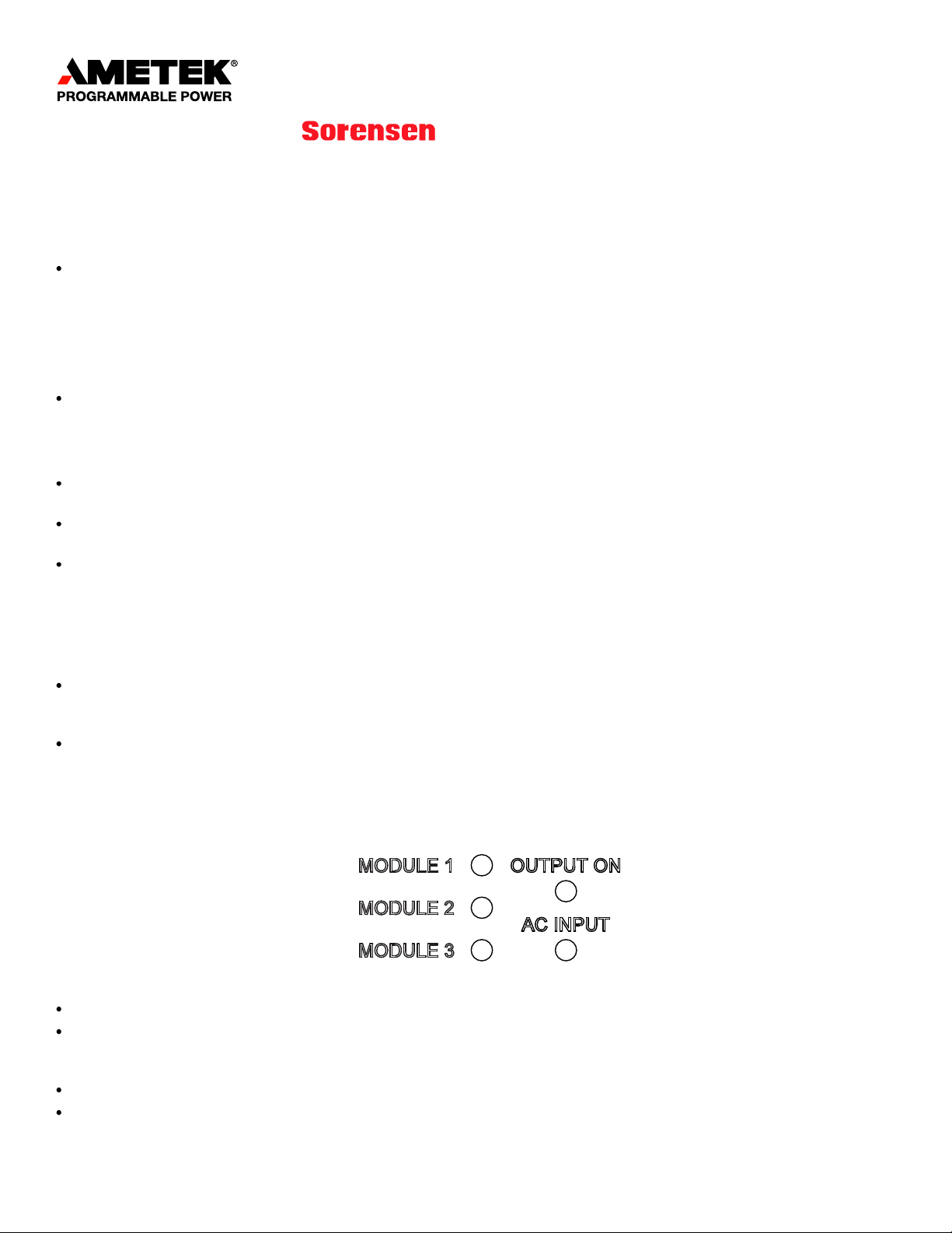
Visual indication of the power supply status is available via LEDs on the front panel.
Figure 1: LEDs on the front panel.
The LEDs labeled “MODULE 1/2/3” indicate the status of the respective modules within the power supply.
Module 1 is the module located, looking at the front panel, at the left side of the unit, module 2 is the module in the
center and module 3 is the module at the right side. Green lights indicate normal active operation. Red lights indicate
that the particular module has detected a warning or fault condition.
The LED labeled “OUTPUT ON” is green when the power supply has set the output to active mode.
The LED labeled “AC INPUT” is normally green. The LED is red when the power supply has detected an internal fault
or warning condition.
ASD 30kW Quick Reference Guide - rev X1 © 2011 AMETEK Programmable Power, Inc. All rights reserved. www.programmablepower.com
Page 2
PIN # PIN NAME
IN/OUT
DESCRIPTION
1
I_MON
OUT
a 0-10 VDC monitor signal (or 4-20 mADC) that indicates zero to full scale
output current
2
V_MON
OUT
a 0-10 VDC monitor signal (or 4-20 mADC) that indicates zero to full scale
output voltage
3
P_MON
OUT
a 0-10 VDC monitor signal (or 4-20 mADC) that indicates zero to full scale
output power
4
V_MODE_DOUT
OUT (*)
LO indicates the unit is not in voltage mode, HI indicates the unit is in voltage
mode if I_MODE is low. If both I_MODE and V_MODE are HI, it means power
mode.
5
I_MODE_DOUT
OUT (*)
LO indicates the unit is not in current mode, HI indicates the unit is in current
mode if V_MODE is low. If both I_MODE and V_MODE are HI, it means power
mode.
6
STATUS_DOUT
OUT (*)
LO indicates output disabled, HI indicates the output is enabled.
7
FAULT_DOUT
OUT (*)
LO indicates normal operation, HI indicates a fault.
8
DOUT_REF_IN
IN
Used to define the output high level of the digital outputs. If not connected, the
output high is 12V. If connected to 24Vdc, the output high is 24V.
9
GND
common
Same as pin 16
10
+24Vdc
OUT
+24VDC, same as pin 17
11
I_PROG_AIN
IN
a 0-10 VDC analog input signal (or 4-20 mADC) that programs zero to full
scale output current
12
V_PROG_AIN
IN
a 0-10 VDC analog input signal (or 4-20 mADC) that programs zero to full
scale output voltage
13
P_PROG_AIN
IN
a 0-10 VDC analog input signal (or 4-20 mADC) that programs zero to full
scale output power
If a “MODULE” LED is red but the “AC INPUT” is green, that means that there is a warning in the module but it is still
active, if the “AC INPUT” also turns red, it means that a module had a fault.
Isolated Analog Interface
The power supply output current, voltage, and power can be programmed and monitored via the 25 pin “ANALOG
INTERFACE” connector. The analog inputs and outputs can be configured (from the external switch and/or the digital
interface) to read or generate voltage or current signals. Full scale reference (0 to 10 VDC or 4 to 20mA) signal
represents full scale output current/voltage/power.
The analog and digital signals available in this interface are galvanically isolated from the power supply outputs. This
interface is not designed to withstand a high voltage potential with respect to earth ground.
If operating with current signals (4-20mA), the unit will generate a fault if any of the inputs has less than 2mA. By
default this fault will shut-down the unit, but this behavior can be changed from the digital interface.
If the unit is enabled via the analog interface, it will respond only to the analog setpoints and not to the digital interface
setpoints.
The full scale of the analog interface depends on the number of modules that are connected to the unit, both internal
and external modules. See Expected Number of Modules section for more details.
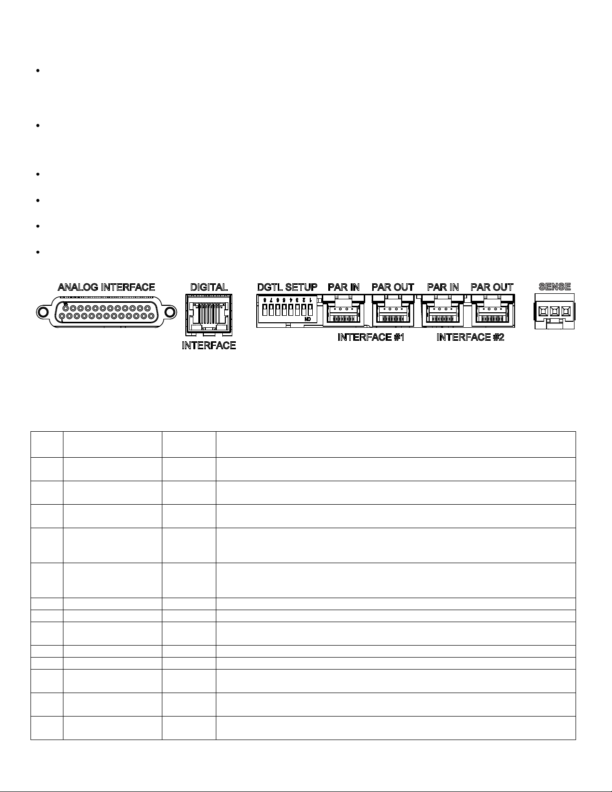
2
Figure 2: External interface on the rear panel.
The following two tables describe the available input and output signals at the DB25 connectors for standard ASD
units and the SG compatible interface.
Table 1: Analog interface signals. Standard ASD pin-out.
ASD 30kW Quick Reference Guide – rev X1 © 2011 AMETEK Programmable Power, Inc. All rights reserved. www.programmablepower.com
Page 3

PIN # PIN NAME
IN/OUT
DESCRIPTION
14
START/STOP_DIN
IN (**)
LO disables output, HI enables output.
15
RESET_DIN
IN (**)
LO to HI transition clears faults and warnings.
16
GND
common
Same as pin 9
17
+24Vdc
OUT
+24VDC, same as pin 10
1825
Not used.
PIN #
PIN NAME
IN/OUT
DESCRIPTION
1
Not used.
2
Not used.
Not used.
4
GND
common
5 ON/OFF
IN
LO = 0 VDC enables output, HI > 10 VDC disables output.
6
GND
common
7
I_MON
OUT
a 0-10 VDC monitor signal (or 4-20 mADC) that indicates zero to full scale
output current.
8
Not used.
9
Not used.
10
Not used.
11
Not used.
12
Not used.
13
Not used.
14
Not used.
15
V_PROG_AIN
IN
a 0-10 VDC analog input signal (or 4-20 mADC) that programs zero to full
scale output voltage.
16
I_PROG_AIN
IN
a 0-10 VDC analog input signal (or 4-20 mADC) that programs zero to full
scale output current.
17
FAULT_DOUT
OUT
LO = 0 VDC indicates normal operation, HI = 12 VDC indicates a fault.
18
Not used.
19
V_MON
OUT
a 0-10 VDC monitor signal (or 4-20 mADC) that indicates zero to full scale
output voltage.
20
Not used.
21
Not used.
22
Not used.
23
GND
common
24
GND
common
25
GND
common
Digital signal levels:
(*) Digital output low is 0V (<0.5V), output high is either 12V or 24V (+/-1V), depending on pin 8.
(**) Digital input low is 0.5V or lower, input high is 8V or higher.
Table 2: Analog interface signals. SG-compatible pin-out.
3
Digital Interface
The connector labeled DIGITAL INTERFACE is an RJ-45 connector that can be either an Ethernet port or an RS-485
half-duplex (2-wire) serial port with industry standard pin-out (pin 4 = RS485-B, pin 5 = RS485-A, pin 7 = 24Vdc, pin 8
= GND, the rest are not used).
The protocol to communicate with the units is MODBUS-TCP with the Ethernet port, or MODBUS-RTU with the serial
port. MODBUS-RTU over Ethernet is also available with the Ethernet port.
If the unit is enabled via the digital interface, it will respond only to the digital interface setpoints and not to the analog
port.
ASD 30kW Quick Reference Guide – rev X1 © 2011 AMETEK Programmable Power, Inc. All rights reserved. www.programmablepower.com
Page 4

Please see the Digital Programming Guide for details about how to control and monitor the power supply using the
digital port.
Parallel Interface
There are two parallel interfaces on the rear panel, labeled “INTERFACE #1” and “INTERFACE #2”. The connectors
labeled PAR IN and PAR OUT have identical signals and are used to facilitate the interconnection of several units in
daisy-chain.
The purpose of the 2 parallel interfaces is to allow the connection of modules inside the same chassis to different
loads. The modules are galvanically isolated from the rest of the system (master and other modules) so they can be
connected to loads at different potentials.
The parallel interface connectors are standard RJ-45. Shielded CAT 5 cables (STP) are required at this interface.
The signals at this interface are not Ethernet-compatible and they should not be connected to an Ethernet network. It
consists of an AMETEK proprietary digital bus, which is galvanically isolated from the modules.
All the modules must be connected to ONE active master to operate. Only the analog and digital interfaces of the
active master can be used to program and monitor the power supply.
In most of the models, all the 3 modules and the master are connected to Parallel Interface #1 (PI1), hence no
external connection is required to operate the modules within a single unit. If more than one unit is to be operated in
parallel, the unused masters must be disabled with the external switch (see external switches section).
There are ASD models that have one or more modules connected to Parallel Interface #2 (PI2). In this case these
modules do not communicate with the local master and they need to operate with a master in another unit. PI1 and
PI2 are completely independent and there is no connection between them, they are two different communication
buses.
When the units start-up, the active master will automatically perform a discovery of all the modules available in the
bus (internal to the unit and external). After the modules are discovered, they are ready to operate (green LED). If a
module is not discovered, its LED will turn red until it is discovered by an active master.
In order to be able to operate in parallel, all the modules within a parallel interface bus must be of same output
voltage. If a module of different voltage is connected to the PI, it will not be discovered and will turn the red light.
Parallel interconnection of some different part numbers :
ASD 60-60-60 and ASD 40-40-40: ALL the modules are connected to PI1. PI2 has NO module connected so
do not use it.
ASD 60-00-60: Module #1 is connected to PI1, and module #3 to PI2. To operate module #2 it must be
connected to an active master in another chassis. If the local master is disabled, also module #1 must be
connected to an active master in another chassis.
ASD 40-60-60: In this unit, the 40V module is connected to PI1 and the 60V modules are connected to PI2.
To operate the 60V modules they must be connected to an active master in another chassis.
The parallel interfaces need bus termination on both ends, which are provided with the units. In the case of not
connecting any unit in parallel (single unit operation), there must be at least one bus termination, otherwise the unit
will not operate.
4
ASD 30kW Quick Reference Guide – rev X1 © 2011 AMETEK Programmable Power, Inc. All rights reserved. www.programmablepower.com
Page 5

Switch number
Description
1
DOWN (on) = 0 – 10 VDC monitor signals and analog programming references
UP (off) = 4 – 20 mADC monitor signals and analog programming references. If the input current
is lower than 2 mA, the unit will generate a fault.
2
DOWN (on) = remote voltage sense disabled.
UP (off) = remote voltage sense enabled.
3
DOWN (on) = master enabled (sets the master as active).
UP (off) = master disabled (the modules in the chassis will operate with an external master).
4 to 7
Unit address or expected number of modules, depending on switch 8.
Use these switches to define a binary number from 0 to 15 (1111 in binary), switch 4 is the least
significant bit and switch 7 the most significant.
DOWN (on) is a binary ZERO
UP (off) is a binary ONE
The unit address or expected number of modules will be the binary value plus one (giving a
range of 1 to 16).
8
DOWN (on) = switches 4-7 are used to set the unit address, necessary for the digital interface.
UP (off) = switches 4-7 are used to indicate the power supply how many modules it should
expect to discover. For more details please see the description of the expected number of
modules feature.
External Switches
The eight position DIP switch labeled DGTL SETUP is used for power supply configuration. The following table lists each
position and its function
5
Expected number of modules feature
When this feature is enabled (switch #8 UP or from the digital interface) the master will expect to discover a
predefined number of modules. If the number of modules is lower than the expected, the unit will generate a fault
indicating that there may be a problem with one or more modules. This feature also fixes the analog interface scale
based on the expected number of modules, making it independent from the actual number of modules that were
discovered.
For example, if in a 60V unit the predefined number of modules is 6 (switches 6 and 4 UP), the total available output
current with 6 modules would be 1000A, so the analog interface full scale (10V or 20mA) would be 1000A regardless
of the actual number of connected modules. If there are 3 discovered modules because the 2nd chassis was not
powered-up, the analog interface scale will be fixed based on the EXPECTED number of modules, and the master will
generate a fault because there were too few discovered modules.
If this feature is not used, the actual number of modules discovered by the master will define the analog interface
scale. For example, three 60 V modules give 500 A full scale, or six 60 V modules give 1000 A.
ASD 30kW Quick Reference Guide – rev X1 © 2011 AMETEK Programmable Power, Inc. All rights reserved. www.programmablepower.com
 Loading...