

Page 1

Reference Manual
Advanced Signal Calibrator
ASC-400
Page 2

Reference Manual
Advanced Signal Calibrator
JOFRA ASC-400
Copyright 2014 AMETEK Denmark A/S
Page 3
About this manual….
The structure of the manual
This reference manual is aimed at users who are familiar with AMETEK signal calibrators,
as well as those who are not. The manual is divided into 12 chapters, which describe how
to set up, operate, service and maintain the signal calibrator. The technical specifications
are described and accessories may be ordered from the list of accessories.
Safety symbols
This manual contains a number of safety symbols designed to draw your attention to
instructions, which must be followed when using the instrument, as well as any risks
involved.
Warning
Conditions and actions that may compromise the safe use of the instrument and
result in considerable personal or material damage.
Caution…
Conditions and actions that may compromise the safe use of the instrument and
result in slight personal or material damage.
Note…
Special situations, which demand the user’s attention.
128797 03 2015-04-22 2
Page 4

List of contents
1.0 Introduction ..................................................................................................................................... 5
1.1 Warranty ..................................................................................................................................................... 6
1.2 Receiving the Advanced Signal Calibrator ................................................................................................. 6
1.3 Dimensioning drawing ................................................................................................................................ 7
2.0 Safety instructions .......................................................................................................................... 8
3.0 Calibrator Interface ....................................................................................................................... 10
3.1 Input/Output Connections ......................................................................................................................... 10
3.2 Keypad - Functions ................................................................................................................................... 11
3.3 Main display - Functions ........................................................................................................................... 11
3.4 Upper display (Read-back display) - Functions ........................................................................................ 12
3.5 Lower display (Primary display) – Functions ............................................................................................ 12
4.0 Operating the calibrator ................................................................................................................ 13
4.1 Basic operation (Setup) ....................................................................................................... ..................... 13
4.2 The principle of navigating through a Setup ............................................................................................. 14
4.3 System Settings ........................................................................................................................................ 15
4.3.1 Power Saver (Auto off) ................................................................................................................. 16
5.0 Using measure modes (lower display) ........................................................................................ 18
5.1 Measuring volts ......................................................................................................................................... 18
5.2 Measuring frequency ................................................................................................................................ 19
5.3 Measuring mA ........................................................................................................................................... 20
5.4 Measuring Temperature ........................................................................................................................... 21
5.4.1 Using Thermocouples (TC) .......................................................................................................... 21
5.4.2 Using Resistance-Temperature-Detectors (RTDs) ...................................................................... 22
5.5 Measuring Pressure .................................................................................................................................. 25
5.5.1 Zeroing with Absolute Pressure Modules (APM S, H and Mk.II) ................................................. 26
5.5.2 Using the BARO Module (optional) .............................................................................................. 26
6.0 Using Source modes (Lower Display) ......................................................................................... 28
6.1 Sourcing mA (internal loop power supply) ................................................................................................ 28
6.2 mA Sink (external loop power supply) ...................................................................................................... 29
6.3 Sourcing Voltage ....................................................................................................................................... 30
6.4 Sourcing Frequency .................................................................................................................................. 31
6.5 Sourcing a Pulse Train ............................................................................................................................. 31
6.6 Sourcing mV ............................................................................................................................................. 32
6.7 Sourcing Thermocouples .......................................................................................................................... 33
6.8 Sourcing Ohms/RTDs ............................................................................................................................... 34
6.9 Custom RTD ............................................................................................................................................. 35
6.10Using Auto Output functions ..................................................................................................................... 36
6.10.1 Using the Step function ................................................................................................................ 36
6.10.2 Using the Ramp function .............................................................................................................. 37
7.0 Using Isolated Measure Modes (Upper Display) ........................................................................ 39
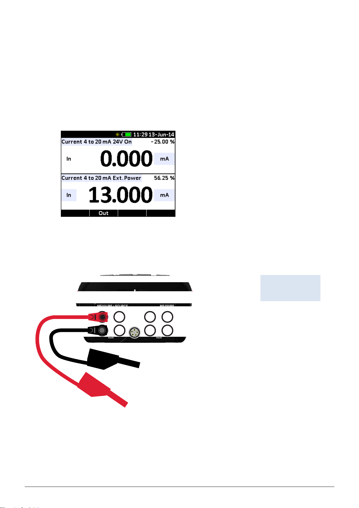
7.1 Measuring mA (external loop supply) ....................................................................................................... 39
7.2 Measuring current with internal loop power .............................................................................................. 40
7.3 Measuring Voltage .................................................................................................................................... 41
7.4 Measuring Pressure .................................................................................................................................. 41
8.0 Using the Upper and Lower Display for Calibration and Testing ............................................ 43
8.1 Performing a Temperature Switch Test .................................................................................................... 43
8.2 Performing a Pressure Switch Test .......................................................................................................... 45
8.3 Testing an Input or Indicating Device ....................................................................................................... 47
8.4 Calibrating an I/P Device .......................................................................................................................... 47
8.5 Calibrating a Transmitter (Signal Converter) ............................................................................................ 49
8.6 Calibrating a Pressure Transmitter (loop powered 4-20 mA) ................................................................... 50
128797 03 2015-04-22 3
Page 5

8.7 Using Scaled Current or Voltage when testing or calibrating a T/I Transmitter ..................................... 52
8.8 Using Percent Error when testing or calibrating a T/I Transmitter ............................................................ 53
9.0 Maintenance ................................................................................................................................... 54
9.1 Returning the calibrator to service ............................................................................................................ 54
9.2 Replacing batteries ................................................................................................................................... 56
9.3 Storing ....................................................................................................................................................... 57
9.4 Cleaning .................................................................................................................................................... 57
10.0 Errors .............................................................................................................................................. 58
11.0 Technical specifications ............................................................................................................... 59
12.0 List of accessories ........................................................................................................................ 67
128797 03 2015-04-22 4
Page 6

1.0 Introduction
Congratulations on your new AMETEK JOFRA Advanced Signal Calibrator!
With the AMETEK JOFRA Advanced Signal Calibrator, you have chosen an extremely
effective instrument, which we are sure will perform according to your expectations.
This ASC-400 signal calibrator is a handheld, battery or DC adaptor powered instrumen t
that measures and sources electrical and physical parameters.
During the past several years, we have acquired extensive knowledge of industrial
signal calibration. This expertise is reflected in our products, which are all designed for
daily use in an industrial environment. Please note that we would be very interested in
hearing from you if you have any ideas or suggestions for changes to our products.
This reference manual applies to the following instrument:
JOFRA ASC-400
The calibrator has the following features and functions:
A dual colour display.
The upper display is used for the measurement of volts, current, pressure, %error,
scaling and switch test
The lower display can be used to measure and source volts, millivolts, current, pressure,
resistance, resistance temperature detectors (RTDs), thermocouples, frequency, and
resistance, and to source pulse trains.
A thermocouple (TC) input/output terminal with automatic and manual reference-junction
(co l d j u n c t i o n ) temperature compensation.
An interactive and intuitive user interface
USB interface for remote control
Isolated read back for transmitter calibration.
A BARO option turning any gauge measuring APM into an absolute measuring
device.
Extended and comprehensive pressure measurement capabilities with JOFRA
advanced pressure modules (APM)
ISO-9001 certified
AMETEK Denmark A/S was ISO-9001 certified in September 1994 by Bureau Veritas
Certification Denmark.
CE-label
Your new signal calibrator bears the CE label and conforms to the EMC
Directive.
128797 03 2015-04-22 5
Page 7

Technical assistance
Please contact the dealer from whom you acquired the instrument if you require
technical assistance.
1.1 Warranty
This instrument is warranted against defects in workmanship, material and design for
two (2) years from date of delivery to the extent that AMETEK will, at its sole option,
repair or replace the instrument or any part thereof which is defective, provided,
however, that this warranty shall not apply to instruments subjected to tampering or,
abuse, or exposed to highly corrosive conditions.
THIS WARRANTY IS IN LIEU OF ALL OTHER WARRANTIES WHETHER EXPRESS
OR IMPLIED AND AMETEK HEREBY DISCLAIMS ALL OTHER WARRANTIES,
INCLUDING, WITHOUT LIMITATION, ANY WARRANTY OF FITNESS FOR A
PARTICULAR PURPOSE OR MERCHANTABILITY. AMETEK SHALL NOT BE LIABLE
FOR ANY INCIDENTAL OR CONSEQUENTIAL DAMAGES, INCLUDING, BUT NOT
LIMITED TO, ANY ANTICIPATED OR LOST PROFITS.
This warranty is voidable if the purchaser fails to follow any and all instructions,
warnings or cautions in the instrument’s User Manual.
If a manufacturing defect is found, AMETEK will replace or repair the instrument or
replace any defective part thereof without charge; however, AMETEK’s obligation
hereunder does not include the cost of transportation, which must be borne by the
customer. AMETEK assumes no responsibility for damage in transit, and any claims for
such damage should be presented to the carrier by the purchaser.
1.2 Receiving the Advanced Signal Calibrator
When you receive the instrument…
1) Unpack and check the signal calibrator and the accessories carefully.
2) Check the parts according to the list shown below.
If any of the parts are missing or damaged, please contact the dealer who sold you
the signal calibrator.
You should receive:
1 ASC-400 Calibrator
1 electronic Reference manual on USB memory stick
2 sets of test leads and test clips (black and red)
1 carrying soft bag
1 USB cable
6 x AA batteries
1 Calibration certificate (International traceable)
When reordering, please specify the part numbers according to the list of accessories,
section 12.0
128797 03 2015-04-22 6
Page 8
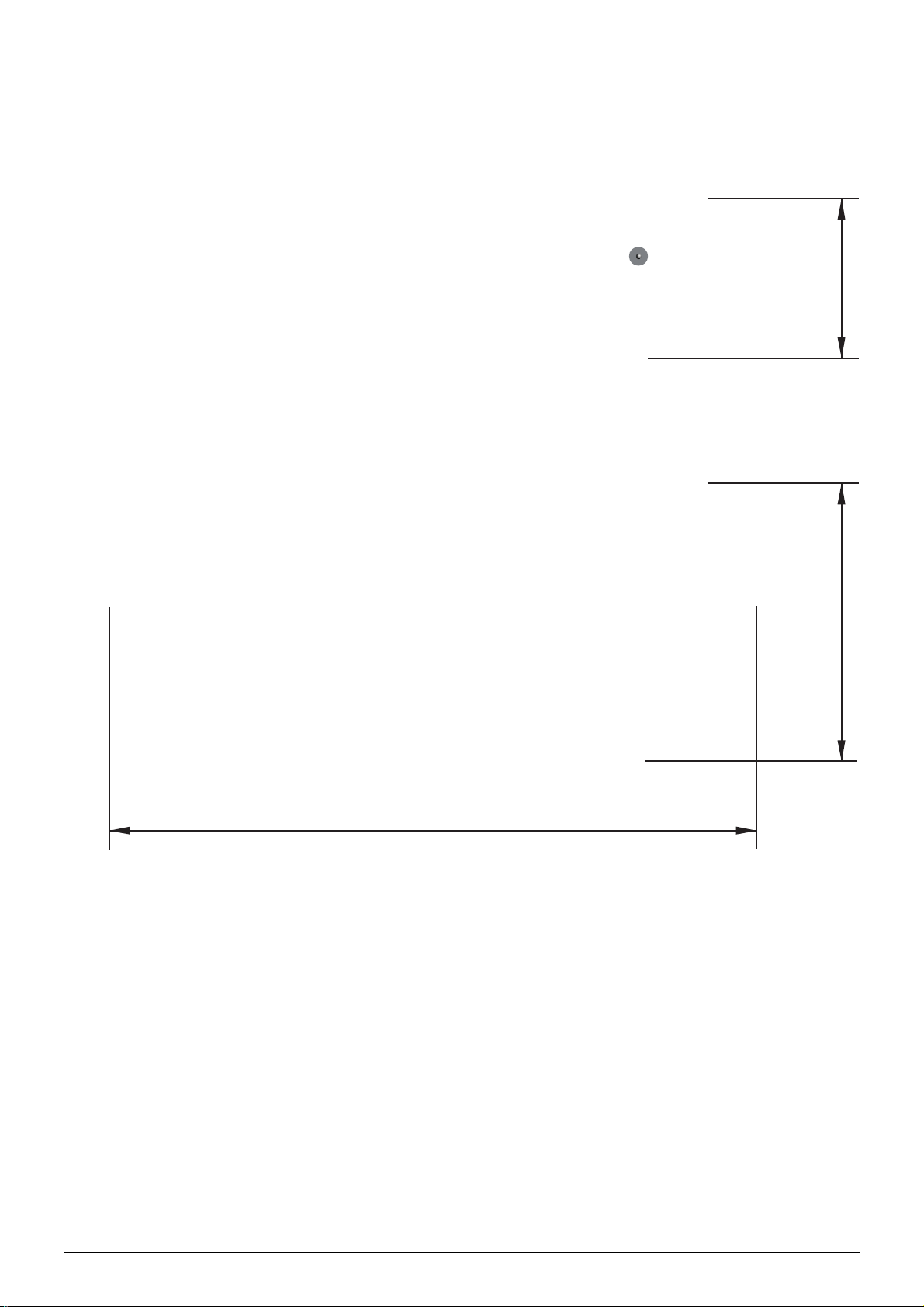
1.3 Dimensioning drawing
55 mm96 mm
220 mm
128797 03 2015-04-22 7
Page 9

2.0 Safety instructions
Read this manual carefully before using the instrument!
Please follow the instructions and procedures described in this manual. They are
aimed at allowing you to make the best of your signal calibrator and avoid any
personal injuries and/or damage to the instrument.
Disposal – WEEE Directive
The signal calibrator contains Electrical and Electronic circuits and must be properly
recycled or disposed of (in accordance with the WEEE Directive 2002/96/EC).
Warning
The signal calibrator is designed to calibrate and measure low voltage process signals.
To ensure the safety of the operator and the instrument, DO NOT connect the signal
calibrator to input voltages above 30 Volts.
To avoid possible electric shock or personal injury:
Do not apply more than the rated voltage. See specifications for supported ranges.
Follow all equipment safety procedures.
Ne v e r t o u c h the pr o b e t o a voltag e so u r c e w he n t he te s t l ea ds ar e plugged into the
current terminals.
Do not use the calibrator if it is damaged. Before you use the calibrator, inspect the
case. Look for cracks or missing plastic. Pay particular attention to the insulation
surrounding the connectors.
Select the proper function and range for your measurement.
Make sure the battery cover is closed and latched before you operate the calibrator.
Remove test leads from the calibrator before you open the battery door.
Inspect the test leads for damaged insulation or exposed metal. Check tes t leads
continuity. Replace damaged test leads before you use the calibrator.
When using the probes, keep your fingers away from the probe contacts. Keep your
fingers behind the finger guards on the probes.
Connect the common test lead before you connect the live test lead.
When you disconnect test leads, disconnect the live test lead first.
Do not use the calibrator if it operates abnormally. Protection may be impaired. When
in doubt, have the calibrator serviced.
Do not operate the calibrator around explosive gas, vapour, or dust.
When using a pressure module, make sure the process pressure line is shut off
and depressurized before you connect it or disconnect it from the pressure module.
Disconnect test leads before changing to another measure or source function.
When servicing the calibrator, use only specified replacement parts.
To avoid false readings, which could lead to possible electric shock or personal injury,
replace the battery as soon as the battery indicator appears.
To avoid a violent release of pressure in a pressurized system, shut off the valve and
slowly bleed off the pressure before you attach the pressure module to the
pressure line.
To avoid personal injury or damage to the calibrator, use only the specified
replacement parts and do not allow water into the case.
128797 03 2015-04-22 8
Page 10

Caution…
To avoid possible damage to the signal calibrator or to the equipment under
test:
Disconnect the power and discharge all high-voltage capacitors before testing
resistance or continuity.
Use the proper jacks, function, and range for your measurement or sourcing
application.
If the message changes to "OL" the range limit is exceeded and the pressure source
must immediately be removed from the APM to prevent damage to the pressure
transducer inside.
To avoid damaging the pressure module from overpressure, never apply pressure
above the rated maximum printed on the module.
To avoid damaging the plastic lens and case, do not use solvents or abrasi ve
cleansers.
When using the switch test function, make sure that no other equipment, such as
heavy loads or sources, is connected in the test loop.
Note…
The product liability only applies if the instrument is subject to a manufacturing
defect. This liability becomes void if the user fails to follow the maintenance
instructions described in this manual or uses unauthorized spare parts.
128797 03 2015-04-22 9
Page 11
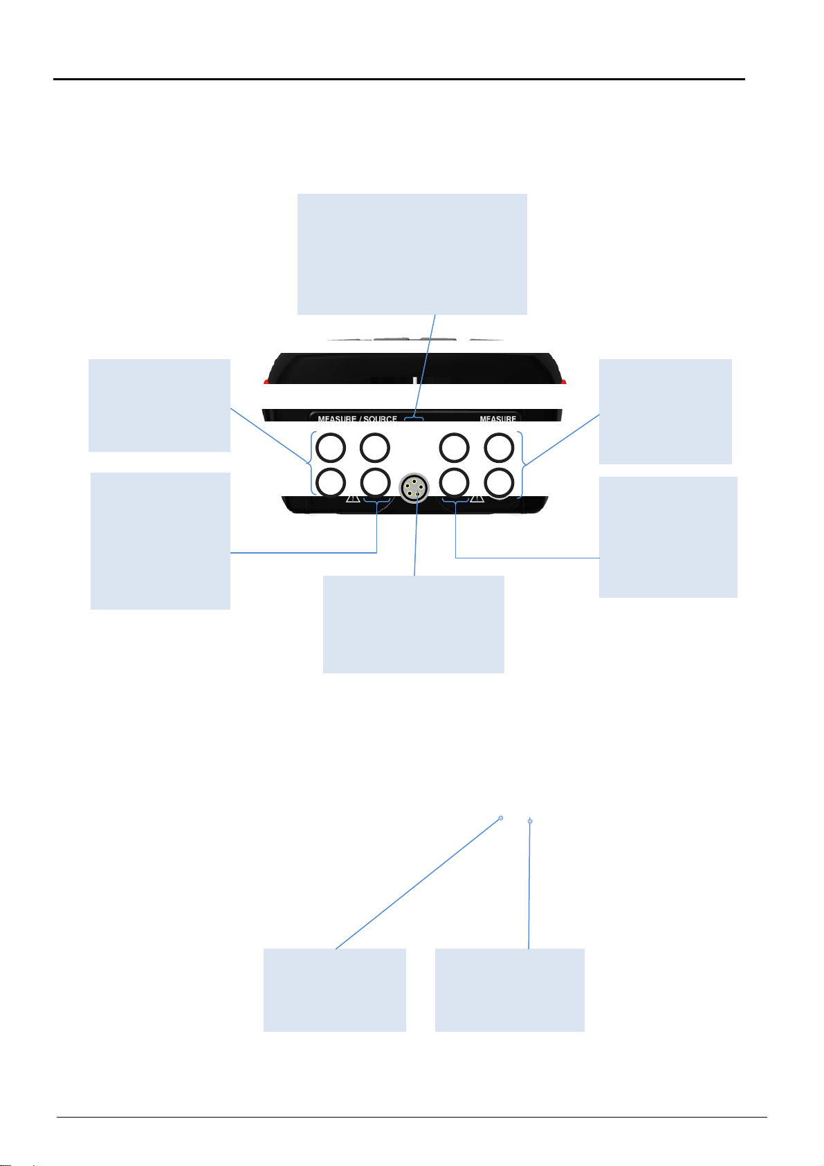
3.0 Calibrator Interface
ying
3.1 Input/Output Connections
Measure / Source
mA
Input terminals for
sourcing and
measuring current.
Measure / Source
V, Ω/RTD, Hz
Input terminals for
sourcing and
measuring voltage,
frequency, pulse
train, resistance
and RTDs.
TC mV input / output
Terminal for measuring or
simulating thermocouples and mV.
Accepts miniature polarized
thermocouple plugs with flat in-line
blades spaced 7.9 mm (0.312 in)
center to center.
Pressure module
connector (APM)
Connects calibrator to a
pressure module for
pressure measurements.
USB connection
Connects calibrator
to a PC for remote
control.
Charger Connector
Connects to optional
power supply /
battery charger.
Measure / V mA
Input terminals for
measuring ,
switch test,
current, voltage
and suppl
Measure Ω/RTD,
4w, 3/4w
Input terminals for
performing RTD
measurements
with 3-wire or 4wire setups.
128797 03 2015-04-22 10
Page 12
3.2 Keypad - Functions
Power key/
Backlight key
Turn the calibrator on and
off. Press the button for
five seconds to turn it off.
Adjust the backlight
intensity.
Arrow Keys
Have different functions
depending on the mode of
operation. In navigation
mode, they move the
cursor in the desired
direction.
In edit mode, they roll in
the list of options or if
entering a number, the
arrow left and arrow right
move the cursor one
character in the desired
direction.
Zero key
Zero Pressure Module
reading.
Function keys
F1, F2, F3, F4
To operate the menu bar
at the bottom of the
calibrator display, use the
F-keys.
Back key
Cancel a selection / edit or
return to previous menu.
Action key / Enter key
Action function: Open and
close edit fields or a menu
button. The action key also
accepts the selected
option or entered value.
Enter function: Accept
selected options or
entered values. When a
value is entered with the
Enter Key the cursor
selects the next value field
in the list.
Numeric Keypad
Allows user to enter
Numeric values in both
upper and lower display.
3.3 Main display - Functions
Remaining power and
attached power adapter
Real Time
Clock display
Configuration key
Opens and closes
configuration mode.
Date displayBattery icon.
Upper display
The upper display is used
for measuring DC voltage,
DC current with and
without loop power,
pressure, percent, error,
scaled value, switch test.
Lower display
The lower display can be
used for both measuring
and sourcing.
Horizontal menu bar
The menu bar is used to
setup both the upper and
the lower display to perform
the desired function. The
function keys (F1, F2, F3
and F4) are used to
navigate through all the
levels and choices of the
menu bar.
128797 03 2015-04-22 11
Page 13
(opt.)
3.4 Upper display (Read-back display) - Functions
Primary Parameters
Determine what parameter is
goin g t o b e measure d.
The available options for the
upper display are : CURRENT,
VOLTAGE, SWITCH TEST,
PRESSURE and LEAK TEST.
Additional parameters
Selection and selection of
parameters relevant to the
choice of primary parameter
Numeric display
Displays the numeric values
of the signa l being
measured.
An “OL” reading indicates an
out of range or overload
condition.
Backlight Intensity
Indicates Low, Medium or
High intensity on backlight
Secondary upper display
Shows where in the preset
span the measured value
falls. Fixed for mA at 4 (0%)
and 20 (100% ). Also shows
mA value for percent error,
mA or Volts value for scaling
and leak rate for pressure.
Units
Shows what unit the
measurement value is in.
Available options are : mA,
SCALING, %ERROR, VOLT
and PRESSURE UNITS.
3.5 Lower display (Primary display) – Functions
Primary Parameters
Determine what parameter is
goin g to be measured or
sourced.
The available options for the
upper display are : CURRENT,
VOLTAGE, THERMOCOUPLE, RTD, OHMS,
FREQUENCY, PULSE,
PRE S S U R E and BARO
Input / Output
Switches / indicates lower
display input mode (read),
and output mode (source).
Numeric display
Displays the numeric values
of the signa l being
measured, or sourced.
An “OL” reading indicates an
out of range or overload
condition.
128797 03 2015-04-22 12
Additional parameters
Selection and selection of
parameters relevant to the
choice of primary parameter.
Native Value
0 to 100 % in mA out mode
and leak rate for pressure.
Units
Shows what unit the
measurement or source
value is in.
Page 14
4.0 Operating the calibrator
4.1 Basic operation (Setup)
Warning
Please inspect the Safety Instructions in section 2.0 before using the instrument.
Caution…
Please inspect the Safety Instructions in section 2.0 before using the instrument.
Connect USB cable and APM before switching on the instrument, or before applying
DC power.
1. Select mode for upper and lower display (RED markers).
2. Select the related options and functions for the selected modes (BLUE markers)
Note…
the light blue fields; they indicate a parameter / function that can be selected
or altered in edit mode. This works like a build in user manual, indicating the
changeable parameters for the selected mode at all times.
128797 03 2015-04-22 13
Page 15
4.2 The principle of navigating through a Setup
ACTION SCREEN DISPLAYED
1. Press to access edit mode.
2. Use the (ARROW) keys to move between the
parameter fields.
3. Press to access the various Parameter lists to
choose from.
4. Start by selecting upper or lower display.
5. Use the (ARROW) keys to move between the
parameter fields and make more changes…
6. Press to accept the selections and leave the
edit mode.
7. Use the numeric keys to enter an output value (if output
if chosen).
8. Press to accept the value.
9. Or use the (ARROW) keys to enter “fine adjust”
mode.
Move the value-frame to the right or left using the
or keys. Modify the digits using the or keys.
128797 03 2015-04-22 14
Page 16
4.3 System Settings
The System Settings setup can be accessed at any stage of operation:
1. Press to display the Horizontal menu bar.
2. Press (System) to access the System Settings.
F3
3. Use the (ARROW) keys to move between the setting fields.
4. Press to open a setting field for editing.
5. Use the numeric keys to enter the desired value and press to accept the value.
When entering the HART Resistor ON/OFF field and Date field horizontal lists
appear.
6. Use the and keys to scroll in the lists and select from the lists by pressing .
7. Press either or to exit the System Settings.
128797 03 2015-04-22 15
Page 17
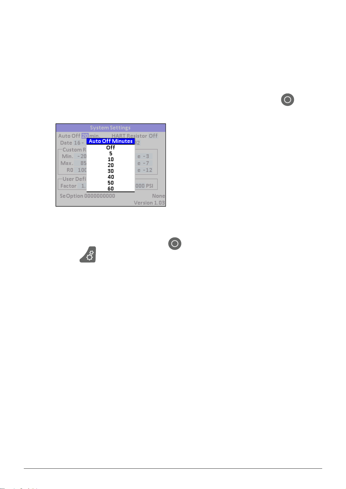
8. The calibrator resumes normal operation after a few seconds. It will return to the
setup last used.
4.3.1 Power Saver (Auto off)
The ASC-400 calibrator automatically turns off 5 to 60 minutes after the last keystroke.
To reduce or increase this time or to disable this feature, do as follows:
1. In the System Settings setup enter the “Auto Off” setting field and press to
access the Auto Off Minutes list.
2. The list displays the turn-off time in minutes.
Off disables the power saver and the calibrator will be permanently off.
3. Select the turn-off time by pressing .
4. Press to exit the System Settings.
128797 03 2015-04-22 16
Page 18
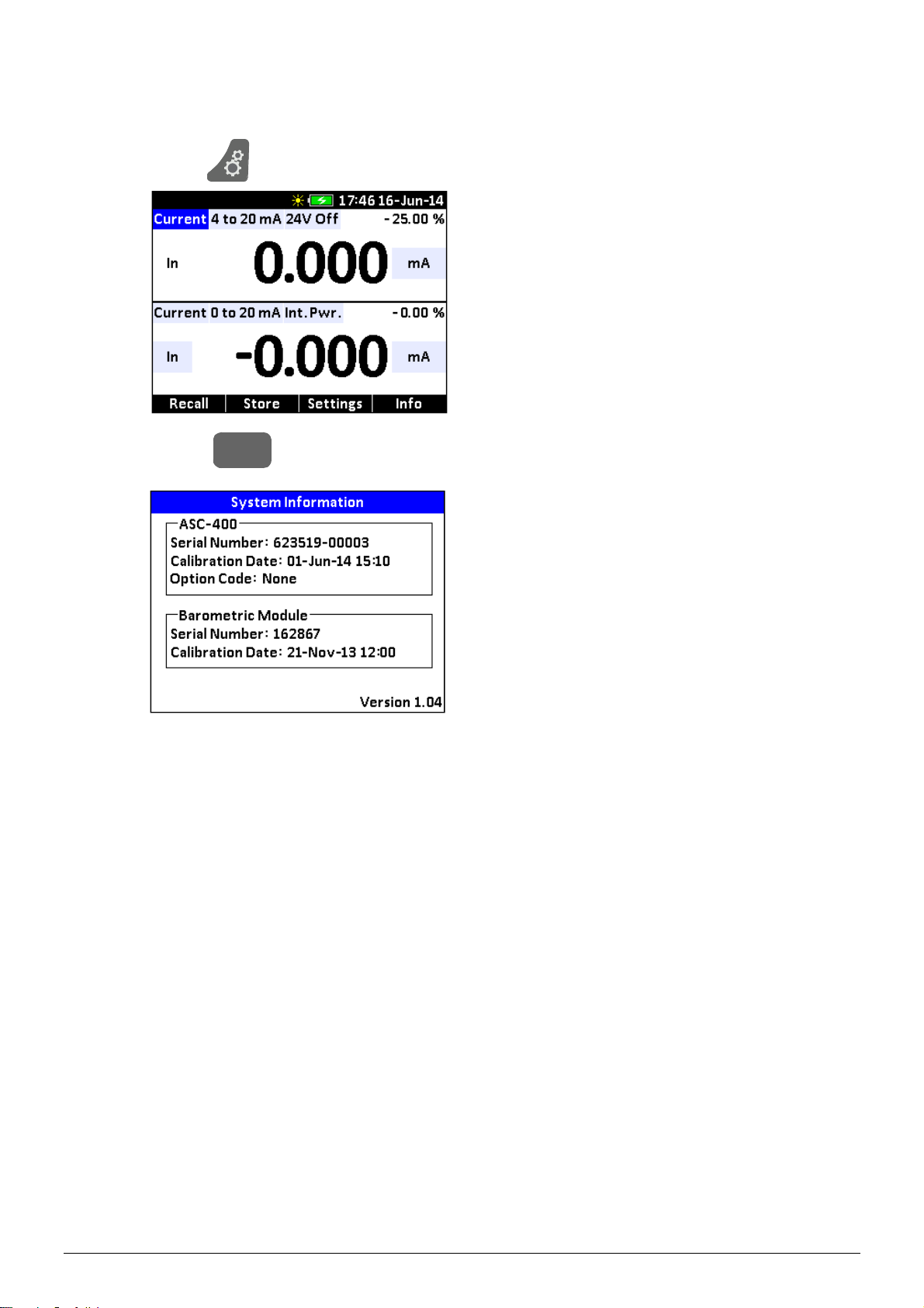
4.4 System Information
The System Information can be accessed at any stage of operation:
1. Press to display the Horizontal menu bar.
2. Press (Info) to access the System Information.
F4
128797 03 2015-04-22 17
Page 19
5.0 Using measure modes (lower display)
5.1 Measuring volts
The electrical parameter volts can be measured using the lower display.
To make the desired measurements, follow the principle of navigating through the
functions described in the guidelines in section 4.2 and proceed as follows:
1. Select “Voltage” from the Lower Mode list.
2. Select the desired Range from the Range list.
3. Select the desired Test Mode (in) from the Test Mode list.
4. Accept the selections and leave the edit mode.
5. Connect the leads, as shown in Figure 1.
Figure 1
Measuring Volts
128797 03 2015-04-22 18
Page 20
5.2 Measuring frequency
The electrical parameter frequency can be measured using the lower display.
To make the desired measurements, follow the principle of navigating through the
functions described in the guidelines in section 4.2 and proceed as follows:
1. Enter edit mode.
2. Select “Frequency” from the Lower Mode list.
3. Select the desired Test Mode (In) from the Test Mode list.
4. Enter the desired trigger level (Trig. V) value using either the ARROW keys or the
numeric keys.
5. Select the desired unit from the Units list.
6. Accept the selections and leave edit mode.
7. Connect the leads, as shown in Figure 2.
Figure 2
Measuring Frequency
128797 03 2015-04-22 19
Page 21
5.3 Measuring mA
The electrical parameter mA can be measured using the lower display.
Follow the principle of navigating through the functions as described in the guidelines in
section 4.2 to make the desired mA measurements:
1. Enter edit mode.
2. Select “Current” from the Lower Mode list.
3. Select the desired Test Mode (In) from the Test Mode list.
4. Select the desired Range from the Range list.
5. Select the desired power source from the Power Source list.
6. Select mA or % from the Units list.
7. Accept the selections and leave edit mode.
8. Connect the leads, as shown in Figure 3.
Figure 3
Measuring mA
128797 03 2015-04-22 20
Page 22

5.4 Measuring Temperature
5.4.1 Using Thermocouples (TC)
The ASC-400 supports the following thermocouple types:
B, BP, C, E, J, K, L, N, R, S, T, U, XK
The characteristics of all the types are described in section 11 – Technical
Specifications.
The ASC-400 has 3 cold junction Modes to choose from:
CJ Auto Automatic CJ compensation, CJ temperature inside the
connector is measured by a high accuracy RTD.
CJ Off With CJ in OFF Mode, the calibrator will measure the difference
between the thermocouple at the junction and at its TC input
terminal (equivalent to 0ºC CJ).
CJ Manual With CJ in Manual Mode it is possible to set the desired CJ
temperature to be used for temperature calculation.
Note…
CJ Off Mode should only be used when calibration is being done using an
external ice bath.
CJ Manual mode should be used when the cold junction temperature is known,
but different from 0 º C .
To use the thermocouple to measure temperature, follow the principle of navigating
through the functions described in the guidelines in section 4.2 and proceed as follows:
1. Attach the thermocouple leads to the TC mini plug, and insert the plug into the
input/output of the ASC-400 calibrator, as shown in Figure 4.
2. Enter edit mode.
3. Select “Thermocouple” from the Lower Mode list.
4. Select the desired Test Mode (In) from the Test Mode list.
5. Select TC function from the TC Type list.
6. Select CJ Mode from the list.
7. If CJ Manual is selected a CJ temperature value must be entered using either the
ARROW keys or the numeric keys.
8. Select the temperature unit from the Units list.
128797 03 2015-04-22 21
Page 23

9. Accept the selections and leave edit mode.
Figure 4
Measuring Temperature using
Thermocouple Terminals
Note…
For best accuracy wait minimum 2 to 5 minutes for the temperature between the
mini plug and the calibrator to stabilize before any measurements are taken .
Use the appropriate type of TC connector, using a wrong type of mini TC connector will
cause additional CJ error.
The ASC-400 calibrator can also measure the mV of a Thermocouple, which can be
used along with a table in case the corresponding TC type is not supported by the
calibrator.
To select mV do as follows:
1. Select “Voltage” from the Lower Mode list.
2. Select “-10 to 75 mV” from the Range list.
In this mode the CJ compensation is turned off.
Note…
The TC wire used must match the thermocouple type being calibrated.
5.4.2 Using Resistance-Temperature-Detectors (RTDs)
The supported types of RTDs are shown in Section 11 - Specifications.
RTDs are characterized by their 0°C resistance, R0. The ASC-400 calibrator accepts
two, three, and four wire inputs, with four wire input being the most accurate.
To use the RTD option, follow the principle of navigating through the functions described
in the guidelines in section 4.2 and proceed as follows:
1. Enter edit mode.
2. Select “RTD” from the Lower Mode list.
3. Select “In” from the Test Mode list.
4. Select RTD type from the RTD Type list.
5. Select a wire connection from the Num. Wires list. 4-wire allows for the most precise
measurement.
6. Accept the selections and leave edit mode.
128797 03 2015-04-22 22
Page 24

7. Attach RTD leads, as shown in Figure 5
Figure 5
Measuring RTD temperature
2, 3 or 4 wire connections
RTD
2 wire
RTD
3 wire
RTD 4 wire
128797 03 2015-04-22 23
Page 25

Resistance can also be measured using this function:
1. Select “Resistance” from the Lower Mode list.
2. Proceed as in the above guidelines.
This option can be used to measure ohms or a type resistive temperature sensor, which is
not programmed into the ASC-400 calibrator.
128797 03 2015-04-22 24
Page 26

5.5 Measuring Pressure
Warning
To avoid a violent release of pressure in a pressurized system, shut off the valve and
slowly bleed off the pressure before you attach the pressure module to the pressure
line.
Caution…
To avoid damaging the pressure module from overpressure, never apply pressure
above the rated maximum printed on the module.
To avoid damaging the pressure module from corrosion, use it only with specified
materials. Refer to the pressure module documentation for material compatibility.
To measure pressure, follow the principle of navigating through the functions described
in the guidelines in section 4.2 and proceed as follows:
1. Connect the pressure module to the ASC-400 calibrator, as shown below in Figure
6.
Note…
The APM might take a while to start up. The module is a complete pressure
measuring system with a microcontroller system inside.
The calibrator can measure pressure on both the upper and the lower display. This
makes it possible to measure pressure in two different units at the same time.
2. Select either the upper or lower display to work from.
3. Select “Pressure” from the Upper or Lower Mode list.
4. Select type of pressure, Gauge or Absolute (If barometer is mounted in ASC-400).
5. Select the desired measuring unit from the Units list.
6. Zero the pressure module (see section 5.5.1 for using the zeroing function).
7. Leak rate is automatically calculated in the selected pressure unit / minute.
128797 03 2015-04-22 25
Page 27

APM pressure module
Figure 6
Connections for Measuring
Pressure
5.5.1 Zeroing with Absolute Pressure Modules (APM S, H and Mk.II)
To zero, adjust the calibrator to read a known pressure, such as barometric pressure.
To adjust the calibrator, follow the principle of navigating through the functions described
in the guidelines in section 4.2 and proceed as follows:
1. Select either the upper or lower display to work from.
2. Select “Pressure” from the Upper or Lower Mode list.
3. Press to activate the Zeroing.
ZERO
4. The calibrator stores the Barometric zero offset in non-volatile memory.
The zero offset is stored for one absolute pressure module at a time. If a new
absolute module is connected this process must be repeated.
5.5.2 Using the BARO Module (optional)
1. The BARO barometer option in the ASC-400 calibrator has 2 functions.
Working as a high accuracy barometer
Applying the barometric pressure value to the measurement of a pressure
module (APM) allowing any gauge APM to be used for absolute measurements.
This system is superior to ordinary absolute sensors, as the working sensor is
gauge and can be zeroed at any time, compensating for potential drift.
128797 03 2015-04-22 26
Page 28

2. If the BARO option is mounted, the pressure type field becomes active and
pressure type can be selected.
128797 03 2015-04-22 27
Page 29

6.0 Using Source modes (Lower Display)
The ASC-400 calibrator can generate calibrated signals for testing and calibrating process
instruments. The calibrator can source voltages, currents, resistances, frequencies,
pulses, and the electrical output of RTD and thermocouple temperature sensors.
6.1 Sourcing mA (internal loop power supply)
To source a current, follow the principle of navigating through the functions described in
the guidelines in section 4.2 and proceed as follows:
1. Select “Current” from the Lower Mode list.
2. Select “Int. Pwr.” from the Power Source list.
3. Select “Out” from the Test Mode list.
4. Connect leads to the mA terminals, as shown in Figure 7.
5. Enter the desired current using either the ARROW keys or the numeric keys.
UUT 900 ohms max. (650 ohms with HART resistor turned on)
-
+
UUT
Figure 7
Connections for Sourcing
Current
128797 03 2015-04-22 28
Page 30

g
6.2 mA Sink (external loop power supply)
The ASC-400 calibrator can supply a variable test current into a mA loop to calibrate or
debug installed mA loops
Follow the principle of navigating through the functions described in the guidelines in
section 4.2 and proceed as follows:
1. Select “Current” from the Lower Mode list.
2. Select “Ext. Pwr.” from the Power Source list.
3. Connect the loop, as shown in Figure 8.
UUT
-
+
LOOP
POWER
SUPPLY
30 VDC
Figure 8
Connections for mA loop
calibration/debu
128797 03 2015-04-22 29
Page 31

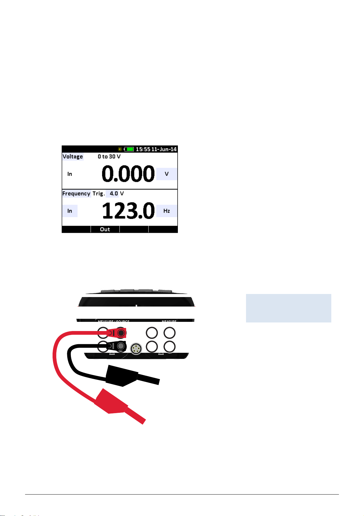
6.3 Sourcing Voltage
y
To source voltage, follow the principle of navigating through the functions described in
the guidelines in section 4.2 and proceed as follows:
1. Select “Voltage” from the Lower Mode list.
2. Select “0 to 20 V” from the Range list.
3. Select “Out” from the Test Mode list.
4. Connect leads to the voltage source terminals, as shown in Figure 9.
5. Enter the desired voltage using either the ARROW keys or the numeric keys.
-
+
UUT
Figure 9
Connections for Sourcing
Voltage and Frequenc
128797 03 2015-04-22 30
Page 32

6.4 Sourcing Frequency
To source a signal, follow the principle of navigating through the functions described in
the guidelines in section 4.2 and proceed as follows:
1. Select “Frequency” from the Lower Mode list.
1. Select “Out” from the Test Mode list.
2. Select the desired frequency unit from the Units list.
3. Connect leads to the frequency output terminals, as shown in Figure 9.
4. Enter the desired frequency using either the ARROW keys or the numeric keys.
5. The amplitude can be changed by entering the Output Volt peak to peak (Out. Vpp)
setup field. Use either the ARROW keys or the numeric keys to change the
amplitude.
6.5 Sourcing a Pulse Train
The ASC-400 calibrator can generate a pulse train with a selectable number of pulses
at a desired frequency and output level.
For example, setting the frequency to 10Hz and the number of pulses to 99999 would
produce 99999 pulses for a period of 10 seconds.
To source a pulse, use the same connection as for frequency, and follow the principle of
navigating through the functions described in the guidelines in section 4.2 and proceed
as follows:
1. Select “Pulse” from the Lower Mode list.
2. Select the desired frequency unit from the Units list.
3. The amplitude of the pulse can be changed by entering the Output (Out. Vpp) setup
field. Use either the ARROW keys or the numeric keys to change the amplitude.
4. Enter the desired number of pulses (Count) using either the ARROW keys or the
numeric keys.
5. Press (Start) to start and stop the signal.
F4
128797 03 2015-04-22 31
Page 33

6.6 Sourcing mV
To source an mV, follow the principle of navigating through the functions described in
the guidelines in section 4.2 and proceed as follows:
1. Connect the thermocouple leads to the appropriate polarized TC mini plug, and
insert the plug into the TC terminals on the calibrator, as shown in Figure 10.
2. Select “Voltage” from the Lower Mode list.
3. Select “-10 to 75 mV” from the Range list.
4. Select “Out” from the Test Mode list.
5. Enter the desired mV using either the ARROW keys or the numeric keys.
Note…
CJ compensation is not active in this mode.
128797 03 2015-04-22 32
Page 34

6.7 Sourcing Thermocouples
To source a thermocouple, follow the principle of navigating through the functions
described in the guidelines in section 4.2 and proceed as follows:
1. Connect the thermocouple leads to the appropriate polarized TC mini plug, and
insert the plug into the TC terminals on the calibrator, as shown in Figure 10.
2. Select “Thermocouple” from the Lower Mode list.
3. Select the desired thermocouple type from the TC Type list.
4. Select the desired CJ mode from the CJ Mode list.
If CJ Manual is selected, enter CJ temperature.
5. Select the desired temperature unit from the Units list.
6. Select “Out” from the Test Mode list.
7. Enter the temperature using either the ARROW keys or the numeric keys.
Note…
The TC wire and connector used must match the TTX / signal converter input
Figure 10
Connections for Thermocouple
temperature and mV output.
(showing additional mA loop from
TTX / signal converter)
128797 03 2015-04-22 33
Page 35

6.8 Sourcing Ohms/RTDs
To source an RTD, follow the principle of navigating through the functions described in
the guidelines in section 4.2 and proceed as follows:
1. Select “RTD” or “Resistance” from the Lower Mode list.
2. Select the desired RTD type from the RTD Type list (only when selecting “RTD” from
the Lower Mode list).
3. Select the desired temperature unit from the Units list (only when selecting “RTD”
from the Lower Mode list).
4. Select “Out” from the Test Mode list.
5. Connect the calibrator to the instrument being tested, as shown in Figure 11.
6. Enter the temperature or the resistance using either the ARROW keys or the
numeric keys.
Note…
The ASC-400 calibrator simulates a 2-wire RTD. To connect 3- or 4-wire
transmitter, use stacked test leads, as shown in Figure 12.
Figure 11
Connections for Outputting RTDs
(always 2-wire)
(showing additional mA loop
from TTX / signal converter)
128797 03 2015-04-22 34
Page 36

3-wire connection 4-wire connection
Figure 12
Using a 3- or 4-wire
Connection for RTDs
6.9 Custom RTD
The ASC-400 offers the possibility of entering a custom curve-fit PRT into the calibrator for
sourcing and measuring.
Follow the principle of navigating through the functions described in the guidelines in
section 4.2 and proceed as follows:
1. Select “Custom” from the RTD Type list. The option is found at the bottom of the list.
2. Press (System) to access the System Settings.
F3
3. Enter the desired values in the Custom RTD setting fields using either the ARROW
keys or the numeric keys and accept the values.
4. Leave the System Settings setup.
5. Attach the custom RTD leads as shown in Figures 11 or 12.
The custom function uses the Calendar-Van Dusen equation for outputting and
measuring custom RTDs.
128797 03 2015-04-22 35
Page 37

The coefficient C is only used for temperatures below 0°C. Only A and B coefficients are
needed for the range above 0°C, so coefficient C should be set to 0.
The R0 is the resistance of the probe at 0°C.
The ITS 90 coeffici ents for PT385, PT3926, and PT3616 are shown in Table 1.
Table 1
RTD Coefficients
RTD Range (°C) R0 Coefficient A Coefficient B Coefficient C
PT385
PT385
PT3926
PT3926
PT3916
PT3916
-200 to 0 100 3.9083 x 10⁻³ -5.775 x 10⁻⁷ -4.183 x 10⁻¹²
0 to 850 100 3.9083 x 10⁻³ -5.775 x 10⁻⁷ Below 0 100 3.9848 x 10⁻³ -5.87 x 10⁻⁷ -4 x 10-12
Above 0 100 3.9848 x 10⁻³ -5.87 x 10⁻⁷ Below 0 100 3.9692 x 10⁻³ -5.8495 x 10⁻⁷ -4.2325 x 10⁻¹²
Above 0 100 3.9692 x 10⁻³ -5.8495 x 10⁻⁷ -
6.10 Using Auto Output functions
The ASC-400 calibrator has two Auto Output functions:
Step
Ramp
6.10.1 Using the Step function
To use the Step function, follow the principle of navigating through the functions
described in the guidelines in section 4.2 and proceed as follows:
1. Select the desired lower mode from the Lower Mode list. Auto Output options are
not available for Pulse, Pressure and Baro modes.
2. Select “Out Step” from the Test Mode list.
128797 03 2015-04-22 36
Page 38

3. If TC or RTD is selected, choose the type and temperature units first, to get proper
step values.
F3
4. Selection of Step is also possible using the function key (Step) for quick,
menu free access.
5. Select the desired step size from the Step Size list. The ASC-400 will step from the
0% set source value to the 100% set source value in 10%, 20% or 25%increments.
The step time is adjustable from 1 to 999 seconds.
6. Exit the edit mode menu when all the selections have been made.
F3
7. Press (Step) to access the MANUAL Step menu.
or
F4
8. Press (Auto) to start auto stepping, using the selected step time.
F2
9. Pres either (–Step) or (+Step) to Step up- or downwards.
F4
10. In AUTO step, press (Stop) to stop the auto stepping.
11. To cancel Step or Auto step mode, press (Back).
6.10.2 Using the Ramp function
F3
F1
To use the Ra mp function, follow the principle of navigating through the functions
described in the guidelines in section 4.2 and proceed as follows:
1. Select the desired lower mode from the Lower Mode list. Auto Output options are
not available for Pulse, Pressure and Baro modes.
2. Select “Out Ramp” from the Test Mode list.
128797 03 2015-04-22 37
Page 39

3. If TC or RTD is selected, choose the type and temperature units first, to get proper
ramp values.
F4
4. Selection of Ramp is also possible using the function key (Ramp) for quick,
menu free access.
5. Select the desired 0% and 100% values. The ASC-400 will ramp from the 0% set
source value to the 100% set source value in the selected time (5 to 999 seconds).
6. Exit the edit mode menu when all the selections have been made.
7. Press (Start) to begin auto rapping.
F4
8. When ramping, press (Stop) to stop ramping.
F4
F1
9. To cancel Ramp mode, press (Back).
128797 03 2015-04-22 38
Page 40

7.0 Using Isolated Measure Modes (Upper Display)
7.1 Measuring mA (external loop supply)
The current output of a transmitter, or any other 0 to 24 mA current, can be measured
using the upper display.
To make the desired measurements, follow the principle of navigating through the
functions described in the guidelines in section 4.2 and proceed as follows:
1. Select “Current” from the Upper Mode list.
2. Select the primary parameters to be measured and accept the selections.
3. Connect the leads to the isolated inputs of the calibrator, as shown in Figure 13.
Figure 13
mA current measurement
connection (upper window)
128797 03 2015-04-22 39
Page 41

7.2 Measuring current with internal loop power
To test/calibrate a 2-wire, loop powered transmitter, as stand alone, use the loop power
function. This function activates a 24V supply in series with the current measuring
circuit. To use this option, follow the principle of navigating through the functions
described in the guidelines in section 4.2 and proceed as follows:
1. Select “Current” from the Upper Mode list.
2. Select “24V On” from the 24V Power list.
3. Connect the ASC-400 calibrator to transmitter current loop terminals, as shown in
Figure 14.
Figure 14
Connection using build in
loop supply in ASC-400
128797 03 2015-04-22 40
Page 42

7.3 Measuring Voltage
The voltage output of a transmitter can be measured using the upper display.
To make the desired measurements, follow the principle of navigating through the
functions described in the guidelines in section 4.2 and proceed as follows:
1. Select “Voltage” from the Upper Mode list.
2. Select the primary parameters to be measured and accept the selections.
3. Connect the leads to the isolated inputs of the calibrator, as shown in Figure 13.
7.4 Measuring Pressure
Warning
To avoid a violent release of pressure in a pressurized system, shut off the valve and
slowly bleed off the pressure before you attach the pressure module to the pressure
line.
Caution…
To avoid damaging the pressure module from overpressure, never apply pressure
above the rated maximum printed on the module.
To avoid damaging the pressure module from corrosion, use it only with specified
materials. Refer to the pressure module documentation for material compatibility.
To measure pressure, follow the principle of navigating through the functions described
in the guidelines in section 4.2 and proceed as follows:
1. Connect the pressure module (JOFRA APM) to the ASC-400 calibrator, as shown in
Figure 15.
The calibrator can measure pressure on both the upper and the lower display. This
makes it possible to display the pressure value in two different pressure units at the
same time.
2. Select either the upper or lower display to work from.
3. Select “Pressure” from the Upper or Lower Mode list.
4. Select the desired measuring unit from the Units list
128797 03 2015-04-22 41
Page 43

5. Zero the pressure module (see section 5.5.1 for using the zeroing function).
Figure 15
Measuring on a Pressure
Transmitter (PTX)
Pressure transmitter
APM pressure module
128797 03 2015-04-22 42
Page 44

8.0 Using the Upper and Lower Display for Calibration and Testing
8.1 Performing a Temperature Switch Test
The ASC-400 calibrator can detect switch state changes and link the results in any
source/simulate mode (except pulse), performing an automatic or semi automatic switch
calibration, on a great variety of pressure, temperature and electrical level switches.
An example is given below for calibrating a temperature switch, measuring the
temperature with an external RTD sensor, using an external temperature source.
RTD Probe
Temperature
Switch
To perform a switch test, follow the principle of navigating through the functions
described in the guidelines in section 4.2 and proceed as follows:
1. Select the upper display and select “Switch Test” from the Upper Mode list.
2. Connect the ASC-400 calibrator to the switch using the switch terminals. The polarity
of the terminals does not matter.
3. The upper display shows no read outs at neither “Closed”, “Opened” nor “Dead
band”
Figure 16
Temperature Switch Test
128797 03 2015-04-22 43
Page 45

4. Raise the temperature slowly until the switch opens.
5. Lower the temperature slowly until the switch closes.
6. The upper display will now show :
the temperature when the switch closed
the temperature that the switch opened at
the dead band between the temperatures readings.
7. To perform another test clear the data by selecting “Reset” using the edit mode.
128797 03 2015-04-22 44
Page 46

8.2 Performing a Pressure Switch Test
The ASC-400 calibrator can detect contact state changes and capture the results in any
source/simulate mode (except pulse). The calibrator records switch state and pressure
measurement, at the time of switch change, after the test, the result is displayed in a
convenient and easy to use format.
An example is given below for a pressure switch test.
Pressure Switch
To perform a switch test, follow the principle of navigating through the functions
described in the guidelines in section 4.2 and proceed as follows:
1. Select the upper display and select “Switch Test” from the Upper Mode list.
2. Connect the ASC-400 calibrator to the switch using the pressure switch terminals.
The polarity of the terminals does not matter.
Hand Pump
Figure 17
Pressure Switch Test
APM Module
128797 03 2015-04-22 45
Page 47

3. Connect the pump to the ASC-400 calibrator and the pressure switch.
4. Make sure the vent on the pump is open. Zero the pump if necessary.
Note…
Zero the APM if necessary. Close the vent after zeroing the calibrator.
5. The upper display shows no read outs at neither “Closed”, “Opened” nor “Dead
band”
6. Apply pressure with the pump slowly until the switch opens.
Note…
In the switch test mode the display update rate is increased to help capture
changing pressure inputs. Even with this enhanced sample rate pressurizing
device under test should be done slowly to ensure accurate readings.
7. Vent the pump slowly until the pressure switch closes.
8. The upper display will now show :
the pressure when the switch closed
the pressure that the switch opened at
the dead band between the pressure readings.
128797 03 2015-04-22 46
Page 48

8.3 Testing an Input or Indicating Device
To test and calibrate actuators, recording, and indicating devices using the source
functions, follow the principle of navigating through the functions described in the
guidelines in section 4.2 and proceed as follows:
1. Select the lower display and select the desired primary parameter from the Lower
Mode list.
2. Select “Out” from the Test Mode list (input/output control).
3. Connect the leads to the device and the ASC-400 calibrator as shown in Figure 18.
Figure 18
Connections for Testing an
Output Device
Input / Measure Device
8.4 Calibrating an I/P Device
To calibrate a device that controls pressure, follow the principle of navigating through
the functions described in the guidelines in section 4.2 and proceed as follows:
1. Select the upper display and select “Pressure” from the Upper Mode list.
2. Select the lower display and select “Current” from the Lower Mode list.
3. Connect the ASC-400 calibrator to the device as shown in Figure 19.
The calibrator will simulate the transmitter current and measure the output pressure.
4. Enter a current using either the ARROW keys or the numeric keys.
3 mA max. current
128797 03 2015-04-22 47
Page 49

Figure 19
Calibrating an I/P Device
Pressure Device
APM pressure module
128797 03 2015-04-22 48
Page 50

8.5 Calibrating a Transmitter (Signal Converter)
To calibrate a transmitter both the upper and the lower displays will be used; one for
measuring the output, and one for sourcing the input. This section covers all but the
pressure transmitters. A RTD temperature transmitter is used in this example.
Follow the principle of navigating through the functions described in the guidelines in
section 4.2 and proceed as follows:
1. Select the lower display and select “RTD” from the Lower Mode list.
2. Select “Out” from the Test Mode list (input/output control).
3. Select “RTD” from the RTD Type list.
4. Select the upper display and select “Current” from the Upper Mode list.
5. Select “4 to 20mA” from the Range list.
6. To turn the loop power on, select “24V On” from the 24V Power list (loop power).
7. Connect the ASC-400 calibrator to the transmitter as shown in Figure 20.
8. Enter output values using the numeric keys or fine adjust using the ARROW keys.
9. Adjust the transmitter as necessary.
To calibrate different transmitter types, follow the above steps with the exception of
selecting the appropriate input type on the lower display.
Figure 20
Calibrating a Transmitter
128797 03 2015-04-22 49
Page 51

8.6 Calibrating a Pressure Transmitter (loop powered 4-20 mA)
To calibrate a pressure transmitter both the upper and the lower displays will be used;
upper for measuring the output, and lower for pressure measurement.
Follow the principle of navigating through the functions described in the guidelines in
section 4.2 and proceed as follows:
1. Select the lower display and select “Pressure” from the Lower Mode list.
2. Select the upper display and select “Current” from the Upper Mode list.
3. Select “4 to 20mA” from the Range list.
4. To turn the loop power on, select “24V On” from the 24V Power list.
5. Connect the ASC-400 calibrator to the transmitter and the pressure module as
shown in Figure 21.
6. Zero the pressure module.
7. Test the transmitter at 3 or more points of the span to prove hysteresis.
8. Adjust the transmitter as necessary.
128797 03 2015-04-22 50
Page 52

Figure 21
Calibrating a Pressure
Transmitter
APM pressure module
Hand pump
128797 03 2015-04-22 51
Page 53

8.7 Using Scaled Current or Voltage when testing or calibrating a T/I Transmitter
The ASC-400 calibrator has the ability to read current or voltage on the upper display
that is scaled to and displayed in the same units of the lower display.
Follow the principle of navigating through the functions described in the guidelines in
section 4.2 and proceed as follows:
1. Select the lower display and select “RTD” from the Lower Mode list.
2. Select “Out step” from the Test Mode list (input/output control).
3. Select “RTD” from the RTD Type list.
4. Set the 0%, the 100% span points and the time using either the ARROW keys or the
numeric keys
5. Select the upper display and select either “Current” or “Voltage” from the Upper
Mode list.
6. Select power mode, internal or external power. (Current only)
7. Select “Scaling” from the Units list.
8. From the Scaling Menu set the 0% and 100% point for the upper and lower displays
using either the ARROW keys or the numeric keys.
128797 03 2015-04-22 52
Page 54

8.8 Using Percent Error when testing or calibrating a T/I Transmitter
The ASC-400 calibrator features a function which can calculate signal or pressure vs.
milliamp error as a percentage of the 4 to 20 mA loop span.
Follow the principle of navigating through the functions described in the guidelines in
section 4.2 and proceed as follows:
1. Select the lower display and select “RTD” from the Lower Mode list.
2. Select “Out step” from the Test Mode list (input/output control).
3. Select “RTD” from the RTD Type list.
4. Set the 0%, the 100% span points and the time using either the ARROW keys or the
numeric keys
5. Select the upper display and select either “Current” or “Voltage” from the Upper
Mode list.
6. Select power mode, internal or external power. (Current only)
7. Select “%Error” from the Units list.
8. From the %Error Menu set the 0% and 100% point for the upper and lower displays
using either the ARROW keys or the numeric keys.
128797 03 2015-04-22 53
Page 55

9.0 Maintenance
Only qualified service personnel should perform calibration, repairs, or service not covered by
this manual.
For maintenance procedures not described in this manual, or if the ASC-400 calibrator needs
repair, please contact AMETEK Denmark Service Department as described below in section 9.1
“Returning the calibrator to service”.
9.1 Returning the calibrator to service
If the calibrator continuously malfunctions, verify that the instrument is being operated as
described in this manual and return it to the manufacturer for repair/service.
If the calibrator needs repair and is under warranty, see the warranty statement section 1.1 for
terms. If the warranty has lapsed, the calibrator can be repaired and returned for a fixed fee.
When returning the instrument please enclose a fully completed service information form.
Simply copy the “Service info” form from the following page and fill in the required information.
The calibrator should be returned in the original packing.
Warning
To avoid possible electric shock, personal injury or sudden release of pressure, review
“Safety Instructions” Section 2.0 before proceeding.
Note…
AMETEK Denmark’s liability ceases if:
parts are replaced/repaired using spare parts, which are not identical to those
recommended by the manufacturer.
non-original parts are used in any way when operating the instrument.
AMETEK Denmark’s liability is restricted to errors originated from the factory.
128797 03 2015-04-22 54
Page 56

Service info
Customer data: Date:
Customer name and address:__________________________ _________________________________________
Attention and dept.:_______________________________________ ____________________________________
Fax no./phone no.:____________________________________________________________________________
Your order no.:_______________________________________________________________________________
Delivery address:_____________________________________________________________________________
Distributor name:__________________________________________________________________________ ____
Instrument data:
Model and serial no.:___________________________________________________________________________
Warranty claimed Yes:___________ No:___________ Original invoice no.:________________________
_____________________________________________________________________________________________________
Temp. Sensor Service request: This instrument is sent for
calibration input (please check off):
___ Calibration as left ___ Check
___ Calibration as found and as left ___ Service
___ Accredited calibration as left ___ Repair
___ Accredited calibration as found and as left.
_____________________________________________________________________________________________________
Diagnosis data/cause for return:
Diagnosis/fault description:______________________________________________________________________
_____________________________________________________________________________________________________
_____________________________________________________________________________________________________
_____________________________________________________________________________________________________
_____________________________________________________________________________________________________
Special requests:__________________________________ _______ ____ ____ _______ ____ _______ ____ ______
_____________________________________________________________________________________________________
_____________________________________________________________________________________________________
_____________________________________________________________________________________________________
_____________________________________________________________________________________________________
Safety precautions: if the product has been exposed to any hazardous substances, it must be
thoroughly decontaminated before it is returned to AMETEK Denmark A/S. Details of the hazardous
substances and any precautions to be taken must be enclosed.
128797 03 2015-04-22 55
Page 57

9.2 Replacing batteries
The battery icon indicates how much power is remaining.
If the batteries discharge too deeply the calibrator will automatically shut down to avoid battery
leakage and false measurements.
All stored data will be preserved.
Caution…
Always set the charger switch in “Alkaline” position when alkaline batteries are installed
The ASC-400 calibrator uses six AA batteries.
Use ONLY AA size Alkaline batteries or optional NiMH rechargeable batteries.
Ensure the battery type switch is in the right position (Alkaline or rechargeable).
(factory setting).
1. Unscrew the captive screw to gain access to the battery compartment.
Figure 22
Replacing batteries
2. Replace the batteries taking care to note polarity for their proper installation.
Position for
Alkaline
batteries
Position for
Rechargeable
batteries
3. Remount battery cover and the captive screw.
128797 03 2015-04-22 56
Page 58

9.3 Storing
It is not necessary to store away the ASC-400 calibrator after use.
The calibrator can be part of a continuous set-up, as long as it is kept in a dry, clean place.
Alternatively the calibrator can be stored in the soft bag delivered with the instrument.
9.4 Cleaning
Caution…
Before cleaning the calibrator, you must switch it off.
Periodically wipe the case of the calibrator with a damp soft cloth. A mild detergent can be used
with the water.
Caution…
The soft cloth must be firmly wrung to avoid any water penetrating the calibrator
and causing damage.
Do not use solvents or abrasive cleansers. They might damage the display and
case.
128797 03 2015-04-22 57
Page 59

10.0 Errors
If the power is lost to the entire test set-up or part of it, it is highly recommended to restart the
calibration.
GENERAL ERRORS
Error description Solution
Warning
During set-up, make sure that there is correlation between the software set-up, and the
actual distribution of the sensors connected to the calibrator. The software cannot
detect misplacements of sensors.
ASC-400 does not turn on :
Faulty readout :
No contact with the ASC-400 :
When using Hyper Terminal or similar terminal programs, and co mmunications
Faulty readout from
thermocouples:
Check the batteries
Check the power supply
If the error still occurs, return the ASC-400 to the manufacturer for service
Check that the connected sensors are correctly connected and that they are
properly polarised
Check that the ASC-400 is set up correctly
Switch the ASC-400 off and on again
If the error still occurs, return the ASC-400 to the manufacturer for service
Check the power supply
Check the USB connection. Use only the supplied cable
Switch the ASC-400 off and on again - and set up the software again
If the error still occurs, return the ASC-400 to the manufacturer for service
fails, check that the program has been set up correctly.
Check that the correct type has been selected during setup
Check that the sensors have been correctly polarised and connected
Check that the correct type of cold junction has been selected
manually/automatically/off
Check that the ASC-400 is not subjected to direct or indirect heat sources
128797 03 2015-04-22 58
Page 60

11.0 Technical specifications
g
play
(
)
All specifications are given with an ambient temperature of 23 ±5°C / 73 ±9°F
Mechanical specifications
Description Value
Operating temperature :
Storage temperature :
Dimension LxWxH :
Case protection:
Humidity:
Display:
Weight incl. Batteries :
Unit in soft case :
Weight incl. Test leas and test chips :
Shipping size :
Shipping weight :
-10 to 50°C / 14 to 122°F
-20 to 60°C / -4 to 140°F
220x96x55 mm / 8.66x3.78x2.17 in
IP40
0% to 80% R.H. non-condensin
2.8" 320*240 TFT colour dis
584 g / 20.6 oz
235x95x115 mm / 9.25x3.74x4.53 in
933 g / 32.91 oz
275x100x175 mm / 10.83x3.94x6.89 in
1233 g /43.49 oz
Electrical specifications
Description Value
Mains adapter:
Batteries :
Battery lifetime, Alkaline, backlight low:
Battery lifetime, Alkaline, backlight high,
12 mA: loop power:
attery charge current. Use only NiMH cells
ith capacity larger than 1700 mAh.:
(opt i o n) 9VDC/500mA - 230VAC/115VAC
6 x AA batteries
1.5V AA… Alkaline (non rechargeable) or AA NiMh
rechargeable
30 hours
13 hours
85 mA
RS232 communication interface :
Connector :
Communication type :
Display update rate:
Temperature coefficient:
-10°C to 18°C and 28°C to 50°C:
Thermocouple mV
TC mV read
TC mV source
Maximum output current is 3 mA Output impedance 0.010 ohm. Input impedance 10 Mohm.
128797 03 2015-04-22 59
Mini USB female (B)
USB 2.0 / ASCII
2.5/second (mA, V, resistance, RTD, TC)
10/second (pressure, switch-test)
0.003%FS/°C / 0.0017%FS/°F (mA, V, resistance)
0.001%rdg/°C / 0.0006%rdg/°F (frequency)
Range Accuracy ±
Min Max 12 months
-10.000 mV 75.000 mV 0.015% rdg +10µV
-10.000 mV 75.000 mV 0.015% rdg +10µV
Page 61

Thermocouple Cold junction
Range Accuracy ±
Min Max 12 months
CJC compensation
CJC outside above
Volt V
Read (Isolated)
Read (non-isolated)
Source
18°C / 64°F 28°C / 83°F 0.2°C / 0.36°F
0.05°C/°C
0.05°F/°F
Range Accuracy ±
Min Max 12 months
0.000 V 30.000 V 0.01% rdg +2mV
0.000 V 20.000 V 0.01% rdg +2mV
0.000 V 20.000 V 0.01% rdg +2mV
Maximum output current in voltage ranges is 3 mA Output impedance <1 ohm . Input resistance 1 Mohm.
Frequency Pulse
CPM read
Hz read
0.050 10.000 0.05% rdg + 0.001Hz
10.000 100.00 0.05% rdg + 0.01Hz
100.00 1000.0 0.05% rdg + 0.1Hz
1000.0 10000 0.05% rdg + 1Hz
Range Accuracy ±
Min Max 12 months
2.0 600.0 0.05% rdg + 0.1CPM
KHz read
CPM source
Hz source
KHz source
Pulse (source only)
Rate : 1 Hz to 10KHz
1.000 10.000 0.05% rdg +0.001KHz
2.0 600.0 0.05% rdg
0.050 1000.0 0.05% rdg
1000.0 10000 0.06% rdg
1.000 10.000 0.06% rdg
1 99999
Input voltage amplitude range on frequency is 1 to 20 V, Trigger level 0.2 to 10 volt. Minimum pulse width 10 µS.
Output amplitude is adjustable from 1 to 20 V and is a square wave with a 50% duty cycle.
For output frequency, a slight negative offset of approximately -0.1 V is present to assure zero crossing.
Ohm
Ohm read (low)
Ohm read (high)
Ohm source (low)
@ 0.1 to 0.2 mA
@ 0.2 to 0.5 mA
@ 0.5 to IE max
Range Accuracy ±
Min Max 12 months
0.00 400.00 0.015% rdg + 0.03 ohm
400.0 4000.0 0.015% rdg + 0.3 ohm
5.0
5.0
5.0
400.00
400.00
400.00
0.015% rdg +0.10 ohm
0.015% rdg +0.05 ohm
0.015% rdg +0.03 ohm
Ohm source (high)
@ 0.05 to 0.1 mA
@ 0.1 to IE max
400.0
400.0
4000.0
4000.0
0.015% rdg +0.5 ohm
0.015% rdg +0.3 ohm
True Ohm Measurement current (pulsed) 0.25 mA.
3W measurement current match 1% Source exitation current IEXI(max) = 2.0 V / R, IEXI must never exceed 3 mA.
Pulsed current (source) Unit is compatible with smart transmitters and PLCs with pulse > 5 ms.
128797 03 2015-04-22 60
Page 62

Current – mA and loop
Description Value
Range mA:
Loop power for transmitter:
Isolated input:
Current mA
Read (Isolated)
Read (non-isolated)
Source
Hart resistor 250 ohm (On/Off in software). Maximum loop resistance source @ 24 mA (Hart on/ Hart off) 6 50 ohm
/ 900 ohm.
mA source voltage input range (external power/HART resistor off) 1V ‐ 30V.
0 to 24 mA
Yes, 24 VDC / ±10%
Yes
Range Accuracy ±
Min Max 12 months
0.000 mA 24.000 mA 0.010% rdg +2
0.000 mA 24.000 mA 0.010% rdg +2µA
0.000 mA 24.000 mA 0.010% rdg +2
µ
A
µ
A
128797 03 2015-04-22 61
Page 63

Thermocouple - TC
Description Value
TC types:
Cold junction compensation ON/OFF
Control:
TC Type
B
BP
C
E
J
K
L
N
R
S
T
128797 03 2015-04-22 62
Temperature
resolution
Source Measure
0,1 0,1
0,1 0,1
0,1 0,1
0,1 0,01
0,1 0,01
0,1 0,01
0,1 0,01
0,1 0,01
0,1 0,1
0,1 0,1
0,1 0,01
B, BP, C, E, J, K, L, N, R, S, T, U, XK
Yes
Temperature range 12 month accuracy
°C °F °C °F
Min. Max. Min. Max.
250 300 482 572 4,02 7,24
300 400 572 752 3,36 6,05
400 600 752 1112 2,47 4,45
600 800 1112 1472 1,60 2,88
800 1000 1472 1832 1,39 2,51
1000 1820 1832 3308 1,07 1,93
0 1200 32 2192 0,89 1,61
1200 2000 2192 3632 1,39 2,51
2000 2500 3632 4532 1,96 3,53
0 200 32 392 0,75 1,35
200 800 392 1472 0,64 1,16
800 1200 1472 2192 0,78 1,41
1200 1600 2192 2912 0,97 1,75
1600 2000 2912 3632 1,24 2,24
2000 2316 3632 4200,8 1,70 3,06
-200 -100 -328 -148 0,46 0,83
-100 0 -148 32 0,26 0,47
0 400 32 752 0,20 0,36
400 1000 752 1832 0,30 0,54
-210 -150 -346 -238 0,59 1,07
-150 0 -238 32 0,34 0,62
0 660 32 1220 0,26 0,47
660 1200 1220 2192 0,36 0,65
-200 -100 -328 -148 0,72 1,30
-100 0 -148 32 0,35 0,63
0 400 32 752 0,30 0,54
400 800 752 1472 0,37 0,67
800 1000 1472 1832 0,42 0,76
1000 1372 1832 2501,6 0,53 0,96
-200 -100 -328 -148 0,37 0,67
-100 900 -148 1652 0,26 0,47
-200 -100 -328 -148 1,08 1,95
-100 0 -148 32 0,50 0,90
0 1000 32 1832 0,41 0,74
1000 1300 1832 2372 0,49 0,89
-50 0 -58 32 2,72 4,90
0 200 32 392 1,89 3,41
200 660 392 1220 1,17 2,11
660 1600 1220 2912 0,95 1,71
1600 1768,1 2912 3214,58 1,07 1,93
-50 0 -58 32 2,51 4,52
0 200 32 392 1,86 3,35
200 400 392 752 1,21 2,18
400 1600 752 2912 1,10 1,98
1600 1768,1 2912 3214,58 1,23 2,22
-200 -100 -328 -148 0,70 1,26
-100 0 -148 32 0,38 0,69
0 200 32 392 0,26 0,47
Page 64

200 400 392 752 0,22 0,40
U
XK
Does not include thermocouple wire error and CJC.
0,1 0,01
0,1 0,01
-200 0 -328 32 0,54 0,98
0 600 32 1112 0,26 0,47
-200 -100 -328 -148 0,43 0,78
-100 0 -148 32 0,23 0,42
0 400 32 752 0,18 0,33
400 800 752 1472 0,24 0,44
128797 03 2015-04-22 63
Page 65

Resistance - RTD
Description Value
RTD types:
Pt10/50/100/200/400/500/1000, Cu10/50/100, Ni120,
YSI400
Response time:
Connection:
4-wire RTD
Type
Pt10(90)385
Pt50(90)385
Pt100(90)385
Pt200(90)385
Pt400(90)385
Pt500(90)385
Pt1K(90)385
P50(90)391
P100(90)391
P100(90)392
M10(90)427
M50(90)428
M100(90)428
M100(90)617
Temperature
resolution
Source Measure
0,1 0,1
0,1 0,01
0,1 0,01
0,1 0,01
0,1 0,01
0,1 0,01
0,1 0,01
0,1 0,01
0,1 0,01
0,1 0,01
0,1 0,1
0,1 0,01
0,1 0,01
0,1 0,01
Less than 5 mSec
2, 3 and 4-wire
Temperature range 12 month accuracy
°C °F °C °F
Min. Max. Min. Max.
-200 100 -328 212 0,85 1,53
100 400 212 752 0,98 1,77
400 660 752 1220 1,12 2,02
660 850 1220 1562 1,23 2,22
-200 100 -328 212 0,22 0,4
100 400 212 752 0,29 0,53
400 660 752 1220 0,35 0,63
660 850 1220 1562 0,41 0,74
-200 100 -328 212 0,12 0,22
100 400 212 752 0,2 0,36
400 660 752 1220 0,26 0,47
660 850 1220 1562 0,31 0,56
-200 265 -328 509 0,14 0,26
265 400 509 752 0,55 0,99
400 660 752 1220 0,64 1,16
660 850 1220 1562 0,72 1,3
-200 0 -328 32 0,09 0,17
0 400 32 752 0,34 0,62
400 660 752 1220 0,41 0,74
660 850 1220 1562 0,47 0,85
-200 100 -328 212 0,22 0,4
100 400 212 752 0,29 0,53
400 660 752 1220 0,35 0,63
660 850 1220 1562 0,41 0,74
-200 100 -328 212 0,14 0,26
100 400 212 752 0,2 0,36
400 660 752 1220 0,26 0,47
660 850 1220 1562 0,31 0,56
-200 100 -328 212 0,21 0,38
100 400 212 752 0,28 0,51
400 660 752 1220 0,35 0,63
660 850 1220 1562 0,4 0,72
850 1100 1562 2012 0,49 0,89
-200 100 -328 212 0,15 0,27
100 400 212 752 0,2 0,36
400 660 752 1220 0,26 0,47
660 850 1220 1562 0,31 0,56
850 1100 1562 2012 1,38 2,49
-260 100 -436 212 0,13 0,24
100 400 212 752 0,19 0,35
400 630 752 1166 0,25 0,45
-200 260 -328 500 0,85 1,53
-200 200 -328 392 0,21 0,38
-200 200 -328 392 0,14 0,26
-60 180 -76 356 0,11 0,2
128797 03 2015-04-22 64
Page 66

H120(90)672
P100(90)JIS
YSI(90)400
0,1 0,01
0,1 0,01
0,1 0,01
-80 260 -112 500 0,1 0,18
-200 100 -328 212 0,14 0,26
100 500 212 932 0,22 0,4
15 150 59 302 0,02 0,04
Read accuracy is based on 4 wire input.
Source accuracy in terminals 2 wire source.
Pressure modules, Barometric option (BARO) and APM CPF
APM CPF Type
(s)
3 bar
300 kPa
30 psi
10 bar
1 MPa
100 psi
30 bar
3 MPa
300 psi
100 bar
10 MPa
300 psi
300bar
30 MPa
3 kpsi
700 bar
70 MPa
10 kpsi
1000 bar
100 MPa
15 kpsi
Gauge
Bar MPa psi
-1 3
-0.099 0.300
-14.5 30
-1 10
-0.099 1.0
-14.5 100
-1 30
-0.099 3.0
-14.5 300
0 100
0 10.0
0 1 000
0 300
0 30.0
0 3 000
0 700
0 70.0
0 10 000
0 1000
0 100.0
0 15 000
12 month
Accuracy ±
0 to 30 % range
0.0075% FS 0.025% RDG 0.06% FS
0.0075% FS 0.025% RDG 0.06% FS
0.0075% FS 0.025% RDG 0.06% FS
0.015% FS 0.05% RDG N/A
0.015% FS 0.05% RDG N/A
0.03% FS 0.1% RDG N/A
0.03% FS 0.1% RDG N/A
Absolut e pressure APM CPF with ASC-400 BARO option / 12 month Accuracy ±
3 bar APM CPF Accuracy
0.0138 to 1 barA 0.0008 barA 1.38 to 100 kPaA 0.08 kPaA 0.2 to 14.5 psiA 0.011 psiA
1 to 4 barA
10 bar APM CPF Accuracy
0.0138 to 1 barA 0.0008 barA
1 to 4 barA 0.001 barA 0.1 to 0.4 MPaA 0.0001 MPaA 14.5 to 44.5 psiA 0.011 psiA
4 barA to 11 barA 0.025% RDG 0.4 MPaA to 1.1 MP aA 0.025% RDG 44.5 to 114.5 psiA 0.025% RDG
30 bar APM CPF
0.014 to 1 barA 0.001 barA 0.0014 to 0.1 MPaA 0.001 MPaA 0.2 to 14.5 psiA 0.01 psiA
1 to 10 barA 0.003 barA 0.1 to 1.0 MPaA 0.003 MPaA 14.5 to 104.5 psiA 0.03 psiA
10 barA to 31 barA 0.025% RDG 1.0 MPaA to 3.1 MPaA 0.025% RDG 104.5 to 314.5 psiA 0.025% RDG
0.025% RDG +
0.0003 barA
Accuracy
±
±
±
300 kpA APM CPF Accuracy
100 to 400 kPaA 0.025%
RDG +
1 MPa APM CPF Accuracy
0.00138 to 0.1 MPaA
3 MPa APM CPF Accuracy
0.00008 MPaA 0.2 to 14.5 psiA 0.011 psiA
±
±
±
Specified temperature range -10 to 50°C / 14 to 122°F ( APM CPF & BARO op tion) Vacuum FS , 1 bar / 100 kPA
/ 14.5 psi. F.S. (full scale) is the numerical value of the positive pressure range. Accuracy includes hysteresis,
nonlinearity, repeatability and reference standard uncertainty, 1 Year typical longterm stability, operated
inside the rated temperature span and pressure range. Requiring frequently zeroing.
12 month
Accuracy ±
30 to 110% range
30 psi APM CPF Accuracy
14.5 to 44.5 psiA
100 psi APM CPF Accuracy
100 psi APM CPF Accuracy
12 month
Accuracy ±
Vacuum % FS
0.025% RDG
+ 0.003 psiA
±
±
±
128797 03 2015-04-22 65
Page 67

Additional specifications - directives observed
Standards Description
2004/108/EC : EMC Directive
EN61326‐1: 2012 : Electrical equipment for measurement, control and
laboratory use – EMC-requirements: Class B equipment.
Emmision :
CISPR 11, Class B
Immunity :
IEC 61000-4-2 ESD 4 kV contact / 8 kV air
IEC 61000-4-3 Electromagnetic field 3 V/m 80 MHz to 1 GHz
3 V/m 1.4 GHz to 2 GHz
1 V/m 2 GHz to 2.7 GHz
IEC 61000-4-3 Voltage dip 0% during half cycle
0% during 1 cycle
40% during 10/12 cycles
70% during 25/30 cycles
IEC 61000-4-11 Short interruptions 0% during 250/300 cycles
IEC 61000-4-4 Burst 1 kV
IEC 61000-4-5 Surge ½ kV
IEC 61000-3-6 Conducted RF 3V (150 kHz to 80 MHz)
128797 03 2015-04-22 66
Page 68

12.0 List of accessories
All parts listed in the list of accessories is available from the factory through our dealers.
Please contact your dealer for assistance if you require parts, which do not appear in the list.
List of accessories
Accessories Part no.
Large padded soft case 127415
Soft bag incl. strap 128848
6 x 1.5V AA Ni-MH rechargeable batteries 128859
External Power Supply/Charger 9VDC/200mA-230VAC/115VAC 124720
Thermocouple male plug type K - Yellow 120517
Thermocouple male plug type N - Orange 120514
Thermocouple male plug type T - Blue 120515
Thermocouple male plug type J - Black 120516
Thermocouple male plug type R/S – Green 120518
Thermocouple male plug type Cu-Cu - White 120519
Extension cable for type K – 5 meter 121983
Extension cable for type N – 5 meter 122523
Cable 2 m (6.6ft.) with LEMO/Banana connectors 65-PT100-LB-CABLE
APM Pressure Modules Contact your local dealer for
various options or visit our
website :
www.ametekcalibration.com
128797 03 2015-04-22 67
Page 69

AMETEK Test & Calibration Instruments
A business unit of AMETEK Measurement &
Calibration Technologies Division offering the
following industry leading brands for test and
calibration instrumentation.
JOFRA Calibration Instruments
Temperature Calibrators
Portable dry-block calibrators, precision
thermometers and liquid baths. Temperature
sensors for industrial and marine use.
Pressure Calibrators
Convenient electronic systems ranging from
-25 mbar to 1000 bar - fully temperature-
compensated for problem-free and accurate
field use.
Signal Instruments
Process signal measurement and simulation for
easy control loop calibration and measurement
tasks.
M&G Dead Weight Testers & Pumps
Pneumatic floating-ball or hydraulic piston dead
weight testers with accuracies to 0.015% of
reading. Pressure generators delivering up to
1,000 bar.
Crystal Pressure
Digital pressure gauges and calibrators that are
accurate, easy-to-use and reliable. Designed for
use in the harshest environments; most products
carry an IS, IP67 and DNV rating.
Lloyd Materials Testing
Materials testing machines and software that
guarantees expert materials testing solutions.
Also covering Texture Analysers to perform
rapid, general food testing and detailed texture
analysis on a diverse range of foods and
cosmetics.
United Kingdom
Tel +44 (0)1243 833 302
jofra@ametek.co.uk
France
Tel +33 (0)1 30 68 89 40
general.lloyd-instruments@ametek.fr
Germany
Tel +49 (0)2159 9136 510
info.mct-de@ametek.de
Denmark
Tel +45 4816 8000
jofra@ametek.com
Allows measurement and characterization of
moisture-sensitive PET polymers and polymer
The hand held force gauges and motorized
testers have earned their reputation for quality,
reliability and accuracy and they represent the
Hardness testers, durometers, optical systems
and software for data acquisition and analysis.
www.ametekcalibration.com
USA
Florida
Tel +1 (800) 527 9999
cal.info@ametek.com
California
Tel +1 (800) 444 1850
crystal@ametek.com
India
Tel +91 22 2836 4750
jofra@ametek.com
Information in this document is subject to change without notice. ©2014, by AMETEK, Inc., www.ametek.com. All rights reserved.
Singapore
Tel +65 6484 2388
jofra@ametek.com
China
Shanghai
Tel +86 21 5868 5111
Beijing
Tel +86 10 8526 2111
Guangzhou
Tel +86 20 8363 4768
jofra.sales@ametek.com.cn
Davenport Polymer Test Equipment
density.
Chatillon Force Measurement
de facto standard for force measurement.
Newage Hardness Testing
 Loading...