

Page 1

Internal Analog Programming
(APG) Interface
for XT/HPD Series
Programmable DC Power Supplies
Operation Manual
APG-XT
APG-HPD
TM-5A6H-01XN Rev B www.programmablepower.com
Page 2

Page 3

About AMETEK
AMETEK Programmable Power, Inc., a Division of AMETEK, Inc., is a global leader in the design
and manufacture of precision, programmable power supplies for R&D, test and measurement,
process control, power bus simulation and power conditioning applications across diverse
industrial segments. From bench top supplies to rack-mounted industrial power subsystems,
AMETEK Programmable Power is the proud manufacturer of Elgar, Sorensen, California
Instruments and Power Ten brand power supplies.
AMETEK, Inc. is a leading global manufacturer of electronic instruments and electromec hanical
devices with annualized sales of $2.5 billion. The Company has over 11,000 colleagues working
at more than 80 manufacturing facilities and more than 80 sales and service centers in the United
States and around the world.
Trademarks
AMETEK is a registered trademark of AMETEK, Inc.
Other trademarks, registered trademarks, and product names are the property of their respective
owners and are used herein for identification purposes only.
Notice of Copyright
Internal Analog Programming (APG) Interface for XT/HPD Series Programmable DC Power
Supplies Operation Manual
© 2007 AMETEK Programmable Power, Inc. All rights reserved.
Exclusion for Documentation
UNLESS SPECIFICALLY AGREED TO IN WRITING, AMETEK PROGRAMMABLE POWER, INC.
(“AMETEK”):
(a) MAKES NO WARRANTY AS TO THE ACCURACY, SUFFICIENCY OR SUITABILITY OF ANY
TECHNICAL OR OTHER INFORMATION PROVIDED IN ITS MANUALS OR OTHER
DOCUMENTATION.
(b) ASSUMES NO RESPONSIBILITY OR LIABILITY FOR LOSSES, DAMAGES, COSTS OR
EXPENSES, WHETHER SPECIAL, DIRECT, INDIRECT, CONSEQUENTIAL OR INCIDENTAL,
WHICH MIGHT ARISE OUT OF THE USE OF SUCH INFORMATION. THE USE OF ANY SUCH
INFORMATION WILL BE ENTIRELY AT THE USER’S RISK, AND
(c) REMINDS YOU THAT IF THIS MANUAL IS IN ANY LANGUAGE OTHER THAN ENGLISH,
ALTHOUGH STEPS HAVE BEEN TAKEN TO MAINTAIN THE ACCURACY OF TH E
TRANSLATION, THE ACCURACY CANNOT BE GUARANTEED. APPROVED AMETEK CONTENT
IS CONTAINED WITH THE ENGLISH LANGUAGE VERSION, WHICH IS POSTED AT
WWW.PROGRAMMABLEPOWER.COM.
Date and Revision
February 2009 Revision B
Part Number
TM-5A6H-01XN
Contact Information
Telephone: 800 733 5427 (toll free in North America)
858 450 0085 (direct)
Fax: 858 458 0267
Email: sales@programmablepower.com
service@programmablepower.com
Web: www.programmablepower.com
i
Page 4

This page intentionally left blank.
ii
Page 5
G
G
Important Safety Instructions
Before applying power to the system, verify that your product is configured properly for your
particular application.
WARNIN
WARNIN
Only qualified personnel who deal with attendant hazards in power supplies, are allowed to perform
installation and servicing.
Ensure that the AC power line ground is connected properly to the Power Rack input connector or
chassis. Similarly, other power ground lines including those to application and maintenance
equipment must be grounded properly for both personnel and equipment safety.
Always ensure that facility AC input power is de-energized prior to connecting or disconnecting any
cable.
In normal operation, the operator does not have access to hazardous voltages within the chassis.
However, depending on the user’s application configuration, HIGH VOLTAGES HAZARDOUS TO
HUMAN SAFETY may be normally generated on the output terminals. The customer/user must
ensure that the output power lines are labeled properly as to the safety hazards and that any
inadvertent contact with hazardous voltages is eliminated.
Guard against risks of electrical shock during open cover checks by not touching any portion of the
electrical circuits. Even when power is off, capacitors may retain an electrical charge. Use safety
glasses during open cover checks to avoid personal injury by any sudden component failure.
Neither AMETEK Programmable Power Inc., San Diego, California, USA, nor any of the subsidiary
sales organizations can accept any responsibility for personnel, material or inconsequential injury,
loss or damage that results from improper use of the equipment and accessories.
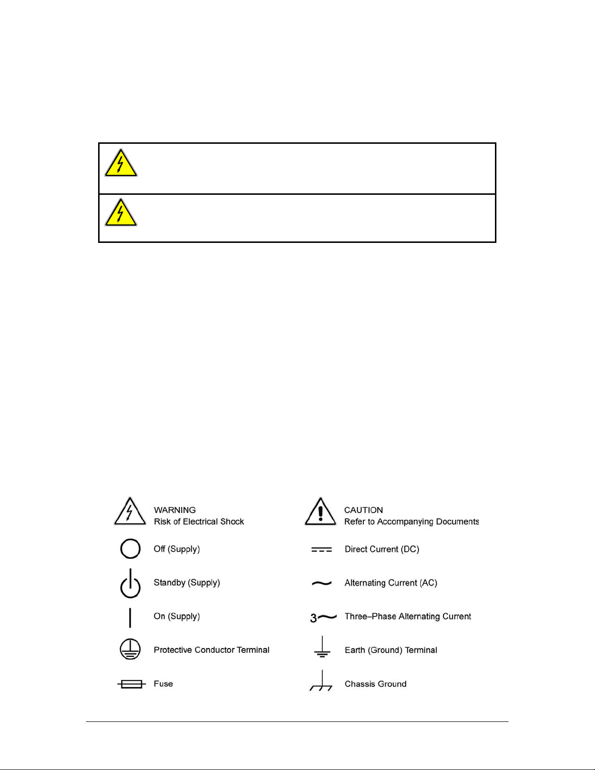
Hazardous voltages may be present when covers are removed. Qualified
personnel must use extreme caution when servicing this equipment.
Circuit boards, test points, and output voltages also may be floating above
(below) chassis ground.
The equipment used contains ESD sensitive parts. When installing
equipment, follow ESD Safety Procedures. Electrostatic discharges might
cause damage to the equipment.
SAFETY SYMBOLS
iii
Page 6

This page intentionally left blank.
iv
Page 7

Product Family: Internal Analog Programming (APG) Interface for XT/HPD
Series
Warranty Period: Five Years
WARRANTY TERMS
AMETEK Programmable Power, Inc. (“AMETEK”), provides this written warranty covering the
Product stated above, and if the Buyer discovers and notifies AMETEK in writing of any defect in
material or workmanship within the applicable warranty period stated above, then AMETEK may,
at its option: repair or replace the Product; or issue a credit note for the defective Product; or
provide the Buyer with replacement parts for the Product.
The Buyer will, at its expense, return the defective Product or parts thereof to AMETEK in
accordance with the return procedure specified below. AMETEK will, at its expense, deliver the
repaired or replaced Product or parts to the Buyer. Any warranty of AMETEK will not apply if the
Buyer is in default under the Purchase Order Agreement or where the Product or any part
thereof:
• is damaged by misuse, accident, negligence or failure to maintain the same as
specified or required by AMETEK;
• is damaged by modifications, alterations or attachments thereto which are not
authorized by AMETEK;
• is installed or operated contrary to the instructions of AMETEK;
• is opened, modified or disassembled in any way without AMETEK’s consent; or
• is used in combination with items, articles or materials not authorized by AMETEK.
The Buyer may not assert any claim that the Products are not in conformity with any warranty
until the Buyer has made all payments to AMETEK provided for in the Purchase Order Agreement.
PRODUCT RETURN PROCEDURE
1. Request a Return Material Authorization (RMA) number from the repair facility (must be
done in the country in which it was purchased):
• In the USA, contact the AMETEK Repair Department prior to the return of the
product to AMETEK for repair:
Telephone: 800-733-5427, ext. 2295 or ext. 2463 (toll free North America)
858-450-0085, ext. 2295 or ext. 2463 (direct)
• Outside the United States, contact the nearest Authorized Service Center
(ASC). A full listing can be found either through your local distributor or our
website, www.programmablepower.com, by clicking Support and going to the
Service Centers tab.
2. When requesting an RMA, have the following information ready:
• Model number
• Serial number
• Description of the problem
NOTE: Unauthorized returns will not be accepted and will be returned at the shipper’s expense.
NOTE: A returned product found upon inspection by AMETEK, to be in specification is subject to
an evaluation fee and applicable freight charges.
v
Page 8

This page intentionally left blank.
vi
Page 9

About This Manual
This manual is for the internal APG (Analog Programming) interface card for the XT
and HPD Series DC output power supplies. This manual provides you with
descriptions and specifications, user options, and configuration instructions which
enable you to manage the power supply from an external source.
This manual is designed for the user who is familiar with basic electrical theory
especially as it applies to the operation of power supplies. This implies a recognition
of Constant Voltage and Constant Current operation modes and the control of input
and output power, as well as the observance of safe techniques while effecting supply
or pin connections and any changes in switch settings.
Refer to your power supply manual for installation, configuration, and operating
procedures for your power supply.
Main Section s
Section 1 Features and Specifications D escribes the power supply and lists
its features and specifications.
Section 2 Installation and Configuration Goes through basic setup
procedures. Describes inspection, and cleaning procedures. Includes additional
options for calibration adjustment.
Section 3 Operation Details information on remote programming, indicators
and protections.
vii
Page 10

About This Manual
viii Operating Manual for APG for XT/HPD Series Power Supply
Page 11

Contents
About This Manual . . . . . . . . . . . . . . . . . . . . . . . . . . . . . . . . . . . . . . . . . . . . . . . . . . . vii
Section 1.
Features and
Specifications
Section 2.
Installation
and
Configuration
Section 3.
Operation
Description . . . . . . . . . . . . . . . . . . . . . . . . . . . . . . . . . . . . . . . . . . . . . . . . . . . . . . . . .11
Features . . . . . . . . . . . . . . . . . . . . . . . . . . . . . . . . . . . . . . . . . . . . . . . . . . . . . . . . . . .11
Specifications . . . . . . . . . . . . . . . . . . . . . . . . . . . . . . . . . . . . . . . . . . . . . . . . . . . . . . .11
Introduction. . . . . . . . . . . . . . . . . . . . . . . . . . . . . . . . . . . . . . . . . . . . . . . . . . . . . . . . .13
Initial Inspection . . . . . . . . . . . . . . . . . . . . . . . . . . . . . . . . . . . . . . . . . . . . . . . . . . . . .13
Configuring . . . . . . . . . . . . . . . . . . . . . . . . . . . . . . . . . . . . . . . . . . . . . . . . . . . . . . . . .14
Front panel. . . . . . . . . . . . . . . . . . . . . . . . . . . . . . . . . . . . . . . . . . . . . . . . . . . . .14
Rear Panel. . . . . . . . . . . . . . . . . . . . . . . . . . . . . . . . . . . . . . . . . . . . . . . . . . . . .15
Rear Panel Switch (S1) Defaults . . . . . . . . . . . . . . . . . . . . . . . . . . . . . . . . . . . .15
Rear Panel J5 Connector . . . . . . . . . . . . . . . . . . . . . . . . . . . . . . . . . . . . . . . . . . . . . .16
J5 Connector Pin Assignments . . . . . . . . . . . . . . . . . . . . . . . . . . . . . . . . . . . . .16
Calibration Adjustment . . . . . . . . . . . . . . . . . . . . . . . . . . . . . . . . . . . . . . . . . . . . . . . .17
Remote Programming. . . . . . . . . . . . . . . . . . . . . . . . . . . . . . . . . . . . . . . . . . . . . . . . .19
Programming Output Voltage with a 0-10Vdc Voltage Source . . . . . . . . . . . . .19
Programming Output Voltage with a 0-10k Resistance . . . . . . . . . . . . . . . . . . .20
Programming Output Current with a 0-10 Vdc Voltage Source . . . . . . . . . . . . .20
Programming Output Current with a 0-10k Resistance . . . . . . . . . . . . . . . . . . .21
Programming with a Fixed +10V Reference . . . . . . . . . . . . . . . . . . . . . . . . . . .21
Readback and Status Indicators. . . . . . . . . . . . . . . . . . . . . . . . . . . . . . . . . . . . . . . . .22
Voltage and Current Readback . . . . . . . . . . . . . . . . . . . . . . . . . . . . . . . . . . . . .22
Operating Mode Status . . . . . . . . . . . . . . . . . . . . . . . . . . . . . . . . . . . . . . . . . . .22
Remote Programming Status. . . . . . . . . . . . . . . . . . . . . . . . . . . . . . . . . . . . . . .22
Output Fail Flag . . . . . . . . . . . . . . . . . . . . . . . . . . . . . . . . . . . . . . . . . . . . . . . . .22
Overvoltage Protection (OVP) . . . . . . . . . . . . . . . . . . . . . . . . . . . . . . . . . . . . . . . . . .23
OVP Flag . . . . . . . . . . . . . . . . . . . . . . . . . . . . . . . . . . . . . . . . . . . . . . . . . . . . . .23
Setting the OVP Trip Level. . . . . . . . . . . . . . . . . . . . . . . . . . . . . . . . . . . . . . . . .23
TTL Shutdown . . . . . . . . . . . . . . . . . . . . . . . . . . . . . . . . . . . . . . . . . . . . . . . . . . . . . .24
Tracking . . . . . . . . . . . . . . . . . . . . . . . . . . . . . . . . . . . . . . . . . . . . . . . . . . . . . . . . . . .25
ix
Page 12

Contents
x
Operating Manual for APG for XT/HPD Series Power Supply
Page 13

Section 1. Features and Specifications
Description
The Analog Programming (APG) Interface is an internal option card for analog
programming of XT and HPD Series DC power supplies with a 0-10Vdc
programming source or a 0-10kΩ resistance. A 25-pin female DSUB connector on
the unit's rear panel enables connections to the card.
Features
• Programming output voltage and/or current limit using a 0- 10Vdc programming
source or a 0-10kΩ resistance. Externally adjustable offset and range.
• Fixed programming of output voltage and/or current limit using an available
10V reference (10mA max source)
• 0-10V readback of output voltage and current with externally adjustable offset
and range
• Status signals for programming mode, operating mode, OVP (over voltage
protection) flag, and output fail flag
• Adjustable OVP with reset and flag
• TTL shutdown with selectable positive or negative logic
• Tracking for multiple supplies of the same output
Specifications
Remote Analog Programming 0-10Vdc for 0-100% of rated voltage or current ±0.1%
0-10kΩ for 0-100% of rated voltage or current ±0.1%
OVP Trip Range 3V to full output + 10%
Remote ON/OFF 2 to 25Vdc high. <0.8Vdc low. User-selectable logic
Tracking Accuracy ±1%
11
Page 14

Section 1. Features and Specifications
Specifications
12 Operating Manual for APG for XT/HPD Series Power Supply
Page 15

Section 2. Installation and Configuration
!
!
Introduction
We usually install the APG interface in a power supply at the factory. Your local
distributor or service center can also install the interface, especially for use in a
previously-purchased supply already on site.
Initial Inspection
CAUTION
If you remove the unit's cover, use proper static control techniques to avoid damage
to static-sensitive components on the printed circuit board.
On first receiving your unit, perform a quick physical check.
• Ensure each package contains a power supply with its APG interface board
installed, and manuals for the power supply and the APG interface. Any
additional parts shipped with the power supply will be identified in the supply's
documentation.
• Inspect the unit for any signs of physical damage such as scratches, cracks, or
broken switches, connectors, or displays.
• Check the printed circuit board and components if you suspect internal damage.
If the unit is damaged, save all packing materials and notify the carrier immediately.
For additional information, please see the section titled, “Returning Power Supplies
to the Manufacturer” in the manual shipped with your complete unit.
CAUTION
Use proper static control techniques to avoid damage to static-sensitive components
on the printed circuit board.
13
Page 16

Section 2. Installation and Configuration
Configuring
Configuring
Configure and adjust the analog programming interface installed in your XT or HPD
DC power supply as indicated in this section. The front panel LEDs indicate when
V or I programming is selected (PGM), when TTL shutdown has occurred (S/D), and
when the supply exceeds the voltage trip point OVP). You can adjust the OVP right
at the front panel. You will find the main programming option switch and connector
on the unit's rear panel, see Figure 2.2.
Front panel
Figure 2.1 XT/HPD Front Panel with APG Interface Installed
(typical configuration)
14 Operating Manual for APG for XT/HPD Series Power Supply
Page 17
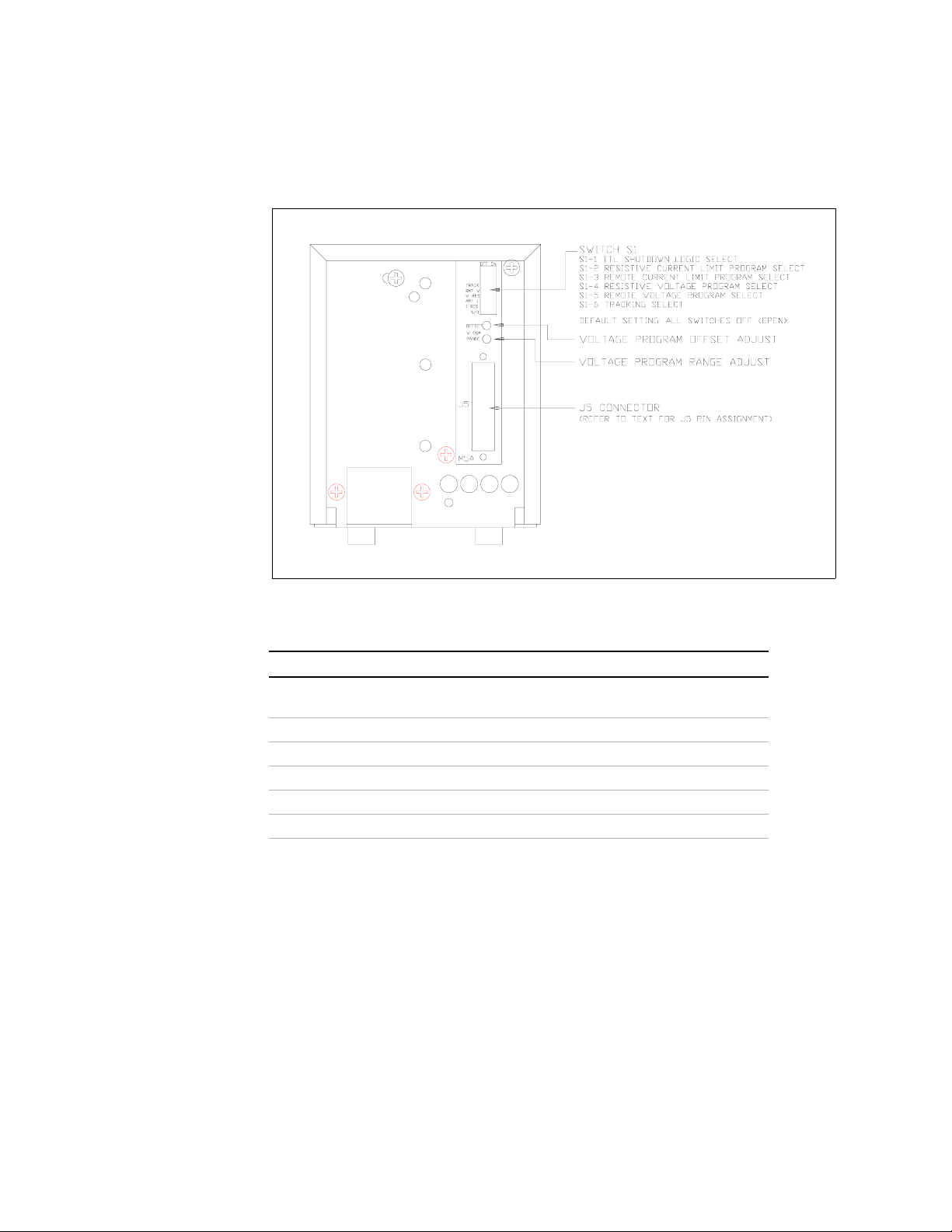
Rear Panel
Section 2. Installation and Configuration
Configuring
Rear Panel
Switch (S1)
Defaults
Figure 2.2 XT/HPD Rear Panel with APG Interface
Table 2.1 Rear Panel Switch S1 Default Settings
Setting Function
S1-1
TTL Shutdown Logic Select
(OPEN=negative logic, CLOSED=positive logic)
S1-2
S1-3 Remote Current Program Select
S1-4 Resistive Voltage Program Select
S1-5 Remote Voltage Program Select
S1-6 Tracking Select
Default: Local control (all switches OPEN).
Resistive Current Program Select
15
Page 18

Section 2. Installation and Configuration
Rear Panel J5 Connector
Rear Panel J5 Connector
Make analog interface connections via the rear panel 25-pin female DSUB connector
designated J5. To provide the lowest noise performance, we recommend you use
shielded-twisted pair wiring for making connections from external circuits to the J5
connector. Use the shortest leads possible. Ground the shield to pin 6 (auxiliary
ground) on the J5 connector or to the chassis via one of the J5 connector screws.
Note:In order to maintain isolation of power supply output, any programming
source must also be an isolated source.
J5 Connector
Pin
Assignments
Table 2.2 J5 Connector Pin Assignments
Pin Function
1 Over Voltage Protection Flag
2 TTL Shutdown Return
3 Not Used
4 Program Return
5 Program Return
6 Auxiliary Ground
7 Remote Voltage Program Select*
8 Remote Current Program Select*
9 Voltage/Current Limit Mode Indicator
10 + OUT
11 + OUT
12 RTN
13 RTN
14 Not Used
15 TTL Shutdown
16 Current Limit Program
17 Voltage Program
18 Current Readback
19 Voltage Readback
20 +10 V Reference OUT (10 mA max.)
21 Output Fail Flag*
22 + SNS
23 + OUT
24 RTN
25 RTN SNS
* Negative Logic: LOW = ACTIVE
16 Operating Manual for APG for XT/HPD Series Power Supply
Page 19

Calibration Adjustment
You can access most calibration potentiometers through the top of the unit, see
Figure 2.3. The exceptions are Voltage Program OFFSET and RANGE which are
on the unit's rear panel which can be seen on Figure 2.2.
Section 2. Installation and Configuration
Calibration Adjustment
Figure 2.3 APG Interface Calibration Adjustment Locations
17
Page 20

Section 2. Installation and Configuration
Calibration Adjustment
18 Operating Manual for APG for XT/HPD Series Power Supply
Page 21

Section 3. Operation
!
Remote Programming
Remote programming allows control of the power supply's output voltage and/or
current limit to shift from local operation at the front panel voltage and current
controls to external analog input sources. As you vary the programming source, the
power supply's output varies proportionally over its output range.
When you select remote voltage programming, the voltage contro l knob on the front
panel will not work. The same situation applies when you select remote current
programming: the remote option overrides the current control knob on the front
panel.
CAUTION
The programming signal return is internally referenced to the return sense (RTN
SNS) potential of the power supply. Therefore, you may connect the remote
programming source return to the power supply circuit at ONLY ONE of the
following nodes:
• APG Interface J5 connector pins 4 or 5 (program return), OR
• power supply output return when remote sense not used, OR
• power supply return sense (RTN SNS) when remote sense is connected.
Programming
Output
V olt age with a
0-10Vdc
Voltage
Source
If you do not observe this restriction, the power supply may operate erratically,
or, fuse F1 on the APG Interface PCB assembly may blow.
In order to maintain isolation of power supply output, use a programming source
which is also an isolated source.
1. Select remote voltage programming by moving the rear panel switch S1-5
(remote voltage program select) to the ON (closed) position.
Or, connect J5 pin 7 (remote voltage program select) to J5 pin 6 (auxiliary
ground). As these two control functions are wired in parallel, they function as a
logic OR.
2. Connect the voltage source between pin 17 (voltage program) and either pin 4 or
pin 5 (program return).
19
Page 22

Section 3. Operation
Remote Programming
3. Vary the external voltage from 0-10Vdc to cause the power supply output to vary
Note:Access the zero offset adjustment through the rear panel hole labelled
OFFSET. Access the full scale calibration adjustment through the rear panel hole
labelled RANGE. See Figure 2.2, pg. 15.
from 0-100% of rated output voltage. You may set the power supply's output
current limit using another source or the front panel current limit control.
Programming
Output
V olt age with a
0-10k
Resistance
Programming
Output
Current with
a 0-10 Vdc
Voltage
Source
1. Select remote voltage programming by moving the rear panel switch S1-5
(remote voltage program select) to the ON (closed) position.
Or, connect J5 pin 7 (remote voltage program select) to J5 pin 6 (auxiliary
ground). As these two control functions are wired in parallel, they function as a
logic OR.
2. Set rear panel switch S1-4 (resistive voltage program select) to the ON (closed)
position.
3. Connect a variable resistor between pin 17 (voltage program) and either pin 4 or
pin 5 (program return).
4. Adjust the resistance from 0-10kΩ to vary the power supply output from 0- 100%
of rated output voltage. You may set the power supply's output current limit
using another source or the front panel current limit control.
1. Select remote current limit programming by moving the rear panel switch S1-3
(remote current program select) to the ON (closed) position.
Or, connect J5 pin 8 (remote current program select) to J5 pin 6 (auxiliary
ground). As these two control functions are wired in parallel, they function as a
logic OR.
2. Connect the voltage source between J5 pin 16 (current program, positive) and
either pin 4 or pin 5 (program return).
3. Vary the external voltage from 0-10Vdc to cause the power supply current limit
to vary from 0-100% of rated output. You may set the power supply's output
voltage using another source or the front panel voltage control.
Access the zero offset adjustment and full range scale adjustment through top cover
slots as shown in Figure 2.3, pg. 17.
20 Operating Manual for APG for XT/HPD Series Power Supply
Page 23

Section 3. Operation
Remote Programming
Programming
Output
Current with
a 0-10k
Resistance
Programming
with a Fixed
+10V
Reference
1. Select remote current programming by external resistance by moving the rear
panel switch S1-3 (remote current program select) to the ON (closed) position.
Or, connect J5 pin 8 (remote current program select) to J5 pin 6 (auxiliary
ground). As these two control functions are wired in parallel, they function as a
logic OR.
2. Set rear panel switch S1-2 (resistive current program select) to the ON (closed)
position.
3. Connect a variable resistance between J5 pin 16 and either pin 4 or pin 5
(program return).
4. Adjust the resistance from 0-10kΩ to vary the power supply current limit from
0-100% of rated output. You may set the power supply's output voltage using
another source or the front panel voltage control.
The APG Interface J5 connector provides a +10 V reference output at pin 20 for
applications which require a fixed output voltage and/or current limit. The current
from this output must be less than 10 mA.
To program output voltage:
1. Connect resistor A between J5 connector pin 20 (+10 V reference out) and pin
17 (voltage program).
2. Connect resistor B between pin 17 (voltage program) and either pin 4 or 5
(program return).
To program current limit, follow the procedure used to set up for programming
output voltage, substituting pin 16 (current program) for pin 17.
+10 V
R
A
Vpgm
J5-20
J5-17
Vo = --------------
Where:
V
R
B
V
J5-4
Figure 3.1 Programming with a Fixed +10V Reference
R
V
OMAX RB
R
+ R
A
B
= programmed output of power supply
o
= rated maximum output of power supply
oMAX
+ RB > 1k
A
21
Page 24

Section 3. Operation
Readback and Status Indicators
Readback and Status Indicators
Voltage and
Current
Readback
Operating
Mode Status
Voltage Readback
• Connect a meter between J5 connector pin 19 (voltage readback) and either pin
4 or 5 (program return).
Range: 0-10V = 0-100% full rated voltage output of power supply
Current Readback
• Connect a meter between J5 connector pin 18 (current readback) and either pin
4 or 5 (program return).
Range: 0-10V = 0-100% full rated current output of power supply
Note:The voltage and current readback signals have adjustable offset and range.
These adjustments are accessible from the top of the power supply (see Figure 2.3,
pg. 17). The adjustments are independent of other power supply calibrations or
adjustments such that APG readback can be zero and range calibrated without
affecting other power supply parameters.
• Connect voltmeter between J5 connector pin 9 (voltage/current limit mode
indicator) and pin 6 (auxiliary ground).
Voltage Mode: active low open collector
Current Mode: high impedance open collector
Remote
Programming
Status
Output Fail
Flag
Remote programming status is available via J5 connector pins 7 (remote voltage
program select) and 8 (remote current program select). Reference to J5 connector at
either pin 4 or 5 (program return).
J5-7 LOW = Remote Voltage Program, HIGH=Local Front Panel Control
J5-8 LOW = Remote Current Program, HIGH=Local Front Panel Control
The Output Fail Flag (J5 connector pin 21) signal is HIGH (open collector) when any
one of the following conditions is true:
• AC input to the power supply is below operating limits.
• Over voltage protection is activated.
• TTL shutdown is active.
• Sense line protect circuit is active (excessive load line drop or load line(s) not
connected or fuse(s) in power supply blown).
22 Operating Manual for APG for XT/HPD Series Power Supply
Page 25

Section 3. Operation
Overvoltage Protection (OVP)
Overvoltage Protection (OVP)
The OVP circuit is designed to protect the load in the event of a remote programming
error, incorrect voltage control adjustment, or power supply failure. The protection
circuit monitors the output and reduces the output voltage and current to zero
whenever a preset voltage limit is exceeded. A red LED on the front panel indicates
when the OVP circuit has been activated. Set the OVP trip level at the front panel.
OVP Flag When the OVP has been activated, a signal of nominal +10V through 10k will be
present at pin J5-1. When no OVP condition exists, this signal will be 0V.
Setting the
OVP Trip
Level
1. Turn the power supply OFF.
2. Insert a small, flat-bladed screwdriver through the OVP ADJ (OVP Adjust) hole
in the front panel to turn the adjusting screw fully clockwise (one-turn screw).
3. Turn the unit ON and set the output to the desired trip voltage.
4. Slowly turn the adjusting screw counterclockwise until the red OVP indicator
lamp lights.
5. Turn the POWER switch to OFF.
6. Turn the voltage control knob to minimum.
7. Turn the POWER switch back ON and increase the voltage to check that the
power supply shuts off the output at the set voltage. Reference to J5 connector
pin 6 (auxiliary ground).
8. Reset the OVP circuit after activation by removing the overvoltage condition
and powering the unit OFF and back ON, or, by momentarily activating the TTL
remote shut down circuit. See “TTL Shutdown” for information about shut
down circuit operation.
23
Page 26

Section 3. Operation
TTL Shutdown
TTL Shutdown
TTL Shutdown allows the output of the power supply to be disab led by a logic level
signal. This input is optically isolated from the power supply output and will
withstand a highpot test potential of 600Vac minimum. When TTL shutdown is
activated, the front panel LED comes on.
• Connect the signal source between J5 connector pins 15 (TTL
• Set rear panel switch S1-1 (TTL shutdown) to ON (closed) to obtain positive
Notes:Minimum activation signal required: 2V at 500μA
shutdown/positive) and 2 (TTL shutdown return/negative).
logic (high signal enables output). The factory-set default is switch OPEN for
negative logic (high signal disables power supply output).
Switch SW1-1 Setting TTL Signal Level Output Condition
OPEN (Negative logic) HIGH
LOW
CLOSED (Positive logic) HIGH
LOW
OFF
ON
ON
OFF
Maximum activation signal allowed : 25Vdc
24 Operating Manual for APG for XT/HPD Series Power Supply
Page 27

Tracking
Section 3. Operation
Tracking
For tracking +/- outputs, use the following set-up:
• Set slave unit rear panel switch S1-5 (remote voltage program select) and switch
S1-6 (tracking select) to ON (closed).
• Connect master return (J5 connector pins 12, 13, or 24) to slave +OUT (J5
connector pins 10, 11, or 23).
• Connect master +OUT (J5 connector pins 10, 11, or 23) to slave voltage program
input (J5 connector pin 17).
Notes:
1. Master/slave power supplies must have the same output ratings.
2. Set switch S2 on the slave unit's APG Interface PCB to the correct model
number (factory preset). This requires that you remove the power supply cover.
3. Slave tracking can be calibrated by adjusting the unit's offset and range
potentiometers. See “Calibration Adjustment” on page 17.
4. As the slave is referenced to the master's output, the noise and ripple on the slave
may increase. In addition, if the master's output decreases due to current limit
acting, the output voltage of the slave will follow.
Figure 3.2 Master/Slave Tracking Configuration
25
Page 28

Section 3. Operation
Tracking
26 Operating Manual for APG for XT/HPD Series Power Supply
Page 29

Section 4. Calibration
Introduction
WARNING
Exercise caution when using and servicing power supplies. High energy levels can
be stored at the output voltage terminals on all power supplies in normal operation. In
addition, potentially lethal voltages exist in the power circuit and the output connector
of power supplies which are rated at 40V and over. Filter capacitors store potentially
dangerous energy for some time after power is removed.
You can calibrate the GPIB interface by adjusting the signal levels on the interface
card so that they correspond to the expected signal levels on the power supply's main
assembly . You may need to recalibrate the interface if you replace parts either on the
interface board or on the main power supply board, or if the unit falls out of
specification due to component aging drifts.
You can calibrate the GPIB Interface for:
• Voltage program
• Voltage readback
• Current program
• Current readback
• Overvoltage protection
The calibration procedures in this section are designed to be performed at an ambient
temperature of 25°C ± 5°C.
47
Page 30

Section 4. Calibration
Calibration Setup
Calibration Setup
1. Disconnect the supply's AC power.
2. Disconnect the load from the power supply you want to calibrate.
3. Remove the cover to access the GPIB Interface PCB calibration potentiometers.
4. Ensure the power supply is connected for local sensing (factory default).
5. Connect a digital voltmeter (DVM) for voltage or OVP calibration, or , a current
6. Ensure the correct IEEE primary address has been set (rear panel switches
7. Set the power supply to REMOTE mode (rear panel switch SW1-1 ON).
8. Connect the IEEE controller to the power supply at connector J8.
9. Reconnect the AC power. Turn unit ON and allow the unit to warm up for 30
shunt rated for the full output current of the supply and a DVM for current
calibration. See Figure 4.1, Voltage Calibration Setup or Figure 4.2, Current
Calibration Setup.
SW1-8 to SW 1-4). See “IEEE-488 Primary Address Selection” on page 24 for
information on address selection.
minutes.
48 Operating Manual for APG for XT/HPD Series Power Supply
Page 31

Voltage Mode Calibration
Section 4. Calibration
Voltage Mode Calibration
Voltage
Program
Power Supply
Positive Output
+
VOLTMETER
Figure 4.1 Voltage Calibration Setup
Negative Output
V
Power Supply
-
1. Connect the unit to the digital voltmeter as shown in Figure 4.1. See also
“Calibration Setup” on page 48, step 4.
2. Program the output to 5% of full scale voltage by sending the following
command string from the computer:
VSET2;ISET25 (for 1kW Model 40-25)
3. Adjust voltage programming of fset potentiometer R28 (VOFF) until the external
meter reading is within the power supply's voltage program accuracy
specification. Refer to specification tables in Section 1.
Example: ±75mV ±(0.3% (5% of 40V)) (for 1kW Model 40-25)
4. Program the output to full scale voltage by sending:
VSET40;ISET25 (for 1kW Model 40-25)
5. Adjust voltage programming full scale potentiometer R51 (VADJ) until the
external meter reading is within the power supply's voltage program accuracy
specification. Refer to specification tables in Section 1.
Example: ±75mV ±(0.3% of 40V) (for 1kW Model 40-25)
6. Repeat steps 2 to 5 (between VOFF and VADJ) for best linearity.
49
Page 32

Section 4. Calibration
Voltage Mode Calibration
Voltage
Readback
1. Connect the unit to the digital voltmeter (DVM) as shown in Figure 4.1.
(Optional step)
2. Program the output to 5% of full scale by sending the following command string
from the computer:
VSET2;ISET25 (for 1kW Model 40-25)
3. Perform a readback operation of the output voltage from the computer:
VOUT?
4. Adjust the voltage readback offset potentiometer R50 (VZERO) until the
readback value is within specification. Refer to the voltage readback accuracy
specification in Section 1.
Example: ±75mV ± (0.3% (5% of 40V)) (for 1kW Model 40-25)
5. Program the output to full scale voltage by sending:
VSET40;ISET25 (for 1kW Model 40-25)
6. Adjust the voltage readback full scale potentiometer R49 (VGAIN) until the
readback voltage value is within specification. Refer to the voltage readback
accuracy specification in Section 1 .
Example: ±75mV ± (0.3% of 40V) (for 1kW Model 40-25)
7. Repeat steps 2 (VZERO) to 5 (VGAIN) for best linearity.
50 Operating Manual for APG for XT/HPD Series Power Supply
Page 33

Current Mode Calibration
Figure 4.2 Current Calibration Setup
Power Supply
Positive Output
Current Sensing
+
Resistor
V
VOLTMETER
Power Supply
Negative Output
-
Section 4. Calibration
Current Mode Calibration
Current
Program
1. Ensure the current shunt has been connected to the power supply as shown in
Figure 4.2. See also “Calibration Setup” on page 48, step 4.
2. Program the output to 5% of full scale current by sending the following
command string from the computer:
VSET40;ISET1.25 (for 1kW Model 40-25)
3. Adjust current programming offset potentiometer R27 (IOFF) until the meter
reading is within the power supply's current program accuracy specification.
Refer to specification tables in Section 1.
Example: ±140mA ± (0.15% (5% of 25A)) (for 1kW Model 40-25)
4. Program the output to full scale current by sending:
VSET40;ISET25 (for 1kW Model 40-25)
5. Adjust current programming full scale potentiometer R47 (IADJ) until the meter
reading is within the power supply's current specification. Refer to specification
tables in Section 1.
Example: ±140mA ± (0.15% of 25A) (for 1kW Model 40-25)
6. Repeat steps 2 to 5 (between IOFF and IADJ) for best linearity.
51
Page 34

Section 4. Calibration
Current Mode Calibration
Current
Readback
1. Ensure the current shunt has been connected to the power supply as shown in
Figure 4.2. See also “Current Calibration Setup” on page 51, step 4. Connecting
a DVM is optional.
2. Program the output to 5% of full scale current by sending the following
command string from the computer:
VSET40;ISET1.25 (for 1kW Model 40-25)
3. Perform a readback operation of the output current from the computer:
IOUT?
4. Adjust the current readback offset potentiometer R38 (IZERO) until the
readback value is within the current readback accuracy specification. Refer to
specification tables in Section 1.
Example: ±140mA ± (0.15% (5% of 25A)) (for 1kW Model 40-25)
5. Program the output to full scale current by sending:
VSET40;ISET25 (for 1kW Model 40-25)
6. Perform a readback operation of the output current from the computer:
IOUT?
7. Adjust the current readback full scale potentiometer R45 (IGAIN) until the
readback current value is within specification. Refer to specification tables in
Section 1.
Example: ±140mA ± (0.15% of 25A) (for 1kW Model 40-25)
8. Repeat steps 2 (IZERO) to 7 (IGAIN) for best linearity.
52 Operating Manual for APG for XT/HPD Series Power Supply
Page 35

Over Voltage Protection (OVP) Calibration
1. Connect the unit as for voltage mode calibration. See Figure 4.1. See
“Calibration Setup” on page 48, step 4. (Optional step.)
2. Program the OVP setting to 50% of the full scale voltage by sending the
following command string from the computer:
OVSET20 (for 1kW Model 40-25)
3. Program the output voltage to about 40% of the OVP set value by sending:
VSET16;ISET25 (for 1kW Model 40-25)
4. Increment the programmed output voltage from the computer until the OVP
fires. The red OVP LED on the front panel will light up.
5. Clear the supply settings by sending:
CLR
6. and reset the OVP condition with:
RST
Section 4. Calibration
Over Voltage Protection (OVP) Calibration
7. The OVP trip point is in specifi cation if the meter value shown when OVP fires
is within the total of the set trip point ± the OVP program accuracy specification
for the power supply model. See Section 1.
Example: 20V ± 400mV (for 1kW Model 40-25)
8. If the OVP trip point was out of specification, adjust potentiometers R19
(OVPREF, coarse adjustment) and R23 (OVPOFF, fine adjustment). Repeat
steps 2 to 5 until the unit operates within specified values again.
9. Check for linearity by testing the OVP trip point at 10% and 90% of full scale
voltage.
53
Page 36

Section 4. Calibration
Over Voltage Protection (OVP) Calibration
54 Operating Manual for APG for XT/HPD Series Power Supply
 Loading...