

Ametek ABCE702-11RMED, ABCE1002-11R, ABCE702-22R, ABCE702-22RMED, ABCE1002-11RMED User Manual
...Page 1

Security II Rackmount Series
Uninterruptible Power Manager
For use with 700VA, 1000VA, 1440VA, 2200VA and 3000VA
Page 2

2
A01-00104 Rev A
1.0 - Introduction .................................................................... 6
2.0 - Safety Instructions ......................................................... 8
3.0 - Installation ..................................................................... 12
4.0 - Operation ....................................................................... 17
5.0 - Maintenance .................................................................. 22
6.0 - Troubleshooting ............................................................. 27
7.0 - Warranty ........................................................................ 29
8.0 - Specications ................................................................ 30
TABLE OF CONTENTS
Page 3

3
A01-00104 Rev A
IMPORTANT NOTICE ON BATTERY WARRANTY
The warranty policy stated in Section 8 is not valid for applications in
which the UPM is regularly and intentionally disconnected from AC
mains power. The two year battery warranty applies only to products
that are properly installed and consistently connected to AC mains
power, except during utility outages.
Products regularly and intentionally disconnected from AC mains
power will experience substantially reduced battery life. The standard
warranty term does not apply in these cases and is supplanted by a
90-day warranty from time of shipment. The warranty provides for the
replacement of the battery or battery systems in the event that the
batteries do not meet performance specications as determined by our
company exclusively.
Page 4
4
A01-00104 Rev A
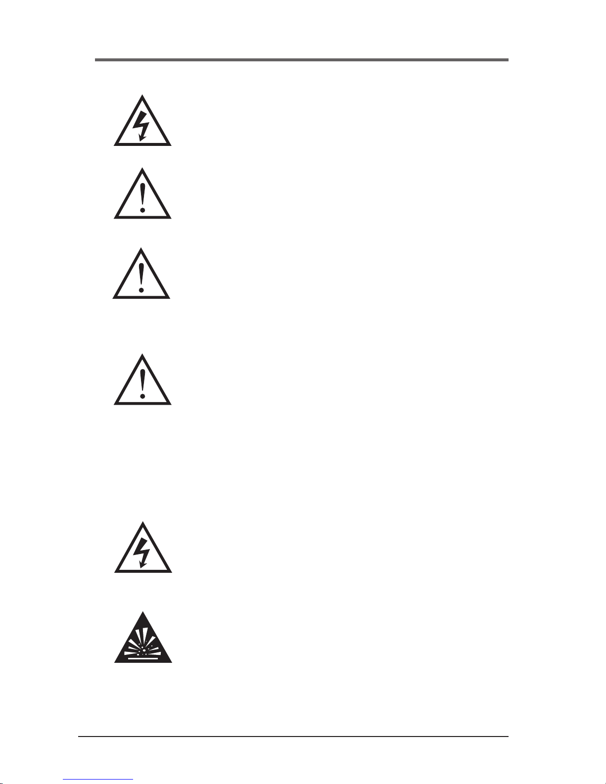
Danger- The danger symbol is used to indicate
imminently hazardous situations, locations, and
conditions which, if not avoided, WILL result in death,
serious injury, and/or severe property damage.
Caution- The caution symbol is used to indicate potentially hazardous situations and
conditions which, if not avoided, may result in
injury. Equipment damage may also occur.
Warning- The warning symbol is used to indicate
potentially hazardous situations and conditions which,
if not avoided, COULD result in serious injury or
death. Severe property damage COULD also occur.
Attention- The attention warning symbol is used to
indicate situations and conditions that can cause
operator injury and/or equipment damage.
Other warning symbols may appear along with the
Danger and Caution symbol and are used to specify
special hazards. These warnings describe particular areas where special care and/or procedures are required
in order to prevent serious injury and possible death.
Electrical warnings- The electrical warning symbol is a
lightning bolt mark enclosed in a triangle. The electrical
warning symbol is used to indicate high voltage locations and conditions may cause serious injury or death.
Explosion warnings- The explosion warning
symbol is an explosion mark enclosed in a triangle. The explosion warning symbol is used to
indicate locations and conditions where molten,
exploding parts may cause serious injury or death
if the proper precautions are not observed.
DANGER
CAUTION
WARNING
ATTENTION
Page 5

5
A01-00104 Rev A
Alternating Current
Refer to instruction manual/booklet.
Two person lift.
Page 6

6
A01-00104 Rev A
1.0 INTRODUCTION
Thank you for your purchase of the Security II Series Rackmount UPM (
hereafter referred to as “UPM”). We manufacture two versions of the UPM
– a standard version, and a medical version listed to UL60601-1 and cUL
C22.2 No. 60601.1. In addition, all models are compatible with International
electrical distribution systems. International versions are UL listed (Medical
listed to IEC60601-1 and EN60601) and carry the CE Mark. We’ve prepared
this document to help familiarize you with the functions and controls of this
product. If, after reviewing this manual, you have any questions at all, please
feel free to contact our technical support team by phone (1-800-369-7179) or
email us at service.powervar@ametek.com.
We are a global provider of power management solutions, headquartered in
Waukegan, Illinois, with international sales and distribution ofces in Swindon, United Kingdom, Toronto, Canada, Mexico City, Mexico and Germany.
All solutions incorporate a high energy surge diverter, a noise lter and a low
impedance isolation transformer. Together these components prevent power disturbances from destroying, degrading or disrupting system operations.
Registering your Product
Please take a few moments to register your product purchase. Registration
is easy and quick via the product registration page found on our website at
www.powervar.com.
Page 7
7
A01-00104 Rev A
General
The Security II UPM (hereafter refered to as “UPM”) systems are the most
advanced, line interactive, true sinewave UPS products available for your
application. Each model is designed to provide total protection for your
system from a complete range of power quality problems. UPM systems will
protect your installation from normal mode voltage impulses, electrical noise,
sags, surges, brownouts, and blackouts. Each UPM contains a low impedance isolation transformer, it completely eliminates common-mode (neutralto-ground) voltages that are a constant threat to the reliable operation of
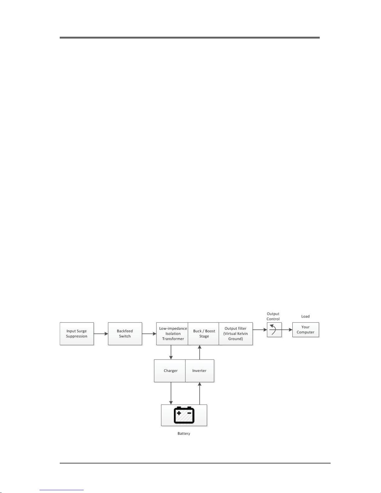
microprocessor-based systems. When AC power is present, UPM constantly
lters and conditions the power supply. When AC power fails, the UPM uses
its internal, maintenance-free battery to supply reserved power to your computer system. Regardless of whether or not commercial power is present, the
UPM is consistently on the job. Ensuring a fully conditioned, safely managed
interface between your computer system and its electrical power supply.
Figure 1 illustrates the basic operation of the UPM.
Figure 1
Page 8
8
A01-00104 Rev A
2.0 SAFETY INSTRUCTIONS
IMPORTANT - SAVE THESE INSTRUCTIONS
THIS MANUAL CONTAINS IMPORTANT SAFETY INSTRUCTIONS.
KEEP THIS MANUAL HANDY FOR REFERENCE.
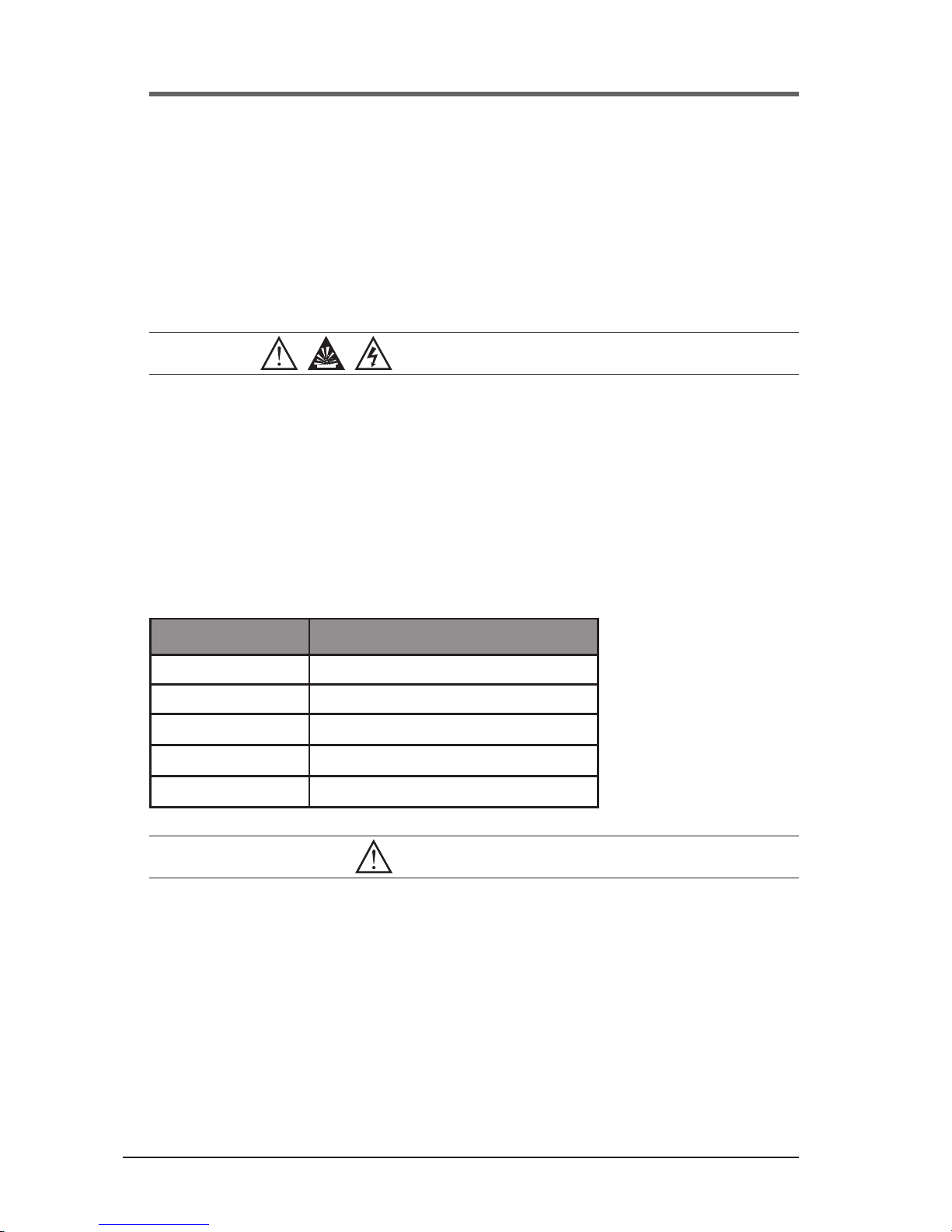
CAUTION
A battery can present a risk of electrical shock. Short-circuit currents can
be extremely high and can create severe burns as well as the risk of re or
explosion from vented gases. Always observe proper precautions.
When replacing batteries, use the same quantity, rating and type of batteries
used by the company. The batteries used in this UPM are sealed lead-acid
and are maintenance free. Proper disposal of batteries is required. Refer to
your local codes for disposal of batteries.
UPM Rating Quantity and Battery Rating
700 VA 4 X 23W @ 12 VOLT
1000 VA 4 X 23W @ 12 VOLT
1440 VA 4 X 23W @ 12 VOLT
2200 VA 8 X 23W @ 12 VOLT
3000 VA 8 X 23W @ 12 VOLT
CAUTION
• This UPM contains voltages which are potentially hazardous. All re-
pairs should be performed by qualied service personnel.
• To reduce the risk of re, connect only to a circuit provided with 20 am-
peres maximum branch circuit over-current protection in accordance
with the National Electric Code, ANSI/NFPA 70.
• The UPM has its own internal energy source (battery). The output receptacles of the UPM may be live even when the UPM is not connected to an AC Supply.
Page 9

9
A01-00104 Rev A
STATEMENT OF INTENDED USE
The medical UPMs are intended to protect medical, non-medical computer
equipment and medical devices that need battery backup, surge protection,
voltage regulation and line noise ltering in and around patient care areas.
Safe and continuous operation of the UPM depends partially on the care taken by users. Please observe the following precautions. Not following these
could result in warranty being voided.
NOTE:
• The UPM is intended for stationary use.
• UPM is not intended for patient contact or for installation that will cause
accidental contact of patients.
• Do not use this UPM for life support applications in which a malfunction
or failure of the UPM system could cause failure or signicantly alter
the performance of a life-support device.
• Do not use this UPM near or around ammable gases. Do not use this
UPM within oxygen-enriched atmospheres.
• Do not disassemble the UPM.
• UPM is CLASS 1 equipment.
• Do not attempt to power the UPM from any receptacle except a properly grounded receptacle that matches the input plug provided with the
UPM.
• Do not place the UPM near water or in environments of excessive
humidity.
• Do not allow liquid or any foreign object to get inside the UPM.
• Do not block air vents on the front of the UPM.
• Do not plug appliances such as hair dryers, fans, heaters, etc. into the
UPM.
• Do not place the UPM under direct sunshine or close to heat emitting
sources (excessively warm temperatures will shorten battery life).
• This UPM is intended for installation in a temperature controlled, indoor
area free of conductive contaminants.
• The AC power source for the UPM should be conveniently near the
UPM and easily accessible – avoid extension cords or temporary power strips to power the UPM.
Page 10

10
A01-00104 Rev A
• The total leakage current of the UPM and consumer connected equipment should not exceed 3.5 mA for non-medical units.
• Not for use in a computer room as dened in the Standard for the
Protection of Electronic Computer/Data Processing Equipment, ANSI/
NFPA 75.
• The socket-outlet shall be installed near the equipment and shall be
easily accessible.
• The battery should be disconnected from the UPM by unplugging at its
quick connectors when maintenance or service work inside the UPM is
necessary.
• Do not dispose of batteries in a re – batteries may explode.
• Do not open or mutilate batteries. Doing so may release electrolyte or
other toxic substances, which may be harmful to the skin, eyes, or the
environment.
A battery can present a risk of electric shock and high short circuit current.
The following precautions should be observed when working with batteries:
• Remove watches, rings, or any other metal jewelry or objects which
may make contact with the battery.
• Use tools with insulated handles.
Unit is suitable for IT applications.
Page 11

11
A01-00104 Rev A
FCC ISSUES
Attention
This UPM has been tested and found to comply with the limits for a Class A
digital devices (Class B compliance optional), pursuant to Part 15 of the FCC
rules. These limits are designed to provide reasonable protection against
harmful interference in both residential and commercial environments.
This equipment generates, uses and can radiate radio frequency energy
and if not installed and used in accordance with the instructions, may cause
harmful interference to radio communications. However, there is no guarantee that interference will not occur in a particular installation. If this equipment
does cause harmful interference to radio and/or television reception, which
can be determined by turning the UPM equipment on and off, the user is
encouraged to try to correct the interference by one or more of the following
measures:
Relocate the UPM
Relocate the load.
This device complies to Part 15 of the FCC Rules. Operation is subject to the
following two conditions: (1) this device may not cause harmful interference
and (2) this device must accept interference received, including interference
that may cause undesired operation.
Page 12

12
A01-00104 Rev A
3.0 INSTALLATION
Some units may require 2 people to lift.
Security II Rackmount Quick Start Guide
This unit is shipped with the internal batteries disconnected.
Before starting the UPM, please follow these battery connection instructions.
1. Remove UPM from the box
2. Attached included
outlet cord and plug
UPM into wall.
Continued on side 2
3. Remove the UPM
front plastic cover and
metal battery cover
by removing the screws.
Page 13
13
A01-00104 Rev A
3 sec.
5. Put they metal battery
cover and the front
cover back on and
remove the yellow
warning label.
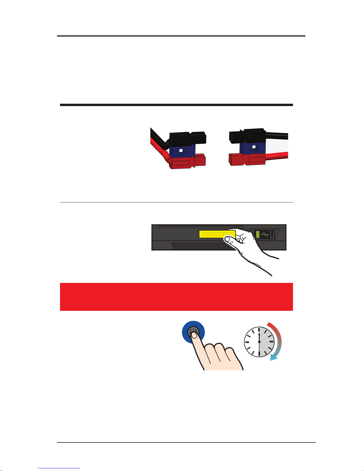
6. Turn UPM on by pressing
ON button for 3 seconds
IMPORTANT:
Wait 15 seconds after inserting the battery plug(s) before pressing the ON switch on the UPM front panel.
If you ship the UPM to another location at a later date, disconnect the battery plug(s) first to ensure that safety is maintained during shipment.
4. Connect battery
connector.*
Battery connectors may
be partially hidden on
the side of the battery.
*The 2.2 & 3KVA units connect 2 batteries
Security II Rackmount Quick Start Guide
Page 14

14
A01-00104 Rev A
UNPACKING THE UPM
CAUTION
• Unpacking the unit in a low-temperature environment may cause
condensation to occur in and on the unit. Do not install the unit until
the inside and outside of the unit are absolutely dry {hazard of electric
shock}.
• The unit is heavy. Use caution when unpacking and moving the unit.
Use care when moving and opening the carton. Leave the components packaged until ready to install.
To unpack the unit and accessories:
1. Open the outer carton and remove the accessories packaged with
the unit.
2. Carefully lift the unit out of the outer carton.
3. Store the carton for future use.
Place the unit in a protected area that has adequate airow and is free of
humidity, ammable gas and corrosion.
NOTE:
Before installation, please read and understand the following
instructions. Carefully examine the carton for damage. Notify the
carrier immediately if damage is observed. Be sure to save the carton
should you ever need to ship the UPM for repair or maintenance.
This UPM is intended for indoor use only. Although your
UPM is very rugged, its internal components are not sealed
from the environment. The UPM must be installed in a
protected environment away from heat producing appliances such as furnaces, radiators, and heaters. Protect the
UPM from exposure to dripping or standing water and high
humidity or condensing air conditions.
Page 15

15
A01-00104 Rev A
Rackmount Installation Guide
** Example of 4U unit* Example of a 2U unit
1. Assemble the side rails and
secure each with (2) screws.
DO NOT TIGHTEN.
2. Attach front of the rails to
front of rack with (1) fastener
for each side in the upper
mounting hole.
3. Attach rear of rails to rear of
rack with the (2) fasteners for
each side.
4. Tighten the (2) screws used to
assemble each rail in step 1.
5. For 2U
*
UPMs and battery
cabinets, attach (1) angled
mounting bracket to each side
of the UPM and/or each side
of the battery cabinet using
the (8) screws provided.
6. For 4U
**
UPMs - attach (2)
angled mounting brackets to
each side of the UPM using
the (16) screws provided.
7. Lift the battery cabinets and
UPM onto the mounting rails
and slide each into position.
8. Secure the 2U UPM and
battery cabinet with (4)
fasteners and the 4U UPMs
with (8) fasteners provided.
Rackmount UPM and the
external battery cabinet are
designed to be floor standing as
an alternative to rack mounting.
The UPM and external battery
cabinets use identical mounting
hardware and the procedure for
mounting is the same for both.
Each unit and each battery
cabinet must be mounted
to their own rail kits that
are included.
Floor Standing Installtion
Middle Rack Installation Standard Rack Installation
Page 16

16
A01-00104 Rev A
Rackmount Installation Guide
INSPECTING THE UPM
If any equipment has been damaged during shipment, keep the shipping cartons and packing materials
for the carrier or place of purchase and file a claim for shipping damage:
1. File with the carrier within 15 days of receipt of the equipment;
2. Send a copy of the damage claim within 15 days to your service representative.
WARNINGS
Use all supplied mounting hardware on each UPM and External Battery Cabinet.
NEVER depend on devices installed on lower levels to support other devices.
Two people are recommended for safe installation.
Never attempt to mount the UPM or external battery cabinet with the from mount ears
only. Continuous support is required throughout the mounting procedure to prevent
damage or injury.
Page 17

17
A01-00104 Rev A
4.0 OPERATION
NOTE:
In order to operate the UPM, you must rst plug the battery enable
plug(s) into the battery enable socket(s) behind the front panel of the
UPM.
On/Off Button
The On/Off button is a dual function control:
• When the UPM is off and AC power is present to the UPM input,
pressing the On/Off button for more than 2 seconds will turn the UPM
output on.
• If battery is connected, pressing the On/Off switch for 2 seconds or
more will “cold-start” the UPM on its internal battery with no incoming
AC present.
• When the UPM is on, pressing the On/Off button for more than 2
seconds will turn off the UPM output power.
Test/Silence Button
The Test/Silence button is a dual function control:
• Pressing the Test/Silence button when AC power is present and the
UPM is operating causes the UPM to enter a self test mode in which
it tests both battery and inverter for a few seconds before returning to
the AC supply. We recommend you close all open les before initiating
self-test.
• When AC power fails, the UPM warns you with an audible alarm. The
Test/Silence button is used to silence the alarm. When battery power
begins to run low, the audible alarm will automatically return and beep
at a faster rate.
Page 18

18
A01-00104 Rev A
Load Monitor
The Load Monitor is a six-segment LED display that shows the current load
percentage. The rst 5 LED’s each indicate approximately 20% load, with the
6th red LED showing the UPM is overloaded.
Battery Charge Monitor
The Battery Charge Monitor is a ve-segment LED display that shows the
charge capacity of the internal battery from zero to 100%. Each LED indicates
approximately 20% of full charge.
Site Wiring Fault Indicator – (120 VAC models only)
The “SF” symbol will be displayed on the front panel of the UPM if it is
connected to an improperly wired AC receptacle. This is to indicate a missing
safety ground wire or a reversal in phase and neutral wiring. If the “SF”
is displayed on the front panel you should contact a qualied electrician
immediately.
NOTE:
Do not operate the UPM if the Site Wiring Fault LED is illuminated.
When lit, the LED is indicating a wiring condition, which may represent
a hazard of re or electrocution. In addition, improper wiring may create
reliability problems for both the UPM and the connected system. Never
use a 3-blade to 2-blade adapter (often called a “cheater”) to power UPM.
These devices remove the safety ground connection to the UPM and will
cause the Site Wiring Fault LED to illuminate.
Page 19
19
A01-00104 Rev A
Display Functionality
The location should provide adequate airflow around the UPM. Provide a minimum 3” clearance on all sides for proper ventilation.
Applying Power to the UPM
Connect the power cord to a verified grounded 3 wire receptacle. Verify
that the Site Wiring Fault “SF” is off (120 VAC models only). Once properly
connected and initially checked, turn on the UPM by pressing and holding the
front panel On/Off switch for 3 seconds.
Operational Tests
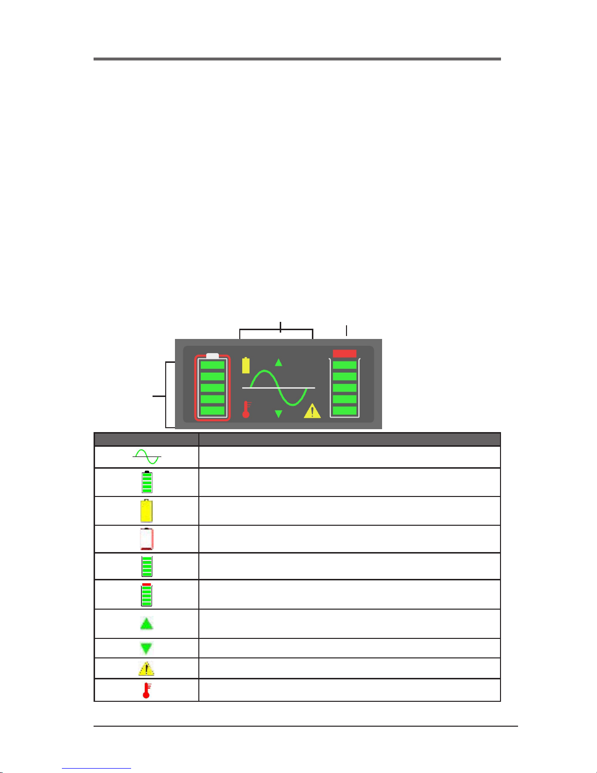
Observe the front panel of the UPM. The following table shows system status
behavior.
UPM LED DISPLAY UNIT STATUS
UPM output on
Battery charge status in 20% increments
UPM in battery operation due to improper incoming AC voltage
Battery fault or battery disconnected
UPM load status in 20% increments
UPM overloaded
Unit in buck operation due to high incoming AC voltage
Unit in boost operation due to low incoming AC voltage
Fault
UPM over temperature
UPM Front Panel
Output
Battery
System Status
Page 20

20
A01-00104 Rev A
UPM Load and Battery Indicators
Example:
UPM display showing normal operation
(Fully charged batteries with 60% load shown)
UPM display showing in battery backup operation
(Batteries 80% charged with 60% load shown)
UPM display showing an overload condition (Batteries 100%
charged and greater than 100% load shown)
UPM display showing over-temperature condition
(Batteries 80% charged with 80% load shown)
UPM display showing a bad battery condition
(Inspect or replace battery unit loaded to 60%)
NOTE:
Depending on the charge state of the battery, it is possible that the
battery charge level LEDs may be ashing (this is normal).
Initial Startup
With the connected equipment powered off, perform an initial test of the
UPM backup function by pressing the Test/Silence button on the front pan-
el. During this test, the Battery LED ( ) on the front panel should briey
illuminate. It is also possible to test the backup function by unplugging the
UPM input power cord. If you choose to test the UPM in this manner, you
will note that the UPM will beep every few seconds while the power cord is
unplugged. The Battery LED ( ) will also illuminate constantly.
Once you have performed an initial test of the UPM backup function, turn on
the connected computer equipment. Verify that the unit is not overloaded. If
the unit is overloaded all load LED’s will be on the fault LED ( ) will ash,
remove the least critical devices from the UPM one by one until the overload
LED is extinguished. With the connected loads powered up, perform the
backup test once again by pressing the Test/Silence button or unplugging the
UPM. When this nal test is completed, the UPM will be ready to use.
Page 21

21
A01-00104 Rev A
Reference the below UPM fault code chart to identify the status of the UPM.
UPM Status Code Denition
IF Inverter fault
BE Back-Feed fault
HL Unit is off due to a high line
LL Unit is off due to a low line
DB Unit is off due to a low battery
FF Fan fault
SF Site wiring fault
NOTE:
• If the UPM is on continuously, it will perform an auto battery test every
six days.
• If you are utilizing MopUPS Pro software, you can congure the system to automatically self-test periodically.
• The UPM is shipped with a charged battery, but some discharge
naturally occurs during storage and shipment. You may use the UPM
immediately, but you should realize that backup time may be less than
the stated rating until the UPM battery has had at least six hours to
charge.
• We recommend that you do not plug laser printers into the UPM. Laser
printers are known to draw large amounts of current when the fuser/
heater assembly is energized. Laser printers can easily overload the
UPM or create a low voltage condition that can interfere with the operation of the Voltage Manager circuit.
Rear Panel - Rack mount
ON
OFF
123 4
Page 22

22
A01-00104 Rev A
5.0 MAINTENANCE
Storage
The UPM may be stored for extended periods in an environment that does
not subject the UPM to extremes of temperature or humidity. When storing
for extended periods, the battery should be charged every six months. If the
storage location is characterized by above normal temperature, the battery
should be recharged every two months. The UPM does not need to be
turned on for charging to occur – it only needs to be plugged in with batteries
connected.
NOTE:
This product is not designed for continuous use on batteries.
Attention
Important Information
The batteries inside this UPM are a special type called “sealed lead-acid”.
These batteries use a non-liquid electrolyte, which makes it possible to
use them in any physical orientation. The batteries are designed to last
from two to ve years. Their actual life span will depend on several factors
including how often power outages occur, how long power outages last,
and the temperature of the environment in which the UPM operates.
Frequent, long duration power outages will shorten battery life more
than infrequent, short duration outages. Consistent high temperatures
in the area where the UPM is used will also shorten battery life.
The UPM is equipped with a Low/Replace Battery LED ( ) on the front
panel. If the LED illuminates, you should make sure that the battery has at
least six hours to charge without a power interruption. Inadequate (much
shorter than usual) backup time, premature low battery alarm sounds, and
persistent Low/Replace Battery LED illumination are all good signs that the
batteries inside your UPM requires replacement. The batteries inside your
UPM are designed to be replaced by an authorized service personnel only.
Page 23

23
A01-00104 Rev A
Please familiarize yourself with the following precautions before proceeding
with battery replacement.
WARNING
Servicing of batteries should always be performed or supervised by someone who has read and understood the following precautions and who understands the hazards associated with storage batteries. This procedure should
not be performed by someone who is unauthorized or who is incapable of
following these precautions.
CAUTION
• Only the battery assembly in this unit is user serviceable (non-medical
units only). The battery compartment is accessed by removing the front
panel as described in the following instructions. No other user serviceable parts are contained in this UPM. Do not remove any cover other
than the front battery access panels.
• A battery (even a depleted one) can deliver very high currents when
short-circuited. There is a danger of electrical shock. Remove all
watches, rings, bracelets or other metal objects. Use only tools with
insulated handles.
• Do not dispose of batteries in a re. There is a danger of explosion.
• Do not dispose of batteries in an environmentally unfriendly manner.
Batteries may be returned for proper disposal.
• Do not open or mutilate the batteries. This may release electrolyte that
is toxic to the environment and harmful to the skin and eyes.
• Replacement batteries may be ordered by phone or via our website at
www.powervar.com. If purchasing batteries from another source, be
sure to use the type and quantity of batteries.
• Medical units have no user serviceable parts inside.
Page 24

24
A01-00104 Rev A
User Replaceable Battery (Non-medical units only)
Eventually every UPM requires a new battery. We expect the battery in your
UPM to last a minimum of two years – perhaps longer if power outages are
short and infrequent. The UPM makes battery replacement by the user fast
and easy. It is not necessary to turn off the UPM or the connected system.
The UPM allows the battery to be “hot-swapped” while the system is running.
NOTE:
Changing the batteries in this UPM is designed to be a safe and simple
procedure. Batteries may be replaced while the UPM is on and providing
power to the connected load. You should remember, however, that if a
power outage occurs after the old batteries are disconnected and before
the new batteries are installed, power will be lost to your connected system and components.
CAUTION
RISK OF EXPLOSION IF BATTERY IS REPLACED BY INCORRECT TYPE.
When replacing batteries, co tact Powervar for correct battery replacement
kits.
VA Rating Replacement Battery Kit Part No.
700/1000/1440 58870-01
2200/3300 58870-02
CAUTION
Page 25

25
A01-00104 Rev A
Risk of Energy Hazard, 12V, maximum 23 Ampere-hour batteries. Before
replacing batteries, remove conductive jewelry such as chains, wrist watches, and rings. High energy through conductive materials could cause severe
burns.
CAUTION
Do not dispose of batteries in a re. The batteries may explode.
CAUTION
Do not open or mutilate batteries. Released material is harmful to the skin
and eyes. It may be toxic. A battery can present a risk of electrical shock
and high short circuit current. The following precautions should be observed
when working with batteries:
• Remove watches, rings or other metal objects.
• Use tools with insulated handles.
• Wear rubber gloves and boots.
• Do not lay tools or metal parts on top of batteries.
• Disconnect the charging source prior to connecting or disconnecting
battery terminals.
• Determine if battery is inadvertently grounded. If inadvertently grounded remove source from ground. Contact with any part of grounded
battery can result in electrical shock.
NOTE:
If you have read and understood the cautions preceding this section, you
may proceed with the following steps. Consult the gure on page 26 to
assist you in the following battery replacement procedure.
Page 26

26
A01-00104 Rev A
2. Slide to the right then tip away from the
front of the unit slightly.
3. Gently remove bezel in direction of arrow.
5. Removing Front and Battery Retention Plate
*
UPM 2U UPS (700VA, 1000VA, 1500VA)
The batteries for this unit can be changed while the unit is on. Unit's alarm will
beep while changing the battery. To replace the battery pack inside the UPS:
4. Once the bezel is removed, unscrew the two screws on the battery retention plate located on the
center of the unit and remove the plate by sliding slightly to the right to disengage the hooks.
6. Disconnect the battery from the UPS by grasping and pulling the battery connectors straight
out. Slide the battery out from the UPS.
7. Slide new battery into the UPS and reconnect proper colors to connectors (red/red,
black/black). The battery connector is polarized and will only fit one way. Make sure it is
completely installed.
8. Replace and secure the battery retention plate with the screws. Replace the front bezel by
reversing all three steps required previously for removal.
NOTE: Do not replace the front bezel without first securing the battery retention plate.
UPM 4U UPS (2200VA, 3000VA)
Battery replacement procedure is the same as for the 2U units above. However there are two
sets of batteries, each located behind the front bezels on the 4U UPS.
NOTE: Both sets of batteries must be replaced at the same time to ensure proper operation and
expected runtimes.
See “Instruction for Returning a Depleted Battery Pack” for instructions on returning
depleted battery(s) to AMETEK Powervar.
Battery packs can be replaced without turning
off the power or disrupting the protected
equipment.
After replacing the batteries in the Security II,
the LED display should illuminate all five bars
in the battery icon. If any of the bars are
flashing, the batteries are in the process of
charging.
If charging does not complete within 4 to 8
hrs, contact Technical Support.
Technical Support
24-hour technical support, to contact Technical
Services call:
(847) 596-7000 | Toll free: (800) 369-7179
Europe: +44 (0) 1793 553980
E-Mail: rma.powervar@ametek.com
Please check with Technical Services before
attempting to repair or return any product. If a
unit needs repair or replacement, Technical
Services will issue a Return Material
Authorization (RMA) number along with
instructions on how to return the product.
Instructions for Returning a
Depleted Battery Pack
We provide pre-paid return of depleted
batteries with all replacement battery
purchases. Just follow these simple steps:
1. Remove the new battery pack and install it
in the unit as per the installation
instructions. Put the FEDEX label aside
2. After the battery pack has been replaced,
place the depleted battery pack in the box
the same way the new battery was
packaged and seal the box.
3. Follow the return instructions on the back
of the FEDEX label and affix to the box
4. To return for proper recycling (at no cost to
you), give the
box to any FEDEX pick-up driver or call
1-800-393-4585 for the nearest drop off
location.
Security II Rackmount UPS
Battery Replacement Instructions
1. Pull bezel slightly at the left corner.
Page 27

27
A01-00104 Rev A
6.0 TROUBLESHOOTING
The troubleshooting information provided in this section should help you
discover the cause of most commonly encountered difculties. Before following the troubleshooting steps provided, be certain that you have veried the
following items:
• The UPM should be plugged into a properly working outlet.
• The line voltage to the UPM is within specied boundaries.
• The circuit breaker on the rear panel of the UPM has been reset.
• The battery enable plug(s) is installed.
Problem Possible Cause Action you should take
UPM does not
power up and has
no audible alarm
1. On/Off Button not pressed
long enough.
2. No incoming line voltage
or voltage too high or too
low.
3. UPM input power cord is
not plugged in.
4. Rear panel circuit breaker
is tripped.
1. Press and hold the On/Off switch
for 3 seconds min.
2. Check wall socket and test for
proper line voltage.
3. Plug in input power cord.
4. Reduce load and reset circuit
breaker.
UPM Over-
load LED’s are
illuminated and
continuous audible
alarm sounds
UPM is overloaded. Reduce load by removing the least
critical load items from the UPM
output.
Low/Replace
Battery LED is
illuminated
Battery voltage is too low or
battery is dead.
Recharge battery for at least six
hours and reset UPM. If LED is still
illuminated, replace the battery.
Site Wiring Fault
LED is illuminated
Site wiring problem. Contact a qualied electrician to
verify wiring at this site.
Backup time is
less than expected
Battery is not fully charged or
battery is dead.
Recharge battery for at least six
hours and retest back up time.
UPM is normal,
but the computer
will not turn on.
Computer input power cord
is loose or not connected.
Connect the power input power
cord.
Page 28

28
A01-00104 Rev A
Output Fuse Rating Chart
Work to be done only by qualied service personnel. It is critical that the
same type and rating of fuses are used:
Replace with same type and rating of fuse
fuse must be rated to IEC 60127-2
Model Fuse rating (slow-blow)
ABCE702-11R / ABCE702-11RMED 250 VAC 6.3 A
ABCE702-22R / ABCE702-22RMED 250 VAC 3.15 A
ABCE1002-11R / ABCE1002-11RMED 250 VAC 8 A
ABCE1002-22R / ABCE1002-22RMED 250 VAC 5 A
ABCE1442-11R / ABCE1442-11RMED 250 VAC 12.5 A
ABCE1442-22R / ABCE1442-22RMED 250 VAC 6.3 A
Technical Support
The Company provides technical product support during our regular
business hours of 8:00 a.m. to 5:00 p.m. Between the hours of 5:00 p.m.
and 8:00 a.m., our phone system will allow you to leave a message for
our technical support department. The phone mail system also provides
an emergency number to call in the event you should require immediate
assistance. In North America, call toll free at (800) 369-7179. Contact our
European headquarters at +44 (0) 1793-553980 or visit our website at www.
powervar.com for more locations.
Page 29

29
A01-00104 Rev A
7.0 WARRANTY
The Security II Series UPM is warranted to be free from defects in material
and workmanship for sixty (60) months from date of shipment, on the
chassis & electronic components and twenty four (24) months from date of
shipment on the batteries. This warranty is limited to repairing, replacing, or
refurbishing, at our option, any defective component, circuit board or module
within the Product. This warranty is limited to the company depot service.
Life Support
We do not recommend the use of our UPM products on life support equipment where the failure of the UPM could endanger or compromise patient
safety or diminish the effectivenes of such life support equipment.
Page 30

30
A01-00104 Rev A
Security II Rackmount UPM Specications
North American 700 VA Models - Standard
MODEL NUMBER
PART NUMBER
ABCE702-11R
58070-08R
ABCE702-11R
58070-01R
Type Standard Standard
Power Rating (VA/Watts) 700 / 630 700 / 630
Inverter Waveform Low Distortion Sine Wave Low Distortion Sine Wave
Transfer Time 4 ms. Typical 4 ms. Typical
Frequency 50 / 60 Hz. 50 / 60 Hz.
BTU/Hr. 212.5 212.5
T.H.D. w/100% Resistive Load <4% On Battery <4% On Battery
Online Efciency (w/o Charger) 91% 91%
Input Voltage 120 120
Input Current 8.70 Amps 8.70 Amps
Input Voltage Range
(w/o Using Battery)
96 to 144 Volts 96 to 144 Volts
Output Voltage 120 120
Output Current (VA/Watts) 5.85 / 5.25 Amps 5.85 / 5.25 Amps
Output Regulation (On Mains) ± 10% ± 10%
Output Regulation (On Battery) ± 5% ± 5%
Backup Time at Full Load (0.7 P.F.) 15 Minutes 15 Minutes
Floor Mountable Yes (Optional) Yes (Optional)
Communications Interface DB9, USB (SNMP Optional) DB9, USB (SNMP Optional)
Shipping Weight (lbs/kg) 60 lbs / 27 kg 60 lbs / 27 kg
Dimensions (in/mm) L x W x H 20.7 x 17.25 x 3.39 / 525.77 x 438.23 x 86 20.7 x 17.25 x 3.39 / 525.77 x 438.23 x 86
Output Receptacles 8 NEMA - 5-20R L5-30R
PDU Compatible No Yes
8.0 SPECIFICATIONS
Security II Rackmount UPM Specications
North American 700 VA Models - Standard
Page 31

31
A01-00104 Rev A
Front Panel Controls
• Power On/Off
• Test
• Load Level LED Gauge
• Battery Charge LED Gauge
• Voltage Manager Boost LED
• Voltage Output On LED
• Voltage Manager Buck LED
• On Battery LED
• Replace Battery LED
• Overload LED
• Fault Code LED
• System Over Temperature LED
Rear Panel Information and Controls
• 6 Foot Power Cord with NEMA 5-15P Plug
• Integrated Switched Power Distribution Unit
(Requires SNMP / Web Card)
• Conguration Manager DIP Switches
• Communications Manager DB9 Port, USB Port
• Circuit Breaker (AC and DC)
• AC Inlet Module
• Communication Option Slot: SNMP / Web Card, Isolated
Relay Contacts Card, or Remote Off Card
• DC External Battery Cabinet Connector
• Fan (Forced Cooling)
Internal Batteries
• User Hot-Swappable (See Instruction Manual)
• Type: 12 Volt, High Rate 23W
• Quantity: 4 Batteries
• Recharge Time: 6 Hours to 80%, 24 Hours to Full Charge
(For Internal Batteries Only)
Safety Agency and EMC Compliance:
All Units are Listed by UL and Marked With the UL/cUL Marking
Environmental
• Temperature: 0 - +40℃(32 to 104℉) Operating
-20 to 60℃(-40 to 140℉) Shipment/
Storage
• Humidity: 5 to 90% Non-Condensing (Operating,
Shipment/Storage)
• Altitude: 3,000m (10,000 ft) max. Operating;
12,000m (40,000 ft) max. Shipment/Storage
Standard UPM:
Products Listed to:
• UL1778 5th Edition
• CSA 22.2 Nos. 107.3-14
Products in Compliance with:
• FCC-Part 15, Subpart B, Sections 15.107b & 15.109b
Class A Digital Device*
• CISPR11:2009, A1; 2010, Class A*
• IEC61000-4-2, Electrostatic Discharge
• IEC61000-4-3, Radiated Electromagnetic Field Immunity
• IEC61000-4-4, Electrical Fast Transient/Burst Immunity
• IEC61000-4-5, Surge Immunity
• IEC61000-4-6, Immunity to Conducted Radio Frequency
Disturbances
• IEC61000-4-8, Power Frequency Magnetic Field Immunity
• IEC61000-4-11, Voltage Dips, Short Interruptions and
Voltage Variations
*Note: Class B is Available as an Option
Please Consult Your Powervar Sales Representative
RoHS Compliance:
All Products (Standard and Medical) are RoHS Compliant
700 VA MODELS TYPICAL RUN-TIMES (MINs)
10% (63W) 20% (126W) 30% (189W) 40% (252W) 50% (315W) 60% (378W) 70% (441W) 80% (504W) 90% (567W) 100% (630W)
Internal Batteries Only 130 90 52 38 23 20 15 12 10 9
Internal + 1) E4804-12 1030 480 292 188 143 110 85 77 66 64
Internal + 2) E4804-12 1930 870 532 338 263 200 155 142 122 119
Internal + 3) E4804-12 2830 1260 772 488 383 290 225 207 178 174
Internal + 4) E4804-12 3730 1650 1012 638 503 380 295 272 234 229
Internal + 5) E4804-12 4630 2040 1252 788 623 470 365 337 290 284
Internal + 6) E4804-12 5530 2430 1492 938 743 560 435 402 346 339
Internal + 7) E4804-12 6430 2820 1732 1088 863 650 505 467 402 394
Internal + 8) E4804-12 7330 3210 1972 1238 983 740 575 532 458 449
NOISE REJECTION-ISOLATION: With unit under power and an ANSI/IEEE C62.41Cat. A pulse applied either normal or common mode at the input, the noise
output voltage will be less than 10V normal mode and less than 0.5V common mode in all four quadrants (CM-NM, NM-NM, CM-CM, NM-CM).
SURGE VOLTAGE WITHSTAND CAPABILITY: Tested under power to ANSI/IEEE C62.41 Cat. A & B (formerly IEEE587-1980). Cat. A - 6000V @ 200 amps, 0.5
usec risetime, 100 kHZ decay, Cat. B - 6000V @ 500 amps, 0.5 usec risetime, 100 kHZ decay.
Warranty/Support: Powervar warrants the electronics and transformers used in its uninterruptible power managers to be free from defects in materials and work-
manship for a period of ve years from the date of shipment. Batteries are warranted for a period of two years from the date of shipment. For service or support on
any Powervar product, please contact Powervar Technical Support at (800) 369-7179 or visit the Powervar website at www.powervar.com.
Battery Life Disclaimer: Powervar’s standard battery warranty applies only to UPS and UPM products which are continuously connected to AC mains power,
except during utility power outages. Products which are regularly and intentionally disconnected from AC mains power will experience battery discharge/charge
cycles potentially far more numerous than those for which the battery was designed. As a result, products used in such applications will experience substantially
reduced battery life. For that reason, Powervar’s standard battery warranty does not apply for applications in which the UPS or UPM product is regularly and
intentionally disconnected from AC mains power. Powervar UPS and UPM products used in such applications shall receive a 90 day warranty on batteries.
Security II Rackmount UPM Specications
North American 700 VA Models - Standard
Page 32

32
A01-00104 Rev A
Security II Rackmount UPM Specications
North American 700 VA Models - Medical
MODEL NUMBER
PART NUMBER
ABCE702-11RMED
58070-28R
ABCE702-11RMED
58070-21R
Type Medical Grade Medical Grade
Power Rating (VA/Watts) 700 / 630 700 / 630
Inverter Waveform Low Distortion Sine Wave Low Distortion Sine Wave
Transfer Time 4 ms. Typical 4 ms. Typical
Frequency 50 / 60 Hz. 50 / 60 Hz.
BTU/Hr. 212.5 212.5
T.H.D. w/100% Resistive Load <4% On Battery <4% On Battery
Online Efciency (w/o Charger) 91% 91%
Input Voltage 120 120
Input Current 8.70 Amps 8.70 Amps
Input Voltage Range
(w/o Using Battery)
96 to 144 Volts 96 to 144 Volts
Output Voltage 120 120
Output Current (VA/Watts) 5.85 / 5.25 Amps 5.85 / 5.25 Amps
Output Regulation (On Mains) ± 10% ± 10%
Output Regulation (On Battery) ± 5% ± 5%
Backup Time at Full Load (0.7 P.F.) 15 minutes 15 minutes
Floor Mountable Yes (Optional) Yes (Optional)
Communications Interface DB9, USB (SNMP Optional) DB9, USB (SNMP Optional)
Shipping Weight (lbs/kg) 60 lbs / 27 kg 60 lbs / 27 kg
Dimensions (in/mm) L x W x H 20.7 x 17.25 x 3.39 / 525.77 x 438.23 x 86 20.7 x 17.25 x 3.39 / 525.77 x 438.23 x 86
Output Receptacles 2 NEMA - 5-20R (HG) L5-30R
PDU Compatible No Yes
Security II Rackmount UPM Specications
North American 700 VA Models - Medical
Page 33

33
A01-00104 Rev A
Security II Rackmount UPM Specications
North American 700 VA Models - Medical
Front Panel Controls
• Power On/Off
• Test
• Load Level LED Gauge
• Battery Charge LED Gauge
• Voltage Manager Boost LED
• Voltage Output On LED
• Voltage Manager Buck LED
• On Battery LED
• Replace Battery LED
• Overload LED
• Fault Code LED
• System Over Temperature LED
Rear Panel Information and Controls
• 6 Foot Power Cord with NEMA 5-15P Hospital Grade Plug
• Integrated Switched Power Distribution Unit
(Requires SNMP / Web Card)
• Conguration Manager DIP Switches
• Communications Manager DB9 Port, USB Port
• Circuit Breaker (AC and DC)
• AC Inlet Module
• Communication Option Slot: SNMP / Web Card, Isolated
Relay Contacts Card, or Remote Off Card
• DC External Battery Cabinet Connector
• Fan (Forced Cooling)
Internal Batteries
• User Hot-Swappable (See Instruction Manual)
• Type: 12 Volt, High Rate 23W
• Quantity: 4 Batteries
• Recharge Time: 6 Hours to 80%, 24 Hours to Full Charge
(For Internal Batteries Only)
Environmental
• Temperature: 0 - +40℃(32 to 104℉) Operating
-20 to 60℃(-40 to 140℉) Shipment/
Storage
• Humidity: 5 to 90% Non-Condensing (Operating,
Shipment/Storage)
• Altitude: 3,000m (10,000 ft) max. Operating;
12,000m (40,000 ft) max. Shipment/Storage
Safety Agency and EMC Compliance:
All Units are Listed by UL and Marked With the UL/cUL Marking
Medical UPM:
• UL60601-1 2nd and 3rd Edition, CE Mark with CB Report
• CSA 22.2 No. 601.1-M89
• CSA 22.2 No. 107-1-M91
• CSA 22.2 Nos. 0-M1982
• CSA 22.2 Nos. 0.4-M1982
Products in Compliance with:
• FFCC-Part 15, Subpart B, Sections 15.107b & 15.109b
Class A Digital Device*
• CISPR11:2009, A1; 2010, Class A*
• EN60601-1-2 : 2007
*Note: Class B is Available as an Option
Please Consult Your Powervar Sales Representative
RoHS Compliance:
All Products (Standard and Medical) are RoHS Compliant
700 VA MODELS TYPICAL RUN-TIMES (MINs)
10% (63W) 20% (126W) 30% (189W) 40% (252W) 50% (315W) 60% (378W) 70% (441W) 80% (504W) 90% (567W) 100% (630W)
Internal Batteries Only 130 90 52 38 23 20 15 12 10 9
Internal + 1) E4804-12 1030 480 292 188 143 110 85 77 66 64
Internal + 2) E4804-12 1930 870 532 338 263 200 155 142 122 119
Internal + 3) E4804-12 2830 1260 772 488 383 290 225 207 178 174
Internal + 4) E4804-12 3730 1650 1012 638 503 380 295 272 234 229
Internal + 5) E4804-12 4630 2040 1252 788 623 470 365 337 290 284
Internal + 6) E4804-12 5530 2430 1492 938 743 560 435 402 346 339
Internal + 7) E4804-12 6430 2820 1732 1088 863 650 505 467 402 394
Internal + 8) E4804-12 7330 3210 1972 1238 983 740 575 532 458 449
NOISE REJECTION-ISOLATION: With unit under power and an ANSI/IEEE C62.41Cat. A pulse applied either normal or common mode at the input, the noise
output voltage will be less than 10V normal mode and less than 0.5V common mode in all four quadrants (CM-NM, NM-NM, CM-CM, NM-CM).
SURGE VOLTAGE WITHSTAND CAPABILITY: Tested under power to ANSI/IEEE C62.41 Cat. A & B (formerly IEEE587-1980). Cat. A - 6000V @ 200 amps, 0.5
usec risetime, 100 kHZ decay, Cat. B - 6000V @ 500 amps, 0.5 usec risetime, 100 kHZ decay.
Warranty/Support: Powervar warrants the electronics and transformers used in its uninterruptible power managers to be free from defects in materials and work-
manship for a period of ve years from the date of shipment. Batteries are warranted for a period of two years from the date of shipment. For service or support on
any Powervar product, please contact Powervar Technical Support at (800) 369-7179 or visit the Powervar website at www.powervar.com.
Battery Life Disclaimer: Powervar’s standard battery warranty applies only to UPS and UPM products which are continuously connected to AC mains power,
except during utility power outages. Products which are regularly and intentionally disconnected from AC mains power will experience battery discharge/charge
cycles potentially far more numerous than those for which the battery was designed. As a result, products used in such applications will experience substantially
reduced battery life. For that reason, Powervar’s standard battery warranty does not apply for applications in which the UPS or UPM product is regularly and
intentionally disconnected from AC mains power. Powervar UPS and UPM products used in such applications shall receive a 90 day warranty on batteries.
Security II Rackmount UPM Specications
North American 700 VA Models - Medical
Page 34

34
A01-00104 Rev A
Security II Rackmount UPM Specications
International 700 VA Models - Standard
MODEL NUMBER
PART NUMBER
ABCE702-22R
59070-08R
Type Standard
Power Rating (VA/Watts) 700 / 630
Inverter Waveform Low Distortion Sine Wave
Transfer Time 4 ms. Typical
Frequency 50 / 60 Hz.
BTU/Hr. 212.5
T.H.D. w/100% Resistive Load <4% On Battery
Online Efciency (w/o Charger) 91%
Input Voltage 230
Input Current 4.54 Amps
Output Voltage 230
Output Current (VA/Watts) 3.05 / 2.75 Amps
Input Voltage Range
(w/o Using Battery)
185 to 276 Volts
Output Regulation (On Mains) ± 10%
Output Regulation (On Battery) ± 5%
Backup Time at Full Load (0.7 P.F.) 15 Minutes
Floor Mountable Yes (Optional)
Communications Interface DB9, USB (SNMP Optional)
Shipping Weight (lbs/kg) 60 lbs / 27 kg
Dimensions (in/mm) L x W x H 20.7 x 17.25 x 3.39 / 525.77 x 438.23 x 86
Output Receptacles 6 IEC320-C13
Security II Rackmount UPM Specications
International 700 VA Models - Standard
Page 35

35
A01-00104 Rev A
Security II Rackmount UPM Specications
International 700 VA Models - Standard
Front Panel Controls
• Power On/Off
• Test
• Load Level LED Gauge
• Battery Charge LED Gauge
• Voltage Manager Boost LED
• Voltage Output On LED
• Voltage Manager Buck LED
• On Battery LED
• Replace Battery LED
• Overload LED
• Fault Code LED
• System Over Temperature LED
Rear Panel Information and Controls
• 6 Foot Power Cord with IEC320-C14 Plug
• Integrated Switched Power Distribution Unit
(Requires SNMP / Web Card)
• Conguration Manager DIP Switches
• Communications Manager DB9 Port, USB Port
• Circuit Breaker (AC and DC)
• AC Inlet Module
• Communication Option Slot: SNMP / Web Card, Isolated
Relay Contacts Card, or Remote Off Card
• DC External Battery Cabinet Connector
• Fan (Forced Cooling)
Internal Batteries
• User Hot-Swappable (See Instruction Manual)
• Type: 12 Volt, High Rate 23W
• Quantity: 4 Batteries
• Recharge Time: 6 Hours to 80%, 24 Hours to Full Charge
(For Internal Batteries Only)
Environmental
• Temperature: 0 - +40℃(32 to 104℉) Operating
-20 to 60℃(-40 to 140℉) Shipment/
Storage
• Humidity: 5 to 90% Non-Condensing (Operating,
Shipment/Storage)
• Altitude: 3,000m (10,000 ft) max. Operating;
12,000m (40,000 ft) max. Shipment/Storage
Safety Agency and EMC Compliance:
All Units are Listed by UL and Marked With the UL/cUL Marking
Standard UPM:
Products Listed to:
• UL, IEC62042, CE Mark with CB Report
Products in Compliance with:
• FCC-Part 15, Subpart B, Sections 15.107b & 15.109b
• Class A Digital Device*
• CISPR11:2009, A1; 2010, Class A*
• IEC61000-4-2, Electrostatic Discharge
• IEC61000-4-3, Radiated Electromagnetic Field Immunity
• IEC61000-4-4, Electrical Fast Transient/Burst Immunity
• IEC61000-4-5, Surge Immunity
• IEC61000-4-6, Immunity to Conducted Radio Frequency
• Disturbances
• IEC61000-4-8, Power Frequency Magnetic Field Immunity
• IEC61000-4-11, Voltage Dips, Short Interruptions, and
• Voltage Variations
*Note: Class B is Available as an Option
Please Consult Your Powervar Sales Representative
RoHS Compliance:
All Products (Standard and Medical) are RoHS Compliant
700 VA MODELS TYPICAL RUN-TIMES (MINs)
10% (63W) 20% (126W) 30% (189W) 40% (252W) 50% (315W) 60% (378W) 70% (441W) 80% (504W) 90% (567W) 100% (630W)
Internal Batteries Only 130 90 52 38 23 20 15 12 10 9
Internal + 1) E4804-12 1030 480 292 188 143 110 85 77 66 64
Internal + 2) E4804-12 1930 870 532 338 263 200 155 142 122 119
Internal + 3) E4804-12 2830 1260 772 488 383 290 225 207 178 174
Internal + 4) E4804-12 3730 1650 1012 638 503 380 295 272 234 229
Internal + 5) E4804-12 4630 2040 1252 788 623 470 365 337 290 284
Internal + 6) E4804-12 5530 2430 1492 938 743 560 435 402 346 339
Internal + 7) E4804-12 6430 2820 1732 1088 863 650 505 467 402 394
Internal + 8) E4804-12 7330 3210 1972 1238 983 740 575 532 458 449
NOISE REJECTION-ISOLATION: With unit under power and an ANSI/IEEE C62.41Cat. A pulse applied either normal or common mode at the input, the noise
output voltage will be less than 10V normal mode and less than 0.5V common mode in all four quadrants (CM-NM, NM-NM, CM-CM, NM-CM).
SURGE VOLTAGE WITHSTAND CAPABILITY: Tested under power to ANSI/IEEE C62.41 Cat. A & B (formerly IEEE587-1980). Cat. A - 6000V @ 200 amps,
Cat. B - 6000V @ 500 amps..
Warranty/Support: Powervar warrants the electronics and transformers used in its uninterruptible power managers to be free from defects in materials and work-
manship for a period of ve years from the date of shipment. Batteries are warranted for a period of two years from the date of shipment. For service or support on
any Powervar product, please contact Powervar Technical Support at (800) 369-7179 or visit the Powervar website at www.powervar.com.
Battery Life Disclaimer: Powervar’s standard battery warranty applies only to UPS and UPM products which are continuously connected to AC mains power,
except during utility power outages. Products which are regularly and intentionally disconnected from AC mains power will experience battery discharge/charge
cycles potentially far more numerous than those for which the battery was designed. As a result, products used in such applications will experience substantially
reduced battery life. For that reason, Powervar’s standard battery warranty does not apply for applications in which the UPS or UPM product is regularly and
intentionally disconnected from AC mains power. Powervar UPS and UPM products used in such applications shall receive a 90 day warranty on batteries.
Security II Rackmount UPM Specications
International 700 VA Models - Standard
Page 36

36
A01-00104 Rev A
Security II Rackmount UPM Specications
International 700 VA Models - Medical
MODEL NUMBER
PART NUMBER
ABCE702-22RMED
59070-28R
Type Medical Grade
Power Rating (VA/Watts) 700 / 630
Inverter Waveform Low Distortion Sine Wave
Transfer Time 4 ms. Typical
Frequency 50 / 60 Hz.
BTU/Hr. 212.5
T.H.D. w/100% Resistive Load <4% On Battery
Online Efciency (w/o Charger) 91%
Input Voltage 230
Input Current 4.54 Amps
Output Voltage 230
Output Current (VA/Watts) 3.05 / 2.75 Amps
Input Voltage Range
(w/o Using Battery)
185 to 276 Volts
Output Regulation (On Mains) ± 10%
Output Regulation (On Battery) ± 5%
Backup Time at Full Load (0.7 P.F.) 15 Minutes
Floor Mountable Yes (Optional)
Communications Interface DB9, USB (SNMP Optional)
Shipping Weight (lbs/kg) 60 lbs / 27 kg
Dimensions (in/mm) L x W x H 20.7 x 17.25 x 3.39 / 525.77 x 438.23 x 86
Output Receptacles 6 IEC320-C13
Security II Rackmount UPM Specications
International 700 VA Models - Medical
Page 37

37
A01-00104 Rev A
Security II Rackmount UPM Specications
International 700 VA Models - Medical
Front Panel Controls
• Power On/Off
• Test
• Load Level LED Gauge
• Battery Charge LED Gauge
• Voltage Manager Boost LED
• Voltage Output On LED
• Voltage Manager Buck LED
• On Battery LED
• Replace Battery LED
• Overload LED
• Fault Code LED
• System Over Temperature LED
Rear Panel Information and Controls
• 6 Foot Power Cord with IEC320-C14
• Integrated Switched Power Distribution Unit
(Requires SNMP / Web Card)
• Conguration Manager DIP Switches
• Communications Manager DB9 Port, USB Port
• Circuit Breaker (AC and DC)
• AC Inlet Module
• Communication Option Slot: SNMP / Web Card, Isolated
Relay Contacts Card, or Remote Off Card
• DC External Battery Cabinet Connector
• Fan (Forced Cooling)
Internal Batteries
• User Hot-Swappable (See Instruction Manual)
• Type: 12 Volt, High Rate 23W
• Quantity: 4 Batteries
• Recharge Time: 6 Hours to 80%, 24 Hours to Full Charge
(For Internal Batteries Only)
Environmental
• Temperature: 0 - +40℃(32 to 104℉) Operating
-20 to 60℃(-40 to 140℉) Shipment/
Storage
• Humidity: 5 to 90% Non-Condensing (Operating,
Shipment/Storage)
• Altitude: 3,000m (10,000 ft) max. Operating;
12,000m (40,000 ft) max. Shipment/Storage
Safety Agency and EMC Compliance:
All Units are Listed by UL and Marked With the UL/cUL Marking
Standard UPM:
Products Listed to:
• UL, IEC62042, CE Mark with CB Report
Medical UPM:
Products Listed To:
• UL60601-1 2nd and 3rd Edition, CE Mark with CB Report
• CSA 22.2 No. 601.1-M89
• CSA 22.2 No. 107-1-M91
• CSA 22.2 Nos. 0-M1982
• CSA 22.2 Nos. 0.4-M1982
Products in Compliance with:
• FCC-Part 15, Subpart B, Sections 15.107b & 15.109b
Class A Digital Device*
• CISPR11:2009, A1; 2010, Class A*
• EN60601-1-2 : 2007
*Note: Class B is Available as an Option
Please Consult Your Powervar Sales Representative
RoHS Compliance:
All Products (Standard and Medical) are RoHS Compliant
700 VA MODELS TYPICAL RUN-TIMES (MINs)
10% (63W) 20% (126W) 30% (189W) 40% (252W) 50% (315W) 60% (378W) 70% (441W) 80% (504W) 90% (567W) 100% (630W)
Internal Batteries Only 130 90 52 38 23 20 15 12 10 9
Internal + 1) E4804-12 1030 480 292 188 143 110 85 77 66 64
Internal + 2) E4804-12 1930 870 532 338 263 200 155 142 122 119
Internal + 3) E4804-12 2830 1260 772 488 383 290 225 207 178 174
Internal + 4) E4804-12 3730 1650 1012 638 503 380 295 272 234 229
Internal + 5) E4804-12 4630 2040 1252 788 623 470 365 337 290 284
Internal + 6) E4804-12 5530 2430 1492 938 743 560 435 402 346 339
Internal + 7) E4804-12 6430 2820 1732 1088 863 650 505 467 402 394
Internal + 8) E4804-12 7330 3210 1972 1238 983 740 575 532 458 449
NOISE REJECTION-ISOLATION: With unit under power and an ANSI/IEEE C62.41Cat. A pulse applied either normal or common mode at the input, the noise
output voltage will be less than 10V normal mode and less than 0.5V common mode in all four quadrants (CM-NM, NM-NM, CM-CM, NM-CM).
SURGE VOLTAGE WITHSTAND CAPABILITY: Tested under power to ANSI/IEEE C62.41 Cat. A & B (formerly IEEE587-1980). Cat. A - 6000V @ 200 amps, 0.5
usec risetime, 100 kHZ decay, Cat. B - 6000V @ 500 amps, 0.5 usec risetime, 100 kHZ decay.
Warranty/Support: Powervar warrants the electronics and transformers used in its uninterruptible power managers to be free from defects in materials and work-
manship for a period of ve years from the date of shipment. Batteries are warranted for a period of two years from the date of shipment. For service or support on
any Powervar product, please contact Powervar Technical Support at (800) 369-7179 or visit the Powervar website at www.powervar.com.
Battery Life Disclaimer: Powervar’s standard battery warranty applies only to UPS and UPM products which are continuously connected to AC mains power,
except during utility power outages. Products which are regularly and intentionally disconnected from AC mains power will experience battery discharge/charge
cycles potentially far more numerous than those for which the battery was designed. As a result, products used in such applications will experience substantially
reduced battery life. For that reason, Powervar’s standard battery warranty does not apply for applications in which the UPS or UPM product is regularly and
intentionally disconnected from AC mains power. Powervar UPS and UPM products used in such applications shall receive a 90 day warranty on batteries.
Security II Rackmount UPM Specications
International 700 VA Models - Medical
Page 38

38
A01-00104 Rev A
Security II Rackmount UPM Specications
North American 1000 VA Models - Standard
MODEL NUMBER
PART NUMBER
ABCE1002-11R
58100-08R
ABCE1002-11R
58100-01R
Type Standard Standard
Power Rating (VA/Watts) 1000 / 900 1000 / 900
Inverter Waveform Low Distortion Sine Wave Low Distortion Sine Wave
Transfer Time 4 ms. Typical 4 ms. Typical
Frequency 50 / 60 Hz. 50 / 60 Hz.
BTU/Hr. 304 304
T.H.D. w/100% Resistive Load <4% On Battery <4% On Battery
Online Efciency (w/o Charger) 91% 91%
Input Voltage 120 120
Input Current 12.0 Amps 12.0 Amps
Input Voltage Range
(w/o Using Battery)
96 to 144 Volts 96 to 144 Volts
Output Voltage 120 120
Output Current (VA/Watts) 8.35 / 7.5 Amps 8.35 / 7.5 Amps
Output Regulation (On Mains) ± 10% ± 10%
Output Regulation (On Battery) ± 5% ± 5%
Backup Time at Full Load (0.7 P.F.) 10 Minutes 10 Minutes
Floor Mountable Yes (Optional) Yes (Optional)
Communications Interface DB9, USB (SNMP Optional) DB9, USB (SNMP Optional)
Shipping Weight (lbs/kg) 65 lbs/ 29 kg 65 lbs/ 29 kg
Dimensions (in/mm) L x W x H 20.7 x 17.25 x 3.39 / 525.77 x 438.23 x 86 20.7 x 17.25 x 3.39 / 525.77 x 438.23 x 86
Output Receptacles 8 NEMA-5-20R L5-30R
PDU Compatible No Yes
Security II Rackmount UPM Specications
North American 1000 VA Models - Standard
Page 39

39
A01-00104 Rev A
Security II Rackmount UPM Specications
North American 1000 VA Models - Standard
Front Panel Controls
• Power On/Off
• Test
• Load Level LED Gauge
• Battery Charge LED Gauge
• Voltage Manager Boost LED
• Voltage Output On LED
• Voltage Manager Buck LED
• On Battery LED
• Replace Battery LED
• Overload LED
• Fault Code LED
• System Over Temperature LED
Rear Panel Information and Controls
• 6 Foot Power Cord with NEMA 5-15P Plug
• Integrated Switched Power Distribution Unit
(Requires SNMP / Web Card)
• Conguration Manager DIP Switches
• Communications Manager DB9 Port, USB Port
• Circuit Breaker (AC and DC)
• AC Inlet Module
• Communication Option Slot: SNMP / Web Card, Isolated
Relay Contacts Card, or Remote Off Card
• DC External Battery Cabinet Connector
• Fan (Forced Cooling)
Internal Batteries
• User Hot-Swappable (See Instruction Manual)
• Type: 12 Volt, High Rate 23W
• Quantity: 4 Batteries
• Recharge Time: 6 Hours to 80%, 24 Hours to Full Charge
(For Internal Batteries Only)
Environmental
• Temperature: 0 - +40℃(32 to 104℉) Operating
-20 to 60℃(-40 to 140℉) Shipment / Storage
• Humidity: 5 to 90% Non-Condensing (Operating,
Shipment/Storage)
• Altitude: 3,000m (10,000 ft) max. Operating;
12,000m (40,000 ft) max. Shipment/Storage
Safety Agency and EMC Compliance:
All Units are Listed by UL and Marked With the UL/cUL Marking
Standard UPM:
Products Listed to:
• UL1778 5th Edition
• CSA 22.2 Nos. 107.3-14
Products in Compliance with:
• FCC-Part 15, Subpart B, Sections 15.107b & 15.109b
Class A Digital Device*
• CISPR11:2009, A1; 2010, Class A*
• IEC61000-4-2, Electrostatic Discharge
• IEC61000-4-3, Radiated Electromagnetic Field Immunity
• IEC61000-4-4, Electrical Fast Transient/Burst Immunity
• IEC61000-4-5, Surge Immunity
• IEC61000-4-6, Immunity to Conducted Radio Frequency
Disturbances
• IEC61000-4-8, Power Frequency Magnetic Field Immunity
• IEC61000-4-11, Voltage Dips, Short Interruptions and
Voltage Variations
*Note: Class B is Available as an Option
Please Consult Your Powervar Sales Representative
RoHS Compliance:
All Products (Standard and Medical) are RoHS Compliant
1000 VA MODELS TYPICAL RUN-TIMES (MINs)
10%
(90W)
20%
(180W)
30%
(270W)
40%
(360W)
50%
(450W)
60%
(540W)
70%
(630W)
80%
(720W)
90%
(810W)
100%
(900W)
Internal Batteries Only 105 52 30 20 15 12 10 8 6 5
Internal + 1) E4804-12 585 292 180 120 90 72 66 53 41 35
Internal + 2) E4804-12 1065 532 330 220 165 132 122 98 76 65
Internal + 3) E4804-12 1545 772 480 320 240 192 178 143 111 95
Internal + 4) E4804-12 2025 1012 630 420 315 252 234 188 146 125
Internal + 5) E4804-12 2505 1252 780 520 390 312 290 233 181 155
Internal + 6) E4804-12 2985 1492 930 620 465 372 346 278 216 185
Internal + 7) E4804-12 3465 1732 1080 720 540 432 402 323 251 215
Internal + 8) E4804-12 3945 1972 1230 820 615 492 458 368 286 245
NOISE REJECTION-ISOLATION: With unit under power and an ANSI/IEEE C62.41Cat. A pulse applied either normal or common mode at the input, the noise
output voltage will be less than 10V normal mode and less than 0.5V common mode in all four quadrants (CM-NM, NM-NM, CM-CM, NM-CM).
SURGE VOLTAGE WITHSTAND CAPABILITY: Tested under power to ANSI/IEEE C62.41 Cat. A & B (formerly IEEE587-1980). Cat. A - 6000V @ 200 amps, 0.5
usec risetime, 100 kHZ decay, Cat. B - 6000V @ 500 amps, 0.5 usec risetime, 100 kHZ decay.
Warranty/Support: Powervar warrants the electronics and transformers used in its uninterruptible power managers to be free from defects in materials and work-
manship for a period of ve years from the date of shipment. Batteries are warranted for a period of two years from the date of shipment. For service or support on
any Powervar product, please contact Powervar Technical Support at (800) 369-7179 or visit the Powervar website at www.powervar.com.
Battery Life Disclaimer: Powervar’s standard battery warranty applies only to UPS and UPM products which are continuously connected to AC mains power,
except during utility power outages. Products which are regularly and intentionally disconnected from AC mains power will experience battery discharge/charge
cycles potentially far more numerous than those for which the battery was designed. As a result, products used in such applications will experience substantially
reduced battery life. For that reason, Powervar’s standard battery warranty does not apply for applications in which the UPS or UPM product is regularly and
intentionally disconnected from AC mains power. Powervar UPS and UPM products used in such applications shall receive a 90 day warranty on batteries.
Security II Rackmount UPM Specications
North American 1000 VA Models - Standard
Page 40

40
A01-00104 Rev A
Security II Rackmount UPM Specications
North American 1000 VA Models - Medical
MODEL NUMBER
PART NUMBER
ABCE1002-11RMED
58100-28R
ABCE1002-11RMED
58100-21R
Type Medical Grade Medical Grade
Power Rating (VA/Watts) 1000 / 900 1000 / 900
Inverter Waveform Low Distortion Sine Wave Low Distortion Sine Wave
Transfer Time 4 ms. Typical 4 ms. Typical
Frequency 50 / 60 Hz. 50 / 60 Hz.
BTU/Hr. 304 304
T.H.D. w/100% Resistive Load <4% On Battery <4% On Battery
Online Efciency (w/o Charger) 91% 91%
Input Voltage 120 120
Input Current 12.0 Amps 12.0 Amps
Input Voltage Range
(w/o Using Battery)
96 to 144 Volts 96 to 144 Volts
Output Voltage 120 120
Output Current (VA/Watts) 8.35 / 7.5 Amps 8.35 / 7.5 Amps
Output Regulation (On Mains) ± 10% ± 10%
Output Regulation (On Battery) ± 5% ± 5%
Backup Time at Full Load (0.7 P.F.) 10 Minutes 10 Minutes
Floor Mountable Yes (Optional) Yes (Optional)
Communications Interface DB9, USB (SNMP Optional) DB9, USB (SNMP Optional)
Shipping Weight (lbs/kg) 65 lbs/ 29 kg 65 lbs/ 29 kg
Dimensions (in/mm) L x W x H 20.7 x 17.25 x 3.39 / 525.77 x 438.23 x 86 20.7 x 17.25 x 3.39 / 525.77 x 438.23 x 86
Output Receptacles 2 NEMA - 5-20R (HG) L5-30R
PDU Compatible No Yes
Security II Rackmount UPM Specications
North American 1000 VA Models - Medical
Page 41

41
A01-00104 Rev A
Security II Rackmount UPM Specications
North American 1000 VA Models - Medical
Front Panel Controls
• Power On/Off
• Test
• Load Level LED Gauge
• Battery Charge LED Gauge
• Voltage Manager Boost LED
• Voltage Output On LED
• Voltage Manager Buck LED
• On Battery LED
• Replace Battery LED
• Overload LED
• Fault Code LED
• System Over Temperature LED
Rear Panel Information and Controls
• 6 Foot Power Cord with NEMA 5-15P Hospital Grade Plug
• Integrated Switched Power Distribution Unit
(Requires SNMP / Web Card)
• Conguration Manager DIP Switches
• Communications Manager DB9 Port, USB Port
• Circuit Breaker (AC and DC)
• AC Inlet Module
• Communication Option Slot: SNMP / Web Card, Isolated
Relay Contacts Card, or Remote Off Card
• DC External Battery Cabinet Connector
• Fan (Forced Cooling)
Internal Batteries
• User Hot-Swappable (See Instruction Manual)
• Type: 12 Volt, High Rate 23W
• Quantity: 4 Batteries
• Recharge Time: 6 Hours to 80%, 24 Hours to Full Charge
(For Internal Batteries Only)
Environmental
• Temperature: 0 - +40℃(32 to 104℉) Operating
-20 to 60℃(-40 to 140℉) Shipment / Storage
• Humidity: 5 to 90% Non-Condensing (Operating,
Shipment/Storage)
• Altitude: 3,000m (10,000 ft) max. Operating;
12,000m (40,000 ft) max. Shipment/Storage
Safety Agency and EMC Compliance:
All Units are Listed by UL and Marked With the UL/cUL Marking
Medical UPM:
• UL60601-1 2nd and 3rd Edition, CE Mark with CB Report
• CSA 22.2 No. 601.1-M89
• CSA 22.2 No. 107-1-M91
• CSA 22.2 Nos. 0-M1982
• CSA 22.2 Nos. 0.4-M1982
Products in Compliance with:
• FFCC-Part 15, Subpart B, Sections 15.107b & 15.109b
Class A Digital Device*
• CISPR11:2009, A1; 2010, Class A*
• EN60601-1-2 : 2007
*Note: Class B is Available as an Option
Please Consult Your Powervar Sales Representative
RoHS Compliance:
All Products (Standard and Medical) are RoHS Compliant
1000 VA MODELS TYPICAL RUN-TIMES (MINs)
10%
(90W)
20%
(180W)
30%
(270W)
40%
(360W)
50%
(450W)
60%
(540W)
70%
(630W)
80%
(720W)
90%
(810W)
100%
(900W)
Internal Batteries Only 105 52 30 20 15 12 10 8 6 5
Internal + 1) E4804-12 585 292 180 120 90 72 66 53 41 35
Internal + 2) E4804-12 1065 532 330 220 165 132 122 98 76 65
Internal + 3) E4804-12 1545 772 480 320 240 192 178 143 111 95
Internal + 4) E4804-12 2025 1012 630 420 315 252 234 188 146 125
Internal + 5) E4804-12 2505 1252 780 520 390 312 290 233 181 155
Internal + 6) E4804-12 2985 1492 930 620 465 372 346 278 216 185
Internal + 7) E4804-12 3465 1732 1080 720 540 432 402 323 251 215
Internal + 8) E4804-12 3945 1972 1230 820 615 492 458 368 286 245
NOISE REJECTION-ISOLATION: With unit under power and an ANSI/IEEE C62.41Cat. A pulse applied either normal or common mode at the input, the noise
output voltage will be less than 10V normal mode and less than 0.5V common mode in all four quadrants (CM-NM, NM-NM, CM-CM, NM-CM).
SURGE VOLTAGE WITHSTAND CAPABILITY: Tested under power to ANSI/IEEE C62.41 Cat. A & B (formerly IEEE587-1980). Cat. A - 6000V @ 200 amps, 0.5
usec risetime, 100 kHZ decay, Cat. B - 6000V @ 500 amps, 0.5 usec risetime, 100 kHZ decay.
Warranty/Support: Powervar warrants the electronics and transformers used in its uninterruptible power managers to be free from defects in materials and work-
manship for a period of ve years from the date of shipment. Batteries are warranted for a period of two years from the date of shipment. For service or support on
any Powervar product, please contact Powervar Technical Support at (800) 369-7179 or visit the Powervar website at www.powervar.com.
Battery Life Disclaimer: Powervar’s standard battery warranty applies only to UPS and UPM products which are continuously connected to AC mains power,
except during utility power outages. Products which are regularly and intentionally disconnected from AC mains power will experience battery discharge/charge
cycles potentially far more numerous than those for which the battery was designed. As a result, products used in such applications will experience substantially
reduced battery life. For that reason, Powervar’s standard battery warranty does not apply for applications in which the UPS or UPM product is regularly and
intentionally disconnected from AC mains power. Powervar UPS and UPM products used in such applications shall receive a 90 day warranty on batteries.
Security II Rackmount UPM Specications
North American 1000 VA Models - Medical
Page 42

42
A01-00104 Rev A
Security II Rackmount UPM Specications
International 1000 VA Models - Standard
MODEL NUMBER
PART NUMBER
ABCE1002-22R
59100-08R
Type Standard
Power Rating (VA/Watts) 1000 / 900
Inverter Waveform Low Distortion Sine Wave
Transfer Time 4 ms. Typical
Frequency 50 / 60 Hz.
BTU/Hr. 304
T.H.D. w/100% Resistive Load <4% On Battery
Online Efciency (w/o Charger) 91%
Input Voltage 230
Input Current 6.25 Amps
Output Voltage 230
Output Current (VA/Watts) 4.35 / 3.90 Amps
Input Voltage Range
(w/o Using Battery)
185 to 276 Volts
Output Regulation (On Mains) ± 10%
Output Regulation (On Battery) ± 5%
Backup Time at Full Load (0.7 P.F.) 10 Minutes
Floor Mountable Yes (Optional)
Communications Interface DB9, USB (SNMP Optional)
Shipping Weight (lbs/kg) 65 lbs / 29 kg
Dimensions (in/mm) L x W x H 20.7 x 17.25 x 3.39 / 525.77 x 438.23 x 86
Output Receptacles (6) IEC320-C13
Security II Rackmount UPM Specications
International 1000 VA Models - Standard
Page 43

43
A01-00104 Rev A
Security II Rackmount UPM Specications
International 1000 VA Models - Standard
Front Panel Controls
• Power On/Off
• Test
• Load Level LED Gauge
• Battery Charge LED Gauge
• Voltage Manager Boost LED
• Voltage Output On LED
• Voltage Manager Buck LED
• On Battery LED
• Replace Battery LED
• Overload LED
• Fault Code LED
• System Over Temperature LED
Rear Panel Information and Controls
• 6 Foot Power Cord with IEC320-C14 Plug
• Integrated Switched Power Distribution Unit
(Requires SNMP / Web Card)
• Conguration Manager DIP Switches
• Communications Manager DB9 Port, USB Port
• Circuit Breaker (AC and DC)
• AC Inlet Module
• Communication Option Slot: SNMP / Web Card, Isolated
Relay Contacts Card, or Remote Off Card
• DC External Battery Cabinet Connector
• Fan (Forced Cooling)
Internal Batteries
• User Hot-Swappable (See Instruction Manual)
• Type: 12 Volt, High Rate 23W
• Quantity: 4 Batteries
• Recharge Time: 6 Hours to 80%, 24 Hours to Full Charge
(For Internal Batteries Only)
Environmental
• Temperature: 0 - +40℃(32 to 104℉) Operating
-20 to 60℃(-40 to 140℉) Shipment/
Storage
• Humidity: 5 to 90% Non-Condensing (Operating,
Shipment/Storage)
• Altitude: 3,000m (10,000 ft) max. Operating;
12,000m (40,000 ft) max. Shipment/Storage
Safety Agency and EMC Compliance:
All Units are Listed by UL and Marked With the UL/cUL Marking
Standard UPM:
Products Listed to:
• UL, IEC62042, CE Mark with CB Report
Products in Compliance with:
• FCC-Part 15, Subpart B, Sections 15.107b & 15.109b
• Class A Digital Device*
• CISPR11:2009, A1; 2010, Class A*
• IEC61000-4-2, Electrostatic Discharge
• IEC61000-4-3, Radiated Electromagnetic Field Immunity
• IEC61000-4-4, Electrical Fast Transient/Burst Immunity
• IEC61000-4-5, Surge Immunity
• IEC61000-4-6, Immunity to Conducted Radio Frequency
• Disturbances
• IEC61000-4-8, Power Frequency Magnetic Field Immunity
• IEC61000-4-11, Voltage Dips, Short Interruptions, and
• Voltage Variations
*Note: Class B is Available as an Option
Please Consult Your Powervar Sales Representative
RoHS Compliance:
All Products (Standard and Medical) are RoHS Compliant
1000 VA MODELS TYPICAL RUN-TIMES (MINs)
10%
(90W)
20%
(180W)
30%
(270W)
40%
(360W)
50%
(450W)
60%
(540W)
70%
(630W)
80%
(720W)
90%
(810W)
100%
(900W)
Internal Batteries Only 105 52 30 20 15 12 10 8 6 5
Internal + 1) E4804-12 585 292 180 120 90 72 66 53 41 35
Internal + 2) E4804-12 1065 532 330 220 165 132 122 98 76 65
Internal + 3) E4804-12 1545 772 480 320 240 192 178 143 111 95
Internal + 4) E4804-12 2025 1012 630 420 315 252 234 188 146 125
Internal + 5) E4804-12 2505 1252 780 520 390 312 290 233 181 155
Internal + 6) E4804-12 2985 1492 930 620 465 372 346 278 216 185
Internal + 7) E4804-12 3465 1732 1080 720 540 432 402 323 251 215
Internal + 8) E4804-12 3945 1972 1230 820 615 492 458 368 286 245
NOISE REJECTION-ISOLATION: With unit under power and an ANSI/IEEE C62.41Cat. A pulse applied either normal or common mode at the input, the noise
output voltage will be less than 10V normal mode and less than 0.5V common mode in all four quadrants (CM-NM, NM-NM, CM-CM, NM-CM).
SURGE VOLTAGE WITHSTAND CAPABILITY: Tested under power to ANSI/IEEE C62.41 Cat. A & B (formerly IEEE587-1980). Cat. A - 6000V @ 200 amps,
Cat. B - 6000V @ 500 amps..
Warranty/Support: Powervar warrants the electronics and transformers used in its uninterruptible power managers to be free from defects in materials and work-
manship for a period of ve years from the date of shipment. Batteries are warranted for a period of two years from the date of shipment. For service or support on
any Powervar product, please contact Powervar Technical Support at (800) 369-7179 or visit the Powervar website at www.powervar.com.
Battery Life Disclaimer: Powervar’s standard battery warranty applies only to UPS and UPM products which are continuously connected to AC mains power,
except during utility power outages. Products which are regularly and intentionally disconnected from AC mains power will experience battery discharge/charge
cycles potentially far more numerous than those for which the battery was designed. As a result, products used in such applications will experience substantially
reduced battery life. For that reason, Powervar’s standard battery warranty does not apply for applications in which the UPS or UPM product is regularly and
intentionally disconnected from AC mains power. Powervar UPS and UPM products used in such applications shall receive a 90 day warranty on batteries.
Security II Rackmount UPM Specications
International 1000 VA Models - Standard
Page 44
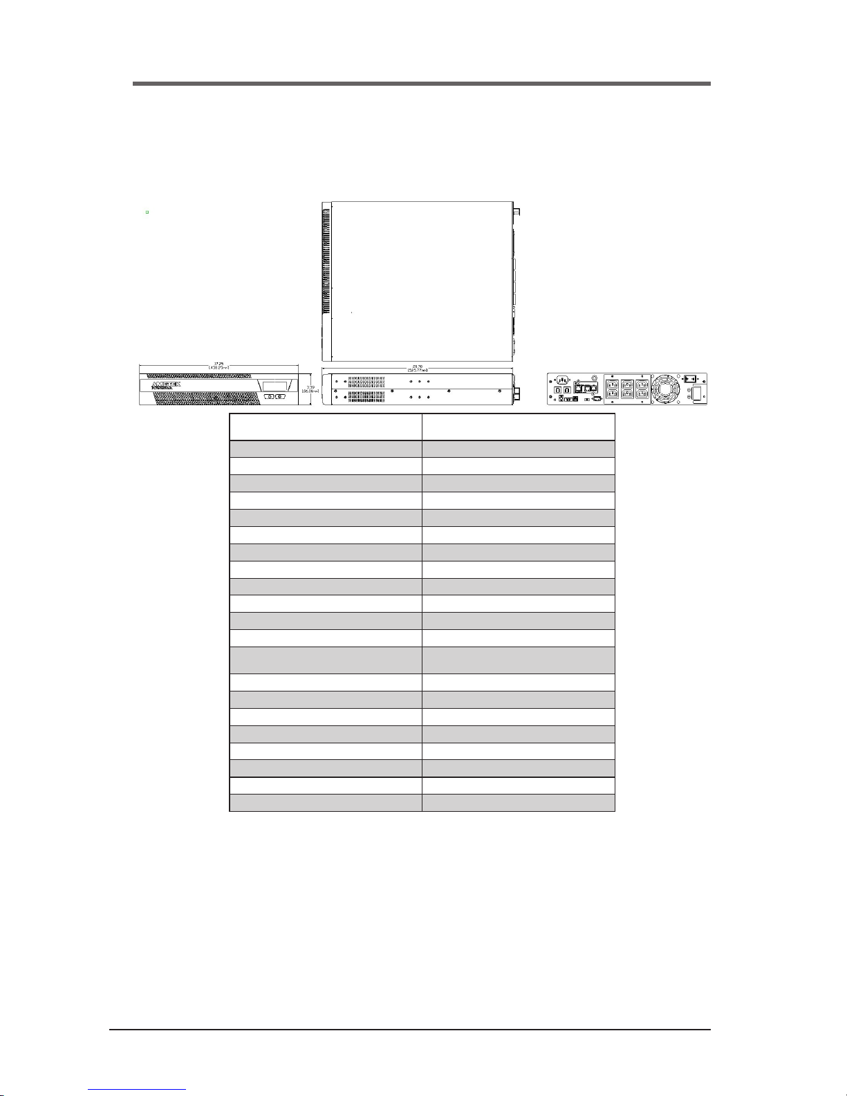
44
A01-00104 Rev A
Security II Rackmount UPM Specications
International 1000 VA Models - Medical
MODEL NUMBER
PART NUMBER
ABCE1002-22RMED
59100-28R
Type Medical Grade
Power Rating (VA/Watts) 1000 / 900
Inverter Waveform Low Distortion Sine Wave
Transfer Time 4 ms. Typical
Frequency 50 / 60 Hz.
BTU/Hr. 304
T.H.D. w/100% Resistive Load <4% On Battery
Online Efciency (w/o Charger) 91%
Input Voltage 230
Input Current 6.25 Amps
Output Voltage 230
Output Current (VA/Watts) 4.35 / 3.90 Amps
Input Voltage Range
(w/o Using Battery)
185 to 276 Volts
Output Regulation (On Mains) ± 10%
Output Regulation (On Battery) ± 5%
Backup Time at Full Load (0.7 P.F.) 10 Minutes
Floor Mountable Yes (Optional)
Communications Interface DB9, USB (SNMP Optional)
Shipping Weight (lbs/kg) 65 lbs / 29 kg
Dimensions (in/mm) L x W x H 20.7 x 17.25 x 3.39 / 525.77 x 438.23 x 86
Output Receptacles 6 IEC320-C13
Security II Rackmount UPM Specications
International 1000 VA Models - Medical
Page 45

45
A01-00104 Rev A
Security II Rackmount UPM Specications
International 1000 VA Models - Medical
Front Panel Controls
• Power On/Off
• Test
• Load Level LED Gauge
• Battery Charge LED Gauge
• Voltage Manager Boost LED
• Voltage Output On LED
• Voltage Manager Buck LED
• On Battery LED
• Replace Battery LED
• Overload LED
• Fault Code LED
• System Over Temperature LED
Rear Panel Information and Controls
• 6 Foot Power Cord with IEC320 Plug
• Integrated Switched Power Distribution Unit
(Requires SNMP / Web Card)
• Conguration Manager DIP Switches
• Communications Manager DB9 Port, USB Port
• Circuit Breaker (AC and DC)
• AC Inlet Module
• Communication Option Slot: SNMP / Web Card, Isolated
Relay Contacts Card, or Remote Off Card
• DC External Battery Cabinet Connector
• Fan (Forced Cooling)
Internal Batteries
• User Hot-Swappable (See Instruction Manual)
• Type: 12 Volt, High Rate 23W
• Quantity: 4 Batteries
• Recharge Time: 6 Hours to 80%, 24 Hours to Full Charge
(For Internal Batteries Only)
Environmental
• Temperature: 0 - +40℃(32 to 104℉) Operating
-20 to 60℃(-40 to 140℉) Shipment/
Storage
• Humidity: 5 to 90% Non-Condensing (Operating,
Shipment/Storage)
• Altitude: 3,000m (10,000 ft) max. Operating;
12,000m (40,000 ft) max. Shipment/Storage
Safety Agency and EMC Compliance:
All Units are Listed by UL and Marked With the UL/cUL Marking
Standard UPM:
Products Listed to:
• UL, IEC62042, CE Mark with CB Report
Medical UPM:
Products Listed To:
• UL60601-1 2nd and 3rd Edition, CE Mark with CB Report
• CSA 22.2 No. 601.1-M89
• CSA 22.2 No. 107-1-M91
• CSA 22.2 Nos. 0-M1982
• CSA 22.2 Nos. 0.4-M1982
Products in Compliance with:
• FCC-Part 15, Subpart B, Sections 15.107b & 15.109b
Class A Digital Device*
• CISPR11:2009, A1; 2010, Class A*
• EN60601-1-2 : 2007
*Note: Class B is Available as an Option
Please Consult Your Powervar Sales Representative
RoHS Compliance:
All Products (Standard and Medical) are RoHS Compliant
1000 VA MODELS TYPICAL RUN-TIMES (MINs)
10%
(90W)
20%
(180W)
30%
(270W)
40%
(360W)
50%
(450W)
60%
(540W)
70%
(630W)
80%
(720W)
90%
(810W)
100%
(900W)
Internal Batteries Only 105 52 30 20 15 12 10 8 6 5
Internal + 1) E4804-12 585 292 180 120 90 72 66 53 41 35
Internal + 2) E4804-12 1065 532 330 220 165 132 122 98 76 65
Internal + 3) E4804-12 1545 772 480 320 240 192 178 143 111 95
Internal + 4) E4804-12 2025 1012 630 420 315 252 234 188 146 125
Internal + 5) E4804-12 2505 1252 780 520 390 312 290 233 181 155
Internal + 6) E4804-12 2985 1492 930 620 465 372 346 278 216 185
Internal + 7) E4804-12 3465 1732 1080 720 540 432 402 323 251 215
Internal + 8) E4804-12 3945 1972 1230 820 615 492 458 368 286 245
NOISE REJECTION-ISOLATION: With unit under power and an ANSI/IEEE C62.41Cat. A pulse applied either normal or common mode at the input, the noise
output voltage will be less than 10V normal mode and less than 0.5V common mode in all four quadrants (CM-NM, NM-NM, CM-CM, NM-CM).
SURGE VOLTAGE WITHSTAND CAPABILITY: Tested under power to ANSI/IEEE C62.41 Cat. A & B (formerly IEEE587-1980). Cat. A - 6000V @ 200 amps, 0.5
usec risetime, 100 kHZ decay, Cat. B - 6000V @ 500 amps, 0.5 usec risetime, 100 kHZ decay.
Warranty/Support: Powervar warrants the electronics and transformers used in its uninterruptible power managers to be free from defects in materials and work-
manship for a period of ve years from the date of shipment. Batteries are warranted for a period of two years from the date of shipment. For service or support on
any Powervar product, please contact Powervar Technical Support at (800) 369-7179 or visit the Powervar website at www.powervar.com.
Battery Life Disclaimer: Powervar’s standard battery warranty applies only to UPS and UPM products which are continuously connected to AC mains power,
except during utility power outages. Products which are regularly and intentionally disconnected from AC mains power will experience battery discharge/charge
cycles potentially far more numerous than those for which the battery was designed. As a result, products used in such applications will experience substantially
reduced battery life. For that reason, Powervar’s standard battery warranty does not apply for applications in which the UPS or UPM product is regularly and
intentionally disconnected from AC mains power. Powervar UPS and UPM products used in such applications shall receive a 90 day warranty on batteries.
Security II Rackmount UPM Specications
International 1000 VA Models - Medical
Page 46

46
A01-00104 Rev A
Security II Rackmount UPM Specications
North American 1440 VA Models - Standard
MODEL NUMBER
PART NUMBER
ABCE1442-11R
58144-01R
ABCE1442-11R
58144-08R
ABCE1442-11R
58144-18R
Type Standard Standard Standard
Power Rating (VA/Watts) 1440 / 1296 1440 / 1296 1440 / 1296
Inverter Waveform Low Distortion Sine Wave Low Distortion Sine Wave Low Distortion Sine Wave
Transfer Time 4 ms. Typical 4 ms. Typical 4 ms. Typical
Frequency 50 / 60 Hz. 50 / 60 Hz. 50 / 60 Hz.
BTU/Hr. 385 385 385
T.H.D. w/100% Resistive Load <4% On Battery <4% On Battery <4% On Battery
Online Efciency (w/o Charger) 92% 92% 92%
Input Voltage 120 120 120
Input Current 12.0 Amps 12.0 Amps 12.0 Amps
Input Voltage Range
(w/o Using Battery)
96 to 144 Volts 96 to 144 Volts 96 to 144 Volts
Output Voltage 120 120 120
Output Current (VA/Watts) 12.0 / 10.8 Amps 12.0 / 10.8 Amps 12.0 / 10.8 Amps
Output Regulation (On Mains) ± 10% ± 10% ± 10%
Output Regulation (On Battery) ± 5% ± 5% ± 5%
Backup Time at Full Load (0.7 P.F.) 5 Minutes 5 Minutes 5 Minutes
Floor Mountable Yes (Optional) Yes (Optional) Yes (Optional)
Communications Interface DB9, USB (SNMP Optional) DB9, USB (SNMP Optional) DB9, USB (SNMP Optional)
Shipping Weight (lbs/kg) 77 lbs / 35 kg 77 lbs / 35 kg 77 lbs / 35 kg
Dimensions (in/mm) L x W x H
20.7 x 17.25 x 3.39 / 525.77 x
438.23 x 86
20.7 x 17.25 x 3.39 / 525.77 x
438.23 x 86
20.7 x 17.25 x 3.39 / 525.77 x
438.23 x 86
Input Plug
6 Ft Power Cord with
NEMA 5-20P Plug
6 Ft Power Cord with
NEMA 5-20P Plug
6 Ft Power Cord with
NEMA 5-15P Plug
Output Receptacles L5-30R 8 NEMA - 5-20R 8 NEMA - 5-20R
PDU Compatible Ye s No No
Security II Rackmount UPM Specications
North American 1440 VA Models - Standard
Page 47

47
A01-00104 Rev A
Security II Rackmount UPM Specications
North American 1440 VA Models - Standard
Front Panel Controls
• Power On/Off
• Test
• Load Level LED Gauge
• Battery Charge LED Gauge
• Voltage Manager Boost LED
• Voltage Output On LED
• Voltage Manager Buck LED
• On Battery LED
• Replace Battery LED
• Overload LED
• Fault Code LED
• System Over Temperature LED
Rear Panel Information and Controls
• Integrated Switched Power Distribution Unit
(Requires SNMP / Web Card)
• Conguration Manager DIP Switches
• Communications Manager DB9 Port, USB Port
• Circuit Breaker (AC and DC)
• AC Inlet Module
• Communication Option Slot: SNMP / Web Card, Isolated
Relay Contacts Card, or Remote Off Card
• DC External Battery Cabinet Connector
• Fan (Forced Cooling)
Internal Batteries
• User Hot-Swappable (See Instruction Manual)
• Type: 12 Volt, High Rate 23W
• Quantity: 4 Batteries
• Recharge Time: 6 Hours to 80%, 24 Hours to Full Charge
(For Internal Batteries Only)
Environmental
• Temperature: 0 - +40℃(32 to 104℉) Operating
-20 to 60℃(-40 to 140℉) Shipment/
Storage
• Humidity: 5 to 90% Non-Condensing (Operating,
Shipment/Storage)
• Altitude: 3,000m (10,000 ft) max. Operating;
12,000m (40,000 ft) max. Shipment/Storage
Safety Agency and EMC Compliance:
All Units are Listed by UL and Marked With the UL/cUL Marking
Standard UPM:
Products Listed to:
• UL1778 5th Edition
• CSA 22.2 Nos. 107.3-14
Products in Compliance with:
• FCC-Part 15, Subpart B, Sections 15.107b & 15.109b
Class A Digital Device*
• CISPR11:2009, A1; 2010, Class A*
• IEC61000-4-2, Electrostatic Discharge
• IEC61000-4-3, Radiated Electromagnetic Field Immunity
• IEC61000-4-4, Electrical Fast Transient/Burst Immunity
• IEC61000-4-5, Surge Immunity
• IEC61000-4-6, Immunity to Conducted Radio Frequency
Disturbances
• IEC61000-4-8, Power Frequency Magnetic Field Immunity
• IEC61000-4-11, Voltage Dips, Short Interruptions and
Voltage Variations
*Note: Class B is Available as an Option
Please Consult Your Powervar Sales Representative
RoHS Compliance:
All Products (Standard and Medical) are RoHS Compliant
1440 VA MODELS TYPICAL RUN-TIMES (MINs)
10% (130W) 20% (259W) 30% (389W) 40% (518W) 50% (648W) 60% (778W) 70% (907W) 80% (1036W) 90% (1166W) 100% (1296W)
Internal Batteries Only 90 38 20 12 9 6 5 4 2.8 2.5
Internal + 1) E4804-12 480 183 110 72 59 51 35 30 25.8 24.5
Internal + 2) E4804-12 870 328 200 132 109 96 65 56 48.8 46.5
Internal + 3) E4804-12 1260 473 290 192 159 141 95 82 71.8 68.5
Internal + 4) E4804-12 1650 618 380 252 209 186 125 108 94.8 90.5
Internal + 5) E4804-12 2040 763 470 312 259 231 155 134 117.8 112.5
Internal + 6) E4804-12 2430 908 560 372 309 276 185 160 140.8 134.5
Internal + 7) E4804-12 2820 1053 650 432 359 321 215 186 163.8 156.5
Internal + 8) E4804-12 3210 1198 740 492 409 366 245 212 186.8 178.5
NOISE REJECTION-ISOLATION: With unit under power and an ANSI/IEEE C62.41Cat. A pulse applied either normal or common mode at the input, the noise
output voltage will be less than 10V normal mode and less than 0.5V common mode in all four quadrants (CM-NM, NM-NM, CM-CM, NM-CM).
SURGE VOLTAGE WITHSTAND CAPABILITY: Tested under power to ANSI/IEEE C62.41 Cat. A & B (formerly IEEE587-1980). Cat. A - 6000V @ 200 amps, 0.5
usec risetime, 100 kHZ decay, Cat. B - 6000V @ 500 amps, 0.5 usec risetime, 100 kHZ decay.
Warranty/Support: Powervar warrants the electronics and transformers used in its uninterruptible power managers to be free from defects in materials and work-
manship for a period of ve years from the date of shipment. Batteries are warranted for a period of two years from the date of shipment. For service or support on
any Powervar product, please contact Powervar Technical Support at (800) 369-7179 or visit the Powervar website at www.powervar.com.
Battery Life Disclaimer: Powervar’s standard battery warranty applies only to UPS and UPM products which are continuously connected to AC mains power,
except during utility power outages. Products which are regularly and intentionally disconnected from AC mains power will experience battery discharge/charge
cycles potentially far more numerous than those for which the battery was designed. As a result, products used in such applications will experience substantially
reduced battery life. For that reason, Powervar’s standard battery warranty does not apply for applications in which the UPS or UPM product is regularly and
intentionally disconnected from AC mains power. Powervar UPS and UPM products used in such applications shall receive a 90 day warranty on batteries.
Security II Rackmount UPM Specications
North American 1440 VA Models - Standard
Page 48

48
A01-00104 Rev A
Security II Rackmount UPM Specications
North American 1440 VA Models - Standard
MODEL NUMBER
PART NUMBER
ABCE1442-11R
58144-01R
ABCE1442-11R
58144-08R
ABCE1442-11R
58144-18R
Type Standard Standard Standard
Power Rating (VA/Watts) 1440 / 1296 1440 / 1296 1440 / 1296
Inverter Waveform Low Distortion Sine Wave Low Distortion Sine Wave Low Distortion Sine Wave
Transfer Time 4 ms. Typical 4 ms. Typical 4 ms. Typical
Frequency 50 / 60 Hz. 50 / 60 Hz. 50 / 60 Hz.
BTU/Hr. 385 385 385
T.H.D. w/100% Resistive Load <4% On Battery <4% On Battery <4% On Battery
Online Efciency (w/o Charger) 92% 92% 92%
Input Voltage 120 120 120
Input Current 12.0 Amps 12.0 Amps 12.0 Amps
Input Voltage Range
(w/o Using Battery)
96 to 144 Volts 96 to 144 Volts 96 to 144 Volts
Output Voltage 120 120 120
Output Current (VA/Watts) 12.0 / 10.8 Amps 12.0 / 10.8 Amps 12.0 / 10.8 Amps
Output Regulation (On Mains) ± 10% ± 10% ± 10%
Output Regulation (On Battery) ± 5% ± 5% ± 5%
Backup Time at Full Load (0.7 P.F.) 5 Minutes 5 Minutes 5 Minutes
Floor Mountable Yes (Optional) Yes (Optional) Yes (Optional)
Communications Interface DB9, USB (SNMP Optional) DB9, USB (SNMP Optional) DB9, USB (SNMP Optional)
Shipping Weight (lbs/kg) 77 lbs / 35 kg 77 lbs / 35 kg 77 lbs / 35 kg
Dimensions (in/mm) L x W x H
20.7 x 17.25 x 3.39 / 525.77 x
438.23 x 86
20.7 x 17.25 x 3.39 / 525.77 x
438.23 x 86
20.7 x 17.25 x 3.39 / 525.77 x
438.23 x 86
Input Plug
6 Ft Power Cord with
NEMA 5-20P Plug
6 Ft Power Cord with
NEMA 5-20P Plug
6 Ft Power Cord with
NEMA 5-15P Plug
Output Receptacles L5-30R 8 NEMA - 5-20R 8 NEMA - 5-20R
PDU Compatible Ye s No No
Security II Rackmount UPM Specications
North American 1440 VA Models - Medical
Page 49

49
A01-00104 Rev A
Security II Rackmount UPM Specications
North American 1440 VA Models - Standard
Front Panel Controls
• Power On/Off
• Test
• Load Level LED Gauge
• Battery Charge LED Gauge
• Voltage Manager Boost LED
• Voltage Output On LED
• Voltage Manager Buck LED
• On Battery LED
• Replace Battery LED
• Overload LED
• Fault Code LED
• System Over Temperature LED
Rear Panel Information and Controls
• Integrated Switched Power Distribution Unit
(Requires SNMP / Web Card)
• Conguration Manager DIP Switches
• Communications Manager DB9 Port, USB Port
• Circuit Breaker (AC and DC)
• AC Inlet Module
• Communication Option Slot: SNMP / Web Card, Isolated
Relay Contacts Card, or Remote Off Card
• DC External Battery Cabinet Connector
• Fan (Forced Cooling)
Internal Batteries
• User Hot-Swappable (See Instruction Manual)
• Type: 12 Volt, High Rate 23W
• Quantity: 4 Batteries
• Recharge Time: 6 Hours to 80%, 24 Hours to Full Charge
(For Internal Batteries Only)
Environmental
• Temperature: 0 - +40℃(32 to 104℉) Operating
-20 to 60℃(-40 to 140℉) Shipment/
Storage
• Humidity: 5 to 90% Non-Condensing (Operating,
Shipment/Storage)
• Altitude: 3,000m (10,000 ft) max. Operating;
12,000m (40,000 ft) max. Shipment/Storage
Safety Agency and EMC Compliance:
All Units are Listed by UL and Marked With the UL/cUL Marking
Standard UPM:
Products Listed to:
• UL1778 5th Edition
• CSA 22.2 Nos. 107.3-14
Products in Compliance with:
• FCC-Part 15, Subpart B, Sections 15.107b & 15.109b
Class A Digital Device*
• CISPR11:2009, A1; 2010, Class A*
• IEC61000-4-2, Electrostatic Discharge
• IEC61000-4-3, Radiated Electromagnetic Field Immunity
• IEC61000-4-4, Electrical Fast Transient/Burst Immunity
• IEC61000-4-5, Surge Immunity
• IEC61000-4-6, Immunity to Conducted Radio Frequency
Disturbances
• IEC61000-4-8, Power Frequency Magnetic Field Immunity
• IEC61000-4-11, Voltage Dips, Short Interruptions and
Voltage Variations
*Note: Class B is Available as an Option
Please Consult Your Powervar Sales Representative
RoHS Compliance:
All Products (Standard and Medical) are RoHS Compliant
1440 VA MODELS TYPICAL RUN-TIMES (MINs)
10% (130W) 20% (259W) 30% (389W) 40% (518W) 50% (648W) 60% (778W) 70% (907W) 80% (1036W) 90% (1166W) 100% (1296W)
Internal Batteries Only 90 38 20 12 9 6 5 4 2.8 2.5
Internal + 1) E4804-12 480 183 110 72 59 51 35 30 25.8 24.5
Internal + 2) E4804-12 870 328 200 132 109 96 65 56 48.8 46.5
Internal + 3) E4804-12 1260 473 290 192 159 141 95 82 71.8 68.5
Internal + 4) E4804-12 1650 618 380 252 209 186 125 108 94.8 90.5
Internal + 5) E4804-12 2040 763 470 312 259 231 155 134 117.8 112.5
Internal + 6) E4804-12 2430 908 560 372 309 276 185 160 140.8 134.5
Internal + 7) E4804-12 2820 1053 650 432 359 321 215 186 163.8 156.5
Internal + 8) E4804-12 3210 1198 740 492 409 366 245 212 186.8 178.5
NOISE REJECTION-ISOLATION: With unit under power and an ANSI/IEEE C62.41Cat. A pulse applied either normal or common mode at the input, the noise
output voltage will be less than 10V normal mode and less than 0.5V common mode in all four quadrants (CM-NM, NM-NM, CM-CM, NM-CM).
SURGE VOLTAGE WITHSTAND CAPABILITY: Tested under power to ANSI/IEEE C62.41 Cat. A & B (formerly IEEE587-1980). Cat. A - 6000V @ 200 amps, 0.5
usec risetime, 100 kHZ decay, Cat. B - 6000V @ 500 amps, 0.5 usec risetime, 100 kHZ decay.
Warranty/Support: Powervar warrants the electronics and transformers used in its uninterruptible power managers to be free from defects in materials and work-
manship for a period of ve years from the date of shipment. Batteries are warranted for a period of two years from the date of shipment. For service or support on
any Powervar product, please contact Powervar Technical Support at (800) 369-7179 or visit the Powervar website at www.powervar.com.
Battery Life Disclaimer: Powervar’s standard battery warranty applies only to UPS and UPM products which are continuously connected to AC mains power,
except during utility power outages. Products which are regularly and intentionally disconnected from AC mains power will experience battery discharge/charge
cycles potentially far more numerous than those for which the battery was designed. As a result, products used in such applications will experience substantially
reduced battery life. For that reason, Powervar’s standard battery warranty does not apply for applications in which the UPS or UPM product is regularly and
intentionally disconnected from AC mains power. Powervar UPS and UPM products used in such applications shall receive a 90 day warranty on batteries.
Security II Rackmount UPM Specications
North American 1440 VA Models - Medical
Page 50

50
A01-00104 Rev A
Security II Rackmount UPM Specications
North American 1440 VA Models - Medical
MODEL NUMBER
PART NUMBER
ABCE1442-11RMED
58144-21R
ABCE1442-11RMED
58144-28R
Type Medical Grade Medical Grade
Power Rating (VA/Watts) 1440 / 1296 1440 / 1296
Inverter Waveform Low Distortion Sine Wave Low Distortion Sine Wave
Transfer Time 4 ms. Typical 4 ms. Typical
Frequency 50 / 60 Hz. 50 / 60 Hz.
BTU/Hr. 385 385
T.H.D. w/100% Resistive Load <4% On Battery <4% On Battery
Online Efciency (w/o Charger) 92% 92%
Input Voltage 120 120
Input Current 12.0 Amps 12.0 Amps
Input Voltage Range
(w/o Using Battery)
96 to 144 Volts 96 to 144 Volts
Output Voltage 120 120
Output Current (VA/Watts) 12.0 / 10.8 Amps 12.0 / 10.8 Amps
Output Regulation (On Mains) ± 10% ± 10%
Output Regulation (On Battery) ± 5% ± 5%
Backup Time at Full Load (0.7 P.F.) 5 Minutes 5 Minutes
Floor Mountable Yes (Optional) Yes (Optional)
Communications Interface DB9, USB (SNMP Optional) DB9, USB (SNMP Optional)
Shipping Weight (lbs/kg) 77 lbs / 35 kg 77 77 lbs / 35 kg
Dimensions (in/mm) L x W x H 20.7 x 17.25 x 3.39 / 525.77 x 438.23 x 86 20.7 x 17.25 x 3.39 / 525.77 x 438.23 x 86
input plug
6 Ft Power Cord with NEMA 5-20P Hospital
Grade Plug
6 Ft Power Cord with NEMA 5-20P Hospital
Grade Plug
Output Receptacles L5-30R (2) NEMA - 5-20R (HG)
PDU Compatible Yes No
Security II Rackmount UPM Specications
International 1440 VA Models - Medical
Page 51

51
A01-00104 Rev A
Security II Rackmount UPM Specications
North American 1440 VA Models - Medical
Front Panel Controls
• Power On/Off
• Test
• Load Level LED Gauge
• Battery Charge LED Gauge
• Voltage Manager Boost LED
• Voltage Output On LED
• Voltage Manager Buck LED
• On Battery LED
• Replace Battery LED
• Overload LED
• Fault Code LED
• System Over Temperature LED
Rear Panel Information and Controls
• Integrated Switched Power Distribution Unit
(Requires SNMP / Web Card)
• Conguration Manager DIP Switches
• Communications Manager DB9 Port, USB Port
• Circuit Breaker (AC and DC)
• AC Inlet Module
• Communication Option Slot: SNMP / Web Card, Isolated
Relay Contacts Card, or Remote Off Card
• DC External Battery Cabinet Connector
• Fan (Forced Cooling)
Internal Batteries
• User Hot-Swappable (See Instruction Manual)
• Type: 12 Volt, High Rate 23W
• Quantity: 4 Batteries
• Recharge Time: 6 Hours to 80%, 24 Hours to Full Charge
(For Internal Batteries Only)
Environmental
• Temperature: 0 - +40℃(32 to 104℉) Operating
-20 to 60℃(-40 to 140℉) Shipment/
Storage
• Humidity: 5 to 90% Non-Condensing (Operating,
Shipment/Storage)
• Altitude: 3,000m (10,000 ft) max. Operating;
12,000m (40,000 ft) max. Shipment/Storage
Safety Agency and EMC Compliance:
All Units are Listed by UL and Marked With the UL/cUL Marking
Medical UPM:
• UL60601-1 2nd and 3rd Edition, CE Mark with CB Report
• CSA 22.2 No. 601.1-M89
• CSA 22.2 No. 107-1-M91
• CSA 22.2 Nos. 0-M1982
• CSA 22.2 Nos. 0.4-M1982
Products in Compliance with:
• FFCC-Part 15, Subpart B, Sections 15.107b & 15.109b
Class A Digital Device*
• CISPR11:2009, A1; 2010, Class A*
• EN60601-1-2 : 2007
*Note: Class B is Available as an Option
Please Consult Your Powervar Sales Representative
RoHS Compliance:
All Products (Standard and Medical) are RoHS Compliant
1440 VA MODELS TYPICAL RUN-TIMES (MINs)
10% (130W) 20% (259W) 30% (389W) 40% (518W) 50% (648W) 60% (778W) 70% (907W) 80% (1036W) 90% (1166W) 100% (1296W)
Internal Batteries Only 90 38 20 12 9 6 5 4 2.8 2.5
Internal + 1) E4804-12 480 183 110 72 59 51 35 30 25.8 24.5
Internal + 2) E4804-12 870 328 200 132 109 96 65 56 48.8 46.5
Internal + 3) E4804-12 1260 473 290 192 159 141 95 82 71.8 68.5
Internal + 4) E4804-12 1650 618 380 252 209 186 125 108 94.8 90.5
Internal + 5) E4804-12 2040 763 470 312 259 231 155 134 117.8 112.5
Internal + 6) E4804-12 2430 908 560 372 309 276 185 160 140.8 134.5
Internal + 7) E4804-12 2820 1053 650 432 359 321 215 186 163.8 156.5
Internal + 8) E4804-12 3210 1198 740 492 409 366 245 212 186.8 178.5
NOISE REJECTION-ISOLATION: With unit under power and an ANSI/IEEE C62.41Cat. A pulse applied either normal or common mode at the input, the noise
output voltage will be less than 10V normal mode and less than 0.5V common mode in all four quadrants (CM-NM, NM-NM, CM-CM, NM-CM).
SURGE VOLTAGE WITHSTAND CAPABILITY: Tested under power to ANSI/IEEE C62.41 Cat. A & B (formerly IEEE587-1980). Cat. A - 6000V @ 200 amps, 0.5
usec risetime, 100 kHZ decay, Cat. B - 6000V @ 500 amps, 0.5 usec risetime, 100 kHZ decay.
Warranty/Support: Powervar warrants the electronics and transformers used in its uninterruptible power managers to be free from defects in materials and work-
manship for a period of ve years from the date of shipment. Batteries are warranted for a period of two years from the date of shipment. For service or support on
any Powervar product, please contact Powervar Technical Support at (800) 369-7179 or visit the Powervar website at www.powervar.com.
Battery Life Disclaimer: Powervar’s standard battery warranty applies only to UPS and UPM products which are continuously connected to AC mains power,
except during utility power outages. Products which are regularly and intentionally disconnected from AC mains power will experience battery discharge/charge
cycles potentially far more numerous than those for which the battery was designed. As a result, products used in such applications will experience substantially
reduced battery life. For that reason, Powervar’s standard battery warranty does not apply for applications in which the UPS or UPM product is regularly and
intentionally disconnected from AC mains power. Powervar UPS and UPM products used in such applications shall receive a 90 day warranty on batteries.
Security II Rackmount UPM Specications
International 1440 VA Models - Medical
Page 52

52
A01-00104 Rev A
Security II Rackmount UPM Specications
International 1440 VA Models - Standard
MODEL NUMBER
PART NUMBER
ABCE1442-22R
59144-08R
Type Standard
Power Rating (VA/Watts) 1440 / 1296
Inverter Waveform Low Distortion Sine Wave
Transfer Time 4 ms. Typical
Frequency 50 / 60 Hz.
BTU/Hr. 442
T.H.D. w/100% Resistive Load <4% On Battery
Online Efciency (w/o Charger) 91%
Input Voltage 230
Input Current 8.54 Amps
Output Voltage 230
Output Current (VA/Watts) 6.30 / 5.65 Amps
Input Voltage Range
(w/o Using Battery)
185 to 276 Volts
Output Regulation (On Mains) ± 10%
Output Regulation (On Battery) ± 5%
Backup Time at Full Load (0.7 P.F.) 5 Minutes
Floor Mountable Yes (Optional)
Communications Interface DB9, USB (SNMP Optional)
Shipping Weight (lbs/kg) 77 lbs / 35 kg
Dimensions (in/mm) L x W x H 20.7 x 17.25 x 3.39 / 525.77 x 438.23 x 86
Outlet Receptacles (6) IEC 320-C13
PDU Compatible No
Security II Rackmount UPM Specications
International 1440 VA Models - Standard
Page 53

53
A01-00104 Rev A
Security II Rackmount UPM Specications
International 1440 VA Models - Standard
Front Panel Controls
• Power On/Off
• Test
• Load Level LED Gauge
• Battery Charge LED Gauge
• Voltage Manager Boost LED
• Voltage Output On LED
• Voltage Manager Buck LED
• On Battery LED
• Replace Battery LED
• Overload LED
• Fault Code LED
• System Over Temperature LED
Rear Panel Information and Controls
• 6 Foot Power Cord with IEC320-C14 Plug
• Integrated Switched Power Distribution Unit
(Requires SNMP / Web Card)
• Conguration Manager DIP Switches
• Communications Manager DB9 Port, USB Port
• Circuit Breaker (AC and DC)
• AC Inlet Module
• Communication Option Slot: SNMP / Web Card, Isolated
Relay Contacts Card, or Remote Off Card
• DC External Battery Cabinet Connector
• Fan (Forced Cooling)
Internal Batteries
• User Hot-Swappable (See Instruction Manual)
• Type: 12 Volt, High Rate 23W
• Quantity: 4 Batteries
• Recharge Time: 6 Hours to 80%, 24 Hours to Full Charge
(For Internal Batteries Only)
Environmental
• Temperature: 0 - +40℃(32 to 104℉) Operating
-20 to 60℃(-40 to 140℉) Shipment/
Storage
• Humidity: 5 to 90% Non-Condensing (Operating,
Shipment/Storage)
• Altitude: 3,000m (10,000 ft) max. Operating;
12,000m (40,000 ft) max. Shipment/Storage
Safety Agency and EMC Compliance:
All Units are Listed by UL and Marked with the UL/cUL Marking.
Standard UPM:
Products Listed To:
• UL, IEC62042, CE Mark with CB Report
Products in compliance with:
• FCC-Part 15, Subpart B, Sections 15.107b & 15.109b
• Class A Digital Device*
• CISPR11:2009, A1; 2010, Class A*
• IEC61000-4-2, Electrostatic Discharge
• IEC61000-4-3, Radiated Electromagnetic Field Immunity
• IEC61000-4-4, Electrical Fast Transient/Burst Immunity
• IEC61000-4-5, Surge Immunity
• IEC61000-4-6, Immunity to Conducted Radio Frequency
• Disturbances
• IEC61000-4-8, Power Frequency Magnetic Field Immunity
• IEC61000-4-11, Voltage Dips, Short Interruptions, and
• Voltage Variations
*Note: Class B is Available as an Option
Please Consult Your Powervar Sales Representative
RoHS Compliance:
All Products (Standard and Medical) are RoHS Compliant
1440 VA MODELS TYPICAL RUN-TIMES (MINs)
10% (130W) 20% (259W) 30% (389W) 40% (518W) 50% (648W) 60% (778W) 70% (907W) 80% (1036W) 90% (1166W) 100% (1296W)
Internal Batteries Only 90 38 20 12 9 6 5 4 2.8 2.5
Internal + 1) E4804-12 480 183 110 72 59 51 35 30 25.8 24.5
Internal + 2) E4804-12 870 328 200 132 109 96 65 56 48.8 46.5
Internal + 3) E4804-12 1260 473 290 192 159 141 95 82 71.8 68.5
Internal + 4) E4804-12 1650 618 380 252 209 186 125 108 94.8 90.5
Internal + 5) E4804-12 2040 763 470 312 259 231 155 134 117.8 112.5
Internal + 6) E4804-12 2430 908 560 372 309 276 185 160 140.8 134.5
Internal + 7) E4804-12 2820 1053 650 432 359 321 215 186 163.8 156.5
Internal + 8) E4804-12 3210 1198 740 492 409 366 245 212 186.8 178.5
NOISE REJECTION-ISOLATION: With unit under power and an ANSI/IEEE C62.41Cat. A pulse applied either normal or common mode at the input, the noise
output voltage will be less than 10V normal mode and less than 0.5V common mode in all four quadrants (CM-NM, NM-NM, CM-CM, NM-CM).
SURGE VOLTAGE WITHSTAND CAPABILITY: Tested under power to ANSI/IEEE C62.41 Cat. A & B (formerly IEEE587-1980). Cat. A - 6000V @ 200 amps, 0.5
usec risetime, 100 kHZ decay, Cat. B - 6000V @ 500 amps, 0.5 usec risetime, 100 kHZ decay.
Warranty/Support: Powervar warrants the electronics and transformers used in its uninterruptible power managers to be free from defects in materials and work-
manship for a period of ve years from the date of shipment. Batteries are warranted for a period of two years from the date of shipment. For service or support on
any Powervar product, please contact Powervar Technical Support at (800) 369-7179 or visit the Powervar website at www.powervar.com.
Battery Life Disclaimer: Powervar’s standard battery warranty applies only to UPS and UPM products which are continuously connected to AC mains power,
except during utility power outages. Products which are regularly and intentionally disconnected from AC mains power will experience battery discharge/charge
cycles potentially far more numerous than those for which the battery was designed. As a result, products used in such applications will experience substantially
reduced battery life. For that reason, Powervar’s standard battery warranty does not apply for applications in which the UPS or UPM product is regularly and
intentionally disconnected from AC mains power. Powervar UPS and UPM products used in such applications shall receive a 90 day warranty on batteries.
Security II Rackmount UPM Specications
International 1440 VA Models - Standard
Page 54

54
A01-00104 Rev A
Security II Rackmount UPM Specications
International 1440 VA Models - Medical
MODEL NUMBER
PART NUMBER
ABCE1442-22RMED
59144-28R
Type Medical Grade
Power Rating (VA/Watts) 1440 / 1296
Inverter Waveform Low Distortion Sine Wave
Transfer Time 4 ms. Typical
Frequency 50 / 60 Hz.
BTU/Hr. 437
T.H.D. w/100% Resistive Load <4% On Battery
Online Efciency (w/o Charger) 91%
Input Voltage 230
Input Current 8.54 Amps
Output Voltage 230
Output Current (VA/Watts) 6.30 / 5.65 Amps
Input Voltage Range
(w/o Using Battery)
185 to 276 Volts
Output Regulation (On Mains) ± 10%
Output Regulation (On Battery) ± 5%
Backup Time at Full Load (0.7 P.F.) 5 Minutes
Floor Mountable Yes (Optional)
Communications Interface DB9, USB (SNMP Optional)
Shipping Weight (lbs/kg) 77 lbs / 35 kg
Dimensions (in/mm) L x W x H 20.7 x 17.25 x 3.39 / 525.77 x 438.23 x 86
Output Receptacles 6 IEC320-C13
PDU Compatible No
Security II Rackmount UPM Specications
International 1440 VA Models - Medical
Page 55

55
A01-00104 Rev A
Security II Rackmount UPM Specications
International 1440 VA Models - Medical
Front Panel Controls
• Power On/Off
• Test
• Load Level LED Gauge
• Battery Charge LED Gauge
• Voltage Manager Boost LED
• Voltage Output On LED
• Voltage Manager Buck LED
• On Battery LED
• Replace Battery LED
• Overload LED
• Fault Code LED
• System Over Temperature LED
Rear Panel Information and Controls
• 6 Foot Power Cord with IEC320-C14 Plug
• Integrated Switched Power Distribution Unit
(Requires SNMP / Web Card)
• Conguration Manager DIP Switches
• Communications Manager DB9 Port, USB Port
• Circuit Breaker (AC and DC)
• AC Inlet Module
• Communication Option Slot: SNMP / Web Card, Isolated
Relay Contacts Card, or Remote Off Card
• DC External Battery Cabinet Connector
• Fan (Forced Cooling)
Internal Batteries
• User Hot-Swappable (See Instruction Manual)
• Type: 12 Volt, High Rate 23W
• Quantity: 4 Batteries
• Recharge Time: 6 Hours to 80%, 24 Hours to Full Charge
(For Internal Batteries Only)
Environmental
• Temperature: 0 - +40℃(32 to 104℉) Operating
-20 to 60℃(-40 to 140℉) Shipment/
Storage
• Humidity: 5 to 90% Non-Condensing (Operating,
Shipment/Storage)
• Altitude: 3,000m (10,000 ft) max. Operating;
12,000m (40,000 ft) max. Shipment/Storage
Safety Agency and EMC Compliance:
All Units are Listed by UL and Marked With the UL/cUL Marking
Standard UPM:
Products Listed to:
• UL, IEC62042, CE Mark with CB Report
Products in Compliance with:
• FCC-Part 15, Subpart B, Sections 15.107b & 15.109b
• Class A Digital Device*
• CISPR11:2009, A1; 2010, Class A*
• IEC61000-4-2, Electrostatic Discharge
• IEC61000-4-3, Radiated Electromagnetic Field Immunity
• IEC61000-4-4, Electrical Fast Transient/Burst Immunity
• IEC61000-4-5, Surge Immunity
• IEC61000-4-6, Immunity to Conducted Radio Frequency
• Disturbances
• IEC61000-4-8, Power Frequency Magnetic Field Immunity
• IEC61000-4-11, Voltage Dips, Short Interruptions, and
• Voltage Variations
*Note: Class B is Available as an Option
Please Consult Your Powervar Sales Representative
RoHS Compliance:
All Products (Standard and Medical) are RoHS Compliant
1440 VA MODELS TYPICAL RUN-TIMES (MINs)
10% (130W) 20% (259W) 30% (389W) 40% (518W) 50% (648W) 60% (778W) 70% (907W) 80% (1036W) 90% (1166W) 100% (1296W)
Internal Batteries Only 90 38 20 12 9 6 5 4 2.8 2.5
Internal + 1) E4804-12 480 183 110 72 59 51 35 30 25.8 24.5
Internal + 2) E4804-12 870 328 200 132 109 96 65 56 48.8 46.5
Internal + 3) E4804-12 1260 473 290 192 159 141 95 82 71.8 68.5
Internal + 4) E4804-12 1650 618 380 252 209 186 125 108 94.8 90.5
Internal + 5) E4804-12 2040 763 470 312 259 231 155 134 117.8 112.5
Internal + 6) E4804-12 2430 908 560 372 309 276 185 160 140.8 134.5
Internal + 7) E4804-12 2820 1053 650 432 359 321 215 186 163.8 156.5
Internal + 8) E4804-12 3210 1198 740 492 409 366 245 212 186.8 178.5
NOISE REJECTION-ISOLATION: With unit under power and an ANSI/IEEE C62.41Cat. A pulse applied either normal or common mode at the input, the noise
output voltage will be less than 10V normal mode and less than 0.5V common mode in all four quadrants (CM-NM, NM-NM, CM-CM, NM-CM).
SURGE VOLTAGE WITHSTAND CAPABILITY: Tested under power to ANSI/IEEE C62.41 Cat. A & B (formerly IEEE587-1980). Cat. A - 6000V @ 200 amps,
Cat. B - 6000V @ 500 amps..
Warranty/Support: Powervar warrants the electronics and transformers used in its uninterruptible power managers to be free from defects in materials and work-
manship for a period of ve years from the date of shipment. Batteries are warranted for a period of two years from the date of shipment. For service or support on
any Powervar product, please contact Powervar Technical Support at (800) 369-7179 or visit the Powervar website at www.powervar.com.
Battery Life Disclaimer: Powervar’s standard battery warranty applies only to UPS and UPM products which are continuously connected to AC mains power,
except during utility power outages. Products which are regularly and intentionally disconnected from AC mains power will experience battery discharge/charge
cycles potentially far more numerous than those for which the battery was designed. As a result, products used in such applications will experience substantially
reduced battery life. For that reason, Powervar’s standard battery warranty does not apply for applications in which the UPS or UPM product is regularly and
intentionally disconnected from AC mains power. Powervar UPS and UPM products used in such applications shall receive a 90 day warranty on batteries.
Security II Rackmount UPM Specications
International 1440 VA Models - Medical
Page 56

56
A01-00104 Rev A
Security II UPM Specifications
North American Models ABCE2202-11R
ABCE2202-11R
58220-08R
Typ e Standard
Power Rating (VA/Watts) 2200 / 1980
Inverter Waveform
Low Distortion Sine Wave
Transfer Time
4 ms. Typical
Frequency
50 / 60 Hz.
BTU/Hr.
355
T.H.D. Max. w/100% Resistive Load <4% On Battery
Online Efficiency (w/o Charger) 95%
Input Voltage
120
Input Current
24.0 Amps
Output Voltage
120
Output Current (VA/Watts)
18.5 / 16.5 Amps
Input Voltage Range (w/o Using Battery)
96 to 144 Volts
Output Regulation (On Mains)
+ 10%
Output Regulation (On Battery)
+ 5%
Backup Time at Full Load (0.7 P.F)
8 Minutes
Floor mountable
Yes (Optional)
Communications Interface
DB9, USB (SNMP Optional)
Shipping Weight (lbs./kg)
134 lbs. / 61 kg
Dimensions (in/mm) L x W x H
20.7 x 17.26 x 6.89 /
525.77 x 438.23 x 175.00
Output Receptacle
(8) NEMA 5-20R and (1) NEMA L5-30R Receptacles
PDU Compatible
Yes
Security II UPM Specications
North American Models ABCE2202-11R
Page 57

57
A01-00104 Rev A
Front Panel Controls
Power On/Off
Test
Load Level LED Gauge
Battery Charge LED Gauge
Voltage Manager Boost LED
Voltage Output On LED
Voltage Manager Buck LED
On Battery LED
Replace Battery LED
Overload LED
Fault Code LED
System Over Temperature LED
Rear Panel Information and Controls
6 Foot Power Cord with NEMA L5-30P Plug
Configuration Manager DIP Switches
Communications Manager DB9 Port, USB Port
Circuit Breaker
AC Inlet Module
SNMP Slot (Contact Factory)
Internal Batteries
User Hot-Swappable (See Instruction Manual)
Type: 12 Volt, High Rate 23W
Quantity: 8 Batteries
Recharge Time: 8 Hours to 80%, 24 Hours to Full Charge
Environmental
Temperature: 0 - +40
0
C (32 to 1040F) Operating
-20 to 60
0
C (-40 to 1400 F) Shipment/
Storage
Humidity: 5 to 90% Non-Condensing (Operating,
Shipment/Storage)
Altitude: 3,000m (10,000 ft) max. Operating;
12,000m (40,000 ft) max. Shipment/Storage.
Safety Agency and EMC Compliance:
All Units are Listed by UL and Marked with the UL/cUL Marking.
Standard UPM:
Products Listed To:
UL1778 5th Edition
CSA 22.2 Nos. 107.3-14
Products in compliance with:
FCC-Part 15, Subpart B, Sections 15.107b & 15.109b
Class A Digital Device*
CISPR11:2009, A1; 2010, Class A*
IEC61000-4-2, Electrostatic Discharge
IEC61000-4-3, Radiated Electromagnetic Field Immunity
IEC61000-4-4, Electrical Fast Transient/Burst Immunity
IEC61000-4-5, Surge Immunity
IEC61000-4-6, Immunity to Conducted Radio Frequency
Disturbances
IEC61000-4-8, Power Frequency Magnetic Field Immunity
IEC61000-4-11, Voltage Dips, Short Interruptions, and
Voltage Variations
*Note: Class B is Available as an Option
Please Consult Your Powervar Sales Representative
2200VA TYPICAL RUN-TIMES (MINs)
10% (198W)
20%
(396W)
30% (594W)
40%
(792W)
50% (990W)
60%
(1188W)
70%
(1386W)
80%
(1584W)
90% (1782W)
100%
(1980W)
Internal Baeries Only 95 45 30 19 14 10.5 8 6.5 5.5 4.5
Internal + 1) E4804-12 281 135 85 59 42 32.5 23 19 14.5 12
Internal + 2) E4804-12 467 225 140 99 70 54.5 38 31.5 23.5 19.5
Internal + 3) E4804-12 653 315 195 139 98 76.5 53 44 32.5 27
Internal + 4) E4804-12 839 405 250 179 126 98.5 68 56.5 41.5 34.5
Internal + 5) E4804-12 1025 495 305 219 154 120.5 83 69 50.5 42
Internal + 6) E4804-12 1211 585 360 259 182 142.5 98 81.5 59.5 49.5
Internal + 7) E4804-12 1397 675 415 299 210 164.5 113 94 68.5 57
Internal + 8) E4804-12 1583 765 470 339 238 186.5 128 106.5 77.5 64.5
NOISE REJECTION-ISOLATION: With unit under power and an ANSI/IEEE C62.41Cat. A pulse applied either normal or common mode
at the input, the noise output voltage will be less than 10V normal mode and less than 0.5V common mode in all four quadrants (CM-NM, NMNM, CM-CM, NM-COM).
SURGE VOLTAGE WITHSTAND CAPABILITY: Tested u nder power to ANSI/IEEE C62.41 Cat. A & B (for merl y IEEE587-1980). Cat. A 6000V @ 200 amps, 0.5 usec risetime, 100 kHZ decay, Cat. B - 6000V @ 500 amps, 0.5 usec risetime, 100 kHZ decay.
Warranty/Support: POWERVAR warrants the electronics and transformers used in its uninterruptible power managers to be free from
defects in materials and workmanship for a period of five years from the date of shipment. Batteries are warranted for a period of two years from
the date of shipment. For service or support on any POWERVAR product, please contact POWERVAR Technical Support at (800) 369-7179 or
visit the POWERVAR website at ww.p owerva r.com.
Battery Life Disclaimer: POWERVAR’s standard battery warranty applies only to UPS and UPM products which are continuously connected to
AC mains power, except during utility power outages. Products which are regularly and intentionally disconnected from AC mains power will
experience battery discharge/charge cycles potentially far more numerous than those for which the battery was designed. As a result, products
used in such applications will experience substantially reduced battery life. For that reason, POWERVAR’s standard battery warranty does not
apply for applications in which the UPS or UPM product is regularly and intentionally disconnected from AC mains power. POWERVAR UPS and
UPM products used in such applications shall receive a 90 day warranty on batteries.
Security II UPM Specications
North American Models ABCE2202-11R
Page 58

58
A01-00104 Rev A
Security II UPM Specifications
International Models ABCE2202-22R
ABCE2202-22R
59220-08R
Typ e Standard
Power Rating (VA/Watts) 2200 / 1980
Inverter Waveform
Low Distortion Sine Wave
Transfer Time
4 ms. Typical
Frequency
50 / 60 Hz.
BTU/Hr.
355
T.H.D. Max. w/100% Resistive Load <4% On Battery
Online Efficiency (w/o Charger) 95%
Input Voltage
230
Input Current
16.0 Amps
Output Voltage
230
Output Current (VA/Watts)
9.55 / 8.60 Amps
Input Voltage Range (w/o Using Battery)
185 to 276 Volts
Output Regulation (On Mains)
+ 10%
Output Regulation (On Battery)
+ 5%
Backup Time at Full Load (0.7 P.F)
8 Minutes
Floor Mountable
Yes (Optional)
Communications Interface
DB9, USB (SNMP Optional)
Shipping Weight (lbs./kg)
142 lbs../66.4 kg
Dimensions (in/mm) L x W x H
20.7 x 17.26 x 6.89 /
525.77 x 438.23 x 175.00
Output Receptacle
(8) IEC320 C13 and (1) IEC320 C19 Receptacles
PDU Compatible
No
Security II UPM Specications
International Models ABCE2202-22R
Page 59

59
A01-00104 Rev A
Front Panel Controls
Power On/Off
Test
Load Level LED Gauge
Battery Charge LED Gauge
Voltage Manager Boost LED
Voltage Output On LED
Voltage Manager Buck LED
On Battery LED
Replace Battery LED
Overload LED
Fault Code LED
System Over Temperature LED
Rear Panel Information and Controls
1.8 Meter Power Cord with C20 to C19 IEC300
Configuration Manager DIP Switches
Communications Manager DB9 Port, USB Port
Circuit Breaker
AC Inlet Module
SNMP Slot (Contact Factory)
Internal Batteries
User Hot-Swappable (See Instruction Manual)
Type: 12 Volt, High Rate 23W
Quantity: 8 Batteries
Recharge Time: 8 Hours to 80%, 24 Hours to Full Charge
Environmental
Temperature: 0 - +40
0
C (32 to 1040F) Operating
-20 to 60
0
C (-40 to 1400 F) Shipment/
Storage
Humidity: 5 to 90% Non-Condensing (Operating,
Shipment/Storage)
Altitude: 3,000m (10,000 ft) max. Operating;
12,000m (40,000 ft) max. Shipment/Storage.
Safety Agency and EMC Compliance:
All Units are Listed by UL and Marked with the UL/cUL Marking.
Standard UPM:
Products Listed To:
UL IEC62040, CE Mark with CB Report
Products in compliance with:
FCC-Part 15, Subpart B, Sections 15.107b & 15.109b
Class A Digital Device*
CISPR11:2009, A1; 2010, Class A*
IEC61000-4-2, Electrostatic Discharge
IEC61000-4-3, Radiated Electromagnetic Field Immunity
IEC61000-4-4, Electrical Fast Transient/Burst Immunity
IEC61000-4-5, Surge Immunity
IEC61000-4-6, Immunity to Conducted Radio Frequency
Disturbances
IEC61000-4-8, Power Frequency Magnetic Field Immunity
IEC61000-4-11, Voltage Dips, Short Interruptions, and
Voltage Variations
*Note: Class B is Available as an Option
Please Consult Your Powervar Sales Representative
RoHS Compliance:
All Products (Standard and Medical) are RoHS Compliant
2200VA TYPICAL RUN-TIMES (MINs)
10% (198W) 20 % (396W) 30% (594W) 40% (792W) 50% (990W) 60% (1188W) 70% (1 386W) 80% (158 4W) 90% (1782W )
100%
(1980W)
Internal Baeries Only 95 45 30 19 14 10.5 8 6.5 5.5 4.5
Internal + 1) E4804-12 281 135 85 59 42 32.5 23 19 14.5 12
Internal + 2) E4804-12 467 225 140 99 70 54.5 38 31.5 23.5 19.5
Internal + 3) E4804-12 653 315 195 139 98 76.5 53 44 32.5 27
Internal + 4) E4804-12 839 405 250 179 126 98.5 68 56.5 41.5 34.5
Internal + 5) E4804-12 1025 495 305 219 154 120.5 83 69 50.5 42
Internal + 6) E4804-12 1211 585 360 259 182 142.5 98 81.5 59.5 49.5
Internal + 7) E4804-12 1397 675 415 299 210 164.5 113 94 68.5 57
Internal + 8) E4804-12 1583 765 470 339 238 186.5 128 106.5 77.5 64.5
NOISE REJECTION-ISOLATION: With unit under power and an ANSI/IEEE C62.41Cat. A pulse applied either normal or common mode
at the input, the noise output voltage will be less than 10V normal mode and less than 0.5V common mode in all four quadrants (CM-NM, NMNM, CM-CM, NM-COM).
SURGE VOLTAGE WITHSTAND CAPABILITY: Tested u nder power to ANSI/IEEE C62.41 Cat. A & B (for merl y IEEE587-1980). Cat. A 6000V @ 200 amps, 0.5 usec risetime, 100 kHZ decay, Cat. B - 6000V @ 500 amps, 0.5 usec risetime, 100 kHZ decay.
Warranty/Support: POWERVAR warrants the electronics and transformers used in its uninterruptible power managers to be free from
defects in materials and workmanship for a period of five years from the date of shipment. Batteries are warranted for a period of two years from
the date of shipment. For service or support on any POWERVAR product, please contact POWERVAR Technical Support at (800) 369-7179 or
visit the POWERVAR website at ww.p owerva r.com .
Battery Life Disclaimer: POWERVAR’s standard battery warranty applies only to UPS and UPM products which are continuously connected to
AC mains power, except during utility power outages. Products which are regularly and intentionally disconnected from AC mains power will
experience battery discharge/charge cycles potentially far more numerous than those for which the battery was designed. As a result, products
used in such applications will experience substantially reduced battery life. For that reason, POWERVAR’s standard battery warranty does not
apply for applications in which the UPS or UPM product is regularly and intentionally disconnected from AC mains power. POWERVAR UPS and
UPM products used in such applications shall receive a 90 day warranty on batteries.
Security II UPM Specications
International Models ABCE2202-22R
Page 60

60
A01-00104 Rev A
Security II UPM Specifications
North American Models ABCE3002-21R
MODEL NUMBER
PART NUMBER
ABCE3002-21R
59300-32R
ABCE3002-21R
59300-38R
Typ e Standard Standard
Power Rating (VA/Watts) 2760 / 2484 2760 / 2484
Inverter Waveform
Low Distortion Sine Wave Low Distortion Sine Wave
Transfer Time
4 ms. Typical 4 ms. Typical
Frequency
50 / 60 Hz. 50 / 60 Hz.
BTU/Hr.
446 446
T.H.D. Max. w/100% Resistive Load <4% On Battery <4% On Battery
Online Efficiency (w/o Charger) 95% 95%
Input Voltage
208 230
Input Current
16.0 Amps 16.0 Amps
Output Voltage
230 and 115 230 and 115
Output Current (VA/Watts)
12.0 / 11.5 and 24.0 / 21.6 Amps 12.0 / 11.5 and 24.0 / 21.6 Amps
Input Voltage Range (w/o Using Battery) 166 to 250 Volts 184 to 276 Volts
Output Regulation (On Mains) + 10% + 10%
Output Regulation (On Battery)
+ 5% + 5%
Backup Time at Full Load (0.7 P.F)
6 Minutes 6 Minutes
Floor Mountable
Yes (Optional) Yes (Optional)
Communications Interface
DB9, USB (SNMP Optional) DB9, USB (SNMP Optional)
Shipping Weight (lbs./kg)
142 lbs. / 64.4 kg 1142 lbs. / 64.4 kg
Dimensions (in/mm) L x W x H
20.7 x 17.26 x 6.89 /
525.77 x 438.23 x 175.00
20.7 x 17.26 x 6.89 /
525.77 x 438.23 x 175.00
Output Receptacle
Eight (8) NEMA 5-20 and (1) NEMA
L6-20 Receptacles
Eight (8) NEMA 5-20 and (1) NEMA
L6-20 Receptacles
PDU Compatible
Yes Yes
Security II UPM Specications
North American Models ABCE3002-21R
Page 61

61
A01-00104 Rev A
Front Panel Controls
Power On/Off
Test
Load Level LED Gauge
Battery Charge LED Gauge
Voltage Manager Boost LED
Voltage Output On LED
Voltage Manager Buck LED
On Battery LED
Replace Battery LED
Overload LED
Fault Code LED
System Over Temperature LED
Rear Panel Information and Controls
1.8 Meter Power Cord with C20 to L6-20 Plug
Eight (8) NEMA 5-20R and (1) NEMA L6-20 Receptacles
Configuration Manager DIP Switches
Communications Manager DB9 Port, USB Port
Circuit Breaker
AC Inlet Module
SNMP Slot (Contact Factory)
Internal Batteries
User Hot-Swappable (See Instruction Manual)
Type: 12 Volt, High Rate 23W
Quantity: 8 Batteries
Recharge Time: 8 Hours to 80%, 24 Hours to Full Charge
Environmental
Temperature: 0 - +40
0
C (32 to 1040F) Operating
-20 to 600 C (-40 to 1400 F) Shipment/
Storage
Humidity: 5 to 90% Non-Condensing (Operating,
Shipment/Storage)
Altitude: 3,000m (10,000 ft) max. Operating;
12,000m (40,000 ft) max. Shipment/Storage.
Safety Agency and EMC Compliance:
All Units are Listed by UL and Marked with the UL/cUL Marking.
Standard UPM:
Products Listed To:
UL IEC62040, CE Mark with CB Report
Products in compliance with:
FCC-Part 15, Subpart B, Sections 15.107b & 15.109b
Class A Digital Device*
CISPR11:2009, A1; 2010, Class A*
IEC61000-4-2, Electrostatic Discharge
IEC61000-4-3, Radiated Electromagnetic Field Immunity
IEC61000-4-4, Electrical Fast Transient/Burst Immunity
IEC61000-4-5, Surge Immunity
IEC61000-4-6, Immunity to Conducted Radio Frequency
Disturbances
IEC61000-4-8, Power Frequency Magnetic Field Immunity
IEC61000-4-11, Voltage Dips, Short Interruptions, and
Voltage Variations
*Note: Class B is Available as an Option
Please Consult Your Powervar Sales Representative
3000VA TYPICAL RUN-TIMES (MINs)
10% (248W) 20% (297W) 30% (745W) 40% (993W) 50% ( 1242W) 60% (1490W) 70% (1739W ) 80% ( 1987W) 90% (2235W ) 100% (2484W)
Internal Baeries Only 89 58 20 14 10 7 6 4.8 3.2 3
Internal + 1) E4804-12 239 178 62 42 30 24 16 10.8 9.2 7.5
Internal + 2) E4804-12 389 298 104 70 50 41 26 16.8 15.2 12
Internal + 3) E4804-12 539 418 146 98 70 58 36 22.8 21.2 16.5
Internal + 4) E4804-12 689 538 188 126 90 75 46 28.8 27.2 21
Internal + 5) E4804-12 839 658 230 154 110 92 56 34.8 33.2 25.5
Internal + 6) E4804-12 989 778 272 182 130 109 66 40.8 39.2 30
Internal + 7) E4804-12 1139 898 314 210 150 126 76 46.8 45.2 34.5
Internal + 8) E4804-12 1289 1018 356 238 170 143 86 52.8 51.2 39
NOISE REJECTION-ISOLATION: With unit under power and an ANSI/IEEE C62.41Cat. A pulse applied either normal or common mode
at the input, the noise output voltage will be less than 10V normal mode and less than 0.5V common mode in all four quadrants (CM-NM, NMNM, CM-CM, NM-COM).
SURGE VOLTAGE WITHSTAND CAPABILITY: Tested u nder power to ANSI/IEEE C62.41 Cat. A & B (for merl y IEEE587-1980). Cat. A 6000V @ 200 amps, 0.5 usec risetime, 100 kHZ decay, Cat. B - 6000V @ 500 amps, 0.5 usec risetime, 100 kHZ decay.
Warranty/Support: POWERVAR warrants the electronics and transformers used in its uninterruptible power managers to be free from
defects in materials and workmanship for a period of five years from the date of shipment. Batteries are warranted for a period of two years from
the date of shipment. For service or support on any POWERVAR product, please contact POWERVAR Technical Support at (800) 369-7179 or
visit the POWERVAR website at ww.p owerva r.com.
Battery Life Disclaimer: POWERVAR’s standard battery warranty applies only to UPS and UPM products which are continuously connected to
AC mains power, except during utility power outages. Products which are regularly and intentionally disconnected from AC mains power will
experience battery discharge/charge cycles potentially far more numerous than those for which the battery was designed. As a result, products
used in such applications will experience substantially reduced battery life. For that reason, POWERVAR’s standard battery warranty does not
apply for applications in which the UPS or UPM product is regularly and intentionally disconnected from AC mains power. POWERVAR UPS and
UPM products used in such applications shall receive a 90 day warranty on batteries.
Security II UPM Specications
North American Models ABCE3002-21R
Page 62

62
A01-00104 Rev A
Security II UPM Specifications
International Models ABCE3002-22R
ABCE3002-22R
59300-08R
Typ e Standard
Power Rating (VA/Watts) 2760 / 2484
Inverter Waveform
Low Distortion Sine Wave
Transfer Time
4 ms. Typical
Frequency
50 / 60 Hz.
BTU/Hr.
446
T.H.D. Max. w/100% Resistive Load <4% On Battery
Online Efficiency (w/o Charger) 95%
Input Voltage
230
Input Current
16.0 Amps
Output Voltage
230
Output Current (VA/Watts)
12.0 / 10.8 Amps
Input Voltage Range (w/o Using Battery)
185 to 276 Volts
Output Regulation (On Mains)
+ 10%
Output Regulation (On Battery)
+ 5%
Backup Time at Full Load (0.7 P.F)
6 Minutes
Floor Mountable
Yes (Optional)
Communications Interface
DB9, USB (SNMP Optional)
Shipping Weight (lbs.)
134
Dimensions (in/mm) L x W x H
20.7 x 17.26 x 6.89 /
525.77 x 438.23 x 175.00
Output Receptacle
Eight (8) IEC320 C13 and (1) IEC320 C19 Receptacles
PDU Compatible
No
Security II UPM Specications
International Models ABCE3002-22R
Page 63

63
A01-00104 Rev A
Front Panel Controls
Power On/Off
Test
Load Level LED Gauge
Battery Charge LED Gauge
Voltage Manager Boost LED
Voltage Output On LED
Voltage Manager Buck LED
On Battery LED
Replace Battery LED
Overload LED
Fault Code LED
System Over Temperature LED
Rear Panel Information and Controls
1.8 Meter Power Cord with C20 to C19 IEC320
Configuration Manager DIP Switches
Communications Manager DB9 Port, USB Port
Circuit Breaker
AC Inlet Module
SNMP Slot (Contact Factory)
Internal Batteries
User Hot-Swappable (See Instruction Manual)
Type: 12 Volt, High Rate 23W
Quantity: 8 Batteries
Recharge Time: 8 Hours to 80%, 24 Hours to Full Charge
Environmental
Temperature: 0 - +40
0
C (32 to 1040F) Operating
-20 to 60
0
C (-40 to 1400 F) Shipment/
Storage
Humidity: 5 to 90% Non-Condensing (Operating,
Shipment/Storage)
Altitude: 3,000m (10,000 ft) max. Operating;
12,000m (40,000 ft) max. Shipment/Storage.
Safety Agency and EMC Compliance:
All Units are Listed by UL and Marked with the UL/cUL Marking.
Standard UPM:
Products Listed To:
UL IEC62040, CE Mark with CB Report
Products in compliance with:
FCC-Part 15, Subpart B, Sections 15.107b & 15.109b
Class A Digital Device*
CISPR11:2009, A1; 2010, Class A*
IEC61000-4-2, Electrostatic Discharge
IEC61000-4-3, Radiated Electromagnetic Field Immunity
IEC61000-4-4, Electrical Fast Transient/Burst Immunity
IEC61000-4-5, Surge Immunity
IEC61000-4-6, Immunity to Conducted Radio Frequency
Disturbances
IEC61000-4-8, Power Frequency Magnetic Field Immunity
IEC61000-4-11, Voltage Dips, Short Interruptions, and
Voltage Variations
*Note: Class B is Available as an Option
Please Consult Your Powervar Sales Representative
RoHS Compliance:
All Products (Standard and Medical) are RoHS Compliant
3000VA TYPICAL RUN-TIMES (MINs)
10% (248W) 20% (297W) 30% (745W) 40% (993W) 50% ( 1242W) 60% (1490W) 70% (1739W ) 80% ( 1987W) 90% (2235W ) 100% (2484W)
Internal Baeries Only 89 58 20 14 10 7 6 4.8 3.2 3
Internal + 1) E4804-12 239 178 62 42 30 24 16 10.8 9.2 7.5
Internal + 2) E4804-12 389 298 104 70 50 41 26 16.8 15.2 12
Internal + 3) E4804-12 539 418 146 98 70 58 36 22.8 21.2 16.5
Internal + 4) E4804-12 689 538 188 126 90 75 46 28.8 27.2 21
Internal + 5) E4804-12 839 658 230 154 110 92 56 34.8 33.2 25.5
Internal + 6) E4804-12 989 778 272 182 130 109 66 40.8 39.2 30
Internal + 7) E4804-12 1139 898 314 210 150 126 76 46.8 45.2 34.5
Internal + 8) E4804-12 1289 1018 356 238 170 143 86 52.8 51.2 39
NOISE REJECTION-ISOLATION: With unit under power and an ANSI/IEEE C62.41Cat. A pulse applied either normal or common mode
at the input, the noise output voltage will be less than 10V normal mode and less than 0.5V common mode in all four quadrants (CM-NM, NMNM, CM-CM, NM-COM).
SURGE VOLTAGE WITHSTAND CAPABILITY: Tested u nder power to ANSI/IEEE C62.41 Cat. A & B (for merl y IEEE587-1980). Cat. A 6000V @ 200 amps, 0.5 usec risetime, 100 kHZ decay, Cat. B - 6000V @ 500 amps, 0.5 usec risetime, 100 kHZ decay.
Warranty/Support: POWERVAR warrants the electronics and transformers used in its uninterruptible power managers to be free from
defects in materials and workmanship for a period of five years from the date of shipment. Batteries are warranted for a period of two years from
the date of shipment. For service or support on any POWERVAR product, please contact POWERVAR Technical Support at (800) 369-7179 or
visit the POWERVAR website at ww.p owerva r.com.
Battery Life Disclaimer: POWERVAR’s standard battery warranty applies only to UPS and UPM products which are continuously connected to
AC mains power, except during utility power outages. Products which are regularly and intentionally disconnected from AC mains power will
experience battery discharge/charge cycles potentially far more numerous than those for which the battery was designed. As a result, products
used in such applications will experience substantially reduced battery life. For that reason, POWERVAR’s standard battery warranty does not
apply for applications in which the UPS or UPM product is regularly and intentionally disconnected from AC mains power. POWERVAR UPS and
UPM products used in such applications shall receive a 90 day warranty on batteries.
Security II UPM Specications
International Models ABCE3002-22R
Page 64

64
A01-00104 Rev A
Security II UPM Specifications
North American Models ABCE2202-11R
MODEL NUMBER
P
ART NUMBER
ABCE2202-11R
58220-10R
ABCE2202-11R
58220-38R
Typ e Standard Standard
Power Rating (VA/Watts) 1800/1620 1800/1620
Inverter Waveform
Low Distortion Sine Wave Low Distortion Sine Wave
Transfer Time
4 ms. Typical 4 ms. Typical
Frequency
50 / 60 Hz. 50 / 60 Hz.
BTU/Hr.
355 355
T.H.D. Max. w/100% Resistive Load <4% On Battery <4% On Battery
Online Efficiency (w/o Charger) 95% 95%
Input Voltage
120 120
Input Current
16.0 Amps 16.0 Amps
Output Voltage
120 120
Output Current (VA/Watts)
15.0 / 13.5 Amps 15.0 / 13.5 Amps
Input Voltage Range (w/o Using Batter y)
96 to 144 Volts 96 to 144 Volts
Output Regulation (On Mains)
+ 10% + 10%
Output Regulation (On Battery)
+ 5% + 5%
Backup Time at Full Load (0.7 P.F)
10 Minutes 10 Minutes
Floor mountable
Yes (Optional) Yes (Optional)
Communications Interface
DB9, USB (SNMP Optional) DB9, USB (SNMP Optional)
Shipping Weight (lbs./kg) 134 lbs. / 61 kg 134 lbs. / 61 kg
Dimensions (in/mm) L x W x H
20.7 x 17.26 x 6.89 /
525.77 x 438.23 x 175.00
20.7 x 17.26 x 6.89 /
525.77 x 438.23 x 175.00
Input Plug 5-20P L5-20P
Output Receptacle
Eight (8) NEMA 5-20R and
(1) NEMA L5-30R Receptacles
Eight (8) NEMA 5-20R and
(1) NEMA L5-30R Receptacles
PDU Compatible Yes Yes
Security II UPM Specications
North American Models ABCE2202-11R
Page 65

65
A01-00104 Rev A
Front Panel Controls
Power On/Off
Test
Load Level LED Gauge
Battery Charge LED Gauge
Voltage Manager Boost LED
Voltage Output On LED
Voltage Manager Buck LED
On Battery LED
Replace Battery LED
Overload LED
Fault Code LED
System Over Temperature LED
Rear Panel Information and Controls
Configuration Manager DIP Switches
Communications Manager DB9 Port, USB Port
Circuit Breaker
AC Inlet Module
SNMP Slot (Contact Factory)
Internal Batteries
User Hot-Swappable (See Instruction Manual)
Type: 12 Volt, High Rate 23W
Quantity: 8 Batteries
Recharge Time: 8 Hours to 80%, 24 Hours to Full Charge
Environmental
Temperature: 0 - +40
0
C (32 to 1040F) Operating
-20 to 60
0
C (-40 to 1400 F) Shipment/
Storage
Humidity: 5 to 90% Non-Condensing (Operating,
Shipment/Storage)
Altitude: 3,000m (10,000 ft) max. Operating;
12,000m (40,000 ft) max. Shipment/Storage.
Safety Agency and EMC Compliance:
All Units are Listed by UL and Marked with the UL/cUL Marking.
Standard UPM:
Products Listed To:
UL1778 5th Edition
CSA 22.2 Nos. 107.3-14
Products in compliance with:
FCC-Part 15, Subpart B, Sections 15.107b & 15.109b
Class A Digital Device*
CISPR11:2009, A1; 2010, Class A*
IEC61000-4-2, Electrostatic Discharge
IEC61000-4-3, Radiated Electromagnetic Field Immunity
IEC61000-4-4, Electrical Fast Transient/Burst Immunity
IEC61000-4-5, Surge Immunity
IEC61000-4-6, Immunity to Conducted Radio Frequency
Disturbances
IEC61000-4-8, Power Frequency Magnetic Field Immunity
IEC61000-4-11, Voltage Dips, Short Interruptions, and
Voltage Variations
*Note: Class B is Available as an Option
Please Consult Your Powervar Sales Representative
RoHS Compliance:
All Products (Standard and Medical) are RoHS Compliant
2200VA UNIT DERATED 1800VA TYPICAL RUN-TIMES (MINs)
10%
(162W)
20%
(324W)
30%
(486W)
40%
(648W)
50%
(810W)
60%
(972W)
70%
(1134W)
80%
(1296W)
90%
(1458W)
100%
(1620W)
Internal Baeries Only 105 60 38 25 16 14 10 9 7.5 5.5
Internal + 1) E4804-12 395 180 113 70 56 43 32 26 21.5 17.5
Internal + 2) E4804-12 685 300 188 115 96 72 54 43 35.5 29.5
Internal + 3) E4804-12 975 420 263 160 136 101 76 60 49.5 41.5
Internal + 4) E4804-12 1265 540 338 205 176 130 98 77 63.5 53.5
Internal + 5) E4804-12 1555 660 413 250 216 159 120 94 77.5 65.5
Internal + 6) E4804-12 1845 780 488 295 256 188 142 111 91.5 77.5
Internal + 7) E4804-12 2135 900 563 340 296 217 164 128 105.5 89.5
Internal + 8) E4804-12 2425 1020 638 385 336 246 186 145 119.5 101.5
NOISE REJECTION-ISOLATION: With unit under power and an ANSI/IEEE C62.41Cat. A pulse applied either normal or common mode
at the input, the noise output voltage will be less than 10V normal mode and less than 0.5V common mode in all four quadrants (CM-NM, NMNM, CM-CM, NM-COM).
SURGE VOLTAGE WITHSTAND CAPABILITY: Tested u nder power to ANSI/IEEE C62.41 Cat. A & B (for merl y IEEE587-1980). Cat. A 6000V @ 200 amps, 0.5 usec risetime, 100 kHZ decay, Cat. B - 6000V @ 500 amps, 0.5 usec risetime, 100 kHZ decay.
Warranty/Support: POWERVAR warrants the electronics and transformers used in its uninterruptible power managers to be free from
defects in materials and workmanship for a period of five years from the date of shipment. Batteries are warranted for a period of two years from
the date of shipment. For service or support on any POWERVAR product, please contact POWERVAR Technical Support at (800) 369-7179 or
visit the POWERVAR website at ww.p owerva r.com.
Battery Life Disclaimer: POWERVAR’s standard battery warranty applies only to UPS and UPM products which are continuously connected to
AC mains power, except during utility power outages. Products which are regularly and intentionally disconnected from AC mains power will
experience battery discharge/charge cycles potentially far more numerous than those for which the battery was designed. As a result, products
used in such applications will experience substantially reduced battery life. For that reason, POWERVAR’s standard battery warranty does not
apply for applications in which the UPS or UPM product is regularly and intentionally disconnected from AC mains power. POWERVAR UPS and
UPM products used in such applications shall receive a 90 day warranty on batteries.
Security II UPM Specications
North American Models ABCE2202-11R
Page 66

Access additional product information and
support on the web at
http://www.powervar.com
A01-00104 Rev A – 06/2017 - © 2017
POWERVAR, Inc.
USA Address:
1450 Lakeside Drive
Waukegan, IL 60085
1-800-369-7179
(P) 847-596-7000
(F) 847-596-7100
Canada Address:
700 Finley Avenue, Unit 3
Ajax, Ontario L1S 3Z2
(P) 905-239-9284
Europe/Asia Address:
Unit 5, Birch-Kembrey Park
Swindon, Wilts SN2 8UU UK
(P) +44 1793 553980
(F) +44 1793 535350
Mexico Address:
Camino a la Montana
No. 178-101 & PB4
Fracc. Industrial La Perla,
53340 Naucalpan, Edo De Mexico
(P) (52) 55 5363 5448
 Loading...