

Page 1

Linear Displacement Transducer
Installation Manual
957SSI Brik
Series 957SSI Brik™
™
ABSOLUTE PROCESS CONTROL
KNOW WHERE YOU ARE... REGARDLESS
Page 2
Contents
Chapter 1: Overview .................................... 2
Chapter 2: Installing .................................... 5
2.1 Installing to a Mounting Bracket ....... 5
2.2 Magnet Position ............................... 6
Chapter 3: Wiring ........................................ 7
3.1 Wiring Connections .......................... 7
3.2 Features ......................................... 16
3.3 Troubleshooting ............................. 16
3.4 Specications ................................. 17
3.5 Part Numbering System ................. 18
NOTE: Ametek has checked the accuracy of this manual
at the time it was approved for printing. This manual may
not provide all possible ways of installing and maintaining the LDT. Any errors or additional possibilities to the
installation and maintenance of the LDT will be added in
subsequent editions. Comments for the improvement of
this manual are welcome.
Ametek reserves the right to revise and redistribute the
entire contents or selected pages of this manual. All rights
to the contents of this manual are reserved by Ametek.
Unpacking
Carefully remove the contents of the shipping carton and
check each item on the packing slip before destroying the
packing materials. Any damage must be reported to the
shipping company. If you do not receive all of the parts,
contact Ametek at 800-635-0289 (US and Canada) or
248-435-0700 (International).
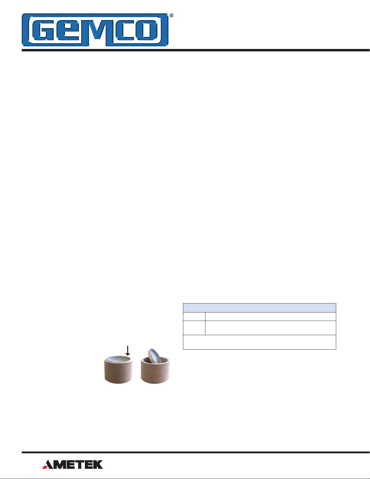
Most probes are shipped
in a Tube. To remove the
metal end cap, use a large,
at blade screw driver or a
metal rod and tap on the
inner edge of the cap until
it pivots. Grab the cap and
pull it out. Use caution as the edge of the metal cap may
be sharp.
Chapter 1: 957SSI Overview
The 957SSI Brik™ is a magnetostrictive Linear Displacement Transducer (LDT) for highly accurate continuous
machine positioning in a variety of industrial applications.
The 957SSI Brik™ provides a Serial Synchronous Interface output signal that is proportional to the position of the
magnet assembly along the length of the probe.
This sensor is built to withstand the most severe environmental conditions and is completely absolute. This means
that power loss will not cause the unit to lose position information or require re-zeroing. The non-contact design allows this device to be used in highly repetitive applications
without mechanical wear.
Features
The 957SSI has auto-tuning capability. This is the ability to
sense a magnet other than the standard slide magnet and
adjust its signal strength accordingly.
There is an indicator LED that is located at the connector
end of the probe and provides visual status information regarding the operation of the probe. Green indicates proper
or normal operation. Red indicates the loss of the magnetic signal or a probe failure. When the probe is in the
normal mode of operation, the LED will remain illuminated
green continuously.
LED Colors*
Green Magnet is present and within the active range.
Red Fault, the LDT has lost its signal from the magnet or the
magnet has moved into the Null Zone or Dead Band.
*Refer to diagnostics on page 16 for a complete list of LED colors
and functions.
NOTE: The series number on your LDT is a record of all
the specic characteristics that make up your unit. This
includes what interface type it has, its output signal and
range, the type of connector the unit uses, and stroke
length. For a translation of the model number, see Section 3.5 Part Numbering System.
If you have an RMA warranty claim, pack the probe in a
shipping tube or with stiff reinforcement to prevent the
probe from being bent in transit.
2
®
1080 N. Crooks Road • Clawson, MI 48017 • 800.635.0289 • Phone 248.435.0700 • Fax 248.435.8120 • www.ametekapt.com
Page 3
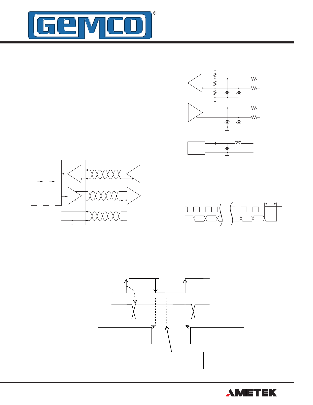
SSI (Serial Synchronous Interface)
CLOCK
DATA
SAMPLING AT
SAMPLING AT
RISING EDGE
SAMPLING
BETWEEN EDGES
SSI Sensor Input
The displacement value (position) is encoded into a 24, 25
or 26 Bit format and transmitted at high speeds. Synchronization in a closed loop system is made easy. A clock pulse
train from a controller is used to shift out sensor data: one
bit of position data is transmitted to the controller for one
clock pulse received by the sensor. The absolute position
data is continually updated by the sensor and converted
by the shift register into serial information.
SSI Logic Diagram
SSI Clock (+)
SSI Clock (-)
Position Measurement
Output Data Format Conversion
Input
Power
Supply
SSI Shift Register and Controller
SSI Data (+)
SSI Data (-)
+7 to 30 V
0V
+5V
RS-422
RS-422
Input
Power
Supply
4.7KΩ
470Ω
4.7KΩ
SSI Timing Diagram
Clock (+)
Data (+)
12V 12V
12V 12V
33V
Ferrite
Filter
10Ω
SSI Clock (+)
10Ω
SSI Clock (-)
10Ω
SSI Data (+)
10Ω
SSI Data (-)
Power Supply (+)
Common
Clock Interval
LSBMSB
Min. 16 µs
Note: Based on Gemco cable P/N 01533149 (Turck P/N RF50610-30M).
New data is placed on the "data" signal 605nS after the rising edge of the "clock" signal. This time, plus the data caused
by cable length, must be considered when determining the setup times (frequency) of the controller.
1080 N. Crooks Road • Clawson, MI 48017 • 800.635.0289 • Phone 248.435.0700 • Fax 248.435.8120 • www.ametekapt.com
®
3
Page 4

957SSI Brik™ with Magnet Sensor
Figure 1-1 957SSI Dimension Drawing for Reference
Figure 2-1 Mounting Bracket (SD0522000)
4
®
1080 N. Crooks Road • Clawson, MI 48017 • 800.635.0289 • Phone 248.435.0700 • Fax 248.435.8120 • www.ametekapt.com
Page 5

Chapter 2: Installing the LDT
Units can be ordered in span lengths up to 180 inches
long in .1 inch increments. The optional slide magnet is designed to move effortlessly along the transducer in guide
tracks, or the standard oating magnet assembly can be
positioned up to 1/4” above the unit. A variety of hardware
is available for attaching the magnet slide to the moving
portion of the process.
The 957 Brik™ has a few truly unique features. One feature is the LDT’s auto-tuning capability, the ability to sense
a magnet other than the standard slide magnet and adjust
its signal strength accordingly.
Mounting
The transducer can be mounted vertically or horizontally
using the supplied SD0522000 mounting brackets. The
mounting brackets slide in the grooves on the lower part
of the extrusion and clamp down when tightened. It is recommended to use one mounting bracket on each end and
every three feet between.
Ferro-magnetic material, which is material readily magnetized, should be placed no closer than .25” from the sensing surface of the LDT.
Magnet Assembly
Magnet choices are the Floating Magnet or the Slide Magnet assemblies. When using the Floating Magnet assembly SD0551500, the magnet should be installed within ¼”
of the sensing surface. The magnet assembly should also
be installed in such a manner that it remains an even distance from the aluminum extrusion throughout the entire
stroke. Improperly installed magnets can result in output
signal non-linearity, or loss of Magnet signal.
1080 N. Crooks Road • Clawson, MI 48017 • 800.635.0289 • Phone 248.435.0700 • Fax 248.435.8120 • www.ametekapt.com
®
5
Page 6

2.2 Magnet Position
The sliding magnet is designed to move along the extrusion.
The magnet can be slide mounted (Part # SD0521801) or
top mounted (Part # SD0521800). Refer to gure 2-2.
Figure 2-2 Magnet Sensor
6
®
1080 N. Crooks Road • Clawson, MI 48017 • 800.635.0289 • Phone 248.435.0700 • Fax 248.435.8120 • www.ametekapt.com
Page 7

Chapter 3: Wiring
!
3.1 Wiring Connections
Once the LDT has been installed, wiring connections can
be made. There are two groups of connections you will
need to make. They are as follows:
• Power Supply Connections (including ground and
shield)
• LDT Input/Output Connections
Power Supply/Ground Connections
The 957SSI is available with many different connector/wiring options. Refer to part numbering on unit in question
for proper wiring. See Section 3.5 for part numbering and
gures 3.3 - 3.8 for wiring details.
The 957SSI standard cable is a 6 Pin, 12mm, cordset.
It has 6 conductors of 24ga, with an aluminum/polyester/aluminum foil with drain wire plus an overall braid of tinned copper shield. Cable O.D. is .23
(5.7mm ). To reduce electrical noise, the shield must be
properly used. Connect the cable’s shield to the controller
system GND.
In order for the 957SSI to operate properly, the LDT’s external power supply must provide a voltage between +7
to +30 VDC. The power supply must be rated at 150mA
minimum. The power supply should provide less than 1%
ripple and 10% regulations. (The power supply should be
dedicated to the LDT to prevent noise from external loads
from affecting the position readings.)
Cable lengths
AMETEK recommends that the maximum cable length be
10 meters. Cables greater than 33 feet are available; however, proper care must be taken during installation.
Any extension to the existing cabling should be mounted in a junction box free of any other cabling, the cable
should be a twisted shielded pair with a braided shield.
The shield should pass straight thru this enclosure and not
tied to ground. When grounding the LDT, a single earth
ground should be connected to the power supply common.
The LDT power supply common should be connected to
the power supply common (-) terminal. The LDT’s shield
should be tied to the earth ground at the power supply.
Cable length limitations are based on SSI clock frequencies. Apply good industry practices for long cable
runs - keep cable away from high power AC lines and all
motor drive cables.
Always observe proper grounding techniques such as single point grounding and isolating high voltage (i.e. 120/240
VAC) from low voltage (7-30 VDC cables). Whenever possible, this cable should be run in conduit by itself. The
power supply common, the cable shield and a good earth
ground should be connected together at the location of
the power supply common. See gure 3-1 Power Supply
Wiring.
WARNING Do not route the Brik™
output cable near high voltage
sources.
UNIPOLAR
Single ended
power supply
+7 to +30 VDC
+ COM
Power+ Common
Figure 3-1 Power Supply Wiring
Controller Data Sampling
Cable Length
6 ft 1.83 m 750 kHz 1500 kHz
30 ft 9.14 m 650 kHz 1300 kHz
100 ft 30.48 m 500 kHz 1000 kHz
150 ft 45.72 m 400 kHz 800 kHz
300 ft 91.44 m 270 kHz 540 kHz
600 ft 182.88 m 160 kHz 320 kHz
1200 ft 365.76 m 90 kHz 180 kHz
Falling
Edge
Rising Edge
Cable Connectors
The 975SSI is available with various cable connection options. See gure 3-2 for standard options. Should a different connector be required for an application, please contact the factory at 800-635-0289.
Note: Minimum SSI clock frequency rate is 70 kHz.
1080 N. Crooks Road • Clawson, MI 48017 • 800.635.0289 • Phone 248.435.0700 • Fax 248.435.8120 • www.ametekapt.com
®
7
Page 8

Figure 3-2 Standard Cable Connector Options 957SSI
8
®
1080 N. Crooks Road • Clawson, MI 48017 • 800.635.0289 • Phone 248.435.0700 • Fax 248.435.8120 • www.ametekapt.com
Page 9

Startup
1. Verify connections
The 957SSI is reverse polarity protected; however, components can be damaged from improper connections or
over voltage. Before applying power verify connections
are correct.
2. Turning on power
Note that the system may execute uncontrolled movement
when power is rst applied when the 957SSI is part of a
closed loop system whose parameters have not yet been
congured.
Position Update
The position of the magnet on the extrusion is precisely
determined by a time of ight method. The 957SSI converts this position value to a 24, 25, or 26 bit Binary or
Gray code data stream where it is transmitted to the host
controller via SSI. All displacement outputs are absolute
and do not lose their position after loss of power.
Position update frequencies are available up to 6500
measurements per second (Length dependant) in Asynchronous mode, and are controller dependant in the Synchronous mode. However, if the controller interrogates
the 957LDT quicker than the LDT can provide data, the
957SSI Brik™ LDT will automatically switch to the Asynchronous mode and supply the host controller with the
most up to date positional information.
NOTE: The data in this mode will always be one update
cycle old.
Asynchronous Update Mode
The 957SSI Brik™ LDT takes measurements at its preset
internal interrogation rate (length dependant) and provides
information when requested from the host controller.
NOTE: If the controller or interface module does not specify Synchronous mode, we recommend using the LDT in
the Asynchronous mode.
Direction
The 957 can be congured increasing, decreasing, position, or velocity. Option “F” (Measure Direction Forward)
will increase counts as the magnet moves from the head
of the LDT to the tip. Option “R” will be exactly opposite.
The zero position will be located at the end of the blue
housing. This is an area where it is physically impossible
to detect a magnetic signal. If the 957SSI is in the “Measure Direction Reverse” option, the zero point will be at the
far tip of the LDT, again a position that the magnet cannot
be detected. If the velocity option is selected, the unit will
output velocity and not displacement.
Synchronous Update Mode
A clock pulse train from the host controller is used to shift
out sensor data, one bit of positional data is transmitted
to the controller for each clock pulse received by the sen-
sor. The rst clock pulse edge from the host controller
signals the LDT to make a measurement. The positional
data from this measurement will be used during the next
controller update cycle.
SSI Clock
Controller
Update
Synchronous
Asynchronous
1080 N. Crooks Road • Clawson, MI 48017 • 800.635.0289 • Phone 248.435.0700 • Fax 248.435.8120 • www.ametekapt.com
Update
Position
Internal
Repitition
Update
Position
Update
Position
Update
Position
Update
Position
Update
Position
Update
Position
Resolution
The resolution of the positional output is selectable in the
part number and can be ordered in English (Imperial) or
metric units. Selections 1 thru B are valid options. Refer
to section 3.5 Part Numbering for further details.
®
9
Page 10

Figure 3-3: Wiring for Connector
Option "S", 6 Pin 12 mm
10
®
1080 N. Crooks Road • Clawson, MI 48017 • 800.635.0289 • Phone 248.435.0700 • Fax 248.435.8120 • www.ametekapt.com
Page 11

Figure 3-4: Wiring for Connector
Option "C", Integral Cable Assembly
1080 N. Crooks Road • Clawson, MI 48017 • 800.635.0289 • Phone 248.435.0700 • Fax 248.435.8120 • www.ametekapt.com
®
11
Page 12

Figure 3.5 Wiring Diagram
Option "H", High Temperature Integral
Cable Assembly
12
®
1080 N. Crooks Road • Clawson, MI 48017 • 800.635.0289 • Phone 248.435.0700 • Fax 248.435.8120 • www.ametekapt.com
Page 13

Figure 3-6:
Wiring for Connector
Option "E", 10 pin MS connector
1080 N. Crooks Road • Clawson, MI 48017 • 800.635.0289 • Phone 248.435.0700 • Fax 248.435.8120 • www.ametekapt.com
®
13
Page 14

Figure 3-7:
Option "M", 7 Pin DIN
Wiring for Connector
14
®
1080 N. Crooks Road • Clawson, MI 48017 • 800.635.0289 • Phone 248.435.0700 • Fax 248.435.8120 • www.ametekapt.com
Page 15

Figure 3-8: Wiring for Connector
Option "B", 8 Pin DIN
1080 N. Crooks Road • Clawson, MI 48017 • 800.635.0289 • Phone 248.435.0700 • Fax 248.435.8120 • www.ametekapt.com
®
15
Page 16

3.2 Features
3.3 Troubleshooting for 957SSI
Automatic Gain Control
The Automatic Gain Control feature will automatically
search and nd the magnet on power up. If power is applied without a magnet on the LDT, the LED will turn RED
indicating no magnet signal is detected. Turn power off
and place magnet within the active stroke area. Re-apply
power.
Accessories
P/N Description
949029L6 6 Foot, 6 Pin, Straight, 12mm Cable
949030L6 6 Foot, 6 Pin, Right Angle, 12mm Cable
SD0554600L6 6 foot, 8 Pin, Straight Cable, for Option B
SD0558500L6 6 Foot, 7 Pin, Straight Cable for Option M
SD0521800 Slide Magnet, Top Swivel
SD0521801 Slide Magnet, Top Swivel
SD0551500 Large Floating Magnet
SD0522000 Mounting Foot
Consult factory for complete accessory offerings.
Diagnostics
The 957SSI is equipped with a tri-color LED next to the connector to help while troubleshooting. The chart below explains the possible LED colors and the faults they represent.
If there is ever a loss of magnet, the LED will turn red and
the unit will transmit a position of zero.
Troubleshooting describes common problems that may
occur when installing the LDT and offers possible solutions to these problems. If, after reading this appendix,
you are unable to resolve a problem, contact our technical support department at 800-635-0289.
General Checks
Make sure that the magnet is located within the LDT’s active stroke area. Magnet assemblies should be positioned
so that they can move freely over the entire area of the
active stroke without binding.
NOTE: Ferromagnetic material (material readily mag-
netized) should be located no closer than 0.25” from the
sensing surface of the LDT. This includes mounting brackets, magnet spacers, magnet brackets, and mounting
screws. Ferromagnetic material can distort the magnetic
eld, causing adverse operation or failure of the LDT.
Check all LDT wires for continuity and/or shorts. It is preferable that the cable between the LDT and the interface
device be one continuous run. If you are using a junction
box, it is highly recommended that the splice junction box
be free of AC and/or DC transient-producing lines. The
shield should be carried through the splice and terminated
at the interface device end.
Power Supply Check
957 LED Output Summary
Output 957SSI
Flashing Red Flash memory corrupt
Flashing Red/Green EE memory corrupt
Flashing Yellow Communication/programming mode
Fast Flashing Yellow Clock input held asserted at power up
Solid Red No magnet signal detected
Green/Red Blip
(1s to 0.12s)
Solid Green Normal probe operation; magnet signal
Solid Yellow No SSI clock pulses detected
Yellow/Red Blip
(1s to 0.12s)
Green/Yellow Blip
(1s to 0.12s)
Max Gain but signal detected and within range
and SSI clock operational
SSI clock pulses do not match
LDT SSI data length
LDT data not Synchronous with controller
(if LDT is programmed for Synchronous mode)
Alarm Bit
The 957SSI can be congured to output a fault bit
should there be a problem with the LDT.
16
®
1080 N. Crooks Road • Clawson, MI 48017 • 800.635.0289 • Phone 248.435.0700 • Fax 248.435.8120 • www.ametekapt.com
This will help you to determine if your power supply is
adequate for the LDT to operate properly, or if the LDT’s
cable has a short or open.
In order for the 957SSI to operate properly, the external
power supply must provide a voltage level between 7 to 30
VDC. A power supply providing voltage above this speci-
ed range may damage the LDT. A power supply providing power below this specied range will not be sufcient
to power the LDT. When powering more than one Brik™
on a single power supply, remember that each Brik™ typically requires 1.3 watts of power. The amount of current
draw will vary based on the input voltage, as well as other
operating parameters. To approximate the current draw
for a particular LDT, divide the LDT wattage by the input
voltage. For example, 1.3 watt divided by 24 VDC equals
55mA.
Page 17

If your LDT is not operating properly, the LDT’s cable may
have an open or short, or the power supply is not supply-
ing sufcient power. To verify this, perform the following
steps:
1. Turn the power supply off.
2. Remove the mating connector from the LDT.
3. Turn the power supply on.
4. Using a digital voltmeter, check from the Power Supply Common to the Power Supply + on the mating
end of the cable for a level between +7 and +30
VDC.
If reading is between 7 and 30 VDC, turn power supply off
and go to step 7. If reading is below 7 VDC, either your
power supply is not providing enough power or the LDT’s
cable possibly has a short/open. Readings of no voltage
or minimal voltage (less than 5 volts) may be due to short/
5. Turn the power supply off.
6. Check the continuity of the individual wires of the
cable between the power supply and the LDT. Check
for continuity from one end of the cable to the other.
Also verify that no shorts exist between pins.
7. Reconnect the mating connector to the LDT.
8. Turn power supply on.
9. Using a digital voltmeter, check the power supply’s
“+” and “-” terminals for a voltage between 7 and 30
VDC.
Low voltage readings may indicate a power supply with a
wattage (current) rating that is too low. (Each LDT requires
approximately 1.3 watts). If the cabling checks out in step
6 and your voltage is below 7 VDC, check your power supply current rating. If voltage is between 7 to 30 VDC and
the LDT is still inoperative, contact factory.
open in the cable. If reading is NOT between 7 and 30
VDC, go to step 5. If reading is above 30 VDC, adjust power supply or replace.
* See Section 3.4: Specications for more information on
power consumption.
3.4 Specications
Specications
Connector Interface 6 Pin 12mm
Integral cable ass'y, 7 Pin or 8 Pin
DIN
Displacement 1” to 180" Vibration 30 Gs
Dead Band 2.65" (67.31 mm) standard Update Time Measuring Length 300 750 1000 2000 5000mm
Null Zone 2.00" (50.8 mm) standard Approvals CE (EMC) Non-linearity < 0.01% or +/- 0.005”, whichever
Enclosure Rating IP67, IEC 600529 Input Voltage 7 to 30 VDC Diagnostics Tri-Color LED beside connector/
Measured Variables Single Magnet Displacement, Consult
Factory for Velocity or Differential
Operation
Shock 1000 Gs
Current
Draw
IEC 60068-2-27
IEC 60068-2-6
Measurements/sec. 4.0 2.4 2.0 1.1 0.5k
1.3 watts, (53mA at 24 VDC) typical* Operating
Output Type 24, 25 or 26 Bit, Binary or Gray
Code (optional parity and error
bit), Position Updates
Resolution English or Metric Units
Metric: 1, 5, 10, 20 micron (5
micron standard)
English: .00005", .0001", .0005",
.001"
Consult Factory for Others.
Hysteresis 0.008”
is greater, (+/- 0.003" Typical)
cable exit, See 'LED Output Summary Table' on page 13
Temperature -40° to 185° F ( -40° to 85° C)
Interface Specications Input SSI Clock
Output Data Pulse
Resistance
SSI Clock Frequency Minimum 70 kHz Maximum 150 kHz
NOTE: Specications subject to change and are based on a typical 48” stroke. *1.3 watt typical at 1ms interrogation time. Faster interrogation times increase power consumption.
RS-422, 470 Ohm termination
resistance
RS-422, 2.0V min. @ 100 Ohm
termination
Storage
Temperature
Repeatability Equal to Output Resolution
-40° to 221° F
(-40° to 105° C)
Cable Specications
Cable Type Gauge Jacket Temp Bend Radius
Connector Options "S", "M", "B", "C" 24 PVC -50° to 105° C Moving Applications - 2.36"
High Temp Integral Cable "H" option 22 Teon -70° to 200° C Moving Applications - 4.6"
Connector Option "E" 22 Polyurethane -50° to 105° C Moving Applications - 2.3"
1080 N. Crooks Road • Clawson, MI 48017 • 800.635.0289 • Phone 248.435.0700 • Fax 248.435.8120 • www.ametekapt.com
Fixed applications - 1.18"
Fixed applications - 2.3"
Fixed applications - 1.2"
®
17
Page 18

3.5 Part Numbering System
Brik
Extrusion
VP957 0120 1
Units of Measure
Output Type
S SSI
Stroke Length
1" to 180". Insert stroke length to 0.1 inch. Enter as
a four-place number. Example: A 12.0” stroke enters
as 0120.
OR
Insert stroke in millimeters to 5mm. Enter as a fourplace number. Example: 305mm stroke entered as
0305M.
E Inches
M Metric
Connector Option
S Standard M12 6 Pin
Integral Cable Assembly. Insert length
C_
in feet. Example: C6 = 6 foot cable. *
M 7 Pin DIN, MTS Style D70
B 8 Pin DIN, Balluff S32
High Temp., Integral cable assembly
200° C Teon Cable. Insert length
H_
in feet.
Example: H6= 6 foot High Temp Teon
Cable.
Environmental 10 Pin MS connector
E
compatible with SD0439700 cable
assemblies
* If stroke is in inches, cable is in feet.
If Stroke is in metric, cable is in
meters.
SS
Data Length
1 24 Bits
2 25 Bits
3 26 Bits
Data Format
B Binary
G Gray
Position Update
S Synchronous
A Asynchronous
Direction
F Measures Direction Forward
R Measures Direction Reverse
V Velocity
B
S
F
1
Options
X None
A
Resolution
1 .005mm
2 .01mm
3 .05mm
4 .1mm
5 .02mm
6 .002mm
7 .001mm
8 .00005"
9 .0001"
A .0005"
B .001"
NOTE: Contact our Technical Support at 1-800-635-0289 for custom congurations.
XE
Alarm Bit 25,
Parity 26
18
®
1080 N. Crooks Road • Clawson, MI 48017 • 800.635.0289 • Phone 248.435.0700 • Fax 248.435.8120 • www.ametekapt.com
Page 19

Part Number
Serial Number
Purchase Order Number
Sales Order Number
Comments
NOTES:
Page 20

Other Products
®
MADE IN AMERICA
Copyright 2013 by AMETEK AUTOMATION & PROCESS TECHNOLOGIES. All Rights Reserved. Made in the USA.
1080 North Crooks Road, Clawson, MI 48017
Phone: 248-435-0700 Toll Free: 800-635-0289
Email: apt.orders@ametek.com Web: www.ametekapt.com
957.M0R
10/13.Z400
 Loading...