

Page 1

AM8a PCM/VF Call Analyzer
Test Procedure Guide
Addendum to
AM8a Instruction Manual
Page 2

AM8A PCM/VF CALL ANALYZER
Test Procedure Guide
Addendum to
Am8a Instruction Manual
June 1996
Technical Data Subject to
Change without Notice
760 Arrow Grand Circle
Covina, CA 91722 USA
TEL 626.915.5441
FAX 626.915.7181
www.ameritec.com
For extra copies of
this manual order
P/N 18-0133 © 2000 Ameritec Corporation
Page 3

AM8a Test Procedure Guide (18-0133) Addendum to 18-0037
AM8a PCM/VF Call Analyzer
Test Procedure Guide
Addendum to
AM8a Instruction Manual
June 1996
INTRODUCTION
This Test Procedure Guide provides summarized information about the setup and
operation of the AM8a PCM/VF Call Analyzer. It consists of General Information on
the operation of the unit and Application Notes.
This Test Procedure Guide can be ordered separately as Part Number 18-0133. It is
also included at the end of AM8a PCM/VF Call Analyzer Instruction Manuals (18-
0037). A quick reference card is also available separately by contacting Ameritec
Sales Department.
TABLE OF CONTENTS
GENERAL INFORMATION.........................................................................................1
THE FRONT PANEL....................................................................................................1
START-UP AND DEFAULT SETTINGS........................................................................2
SHIFT KEY..................................................................................................................2
THE SETUP SECTION .................................................................................................2
SETUP: CONFIGURATION .....................................................................................2
SETUP: EMULATE ...................................................................................................3
SETUP: ANALYZE...................................................................................................3
SETUP: AUTODIAL.................................................................................................3
THE DISPLAY SECTION.............................................................................................3
June 28, 1996 i
Page 4

AM8a Test Procedure Guide (18-0133) Addendum to 18-0037
THE ON/OFF SECTION..............................................................................................3
INPUT......................................................................................................................3
TIMS ........................................................................................................................3
TALK .......................................................................................................................3
AUTO.......................................................................................................................3
FUNCTION KEYS AND STATUS LEDs .......................................................................4
SEIZE.......................................................................................................................4
START......................................................................................................................4
RING........................................................................................................................4
REV (Reverse) ..........................................................................................................4
STORE/RECALL OF AM8a PARAMETERS...................................................................4
APPLICATION NOTE #1: CUSTOM CALLING FEATURES
USING THE AUDODIAL FIELD..................................................................................5
APPLICATION NOTE #2: DS1/T1 DROP AND INSERT...............................................8
SETUP PROCEDURES ..............................................................................................8
CONFIGURE DIALED DIGITS AND DIAL TYPE ......................................................10
DROP AND INSERT TEST........................................................................................11
APPLICATION NOTE #3: DIRECT INWARD DIAL (DID)/911 ....................................12
SETUP PROCEDURES ..............................................................................................12
OPERATION............................................................................................................13
APPLICATION NOTE #4: SLC®96 MONITORING
AND DATA LINK ANALYSIS ....................................................................................14
SETUP PROCEDURES ..............................................................................................14
VIEW SPAN RESULTS AND ALARM CONDITIONS...............................................15
VIEW SIGNALING EVENTS (DIGITS, TONES, SEIZURES) .....................................16
MODE II OPERATION..............................................................................................16
DATALINK MONITORING .....................................................................................16
June 28, 1996 i i
Page 5

AM8a Test Procedure Guide (18-0133) Addendum to 18-0037
APPLICATION NOTE #5: DS1/T1 SIGNAL MONITORING .........................................18
SETUP PROCEDURES ..............................................................................................18
PARAMETER CHANGES..........................................................................................19
METER DISPLAY (A/B BIT STATES, SPAN ERRORS, ETC.) .....................................19
A/B SIGNALING .....................................................................................................20
APPLICATION NOTE #6: ORIGINATING
OR TERMINATING A DS/T1 CALL .............................................................................21
SETUP PROCEDURES ..............................................................................................21
OPERATION............................................................................................................22
TERMINATING AN INBOUND CALL .....................................................................23
ORIGINATING A CALL ...........................................................................................23
APPLICATION NOTE #7: DIGIT ANALYSIS
AND EXCEPTION REPORTING..................................................................................24
SETUP PROCEDURES ..............................................................................................24
CONFIGURING ANALYZE THRESHOLDS .............................................................25
OPERATION............................................................................................................26
DISPLAYING EXCEPTIONS......................................................................................26
June 28, 1996 i i i
Page 6

AM8a Test Procedure Guide (18-0133) Addendum to 18-0037
AM8a PCM/VF Call Analyzer
Test Procedure Guide
GENERAL INFORMATION
This section provides general information about the front panel of the Ameritec
AM8a Test Set. Topics are limited to the location and function of switches, keys,
LEDs, and displays used for controlling the unit and indicating its operational
status. Refer to the AM8a Instruction Manual for a complete description of each
front panel component if required.
THE FRONT PANEL
The front panel consists of four (4) major areas:
1. The Setup section.
2. The Display section.
3. The On/Off section.
4. The Function keys and Status LEDs.
A
meritec
PCM/VF CALL ANALYZER
> i K N L O M H X 9 x 9 4 9 9 9 0 8 T t y h
i 00:00:00 COT Trunk Assign TS=09 CH=05
DISPLAY
EVENTS METER
CONFIG'N EMULATE ANALYZE AUTO DIAL
1 2 34 56
WAIT DT WAIT WINK WAIT FLASH UNBAL TOGGLE BLANK
ON / OFF
INPUT TIMS TALK
#
*
KP
ST
+ / -
AUTO
VALUE
SETUP
DIAL
FREEZE PRINT CANCEL
BCD
A
FIELD
7
8
MENU
June 28, 1996 1
STORE RECALL
9
0
SHIFT
PCM2 PCM2
CAUTION: 10 VOLTS MAX
SEIZE
START
TX/2W
!
TRUNK INPUTS
SEND TONE
RING
REV
RXTX/2W RX
E & M
Model AM8a
TRUNK /SLC
TERMINAL/LINE
TYPE
EMULATE
/
OFFHOOK
E & M / SLC
LOOP / DID
R -GND
GND ST / SF
PCM1
a b c d
T/R
LOOP
PCM2
E/M SB/SG TX/2W RX
E
SWITCH
EMULATE
T-GND
RINGING
T+R–
T–R+
a b c d
TIMS
POWER
VOLUME
M
TALK
HANDSET
Page 7

AM8a Test Procedure Guide (18-0133) Addendum to 18-0037
In addition to these four areas, the panel contains the following keys, switches and
jacks:
* The Store and Recall keys used to store and then recall and execute
either front panel setups or auto-dial sequences.
* A volume control knob (to the right of the display) to control the volume
of the speaker located in the bottom of the unit.
* The Power ON/OFF button (above the volume control knob).
* Bantam jacks (bottom right hand corner) for connecting the test set to the
line.
* A SHIFT key (left of bantam jacks) that controls access to green function
keys or red dialing keys. Press SHIFT key once to access green keys and
twice to access red keys.
START-UP AND DEFAULT SETTINGS
When the AM8a is initially powered on, it runs through a self-test procedure. All
LEDs light for approximately three (3) seconds. After 3 seconds, if no internal
problem is diagnosed, the unit assumes its default state, which is to monitor a
DS1/T1 circuit (channel 1). If the user desires to monitor a DS1 circuit, he need only
to connect the circuit to the test set and set the INPUT selection switch to ON.
SHIFT KEY
The SHIFT key is located to the left of the bantam input jacks of the AM8a. This
key allows the AM8a to use one key for several different functions. When the
SHIFT key is not illuminated (off), the function of the keys will be written in
black/white. With the SHIFT key pressed once, the green LED will illuminate and
now any key that has green functions written above it can now be accessed.
For example, to select the EMULATE menu, the user would press [SHIFT], [6]. To
access any of the red dial functions, the user should press the SHIFT key twice and
then the key directly above the red function. Once a key has been pressed after the
SHIFT key is illuminated, the SHIFT LED will turn off and the user will need to
repeat the process to access another green or red function.
June 28, 1996 2
Page 8

AM8a Test Procedure Guide (18-0133) Addendum to 18-0037
THE SETUP SECTION
The SETUP section is divided into four (4) different areas: CONFIGURATION,
EMULATE, ANALYZE and AUTODIAL. These areas represent menus that control
various setup aspects for configuring the AM8a for a given test. Each area is briefly
described below:
SETUP: CONFIGURATION
This menu determines whether the AM8a will be used for analog or T1 circuits and
what type of circuit will be monitored or emulated. Additionally, RS232 port
selections, types of events that the user wishes to display and which end of the
circuit the AM8a is emulating are all selected here.
SETUP: EMULATE
This menu is primarily used to configure the C.O. characteristics of a circuit such as
ring voltage, dial tone characteristics and cadences, loop length and start signal.
Additionally, if the user desires to offset any dialed numbers, the ability to control
digit levels, frequencies and on/off timing can be set here for pulse or tone dialing.
SETUP: ANALYZE
This menu is only used to set up user-defined error thresholds for any signaling event
whether it be wink timing, digit analysis, tone analysis, etc. This menu does not
affect the AM8a’s ability to decode any event — only whether that event is to be
considered in violation of preset thresholds.
SETUP: AUTODIAL
This menu allows the user to program up to 10 autodial sequences. These dialed
number strings may be up to 60 events each and can contain complex variables such as
wait for wink, pause for tone, toggle from MF to DTMF, etc. The autodial sequence
selected is enabled by toggling the AUTO LED to the ON position in the bottom left
corner of the unit.
June 28, 1996 3
Page 9

AM8a Test Procedure Guide (18-0133) Addendum to 18-0037
THE DISPLAY SECTION
The DISPLAY section is divided into EVENTS and METER. The EVENTS display is
selected when the user desires to capture digits and signaling events. The METER
display is used to Display VOM measurements, display PCM measurements or look
at SLC®96 alarm fields.
THE ON/OFF SECTION
This section allows the user to selectively toggle ON/OFF the following functions:
* INPUT - This switch electronically connects the test set to the line under
test.
* TIMS - This switch activates the TIMS jacks on the AM8a.
* TALK - This switch activates the internal microphone.
* AUTO - This switch acts to activate the autodial sequence if emulating
a terminal device or provide the proper start signal upon detection of
seizure if emulating a switch.
FUNCTION KEYS AND STATUS LEDs
In the center of the AM8a front panel, there reside 4 function keys labeled SEIZE,
START, RING (SEND TONE) and REV. These keys provide manual control (on/off)
of these functions and are described briefly below:
* SEIZE - Controls On Hook and Off Hook state of circuit under test.
* START - This key will provide the start signal as defined in the
SETUP: EMULATE section.
* RING - This keys initiates the ring generator. The ring generator will
continue to produce ringing as defined in SETUP: EMULATE section until
ring trip is detected.
June 28, 1996 4
Page 10

AM8a Test Procedure Guide (18-0133) Addendum to 18-0037
* REV - (Reverse) This key will provide reverse battery to the circuit
under test.
The status LED's located in the front panel blue box give the user an immediate
indication of how the unit has been configured for a given test. On hook/Off hook
status, ringing, battery reversal, etc. are also displayed to allow the user to pinpoint
any potential network problem.
STORE/RECALL OF AM8a PARAMETERS
The STORE and RECALL keys are located in green over the “9” and “0” keys. To
access these functions, the user must remember to first press the SHIFT key before
pressing the STORE or RECALL key.
The AM8a provides up to 20 locations for storing SETUP: CONFIGURATION
parameters. These locations are numbered 00 through 19. Additionally, 20 more
locations are provided for storing SETUP: EMULATE/ANALYZE parameters and
they are numbered 20 through 39.
It is important to remember that because the SETUP: CONFIGURATION
parameters are stored separately from the SETUP: EMULATE / ANALYZE
parameters, the user needs to store each set of parameters for a given test. To STORE
the SETUP: CONFIGURATION parameters, the AM8a must first have its SETUP:
CONFIGURATION LED on. Likewise, to STORE any parameters in the SETUP:
EMULATE / ANALYZE section, one of those two LEDs must be on.
APPLICATION NOTE #1
Custom Calling Features
Using the Autodial Field
The following example illustrates how the AM8a can be configured to simulate a
conference call over the Sprint network by programming a complex dial sequence into
the AM8a’s autodial field. Through the front panel keypad an operator can dial
any sequence of digits and events either manually or automatically and store up to 10
of these sequences in the autodial section for later recall.
June 28, 1996 5
Page 11

AM8a Test Procedure Guide (18-0133) Addendum to 18-0037
This example shows the sequence of events used to test the conference calling feature
on a switch utilizing the Sprint network:
1. Power up the AM8a and wait 3 seconds for self test to complete.
2. Press [SHIFT], [8] to enter autodial section.
3. With the blinking cursor to the far left of the display, select the
appropriate autodial field (0 - 9) by pressing the MENU up/down
keys until the desired field is displayed.
4. With the field selected, enter in the dialed number, in this case:
*nnzzzzzzzzzz#*8008778000#TT08189155441-bbbbbbbbbbbbbb-kkk
where,
*nnzzzzzzzzzz# is a MF digit string, whereby nn = facilities code and
identifies that the call is coming from a pay phone, hotel, prison,
etc. and zzzzzzzzzz = the ANI string that identifies the switch
the call is originating from,
*8008778000# is a MF digit string that routes the call to a Sprint
switch in Kansas City,
TT is the AM8a command to toggle back to DTMF dialing.
08189155441 is the desired party’s number that has been dialed in
DTMF
- is the AM8a command that provides a 3 second wait before
dialing next digit
bbbbbbbbbbbbbbb is the phonecard PIN number
- is the AM8a command that provides a 3 second wait before dialing
next digit.
kkk is a 3 digit DTMF Authorization Code that is used when a
number of users share the same PIN number.
June 28, 1996 6
Page 12

AM8a Test Procedure Guide (18-0133) Addendum to 18-0037
Note that the events TT and - require the user to first press the [SHIFT] key twice in
order to be entered into the sequence of events.
5. Press [SHIFT], [5] to setup the AM8a for terminal dialing.
6. Press the MENU keys until the display shows:
IMITATE MODE
switch monitor
7. Press the FIELD and VALUE keys until the display shows:
IMITATE MODE
te/line emulate
8. Press [SHIFT], [6] to setup the AM8a for MF dialing.
9. Press the MENU keys until the display shows:
LOOP TYPE START SIGNAL
pulse wink
10. Press the FIELD and VALUE keys until the display shows:
LOOP TYPE START SIGNAL
mf wink
11. If it is desirable to change any other values, such as changing from
E&M to loop start, repeat the same process as shown in steps 5 - 10.
The AM8a will always power up in the same configuration, so it is
only necessary to change those values that are different from its
default state.
12. The AM8a is now ready to originate a call. Press [SHIFT], [1] so that
the AM8a will display the call.
13. Press [SHIFT], [KP] to toggle the INPUT LED on. This connects the
AM8a to the circuit under test.
June 28, 1996 7
Page 13

AM8a Test Procedure Guide (18-0133) Addendum to 18-0037
14. Press [SHIFT], [AUTO] to toggle the AUTODIAL LED on. The AM8a
will now dial upon the detection of the proper start signal, in this
case, a wink. Make sure the autodial number you programmed
earlier is still displayed in the SETUP: AUTODIAL section if the
AM8a does not outpulse.
15. Press the SEIZE key to initiate an Off Hook.
16. By turning up the volume knob, the user should hear the call take
place.
17. The user can now conference on another party by manually dialing
the following digits from the front keypad:
a. Press * for approximately 3 seconds
b. Press 12 and wait for a progress tone
c. Press 0 + the desired telephone number of the party you wish to
conference
d. After answer, press * for approximately 3 seconds
e. Press 13 to bridge all three parties together
f. Press SEIZE to hang up
APPLICATION NOTE #2
DS1/T1 Drop and Insert
This application note describes the method of “dropping” a DS0 signal out of a DS1
stream and “inserting” a new DS0 signal into the same timeslot in the DS1 stream.
This is all performed without interrupting service on the remaining 23 timeslots.
Drop and Insert can be performed in either direction (east/west, line/equip.), but
only in one direction at a time. The direction not selected will be idled.
June 28, 1996 8
Page 14
AM8a Test Procedure Guide (18-0133) Addendum to 18-0037
SETUP PROCEDURES
1. Power up the AM8a and wait 3 seconds for self test to complete.
2. Press [SHIFT], [5] to enter the SETUP: CONFIGURATION menu.
3. Press the MENU keys until the display shows:
INPUT
pcm 1 on
4. Press the FIELD and VALUE keys until the display shows:
INPUT
rpt1 to 2
or
INPUT
rpt2 to 1
5. Press [SHIFT], [KP] to toggle the INPUT LED on. This connects the
AM8a to the PCM1 and PCM2 jacks.
6. Press [SHIFT], [2] to enable the meter display.
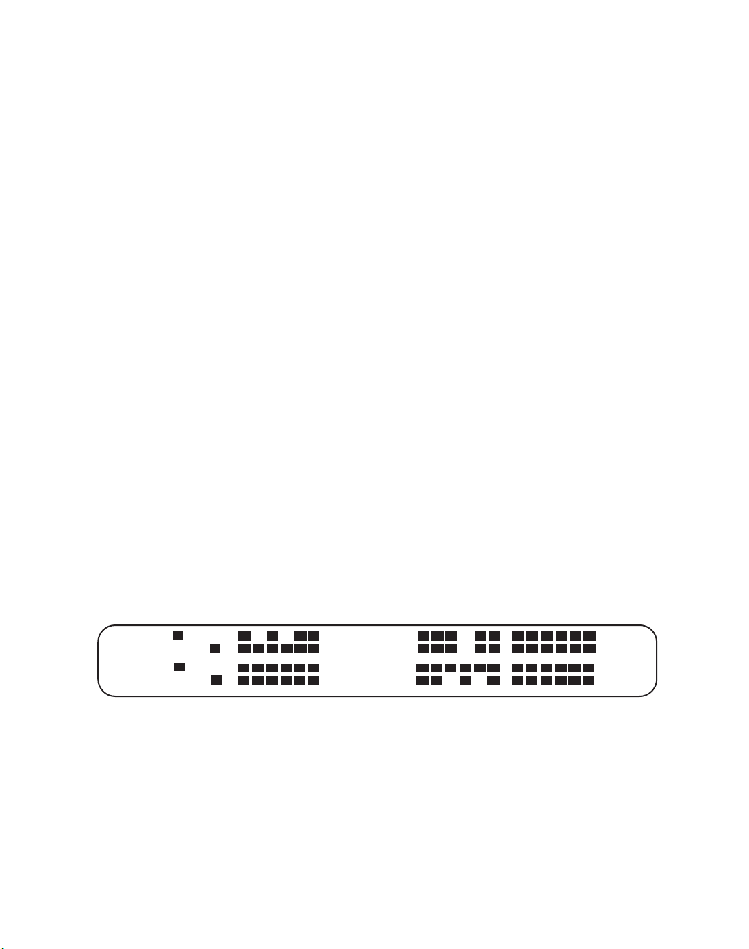
7. Press the MENU up/down keys until the display shows the bit
states of all 24 channels.
TX A B
RX A B
June 28, 1996 9
• • • • • •
• • • • • •
Page 15

AM8a Test Procedure Guide (18-0133) Addendum to 18-0037
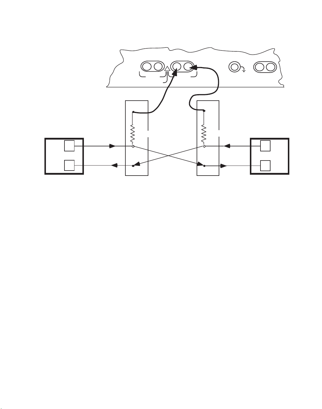
8. Connect the AM8a PCM jacks to the DSX as follows:
a. Connect the RX for PCM1 to the monitor jack of the direction
that should source timing,
IMPORTANT NOTE: The AM8a is expecting a “padded” signal into the
PCM1 and PCM2 X jacks consistent with that of a
signal from a resistor isolated monitor jack. If the
monitor jacks are not resistor-isolated, use the
Ameritec resistor cables provided with the AM8a
(P/N 48-0131).
b. Locate the monitor jack for the other direction (LED above DSX
MON JACK will be blinking) and connect the RX for PCM2 to it.
c. At this point, ABCD signaling bit LEDs on AM8a front panel
should stop scrolling indicating frame synchronization has been
established. If these LEDs are still scrolling, the user should
check to see that either the correct framing format has been
chosen, the cables used are good or that the timing source is
connected to the PCM1 RX input jack.
d. Next, connect the PCM1 TX jack to the DSX IN (lower) jack
associated with the monitor jack that is connected to PCM1 RX.
e. Finally connect PCM2 TX jack to the DSX IN (lower) jack
associated with the monitor jack that is connected to PCM2 RX.
June 28, 1996 10
Page 16
AM8a Test Procedure Guide (18-0133) Addendum to 18-0037
n
n
Network Equipment
9. Using the A/B bit display, identify either an idle timeslot or the
timeslot you are interested in dropping out.
10. To select a channel other than channel 1 to drop and insert, Press
[SHIFT], [5].
TXRXTX RX
!
PCM2
CAUTION: 10 VOLTS MAX
MON
860 Ω
IN IN
PCM1
TX/2W RXA/B
LOOP TIMSTRUNK INPUTS
MON
860 Ω
n
n
Network Equipment
11. Press the MENU keys until the display shows:
12. Press the FIELD keys until the “1” is blinking and then enter the
correct channel number to drop and insert. Verify through the
speaker that the channel is still idle.
13. Press the MENU keys until the display shows:
June 28, 1996 11
CHAN
1
MODE
monitor
Page 17

AM8a Test Procedure Guide (18-0133) Addendum to 18-0037
14. Press the FIELD and VALUE keys until the display shows:
MODE
emulate
The AM8a is now working in a drop and insert mode of operation for an E&M circuit.
For other types of circuits, it would be necessary to select those values in the SETUP:
CONFIGURATION menu.
CONFIGURE DIALED DIGITS AND DIAL TYPE
1. Press [SHIFT], [8] to enter autodial section.
2. With the blinking cursor to the far left of the display, select the
appropriate autodial field (0 - 9) by pressing the MENU up/down
keys until the desired field is displayed.
3. With the field selected, enter in the dialed number. (If dialing in
MFR1, remember to include the KP and ST digits in this sequence).
4. To change the dial type from pulse to MFR1, press [SHIFT], [6].
5. Press the MENU keys until the display shows:
LOOP TYPE START SIGNAL
pulse wink
6. Press the FIELD and VALUE keys until the appropriate dial type
and start signalhas been selected.
7. Press [SHIFT], [AUTO] to enable the autodial capabilities of the
AM8a.
June 28, 1996 12
Page 18

AM8a Test Procedure Guide (18-0133) Addendum to 18-0037
DROP AND INSERT TEST
1. The AM8a is now ready to originate a call. Press [SHIFT], [1] so that
the AM8a will display the call.
2. To originate a call, Press the SEIZE key. The AM8a will
automatically outpulse the digit sequence selected in the
SETUP: AUTODIAL menu. If manual dialing is desirable, simply
toggle off the AUTO LED and key in the desired digits after the
appropriate start signal is returned to the AM8a.
3. Upon answer by the far end, the user may talk by enabling the
speakerphone by pressing the [SHIFT], [TALK] keys. Alternatively,
a tone could be sent by pressing [SHIFT], [RING]. The AM8a will
default to 1004 Hz tone at -10 dBm.
4. To disconnect the call, simply press the SEIZE key again.
5. To switch directions and emulate the C.O. side, press [SHIFT], [5].
6. Press the MENU keys until the display shows:
7. If you were using “rpt1 to 2” press the VALUE up key to select “rpt2
to 1” or alternatively, if you were using “rpt2 to 1” press the VALUE
down key to select “rpt1 to 2”.
8. Toggle the AUTO LED on for the AM8a to automatically provide
the appropriate start signal upon detection of seizure.
June 28, 1996 13
INPUT
rpt1 to 2
Page 19

AM8a Test Procedure Guide (18-0133) Addendum to 18-0037
APPLICATION NOTE #3
Direct Inward Dial (DID)/911
This application note will explain the procedure for emulating the customer
terminal with the AM8a. This allows for DID/911 turn-ups to occur without the
need for customer equipment to be in the picture. The user can now know if the circuit
will work before the customer is hooked up and the service is delivered, eliminating
turn up problems and allowing for quick and error free service to be delivered.
SETUP PROCEDURES
1. Power up the AM8a and wait 3 seconds for self test to complete.
2. Press [SHIFT], [5] to enter the SETUP: CONFIGURATION menu.
3. Press the MENU keys until the display shows:
IMITATE MODE
switch monitor
4. Press the FIELD and VALUE keys until the display shows:
IMITATE MODE
te/line emulate
5. Press the MENU keys until the display shows:
ANALOG IMPEDANCE ANALOG/PCM
900 ohms pcm loop clk
6. Press the FIELD and VALUE keys until the display shows:
ANALOG IMPEDANCE ANALOG/PCM
900 ohms analog
June 28, 1996 14
Page 20

AM8a Test Procedure Guide (18-0133) Addendum to 18-0037
7. Press the MENU keys until the display shows:
TRUNK TYPE
e&m 4w
8. Press the FIELD and VALUE keys until the display shows:
TRUNK TYPE
did
9. Press [SHIFT], [6] to enter the SETUP: EMULATE menu.
10. Press the MENU keys until the display shows:
LENGTH ohm
1200
11. If 1200 ohms loop length is not desirable, use value keys to adjust
from 0 to 2100 ohms.
12. Press the MENU keys until the display shows:
13. If pulse dialing is not desirable, press the value keys until DTMF is
selected.
OPERATION
1. Press [SHIFT], [1] so that the AM8a will display the call.
2. Press [SHIFT], [KP] to toggle the INPUT LED on. This connects the
AM8a to the circuit under test.
3. Press [SHIFT], [AUTO] to automatically enable the start signal upon
seizure.
June 28, 1996 15
LOOP TYPE
pulse
Page 21

AM8a Test Procedure Guide (18-0133) Addendum to 18-0037
4. Upon detection of seizure from C.O. end, the AM8a will provide a
wink and then capture the outpulsed digit sequence.
5. By pressing the FIELD keys, place the cursor under the “>” at the
far left of the digit string. If there are any errored parameters in
the display, the bottom line will flash. If flashing, the user can
then scroll across each event in the display until a flashing
parameter is noticed, indicating the event that is errored. If the
bottom display line doesn’t flash, the call occurred with no errors.
APPLICATION NOTE #4
SLC®96 Monitoring and Data Link Analysis
With loop carrier problems, it is necessary to quickly determine if the cause of
trouble lies within the remote terminal, the digital span line or the central office
terminal. The AM8a PCM/VF Call Analyzer allows both central office and field
technicians to quickly isolate problems on SLC®96, Integrated SLC® and DISC*S
systems by monitoring T1 span line errors, SLC® Datalink and Alarm information,
signaling activity and channel level impairments.
SETUP PROCEDURES
1. Power up the AM8a and wait 3 seconds for self test to complete.
2. Press [SHIFT], [5] to enter the SETUP: CONFIGURATION menu.
3. Press the MENU keys until the display shows:
4. Press the FIELD and VALUE keys until the display shows:
June 28, 1996 16
FRAMING
D3/D4
FRAMING
SLC®96 I
Page 22

AM8a Test Procedure Guide (18-0133) Addendum to 18-0037
If Mode II is desired, press the value key until “SLC®96 II” is displayed.
5. Press the MENU keys until the display shows:
SLC® TYPE
single party
Single party is selected for loop start trunks for Mode I and Mode II. If ground start is
desirable, press the value keys until “universal vg” is selected.
6. Connect the AM8a’s PCM1 RX jack to the DSX monitor jack coming
from the central office equipment. (PCM1 RX must always be
connected to the timing source).
7. Connect the AM8a’s PCM1 TX jack to the DSX monitor jack coming
from the remote terminal equipment.
8. Press [SHIFT], [KP] to toggle the INPUT LED on. This connects the
AM8a to the circuit under test.
VIEW SPAN RESULTS AND ALARM CONDITIONS
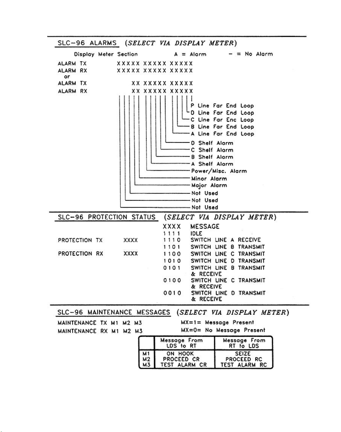
1. To view any span errors or SLC®96 alarms, press [SHIFT], [2] to enter
the meter display.
2. Press the MENU and VALUE keys to display such events as T1
levels, A/B bit states, slips, alarms, protection fields, etc.
3. Note that the A/B bit status display provides the current status of
any of the 24 timeslots, grouped in increments of 6 timeslots. These
timeslots should not be confused with channels since
channels designations are different than timeslot designations.
June 28, 1996 17
Page 23
AM8a Test Procedure Guide (18-0133) Addendum to 18-0037
June 28, 1996 18
Page 24

AM8a Test Procedure Guide (18-0133) Addendum to 18-0037
VIEW SIGNALING EVENTS (DIGITS, TONES, SEIZURES)
1. To view the signaling events decoded on a given timeslot, press
[SHIFT], [1] so that the AM8a will display all digits, off hooks, etc.
that are detected.
2. If it is desirable to capture calls on a timeslot other than channel 1
(default), press [SHIFT], [5] to enter SETUP: CONFIGURATION.
3. Press the MENU keys until the display shows:
CHAN
1
4. To select any given timeslot, enter a value of 1 to 24.
To select any given channel, enter a value of -1 to -96.
To select a random mode of operation, enter a value of 0. This allows
the AM8a to automatically scan for the next call upon the
completion of the call currently analyzed.
5. Upon selection of the desired channel, press [SHIFT], [1] to display
the call events.
MODE II OPERATION
The AM8a can also be configured to monitor MODE II (Concentrated) types of calls.
This type of operation involves having 48 subscribers (channels) vying for 24
available timeslots. In addition to performing its usual analysis, the AM8a can also
perform channel to timeslot mapping and a detailed analysis of the 4 kb datalink
messaging.
DATALINK MONITORING
1. To monitor the 4 kb datalink, it is first necessary to make the
appropriate channel selection in the AM8a.
June 28, 1996 19
Page 25

AM8a Test Procedure Guide (18-0133) Addendum to 18-0037
2. Press [SHIFT], [5] to enter the SETUP: CONFIGURATION menu.
3. Press the MENU keys until the display shows:
CHAN
1
4. Enter a channel selection of -97 to select the 4 kb datalink.
5. Press the MENU keys until the display shows:
FRAMING
SLC®96 I
6. Press the FIELD and VALUE keys until the display shows:
FRAMING
SLC®96 II
7. Press the MENU keys until the display shows:
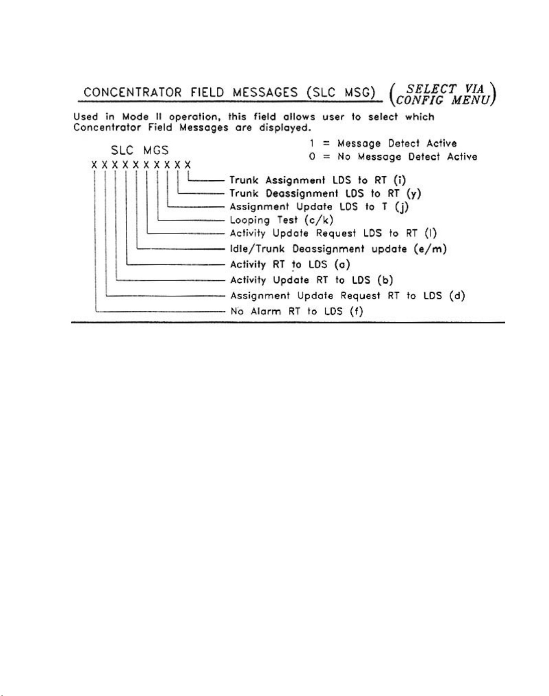
8. Using the FIELD and VALUE keys, selectively toggle on those
Concentrator Field Messages that the user desires the AM8a to
decode by changing the “0” values to a “1” value. It is suggested
that the user disable the “idle” messages as they will quickly
overrun the AM8a’s display buffer and thus prevent the user from
capturing those messages of special interest.
June 28, 1996 20
SLC® MSG
0000000001
Page 26
AM8a Test Procedure Guide (18-0133) Addendum to 18-0037
9. Once these steps are completed, press [SHIFT],[1] to display the
datalink messages.
APPLICATION NOTE #5
DS1/T1 Signal Monitoring
This application note describes the capabilities of the Ameritec Model AM8a
PCM/VF Call Analyzer to perform T1 signal monitor testing. The AM8a provides a
variety of non-intrusive PCM digital tests including transmission errors, frame
synchronization, signaling bit status and channel noise measurements. The unit is
also equipped with a digital dual multimeter for measuring level, frequency and
amplitude on selected channels and the span itself.
June 28, 1996 21
Page 27
AM8a Test Procedure Guide (18-0133) Addendum to 18-0037
Upon power-up, the AM8a will default to monitoring a T1 with E&M signaling. The
framing is set to D3/D4 and channel 1 has already been selected for monitoring. This
application note will help step the user through any changes necessary for
configuring the AM8a for circuits other than the AM8a’s default state.
SETUP PROCEDURES
1. Power up the AM8a and wait 3 seconds for self test to complete.
2. Because the AM8a powers up in a T1 monitoring configuration, place
the unit on-line by pressing [SHIFT], [KP] to toggle the INPUT LED
on. This connects the AM8a to the circuit under test.
n
n
Network Equipment
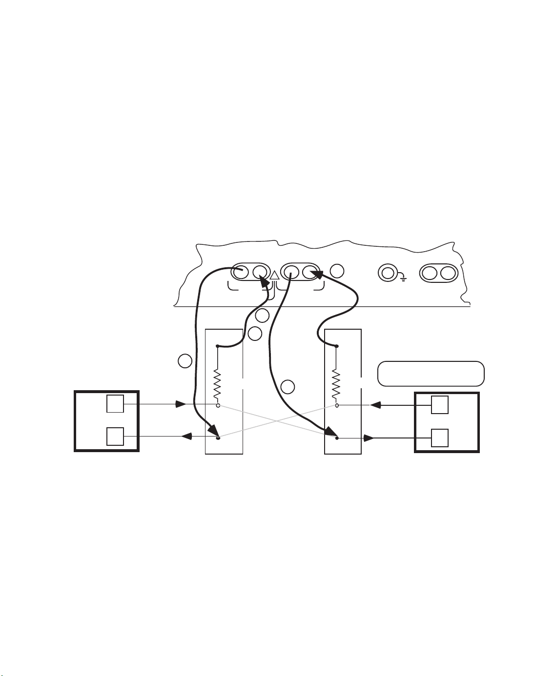
3. Connect the AM8a PCM jacks to the DSX as follows:
a. Connect the RX for PCM1 to the monitor jack of the direction that
should source timing,
TXRXTX RX
a
PCM2
CAUTION: 10 VOLTS MAX
!
PCM1
TRUNK INPUTS
c
b
MONMON
e
1500 Ω
IN
Repeat 1 to 2 or Repeat 2 to 1 connections
(IN jacks break
cross connects)
d
1500 Ω
IN
TX/2W RXA/B
LOOP TIMS
2.048Mbps clock source
for rpt 1 to 2 or rpt 2 to 1
n
n
Network Equipment
June 28, 1996 22
Page 28

AM8a Test Procedure Guide (18-0133) Addendum to 18-0037
b. Locate the monitor jack for the other direction (LED above DSX
MON JACK will be blinking) and connect the TX for PCM1 to it.
c. At this point, ABCD signaling bit LEDs on the AM8a front panel
should stop scrolling indicating frame synchronization has been
established. If these LEDs are still scrolling, the user should
check to see that either the correct framing format has been
chosen, the cables used are good or that the timing source is
connected to the PCM1 RX input jack.
IMPORTANT NOTE: The AM8a is expecting a “padded” signal into the PCM1
jacks consistent with that of a signal from a resistor isolated
monitor jack. If the monitor jacks are not resistor-isolated,
use the Ameritec resistor cables provided with the AM8a
(P/N 48-0131).
PARAMETER CHANGES
1. If it is desirable to change any of the parameters from their default
state, press [SHIFT], [5] to enter the SETUP: CONFIGURATION
menu. All parameters that control the T1 circuit types, framing, etc.
are located in this menu.
2. When in this menu, press the MENU keys to display the field to be
changed.
3. When the desired field is displayed, press the FIELD and VALUE
keys to select the appropriate field and change the parameter to
the desired value.
June 28, 1996 23
Page 29

AM8a Test Procedure Guide (18-0133) Addendum to 18-0037
METER DISPLAY (A/B BIT STATES, SPAN ERRORS, ETC.)
All T1 span measurements such as slips, frame errors, level, etc. are displayed in the
Meter Section. To access these results:
1. Press [SHIFT], [2] to enter the Meter Display.
2. Press the MENU keys to display the various span measurements
described above.
3. If it is desirable to reset any of the measurements shown on the
display, the user needs to press [SHIFT], [D] while that
measurement is displayed.
4. There are two screens in the Meter Display that may require the
user to use the FIELD and VALUE keys to select a desired
measurement. These screens are shown below:
MEASURE SCALE MEASURE SCALE
Vt-r 100 Vr-g 5
and,
NOISE 65dBrn
INPUT TX FILTER CMSG
To select values other than those shown, use the FIELD and VALUE keys to scroll
through the parameter selections.
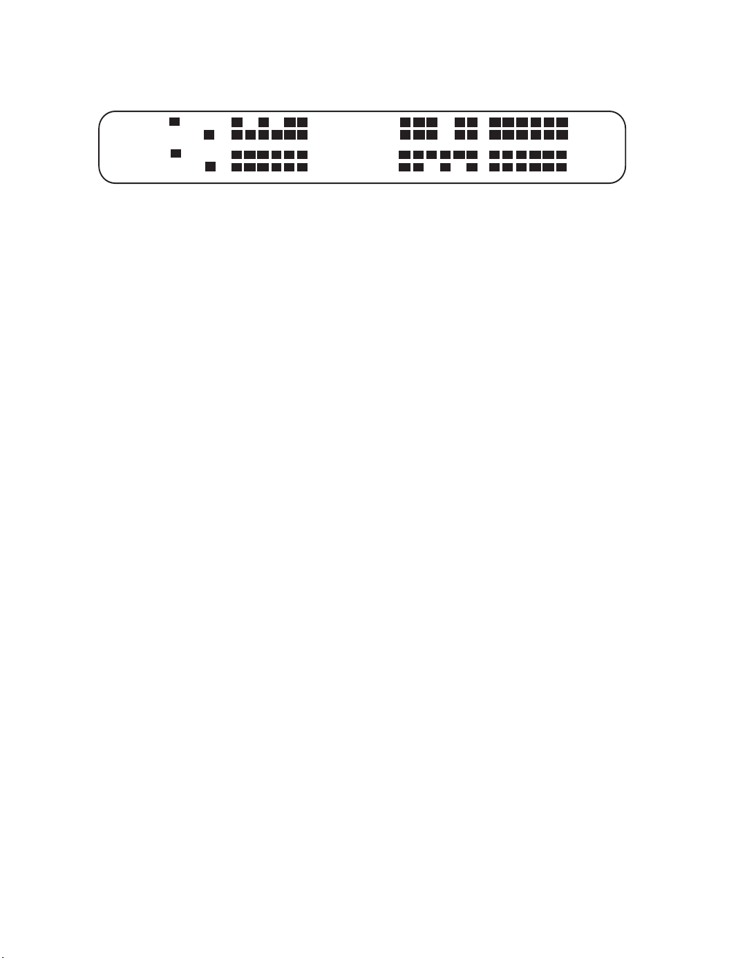
A/B SIGNALING BIT STATUS
While in the Meter Display, it is possible to view the bit states of all 24 timeslots
simultaneously. The timeslots are arranged in four groups of six and each timeslot’s
A/B bit can be monitored by viewing the rectangular LCD bars that correspond to the
TX and RX A/B bits. If an A/B bit is in an active (high) state, the LCD bar that
corresponds to that signaling bit will appear. If no LCD bar is present, then that
timeslot’s signaling bit is in an inactive (low) state. A dot will appear if neither
signaling bit is active.
June 28, 1996 24
Page 30
AM8a Test Procedure Guide (18-0133) Addendum to 18-0037
TX A B
RX A B
If the AM8a is not in a valid mode for this display, dots will appear in all bit
positions.
• • • • • •
• • • • • •
APPLICATION NOTE #6
Originating or Terminating a DS/T1 Call
The following example illustrates how the AM8a can be configured to originate or
terminate a call on one channel of a T1.
SETUP PROCEDURES
1. Power up the AM8a and wait 3 seconds for self test to complete.
2. Press [SHIFT], [5] to enter the SETUP: CONFIGURATION section.
3. Press the MENU keys until the display shows:
IMITATE MODE
switch monitor
4. Press the FIELD and VALUE keys until the display shows:
IMITATE MODE
te/line emulate
If it is desirable to terminate the call as a switch, then change the
IMITATE field to "switch”.
June 28, 1996 25
Page 31

AM8a Test Procedure Guide (18-0133) Addendum to 18-0037
To originate a call, the AM8a will only dial if the IMITATE field is
set to “te/line”. The only exception to this operation is for E&M
circuits which can dial regardless of setting since E&M circuits are
symmetrical in design.
5. Press the MENU keys until the display shows:
ANALOG IMPEDANCE ANALOG/PCM
900 ohms pcm loop clk
If it is desirable to have the AM8a source timing on the T1 circuit,
change the ANALOG/PCM setting to “pcm int clk”.
6. Press the MENU keys until the display shows:
INPUT FRAMING ZERO SUP CHAN
pcm 1 on D3/D4 AMI 1
Make any changes to the framing and zero suppression formats by
selecting each entry and pressing the VALUE keys until the desired
value is displayed. Channel selection changes can be made by
directly entering the numeric value into this field.
7. Press the MENU keys until the display shows:
TRUNK TYPE E&M TYPE
E&M 4W 1
Change the TRUNK TYPE to match the signaling of the T1 you are
working with (E&M 4W, DID, Loop Start, Ground Start). For FX
signaling, select “loop” or “ground” and use the IMITATE selection
in Step 4 to change from FXO (“switch”) to FXS (“te/line”).
If signaling formats other than these are used, press the MENU
down [C] key, until the display shows:
PCM Off HK a/b On HK a/b
Config2 auto auto
June 28, 1996 26
Page 32

AM8a Test Procedure Guide (18-0133) Addendum to 18-0037
Use the Field and Value keys to select the desired on hook and off
hook states. These states include auto, 0/0, 0/1, 1/1, 0/X, 1/X, X/0
and X/1, where X denotes a don’t care state.
Any selections made here will override previous selections made in
the trunk configuration display. To return to any of the standard
selections in the trunk configuration display, reset both the “off
hook” and “on hook” fields in the PCM Config2 display to “auto”.
8. Press the MENU keys until the display shows:
LOOP TYPE START SIGNAL
pulse wink
Use the FIELD and VALUE keys to change the LOOP TYPE to the
type of dialing you will use: DTMF, Dial Pulse or MF(R1). Use the
same procedure to select the proper start signal for the circuit: Wink,
Immediate, Delay or Dial tone. Note: MF(R1) is normally used on
E&M trunks and pulse/DTMF are normally used on loop and ground
trunks.
9. Dialing digits on a channel can be accomplished on the AM8a either
by using the AUTO DIAL mode or by dialing manually from the
keypad.
To enter the AUTO DIAL field, simply press [SHIFT], [8]. Up to 10
dialing sequences can be stored. Press the MENU up/down keys to
scroll to an unused dialing field or write over an existing field. Enter
digits into the field from the keypad. The dialing sequence shown
on the display will be the one used for the AUTO DIAL.
OPERATION
1. Press [SHIFT], [1] so that the AM8a will display the call.
2. Press [SHIFT], [KP] to toggle the INPUT LED ON. This connects the
AM8a to the circuit under test.
June 28, 1996 27
Page 33

AM8a Test Procedure Guide (18-0133) Addendum to 18-0037
3. Now connect the AM8a to the T1 transmit and receive jacks. When
frame sync is established the ABCD LEDs will stop scrolling and
the LEDs will indicate channel conditions. Also the status LEDs
will show the trunk selection, whether the unit is emulating switch
or terminal/line and if the PCM1 or PCM2 jacks on the AM8a has
been selected.
4. Press [SHIFT], [AUTO] to automatically enable the auto dial
feature if desirable. Otherwise, manually dial each digit by
pressing the appropriate numbers on the front panel.
TERMINATING AN INBOUND CALL
1. To terminate an inbound call:
A capital “H” on the display indicates a seizure for E&M or DID
signaling whereas a capital “R” on the display indicates a seizure
(ringing) for FX signaling. Press the SEIZE key to answer the call.
ORIGINATING A CALL
1. To originate a call, press the SEIZE key to generate an OFF Hook
(shown as a capital “H”)
2. If the AM8a is in the AUTO DIAL mode, the AM8a will
automatically outpulse the digits upon receiving the programmed
start dial.
3. If not in the AUTO DIAL mode, when the start signal is received
(dial tone for FX and typically a wink for E&M/DID), digits can be
outpulsed manually by pressing the keys directly.
4. To go back On Hook, press the SEIZE key again (small “h” is
displayed).
June 28, 1996 28
Page 34

AM8a Test Procedure Guide (18-0133) Addendum to 18-0037
APPLICATION NOTE #7
Digit Analysis and Exception Reporting
The following example illustrates how the AM8a monitors dialed digits and reports
exceptions based on preset thresholds. Exceptions can be shown via both the display
and printout. This application note assumes the user has already configured the
AM8a for proper trunk type, start signal, etc.
SETUP PROCEDURES
1. Press [SHIFT], [5] to enter the SETUP: CONFIGURATION section.
2. Press the MENU keys until the display shows:
MODE DIG DET
new call reset narrow
3. The DIGIT DETECT field defines the way in which the AM8a will
display or print dialed digit events. The default state of "narrow"
will result in the AM8a displaying/printing those dialed digits
that are exceptions to the expected values or are within
expected values. The "wide" selection results in all dialed digits
including those that are unrecognizable being displayed/printed.
The "limit" selection results in only those dialed digits that meet
the pre-set thresholds being displayed or printed.
4. Press the MENU keys until the display shows:
AUTOPRINT
off
5. Press the VALUE keys until the appropriate selection is made
(flawed calls, events only or flawed calls, events & details) that
determines whether the AM8a prints out the corresponding analysis
information for each digit detected.
June 28, 1996 29
Page 35

AM8a Test Procedure Guide (18-0133) Addendum to 18-0037
6. Press the MENU keys until the display shows:
BAUD RATE PARITY CR DELAY
9600 none 0
Press the FIELD and VALUE keys to select the appropriate values
that match your printer settings.
CONFIGURING ANALYZE THRESHOLDS
1. Press [SHIFT], [7] to enter ANALYZE menu.
2. Press the MENU keys until the display shows:
SPEEDpps(min/max) BREAK%
8.0 12.0 50 70
Use the FIELD and VALUE keys to select each parameter and make
any changes to the default values. The ranges shown indicate that a
dial pulse digit detected within these values will be a "good" digit
with respect to speed and break.
3. Press the MENU keys until the display shows:
INTRDIGIT ms(min)
300
Use the VALUE keys to change the interdigit timing in one (1)
millisecond increments. The value selected will represent the
minimum value of interdigit timing that is acceptable for a "good"
digit.
4. Press the MENU keys until the display shows:
LO BAND dB(min/max) HI BAND dB
-15 -3 -15 -3
Use the FIELD and VALUE keys to select each parameter and make
any changes to the default values. These values apply both to
DTMF and MF (R1) levels for both the low and high band signals
and represent the value that a digit must fall within to be
considered "good".
June 28, 1996 30
Page 36

AM8a Test Procedure Guide (18-0133) Addendum to 18-0037
5. Press the MENU keys until the display shows:
FREQ % (max) TWIST dB (min/max)
1.5 -6 6
Use the FIELD and VALUE keys to select each parameter and make
any changes to the default values. These values apply both to
DTMF and MF (R1) digits. The FREQ field represents the maximum
amount of frequency deviation allowed for a "good" digit's low band
or high band frequency component. The TWIST field represents the
difference between the low band level and high band level of a
digit.
6. Press the MENU keys until the display shows:
TONE ON/OFF ms(min) GUARD ms
35 35 20
Use the FIELD and VALUE keys to select each parameter and make
any changes to the default values.
The TONE field represents the minimum on-time and off-time that
each digit must be present and quiet, respectively to be a "good"
digit.
The GUARD field is important because it is used to determine the
minimum on-time that a digit must be present before the AM8a will
analyze it. Any event shorter than the GUARD time will be ignored
by the AM8a regardless of how any other parameter is programmed.
OPERATION
1. Press [SHIFT], [1] so that the AM8a will display the call.
2. Press [SHIFT], [KP] to toggle the INPUT LED on. This connects the
AM8a to the circuit under test.
3. Now connect the AM8a to the circuit under test.
June 28, 1996 31
Page 37

AM8a Test Procedure Guide (18-0133) Addendum to 18-0037
DISPLAYING EXCEPTIONS
1. To display exceptions on hard-copy printout, connect the AM8a's
RS232 port to a serial ASCII printer. As errored calls are detected,
the information will print out automatically to the printer based on
those settings configured in this application note.
2. To determine whether a call has an errored digit when no printer is
available, the user can view the display to determine the errored
event.
To accomplish this, the user should place the display marker
(underline) under the "greater than sign". If an errored event has
occurred, the bottom display line will blink.
The user can then move the display marker from event to event until
the user encounters a blinking value on the bottom line. That
blinking value indicates the parameter that has fallen out of the
range of the pre-set analyze thresholds.
June 28, 1996 32
Page 38

Ameritec is dedicated to serving the worldwide
telecommunications community by providing
competitively priced, state-of-the-art test equipment
that is supported by the finest in marketing,
engineering development and customer service.
760 Arrow Grand Circle
Covina, CA 91722 USA
TEL 626.915.5441
FAX 626.915.7181
www.ameritec.com
 Loading...