

Page 1
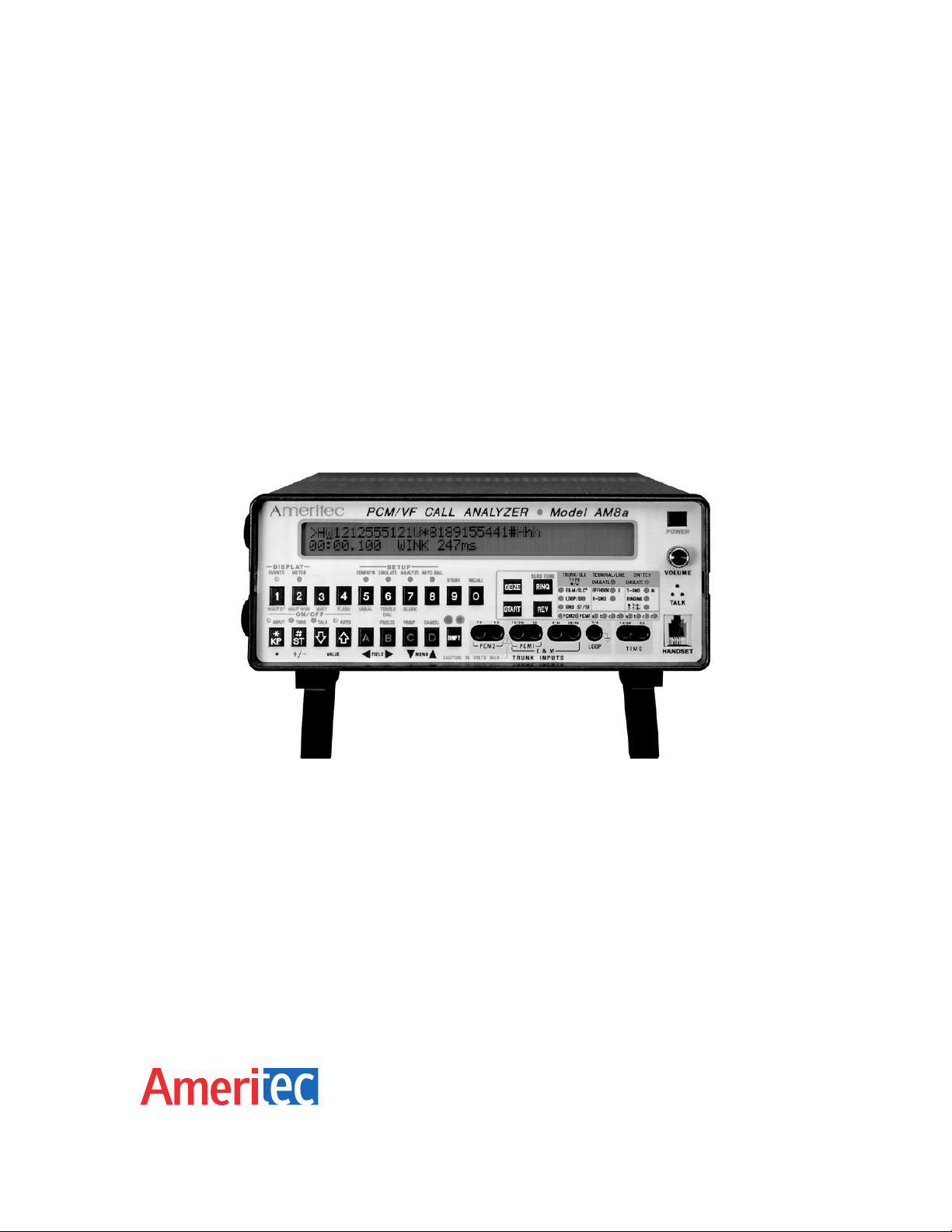
MODEL AM8a
PCM/VF CALL ANALYZER
INSTRUCTION MANUAL
Page 2

Model AM8a
PCM/VF CALL ANALYZER
INSTRUCTION MANUAL
February 10, 2000
Technical Data Subject to
Change without Notice
For extra copies of this
manual, order Part
No. 18-0037 © 2000 Ameritec Corporation
Page 3

AM8a Instruction Manual (18-0037) CAUTION/REVISIONS
When using the padded carrying case for the AM8a (P/N 87-0070C), DO NOT PLACE the power cord
around the side of the AM8a in the manner demonstrated in Figure 1.
Instead, be certain to WIND THE CORD UNDER THE CASING in the area between the feet, as shown in Figure
2.
Failure to follow this procedure could cause deterioration of the cord and increase the possibility of electric
shock.
AM8a
(Bottom of Casing)
AM8a
(Top of Casing)
Rear Panel
Bracket
Figure 1 — WRONG Figure 2 — CORRECT
Record of Revisions
December 1991 Original Issue.
February 1992 General data revision.
August 1992 Software upgrade. General format change and reprint.
January 1993 General data revision.
May 1993 Changed listing fonts. Reformatted. Corrected RX connections.
March 1994 General corrections and additions. Added Test Procedure Guide.
October 1994 Logo change. Test Procedure Guide removed.
May 1995 Added Warranty, Calibration, and Repair info.
August 1996 Added E-Mail Address to logos.
K December 2, 1999 Changed GUARDms value for DTMF/MF ANALYZE 3.
L February 10, 2000 Reformatted entire manual and added MF(R1) note.
December 2, 1999 0037-TPG.L_18
ii
Page 4

AM8a Instruction Manual (18-0037) Table of Contents
Table of Contents
1. FRONT PANEL OPERATION....................................................................................................1-1
1.1 FRONT PANEL PROGRAMMING METHODS....................................................................1-1
1.1.1 SHIFT Key.....................................................................................................................1-1
1.1.2 Arrow Keys....................................................................................................................1-2
1.2 EVENTS AND METER KEYS AND DISPLAY..................................................................... 1-3
1.2.1 EVENTS ([SHIFT][1]) Key.............................................................................................1-3
1.2.2 Events Display Character Set.......................................................................................1-4
1.2.3 Dialed Digits.................................................................................................................. 1-7
1.2.4 METER ([SHIFT][2]) Key..............................................................................................1-7
1.3 SETUP AREA.......................................................................................................................1-8
1.3.1 CONFIG’N ([SHIFT][5]) Key..........................................................................................1-8
1.3.2 EMULATE ([SHIFT][6]) Key..........................................................................................1-8
1.3.3 ANALYZE ([SHIFT][7]) Key...........................................................................................1-8
1.3.4 AUTO DIAL ([SHIFT][8]) Key........................................................................................1-8
1.4 CONTROL ON/OFF KEYS...................................................................................................1-9
1.4.1 INPUT ([SHIFT][*, KP]) Key..........................................................................................1-9
1.4.2 TIMS ([SHIFT][#, ST]) Key............................................................................................ 1-9
1.4.3 TALK ([SHIFT][
1.4.4 AUTO ([SHIFT][
1.5 MENU/DATA CONTROL KEYS.........................................................................................1-10
1.5.1 FREEZE ([SHIFT][B]) Key..........................................................................................1-10
1.5.2 PRINT ([SHIFT][C]) Key..............................................................................................1-11
1.5.3 CANCEL ([SHIFT][D] Key...........................................................................................1-11
1.6 SIGNALING KEYS.............................................................................................................1-11
1.6.1 SEIZE Key...................................................................................................................1-11
1.6.2 START Key.................................................................................................................1-12
1.6.3 RING Key....................................................................................................................1-12
1.6.4 REV Key......................................................................................................................1-12
1.6.5 SEND TONE ([SHIFT][RING]) Key............................................................................. 1-12
VALUE
VALUE
]) Key.................................................................................1-10
]) Key................................................................................1-10
0037-TOC.L_58 February 10, 2000
iii
Page 5

Table of Contents (18-0037) AM8a Instruction Manual
1.7 DATA ENTRY KEYS FOR SIGNALING.............................................................................1-13
1.7.1 WAIT DT ([SHIFT][SHIFT][1] Key...............................................................................1-13
1.7.2 WAIT WINK ([SHIFT][SHIFT][2] Key..........................................................................1-13
1.7.3 WAIT ([SHIFT][SHIFT][3] Key.....................................................................................1-13
1.7.4 FLASH ([SHIFT][SHIFT][4] Key..................................................................................1-13
1.7.5 UNBALANCE ([SHIFT][SHIFT][5] Key........................................................................1-13
1.7.6 TOGGLE DIAL ([SHIFT][SHIFT][6] Key......................................................................1-13
1.7.7 BLANK ([SHIFT][SHIFT][7] Key..................................................................................1-13
1.8 SIGNALING STATUS LEDs...............................................................................................1-14
1.9 STORE SETUP..................................................................................................................1-15
1.10 RECALL SETUPS............................................................................................................1-16
1.10.1 RECALL Setup Parameters......................................................................................1-16
1.10.2 RECALL Auto Dial Sequence...................................................................................1-16
1.11 SPEAKERPHONE/AUDIO MONITOR.............................................................................1-16
1.11.1 Speakerphone in talk mode......................................................................................1-16
1.11.2 Handset.....................................................................................................................1-17
1.11.3 Audio Monitoring.......................................................................................................1-17
2. CONFIGURATION PARAMETERS...........................................................................................2-1
2.1 MODE CONFIG....................................................................................................................2-1
2.1.1 IMITATE........................................................................................................................ 2-1
2.1.2 MODE............................................................................................................................2-1
2.2 CIRCUIT CONFIG................................................................................................................2-2
2.2.1 ANALOG IMPEDANCE.................................................................................................2-2
2.2.2 ANALOG/PCM..............................................................................................................2-2
2.3 PCM CONFIG 1 and PCM CONFIG 2.................................................................................2-3
2.3.1 INPUT............................................................................................................................2-3
2.3.2 FRAMING...................................................................................................................... 2-4
2.3.3 ZERO SUP....................................................................................................................2-4
2.3.4 CHAN............................................................................................................................2-5
2.3.5 OFF HK a/b or ON HK a/b............................................................................................2-5
February 10, 2000 0037-TOC.L_
iv
Page 6

AM8a Instruction Manual (18-0037) Table of Contents
2.4 TRUNK CONFIG..................................................................................................................2-5
2.4.1 TRUNK TYPE...............................................................................................................2-6
2.4.2 SLC® TYPE..................................................................................................................2-6
2.4.3 E & M TYPE.................................................................................................................. 2-6
2.5 DISPLAY CONFIG 1 and CONFIG 2................................................................................... 2-7
2.5.1 MODE............................................................................................................................2-7
2.5.2 DIGit DETection............................................................................................................2-8
2.5.3 SLC® MSG...................................................................................................................2-8
2.5.4 SLC® Activity Message................................................................................................2-9
2.5.5 T/t Mask (single-tone event selection)..........................................................................2-9
2.6 RS232 CONFIG....................................................................................................................2-9
2.6.1 BAUD RATE..................................................................................................................2-9
2.6.2 PARITY.......................................................................................................................2-10
2.6.3 CR DELAYsec.............................................................................................................2-10
2.7 SECURITY CONFIG..........................................................................................................2-10
2.7.1 PASSWORD...............................................................................................................2-10
2.7.2 SETUP PROTECT......................................................................................................2-10
2.8 PRINT CONFIG..................................................................................................................2-11
2.8.1 off................................................................................................................................2-11
2.8.2 all calls, events only....................................................................................................2-11
2.8.3 all calls, events & details............................................................................................. 2-11
2.8.4 flawed calls, events only.............................................................................................2-11
2.8.5 flawed calls, events & details......................................................................................2-11
2.9 CLOCK CONFIG................................................................................................................2-12
2.10 AM8a CONFIG.................................................................................................................2-12
3. EMULATE PARAMETERS........................................................................................................3-1
3.1 LOOP EMULATE..................................................................................................................3-1
3.1.1 VOLTAGE.....................................................................................................................3-1
3.1.2 LENGTH........................................................................................................................ 3-1
0037-TOC.L_58 February 10, 2000
v
Page 7

Table of Contents (18-0037) AM8a Instruction Manual
3.2 TERMINATION EMULATE...................................................................................................3-1
3.2.1 2.16uf............................................................................................................................3-1
3.2.2 DC HOLD...................................................................................................................... 3-2
3.3 DIALING EMULATE.............................................................................................................3-2
3.3.1 LOOP TYPE..................................................................................................................3-2
3.3.2 START SIGNAL............................................................................................................3-2
3.4 PULSE EMULATE................................................................................................................ 3-2
3.4.1 SPEEDpps....................................................................................................................3-2
3.4.2 BREAK%....................................................................................................................... 3-2
3.4.3 INTRDIGITms...............................................................................................................3-2
3.5 DTMF/MF EMULATE 1........................................................................................................3-3
3.5.1 HI:dBm/hz%.................................................................................................................. 3-3
3.5.2 LO:dBm/hz%.................................................................................................................3-3
3.6 DTMF/MF EMULATE 2........................................................................................................3-3
3.6.1 ON/OFFms.................................................................................................................... 3-3
3.7 SEND TONE EMULATE.......................................................................................................3-4
3.7.1 LEVELdBm....................................................................................................................3-4
3.7.2 FREQUENCYhz............................................................................................................3-4
3.8 DIAL TONE EMULATE 1......................................................................................................3-4
3.9 DIAL TONE EMULATE 2......................................................................................................3-4
3.9.1 T1:dBm/hz..................................................................................................................... 3-5
3.9.2 T2:dBm/hz..................................................................................................................... 3-5
3.9.3 DL SNDms....................................................................................................................3-5
3.10 RECALL EMULATE............................................................................................................3-5
3.10.1 HOOKFLASHms......................................................................................................... 3-5
3.10.2 LINE UNBALms..........................................................................................................3-5
3.11 RINGING EMULATE 1....................................................................................................... 3-6
3.11.1 ON/OFFms.................................................................................................................. 3-6
3.12 RINGING EMULATE 2....................................................................................................... 3-6
3.12.1 VOLTAGEvrms...........................................................................................................3-6
3.12.2 FREQUENCYhz..........................................................................................................3-6
February 10, 2000 0037-TOC.L_
vi
Page 8

AM8a Instruction Manual (18-0037) Table of Contents
3.13 START TIME EMULATE.................................................................................................... 3-7
3.13.1 DLY:BGN/ENDms....................................................................................................... 3-7
3.13.2 WINK:BGN/DURms....................................................................................................3-7
3.14 SF EMULATE..................................................................................................................... 3-7
3.14.1 LEVEL.........................................................................................................................3-7
3.14.2 FREQ+%hz.................................................................................................................3-7
4. ANALYSIS PARAMETERS........................................................................................................4-1
4.1 HOOK ANALYZE..................................................................................................................4-1
4.1.1 FLASHms(min)..............................................................................................................4-1
4.1.2 DISCONNECTms(min).................................................................................................4-1
4.2 STRT SIG (START SIGNAL) ANALYZE: EXPECTED TYPE..............................................4-2
4.2.1 dialtone/wink.................................................................................................................4-2
4.2.2 dialtone/delay................................................................................................................4-2
4.2.3 dialtone/…..................................................................................................................... 4-2
4.3 DT STRT (DIALTONE START) ANALYZE: DIALTONE RCVDms (min/max).....................4-2
4.4 DLY STRT (DELAY START) ANALYZE..............................................................................4-3
4.4.1 STRT BGNms(min/max)...............................................................................................4-3
4.4.2 ENDms(min)..................................................................................................................4-3
4.5 WINK STRT..........................................................................................................................4-3
4.5.1 WINK BGNms(min).......................................................................................................4-3
4.5.2 DURms(min/max)..........................................................................................................4-3
4.6 PULSE ANALYZE 1.............................................................................................................4-4
4.6.1 SPEEDpps(min/max).................................................................................................... 4-4
4.6.2 BREAK%.......................................................................................................................4-4
4.7 PULSE ANALYZE 2.............................................................................................................4-4
4.7.1 INTERDIGITms(min)..................................................................................................... 4-4
4.8 DTMF/MF ANALYZE 1.........................................................................................................4-5
4.8.1 LO BANDdB(min/max)..................................................................................................4-5
4.8.2 HI BANDdB...................................................................................................................4-5
0037-TOC.L_58 February 10, 2000
vii
Page 9

Table of Contents (18-0037) AM8a Instruction Manual
4.9 DTMF/MF ANALYZE 2.........................................................................................................4-5
4.9.1 FREQ%(max)................................................................................................................4-6
4.9.2 TWISTdB(min/max).......................................................................................................4-6
4.9.3 DTMF Frequencies.......................................................................................................4-6
4.9.4 MF(R1) Frequencies..................................................................................................... 4-7
4.10 DTMF/MF ANALYZE 3.......................................................................................................4-8
4.10.1 TONE ON/OFFms(min)..............................................................................................4-8
4.10.2 GUARDms...................................................................................................................4-8
4.11 THRESHOLD ANALYZE....................................................................................................4-8
4.11.1 TONEdBm(min)...........................................................................................................4-8
4.11.2 OFF HKvdc(min)......................................................................................................... 4-9
4.11.3 Procedure to Set OFF HKvdc(min) Threshold............................................................4-9
5. AUTO AND MANUAL DIALING ................................................................................................ 5-1
5.1 STORE AUTODIAL SEQUENCE......................................................................................... 5-1
5.2 SELECT AND USE AUTODIAL SEQUENCE......................................................................5-2
5.3 MANUAL DIALING...............................................................................................................5-2
6. METER DISPLAY........................................................................................................................6-1
6.1 MEASURE/SCALE MENU...................................................................................................6-1
6.2 MEASURE DISPLAY (MAKING MEASUREMENTS)..........................................................6-1
6.3 METER SELECTIONS AND CONNECTIONS.....................................................................6-2
6.4 LOOP START, GROUND START, DID – ANALOG MEASURE......................................... 6-7
6.4.1 V t-r dc or ac..................................................................................................................6-7
6.4.2 V cm dc or ac................................................................................................................6-7
6.4.3 V t-g dc or ac.................................................................................................................6-7
6.4.4 V r-g dc or ac.................................................................................................................6-7
6.4.5 It(mA) dc........................................................................................................................ 6-7
6.4.6 Tone..............................................................................................................................6-8
February 10, 2000 0037-TOC.L_
viii
Page 10

AM8a Instruction Manual (18-0037) Table of Contents
6.5 E & M and SF – ANALOG MEASURE.................................................................................6-9
6.5.1 TX Vt-r or RX Vt-r, dc or ac........................................................................................... 6-9
6.5.2 TX Vcm or RX Vcm, dc or ac........................................................................................6-9
6.5.3 Ve or Vm, dc or ac........................................................................................................6-9
6.5.4 Vsb or Vsg, dc or ac....................................................................................................6-10
6.5.5 TX Tone or RX Tone...................................................................................................6-10
6.6 E & M and SF – ANALOG MEASURE...............................................................................6-11
6.6.1 TX1 Vcm or TX2 Vcm, dc or ac..................................................................................6-11
6.6.2 RX1 Vcm or RX2 Vcm, dc or ac.................................................................................6-11
6.6.3 TX1 Tone or TX2 Tone...............................................................................................6-11
6.6.4 RX1 Tone or RX2 Tone..............................................................................................6-12
6.6.5 RX1 dBdsx or RX2 dBdsx...........................................................................................6-12
6.6.6 RX1 dBdsx or RX2 dBdsx in Emulation Mode............................................................6-12
6.6.7 RX1 dBdsx or RX2 dBdsx in Monitor Mode................................................................6-12
6.7 NOISE MEASURE..............................................................................................................6-12
6.8 PCM1 and PCM 2 BIPOLAR VIOLATION (COUNT AND STATUS) MEASURE..............6-13
6.8.1 BPV.............................................................................................................................6-13
6.8.2 FERR...........................................................................................................................6-14
6.8.3 CRC.............................................................................................................................6-14
6.8.4 SLIPS..........................................................................................................................6-14
6.8.5 YELLOW.....................................................................................................................6-14
6.8.6 BLUE...........................................................................................................................6-14
6.8.7 STATUS BLUE............................................................................................................6-14
6.8.8 STATUS YELLOW......................................................................................................6-14
6.9 PCM 1 OR PCM 2 FRAME SYNC MEASURE..................................................................6-14
6.10 PCM1 and PCM 2 TX OR RX A/B MEASURE................................................................6-15
6.10.1 T1 Time-Slot to Voice Channel Assignment.............................................................6-15
6.10.2 SLC®96 Mode I Time-Slot to Voice Channel Assignment.......................................6-15
6.10.3 SLC®96 Mode II Time-Slot to Voice Channel Assignment......................................6-15
0037-TOC.L_58 February 10, 2000
ix
Page 11

Table of Contents (18-0037) AM8a Instruction Manual
6.11 SLC®96 MODE I OR II MESSAGES...............................................................................6-17
6.11.1 ALARM TX or RX......................................................................................................6-17
6.11.2 PROTECTION TX or RX...........................................................................................6-18
6.11.3 MAINTENANCE TX or RX........................................................................................6-18
6.11.4 SLC®96 II Concentrator Field Messages.................................................................6-19
7. RS232 ENTRIES AND PRINTOUTS..........................................................................................7-1
7.1 RS232 COMMAND DESCRIPTION.....................................................................................7-1
7.1.1 Terminal Commands.....................................................................................................7-2
7.1.2 Printer Commands........................................................................................................ 7-2
7.1.3 Setup Menu Commands for CONFIG, EMULATE, and ANALYZE..............................7-2
7.1.3.1 Display Menu.........................................................................................................7-3
7.1.3.2 Change Parameter................................................................................................ 7-3
7.1.3.3 Print Menu.............................................................................................................7-3
7.1.4 AUTO DIAL Setup Commands..................................................................................... 7-3
7.1.5 ON-OFF (Control Toggle) Commands..........................................................................7-4
7.1.6 CALL INITIATE (Signaling) Commands.......................................................................7-4
7.1.7 EVENTS DISPLAY Commands....................................................................................7-4
7.1.8 METER DISPLAY Commands...................................................................................... 7-4
7.2 PRINTOUTS.......................................................................................................................7-16
7.2.1 off................................................................................................................................7-16
7.2.2 all calls, events only....................................................................................................7-16
7.2.3 all calls, events & details............................................................................................. 7-17
7.2.4 flawed calls, events only.............................................................................................7-17
7.2.5 flawed calls, events & details......................................................................................7-17
7.2.6 Manual Short Print......................................................................................................7-18
7.2.7 Manual Long Print.......................................................................................................7-19
7.3 RS232 REAR-PANEL CONNECTIONS.............................................................................7-22
7.3.1 Printer Cable (48-0084) Connection...........................................................................7-22
7.3.2 Chaining Cable (48-0083) Connection.......................................................................7-23
7.3.3 Chained Unit Addressing Command..........................................................................7-23
February 10, 2000 0037-TOC.L_
x
Page 12

AM8a Instruction Manual (18-0037) Table of Contents
8. AM8a TECHNICAL SPECIFICATIONS..................................................................................... 8-1
9. WARRANTY, SERVICE, AND CALIBRATION......................................................................... 9-1
9.1 WARRANTY......................................................................................................................... 9-1
9.2 SERVICE POLICY................................................................................................................9-1
9.3 CALIBRATION POLICY.......................................................................................................9-1
9.4 RETURN OF UNIT...............................................................................................................9-2
A. APPENDIX A: METER DISPLAY.............................................................................................A-1
A.1 PCM Operations and Data Flow..........................................................................................A-1
A.1.1 MODE CONFIG Menu Settings....................................................................................A-1
A.1.2 CIRCUIT CONFIG Menu Settings................................................................................A-6
A.1.3 PCM CONFIG 1 and CONFIG 2 Menu Settings..........................................................A-7
A.1.4 TRUNK CONFIG Menu Settings..................................................................................A-9
A.1.5 DISPLAY CONFIG Menu Settings...............................................................................A-9
A.1.6 EMULATE Menu Settings.............................................................................................A-9
A.1.7 ANALYZE Menus..........................................................................................................A-9
A.2 PCM Connection Diagrams...............................................................................................A-10
A.2.1 Monitoring Connections..............................................................................................A-10
A.2.2 ANALYZE Menus........................................................................................................A-10
0037-TOC.L_58 February 10, 2000
xi
Page 13

Table of Contents (18-0037) AM8a Instruction Manual
February 10, 2000 0037-TOC.L_
xii
Page 14

AM8a Instruction Manual (18-0037) Table of Contents
List of Figures
Figure 1-1. AM8a Front Panel.........................................................................................................1-1
Figure 1-2. AM8a Events Display...................................................................................................1-4
Figure 1-3. Signaling Status LEDs................................................................................................1-14
Figure 6-1. Cables for AM8a Front Panel Test/Meter Connections...............................................6-3
Figure 6-2. Loop/Ground Start and DID Analog Test/Meter Front Panel Connections..................6-4
Figure 6-3. E & M and SF Test/Meter Front Panel Connections....................................................6-5
Figure 6-4. PCM T1/SLC®96 Test/Meter Front Panel Connections.............................................. 6-6
Figure 6-5. SLC®96 Mode 1 Channel Number to Time Slot Assignments..................................6-16
Figure 6-6. SLC®96 Alarm Conditions Meter Display..................................................................6-17
Figure 6-7. SLC®96 Alarm Conditions Meter Display..................................................................6-18
Figure 6-8. SLC®96 Alarm Conditions Meter Display..................................................................6-18
Figure 7-1. Event-only Printout.....................................................................................................7-16
Figure 7-2. Events & Details Printout (Monitor Mode)..................................................................7-17
Figure 7-3. Events & Details Printout (Emulate Mode).................................................................7-18
Figure 7-4. Manual Short Print (Meter Display Example).............................................................7-18
Figure 7-5. Manual Short Print (EMULATE Analog Switch, Te, PCM Examples)........................7-19
Figure 7-6. Manual Long Print (Meter Display Example).............................................................7-20
Figure 7-7. Manual Long Print (Setup Example).......................................................................... 7-21
Figure 7-8. AM8a Rear Panel Connections..................................................................................7-24
Figure 7-9. RS232 Printer Cable..................................................................................................7-25
Figure 7-10. RS232 Chaining Cable.............................................................................................7-25
0037-TOC.L_58 February 10, 2000
xiii
Page 15

Table of Contents (18-0037) AM8a Instruction Manual
Figure A-1. Monitor PCM Processing Diagram..............................................................................A-2
Figure A-2. Emulate PCM Processing Diagram.............................................................................A-3
Figure A-3. Rpt (Repeat) 1 to 2 PCM Processing Diagram............................................................A-4
Figure A-4. Rpt (Repeat) 2 to 1 PCM Processing Diagram............................................................A-5
Figure A-5. Monitor PCM Connection Points..................................................................................A-6
Figure A-6. Emulate and Repeat (Drop and Insert) PCM Connections.........................................A-7
February 10, 2000 0037-TOC.L_
xiv
Page 16

AM8a Instruction Manual (18-0037) Table of Contents
List of Tables
Table 7-1. RS232 Terminal Commands......................................................................................... 7-4
Table 7-2. RS232 Printing Commands...........................................................................................7-5
Table 7-3. RS232 CONFIGuration Menu Commands....................................................................7-6
Table 7-4. RS232 EMULATE Menu Commands............................................................................7-9
Table 7-5. RS232 ANALYZE Menu Commands...........................................................................7-10
Table 7-6. RS232 Auto Dial Setup Commands............................................................................7-12
Table 7-7. RS232 On-Off (Control Toggle) Commands...............................................................7-13
Table 7-8. RS232 Call Initiate (Signaling) Commands.................................................................7-13
Table 7-9. RS232 Events Display Commands.............................................................................7-14
Table 7-10. RS232 Meter Display Commands (Analog Voltage Measurements)........................7-14
Table 7-11. RS232 Meter Display Commands (Meter Selections)..............................................7-14
Table 7-12. RS232 Meter Display Commands (PCM Measurements)........................................7-15
Table 7-13. RS232 Meter Display Commands (Noise Measurements).......................................7-16
0037-TOC.L_58 February 10, 2000
xv
Page 17

Table of Contents (18-0037) AM8a Instruction Manual
February 10, 2000 0037-TOC.L_
xvi
Page 18
AM8a Instruction Manual (18-0037) Front Panel Operation
1. FRONT PANEL OPERATION
1.1 FRONT PANEL PROGRAMMING METHODS
The following sub-sections describe the basic methods for programming the AM8a through
the front panel. Refer to Sections 2 through 6 for details on the parameters which may be
entered. Refer to Section 7 for the RS232 Commands that provide the means to duplicate front
panel operations from a terminal. (Figures 7-3 through 7-5 may also be used as a quickreference to CONFIGURE, EMULATE, and ANALYZE menu parameter descriptions.)
Ameritec
PCM/VF CALL ANALYZER
>HX9x155441XxXxHTthh
Model AM8a
POWER
11:25:08 10-19-94 Emulate Switch
DISPLAY
EVENTS
METER
1 2 3
WAIT WINK
WAIT DT
ON / OFF
INPUT
TIMS
#
*
KP
ST
+ / -
WAIT
TALK
CONFIG'N
4
FLASH
AUTO
VALUE
SETUP
EMULATE
5 6 7
UNBAL
TOGGLE
DIAL
FREEZE
A B C
FIELD
ANALYZE
BLANK
PRINT
MENU
AUTO DIAL
8
CANCEL
D
STORE
RECALL
0
9
SHIFT
CAUTION: 10 VOLTS MAX
TX RX
PCM2
SEIZE
START
TX/2W
!
PCM1
TRUNK INPUTS
SEND TONE
RING
REV
RX
E & M
TRUNK /SLC
TYPE
/
E&M/SLC
LOOP/DID
GND ST/SF
PCM2
E/M
SB/SG
TERMINAL/LINE
PCM1
LOOP
EMULATE
OFFHOOK
R-GND
a b
T/R
SWITCH
T+R–
T–R+
TIMS
VOLUME
M
TALK
RX
HANDSET
EMULATE
E
T-GND
RINGING
a b c d
c
d
TX/2W
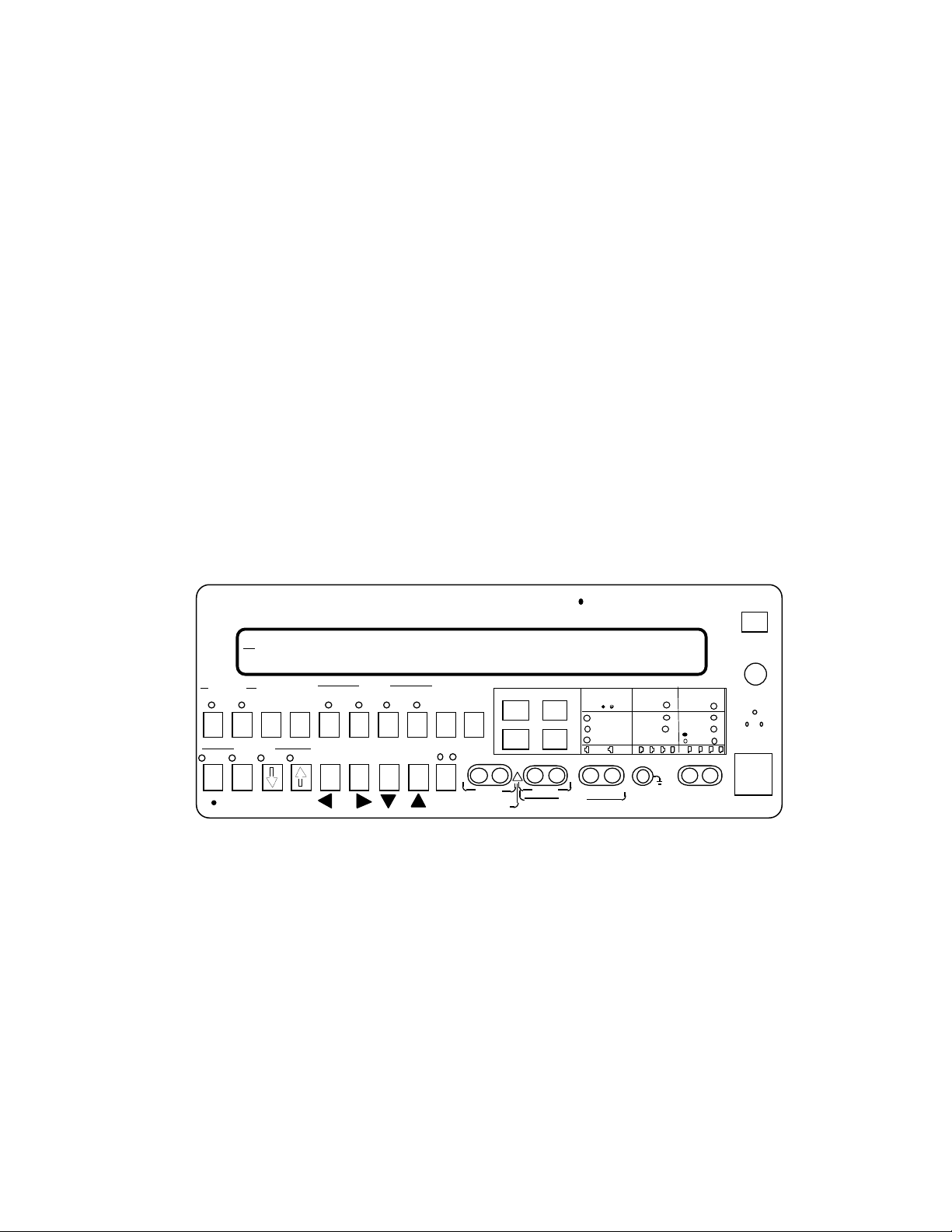
Figure 1-1. AM8a Front Panel
1.1.1 The SHIFT Key: Some keys may have as many as three separate functions. The SHIFT
key (see figure 1-1) controls access to each one of these.
• The No-Shift (or "Data Entry") functions for each key are either listed on the
center of the key itself (e.g. 1 through 0, *, #, A, B, C, D), or appear below the
key in black type (• (decimal point), +/- (plus or minus sign toggle), VALUE, and
MENU). These keys are usually for data entry, dialed number sequence entry, or
for scrolling through fields and parameters on the LCD display. both LEDs above
the SHIFT key must be off.
• Pressing the SHIFT Key once causes the green LED above it to come on and
activates the functions described in green type above the Data Entry keys.
0037-S01.L_19 February 10, 2000
1-1
Page 19

Front Panel Operation (18-0037) AM8a Instruction Manual
• Pressing the SHIFT key twice causes the red LED above it to come on, signifying
that functions described in red type beneath the Data Entry keys are available.
• Pressing the SHIFT key a third time returns to the No-Shift functions.
Example: To select the CONFIG'N (Configuration) Setup mode:
9. Press the SHIFT Key until green light comes on.
10. Press CONFG'N [5] in the SETUP area of the Front Panel. The green LED over
the key is then lighted for as long as CONFIG'N is in use; but, the green LED
over the SHIFT Key goes OFF and the [5] key is free for data entry.
11. Configuration parameters can then be accessed and revised via menus
displayed on the LCD display.
1.1.2 Arrow Keys: The SETUP displays that appear on power-up represent the current values
of the various parameters. To input new values:
• All menu screens progress from one set of parameters to another within the
CONFIG'N, ANALYZE, or EMULATE SETUP parameters. To change menus, press the
MENU
descriptions in this manual are sequenced in accordance with the pressing of the
MENU
• After selecting a desired menu, move left or right to a particular parameter field
by pressing the
functions).
keys (also labeled "C" and "D" for data entry functions). The menu
key.
FIELD
keys (also labeled "A" and "B" for data entry
• Once in the field, use the
VALUE
keys (also labeled for ON/OFF, "TALK", and
"AUTO") to scroll through the possibilities. After you have located your choice,
you "enter" it into the system simply by moving to the next field (step 2) or by
changing menus (step 1).
• Numerical data may be directly keyed in or you may use the
VALUE
keys to
scroll to the desired value. The entry is made by moving to another field or menu.
For most numeric values, direct key-in will cause leading zeroes to fill the field to
the left. These digits are cleared when the next field is selected.
February 10, 2000 0037-S01.L_
1-2
Page 20
AM8a Instruction Manual (18-0037) Front Panel Operation
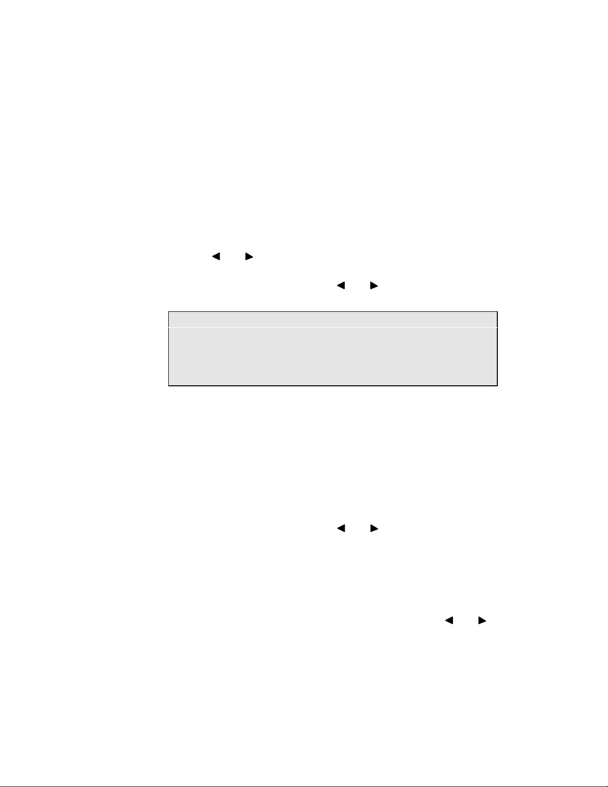
• When the
FIELD
key is pressed while at the first field of a menu, the previous
menu will be displayed and the data that was displayed will be entered (within the
permitted range). Similarly, pressing the
FIELD
key at the last field will
display the next menu.
NOTE: The range of numerical values are listed under the Technical
Specifications (and in the figures that describe RS232 Commands in
Section 7), and you cannot input data that exceeds the maximum of the
range given. If you do key-in a larger (or smaller) number, the largest
(or smallest) allowable value will be entered.
1.2 EVENTS AND METER KEYS AND DISPLAY
The EVENTS and METER keys in the DISPLAY area on the front panel are used to select test
results and measured data. Sub-sections 1.2.1 through 1.2.4 describe the kinds of data
provided by pressing these keys (the [SHIFT] key must first be pressed so that its green LED is
lighted):
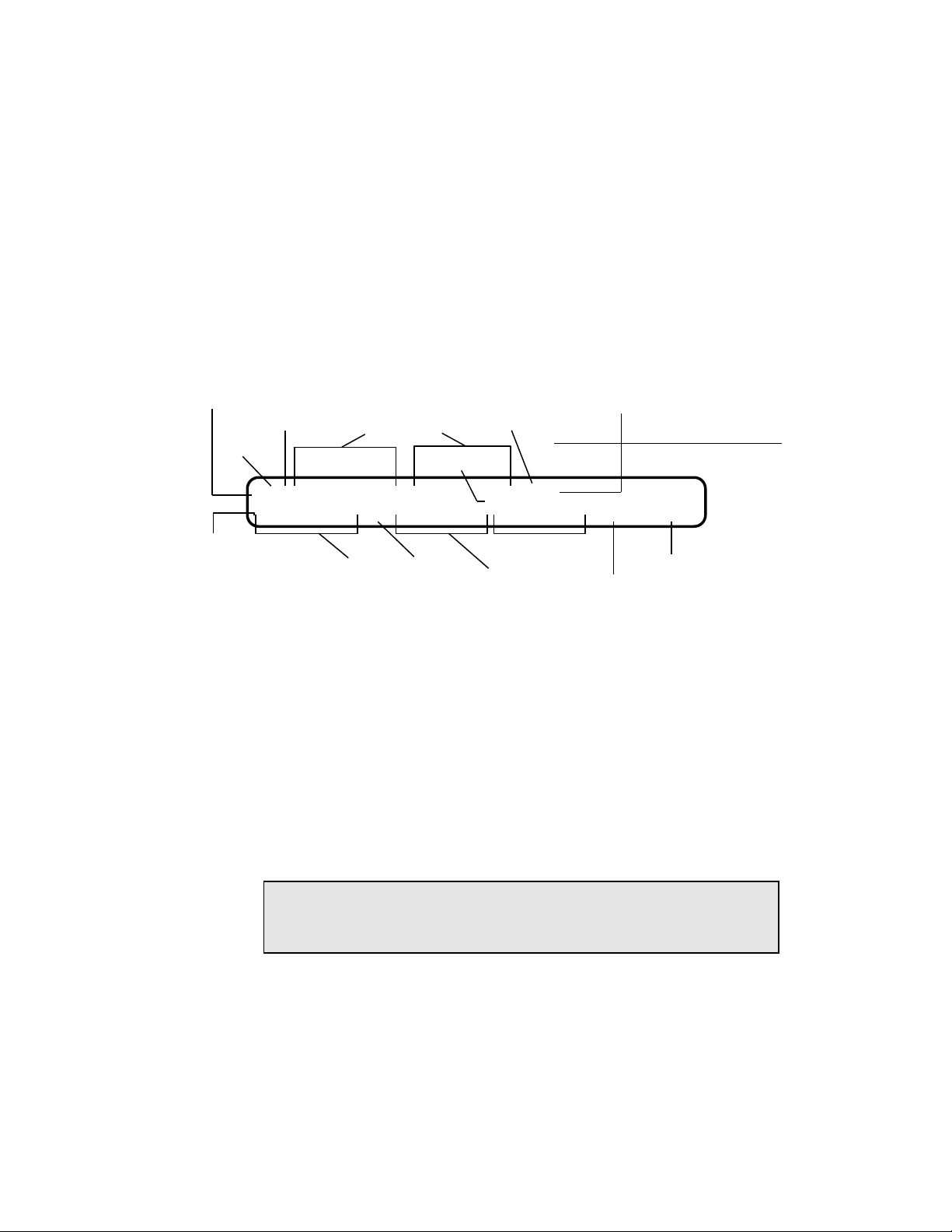
1.2.1 EVENTS ([SHIFT][1]) Key: This causes the Call Event characters to appear on the first
line of the display (Figure 1-2). The EVENTS LED will also begin flashing (unless
FREEZE has been activated - see 1.5.1). Up to 40 characters may be displayed at one
time, but the display may be scrolled with the
characters.
FIELD
keys to display a total of 80
A flashing digit or event indicates that the event was generated from the Analog Switch
("far end" for PCM). A steady-state display indicates that the event was generated
from the analog Te/Line ("near end" for PCM); see note under 1.2.2 for exceptions.
The second line of the Events Display gives a complete analysis of an event. Position
the cursor on whatever character of the first line you choose by using the
FIELD
keys. The second line of the display immediately indicates the available data for that
event.
0037-S01.L_19 February 10, 2000
1-3
Page 21
Front Panel Operation (18-0037) AM8a Instruction Manual
This character signifies a new call:
Wink
Off Hook
Dialed Digits
On Hook
Cursor
Decoded signaling
Steady
Character
Flashing
Character
Analog Terminal/Line
(PCM near end) signaling
Analog Switch
(PCM far end) signaling
>HW2125551212W8189155441Hhh
00:02.163 T5 -06/0770 -06/1336 0059/0060
Digit Analysis
(Digit selected from
1st line by using
underline bar cursor)
NOTE: A flashing field in the 2nd line indicates a value that is outside of the
range specified by the ANALYZE parameter
Elapsed
Time from
Off Hook
DTMF
Digit
5
Low-Band
Level/Frequency
High-Band
Level/Frequency
Tone Duration
Off-Time
Figure 1-2. AM8a Events Display
1.2.2 Events Display Character Set: A list of the possible characters which may be displayed
on the Events Display follows. Following each description is a sample of what the
second line of the display would show if the character were selected for analysis.
• Upper-case characters represent the beginning of an event.
• Lower-case characters represent the end of an event.
• Flashing characters indicate the event originated from the switching (far end)
equipment.
• Non-flashing characters indicate the event originated from the Te/Line (near end)
equipment.
NOTE: Some non-flashing events such as Tones on a 2-wire circuit may have
originated from either the switch or the Term/line equipment. The
direction of these events cannot be determined.
> indicates the beginning of a new call sequence. ">" will appear only at the first
position if the CONFIG DISPLAY:MODE parameter is set for "new call reset". More
than one new call sequence (with its beginning ">" in some other position) is only
possible if the DISPLAY:MODE parameter is set for "manual reset" or "scroll". The
time and date of the event and setting from MODE:MODE parameter is shown on
the second line when this character is selected.
15:00:15 02-28-92 Emulate (or Monitor) Switch (or Term/Line)
February 10, 2000 0037-S01.L_
1-4
Page 22

AM8a Instruction Manual (18-0037) Front Panel Operation
0-9 dialed digits. (*, #, and A, B, C, or D may also be dialed digits; see 1.2.3.)
? means that the AM8a detected a dual-frequency tone that did not meet the
specifications to be either a Tone Dial Digit or a Call Progress Tone. These occur
mostly on a voice line which has speech on it. Set the DIG DET parameter (see
2.5.2) to "narrow" or "limit" to eliminate the "?"s.
If DIG DET is set to "wide", increasing the GUARD time parameter in the ANALYZE
setup (see 4.10.2) may help to reduce the number of "?"s encountered. Invalid
events may also be dial pulses if there are more than 15 pulses.
00.05.847 T? -18/1161 -11/1646 1637/0025
00:07.247 P? 09.9 pps 52% 768 ms
NOTE: For SLC-96 II (Mode II) events, LDS means "Local Digital Switch",
and "RT" means Remote Terminal. For more information refer to 2.3.2,
2.5.3 and 2.5.4.
a is SLC®96 II Activity RT to LDS
b is SLC®96 II Activity Update RT to LDS
c is SLC®96 II Looping Test
d is SLC®96 II Assignment Update Request RT to LDS
e is SLC®96 II Idle/Trunk De-assignment update (E & M circuit)
f is SLC®96 II No Alarm RT to LDS
F indicates the AM8a received a hook flash.
00:03.215 Flash 489ms
H will appear when an "OFF HOOK" (seizure) has been detected. When "H" appears
as the first event, it signifies the beginning of that call sequence. All events which
follow will have an occurrence time relative to the "H". An "H" which occurs
later in the call sequence indicates a distant "OFF HOOK" (answer supervision).
00:00.000 Off Hook
h indicates the detection of an "ON HOOK".
00:01.385 On Hook
i is SLC®96 II Trunk Assignment LDS to RT
j is SLC®96 II Assignment Update LDS to RT
0037-S01.L_19 February 10, 2000
1-5
Page 23

Front Panel Operation (18-0037) AM8a Instruction Manual
k is SLC®96 II Looping Test
l is SLC®96 II Activity Update Request LDS to RT
m is SLC®96 II Idle/Trunk De-assignment update (E & M circuit)
n is SLC®96 II COT Trunk De-assignment
P indicates the detection of reverse polarity on the line pair. This is used on Loop
circuits to indicate answer supervision. It will also indicate the detection of a
Delay START SIGNAL if EXPECTED or a Wink if the Wink duration exceeds
999ms.
00:01.325 Supervision Begin
p appears after the polarity reversal has been removed. The analysis line will
display the time answer supervision was removed.
00:05.398 Supervision End
R appears when ringing is detected.
00:03.332 Ring Begin 101.2 v 20.5 Hz
r will appear when the ring voltage is removed.
00.05.430 Ring End
T appears when the AM8a detects a single tone.
00:10.209 Tone Begin
t will appear when the single tone is removed.
00:25.998 Tone End -13dBm 1004Hz
W will appear when a "WINK" is detected or generated.
00:00.355 Wink 250ms
X indicates the beginning of a Call Progress Tone. A call progress tone consists of a
dual tone detected which does not meet the frequency requirements of tone
dialing. This includes Dialtone, Line busy, Reorder, and Ringback.
00:00.285 Call Progress Begin
00:00.316 Dial Tone Begin
February 10, 2000 0037-S01.L_
1-6
Page 24

AM8a Instruction Manual (18-0037) Front Panel Operation
x signifies the end of the call progress tone. Selecting this for analysis will display
the Level and Frequency for each of the tones.
00:00.756 CP End -17/480 -16/620
00:00.501 DT End -13/350 -13/440
y is SLC®96 II Trunk De-assignment LDS to RT.
1.2.3 Dialed Digits (O - 9, *, #, A, B, C, D): Digits appear whenever a valid dialed digit is
detected. A digit is considered valid if it meets the following criteria:
• The level of a tone dial digit exceeds the Threshold programmed in the ANALYSIS
Setup menu.
• The Low and High band frequency components must be within + 3.5 % of the
nominal frequency for Tone Dial digits.
• The Speed is between 5 and 25pps and the % Break is between 40 and 85 % for
Pulse dialing.
• A KP digit must be received before any other MF digit will be analyzed.
• An ST, ST3P, STP, or STP2 digit (ST, A, B, or C key) must be received to end the
MF digit analysis.
The following are examples of digit events and details:
EVENT DETAIL
5 00:13.385 T5 -06/770 -06/1336 0059/0060 DTMF
1 00:05.325 M1 -07/700 -07/900 0070/0071 MF(R1)
2 00:04.603 P2 09.9pps 56% 699ms Pulse
NOTE: MF(R1) digits will not be seen if DIALTONE is used as a Start Signal.
1.2.4 METER ([SHIFT][2]) Key: When the METER key is pressed, measurements and test
statistics are available for voltage, current and PCM evaluations, including phase
relationships between two T-1 spans. Use the MENU and VALUE keys to select the
Meter mode. Section 6 describes the meter functions.
0037-S01.L_19 February 10, 2000
1-7
Page 25

Front Panel Operation (18-0037) AM8a Instruction Manual
1.3 SETUP AREA
The Setup area on the front panel controls the programming of the AM8a unit for all test
procedures. It is here that required parameters are set for configuration, emulation, analysis
and auto dialing functions. Each of these areas are briefly described below, and specific
information on all the parameters that are available in each Setup category is shown in Section
2, 3, 4, and 5.
1.3.1 CONFIG'N ([SHIFT][5]) Key: When selected, the menus identified by "CONFIG" are
presented. All the parameters for basic configuring of the line can be set in this mode
(software version is also shown). Settings include:
• Whether the AM8a is to be used as a switch (CO) or terminal/line.
• Which trunk type is being monitored or emulated.
• Time and date.
• RS232 baud rate, parity, and CR delay.
• Flags for SLC®96 display options.
• Manual or new-call display reset.
1.3.2 EMULATE ([SHIFT][6]) Key: When selected, the menus identified by "EMULATE" are
presented. This mode allows access to parameters that control timing of AM8a
generated events. Settings for voltage, frequency and timing are to be made here, as
well as for impedance, ringing voltage, dial tone and dial pulse, recall (flash and
unbalance), and tone dialing.
1.3.3 ANALYZE ([SHIFT][7]) Key: When selected, the menus identified by "ANALYZE" are
selected. These parameters are used to instruct the AM8a on how to interpret events
the events it encounters. It is also used to set thresholds for flagging and printing
errors or flaws in a call sequence.
1.3.4 AUTO DIAL ([SHIFT][8]) Key: When selected, the dialed number display is presented.
Stored dialing sequences which can be automatically recalled are set in this display.
Up to 11 dialed sequences can be stored in Auto Dial. Each sequence can contain up to
60 characters. This display is shown in Section 5.
February 10, 2000 0037-S01.L_
1-8
Page 26
AM8a Instruction Manual (18-0037) Front Panel Operation
1.4 CONTROL ON/OFF KEYS
Additional control of configuration on the AM8a is available through ON/OFF function keys
on the lower left of the front panel. (See Figure 1-1.) The green LED indicates when the
function is ON. The following descriptions review the specific configuration control
provided:
1.4.1 INPUT ([SHIFT][*, KP]) Key: This key controls the AM8a connection to the selected line
being emulated or monitored. Connections are described in Section 6 along with
metering of circuits.
• ON: the test set has full access to the lines selected; this is the standard condition.
• OFF: all AM8a interfaces to the line jacks change to high impedance or open
circuits that will not interfere with the line under test.
NOTE: The OFF position is a built-in safety feature that prevents glitches during
any rearrangement of the external connections during AM8a configuration
changes. In addition, if certain trunk configuration parameters are
changed, INPUT is forced OFF.
1.4.2 TIMS ([SHIFT][#, ST]) Key: This key controls connection of a Transmission Impairment
Measurement Set (a TIMS such as the Ameritec AM5XT) to test the transmission
quality of the line. The TIMS is connected to the TIMS jacks on the front panel. The
key provides a three-position toggle.
NOTE: For PCM1 or PCM2, the TIMS jacks are connected internally to the selected
CHANnel. Refer to the Appendix that describes PCM operation.
• 1 (green LED ON): When on, the TX and RX circuitry in the AM8a is connected to
the TIMS 2W/TX and RX jacks. For 2W circuits or analog LOOP, the TIMS 2W/TX
jack is used. For 4W circuits, both jacks are used.
• 2 (green LED flashes): When in a monitor PCM mode, the TIMS jack RX and
TX/2W connections to the AM8a circuitry are reversed.
• 3 (green LED OFF): The TIMS jacks are Open and there is no connection to the
AM8a circuitry.
0037-S01.L_19 February 10, 2000
1-9
Page 27

Front Panel Operation (18-0037) AM8a Instruction Manual
1.4.3 TALK ([SHIFT][
VALUE
) Key: This control allows the operator to talk over the circuit
under test.
• ON: Enables the speakerphone function of the unit, using the front-panel
microphone and speaker. If a handset is connected, the front panel microphone
and speaker are disabled, and the handset functions as a telephone. To avoid noise
and false events, ON should not be enabled until the voice connection is made.
• OFF: Speakerphone (or handset) is inoperative.
1.4.4 AUTO ([SHIFT][
VALUE
) Key: This control applies only when the AM8a is used in
emulation. It is not used when set to Monitor.
• ON: If EMULATE has been activated, pressing "SEIZE" key will cause the AM8a to
go Off Hook, and emulate the functions associated with the Calling Party (i.e.
detect the expected start dial signal and outpulse AUTO DIAL numbers) of the Trunk
Type programmed in the CONFIG'N Setup menu.
The AM8a will perform the functions associated with switching equipment of the
selected Trunk Type when an incoming seizure is detected. (i.e. provide
programmed start dial signal).
• OFF: The AM8a generates individual emulation events only in response to manual
input.
1.5 MENU/DATA CONTROL KEYS
1.5.1 FREEZE ([SHIFT][B]) Key: Freeze allows the user to Freeze the Events Display to halt
the display update as new events are encountered. FREEZE is most useful in viewing
specific events embedded within a long call sequence.
• ON: Events Display will indicate a "," to alert the user that a FREEZE has occurred.
In addition, the green LED for DISPLAY EVENTS (over [1] key) will go on steady.
• OFF: To disable the Freeze, use the CANCEL key. The green LED above EVENTS
will resume flashing, and the Events Display will be updated as new events arrive.
February 10, 2000 0037-S01.L_
1-10
Page 28

AM8a Instruction Manual (18-0037) Front Panel Operation
1.5.2 PRINT ([SHIFT][C]) Key: The PRINT key allows the user to obtain a RS232 report for a
selected section or display. The PRINT key can be used to print two types of reports,
"Short Print" and "Long Print". For examples, refer to Section 7.
• Short Print: Press [SHIFT] then [PRINT] for a Short Print. The Short Print will
provide a printout of the selected display event or Setup parameters. The printout
will consist of only the Events or the selected Setup.
• Long Print: Press [SHIFT] then [PRINT] and HOLD PRINT for longer than two (2)
seconds. The Long Print will provide a printout of the selected Display or Setup
section. The printout will consist of both Events AND Details, or ALL Setup
parameters.
1.5.3 CANCEL [SHIFT][D] Key: The CANCEL key is to disable the FREEZE of the Display. It
is also used to clear the display of past Events when desired. While in the Meter
Display, use the CANCEL to zero the PCM counters and to align the FRAME SYNC
display. In PCM Monitor mode with random channel select, this key will abort the
currently-selected channel so that another channel can be monitored.
1.6 SIGNALING KEYS
The signaling keys are used to initiate a call event when Emulate mode has been selected by
configuration parameter "MODE: MODE emulate"(2.1).
If the AM8a has been placed in the AUTO mode, the AM8a will perform some functions
automatically, as appropriate to its "MODE: IMITATE" "switch" or "te/line" setting, when it
receives signals from the circuit under test.
If the AM8a is not in AUTO mode, the appropriate key must be pressed when the operator sees
the incoming event displayed.
1.6.1 SEIZE Key: This key alternately puts the line being emulated in an Off-Hook or
On-Hook condition.
0037-S01.L_19 February 10, 2000
1-11
Page 29

Front Panel Operation (18-0037) AM8a Instruction Manual
1.6.2 START Key: This key transmits the "Start" signal according to the "Start Signal"
parameter that has been defined by the "DIALING: START SIGNAL" EMULATE parameter.
• For "dial tone", another press of the key will remove it.
• For "delay" start signal (similar to "wink"), another press before it's programmed
end time (START TIME: DLY: /ENDms) will terminate it.
• For "wink", each press will send a "wink" of the programmed duration (WINK:
/DURms).
• For "immediate" dial, it has no function for a Te/Line that is set for analog (loop)
operation.
1.6.3 RING Key: This key sends ringing to alert the terminal equipment that a call is coming
from the AM8a. Ringing will be applied according to the "RINGING:" parameters given
in the EMULATE Setup. Pressing the RING key again will remove the ringing signal.
CAUTION: Placing an excessive (>5 REN) Load across Tip Ring during Ring
application may cause the AM8a to reset. Ringing will not be
generated if any of the following conditions exist:
1. Low battery indication on display.
2. Loop is seized ( i.e. Off Hook).
3. If > 14mA ring trip current is detected.
4. An excessive ringer load exists for several minutes.
5. Unit is emulating a TE/LINE in analog loop mode.
1.6.4 REV Key: This key controls battery polarity for the line under test when emulating a
Switch. Each press changes the polarity on the line. This key is equivalent to the
SEIZE key when Emulating TE/LINE equipment.
1.6.5 SEND TONE ([SHIFT][RING]) key: This is a secondary function of the RING key. Press
[SHIFT] then [RING] and the AM8a will send a single tone at the Level and Frequency
programmed in the EMULATE "SEND TONE:" setup parameters.
February 10, 2000 0037-S01.L_
1-12
Page 30

AM8a Instruction Manual (18-0037) Front Panel Operation
1.7 DATA ENTRY KEYS FOR SIGNALING
In addition to numerical SETUP parameter values (and the SHIFT functions printed above some
of them in green), the two rows of Data Entry keys provide all 16 DTMF (Dual Tone
Multifrequency) digits for signaling, all 15 MF digits, and all 10 dial pulse digits.
Keys 1-7 also activate dialing sequence signaling functions printed in red beneath them (after
SHIFT has been pressed twice so its red LED is on). These additional signaling functions
include:
1.7.1 WAIT DT ([SHIFT][SHIFT][1]) Key: This key causes the AM8a to stop dialing and wait
for Dial Tone before continuing. "P" will appear where this is entered into an AUTO
DIAL location.
1.7.2 WAIT WINK ([SHIFT][SHIFT][2]) Key: This key causes the AM8a to stop dialing and wait
for a valid wink before continuing. "W" will appear where this is entered into an AUTO
DIAL location.
1.7.3 WAIT ([SHIFT][SHIFT][3]) Key: This key gives a fixed wait of 3 seconds in dialing. "-"
will appear where this is entered into an AUTO DIAL location.
1.7.4 FLASH ([SHIFT][SHIFT][4]) Key: This key gives a momentary On-Hook state, with
duration determined by the "FLASH" parameter entered in ANALYZE. "F" will appear
where this is entered into an AUTO DIAL location.
1.7.5 UNBALANCE [SHIFT][SHIFT][5] Key: With this key, a momentary unbalanced condition
(resistance on the conductors unequal with respect to ground) is applied to the line for
a duration specified under ANALYZE. "U" will appear where this is entered into an
AUTO DIAL location.
1.7.6 TOGGLE DIAL ([SHIFT][SHIFT][6]) Key: If different dialing types are to be used in the
same call, this key offers a method of selecting the changes. Each time a Toggle Dial
is encountered, it changes dialing modes. The sequence is: TT, DP, MF, in rotation.
"T" will appear where this is entered into an AUTO DIAL location.
1.7.7 BLANK ([SHIFT][SHIFT][7] Key: Inserting a blank into an AUTO DIAL number will stop
the dialing sequence at that point.
0037-S01.L_19 February 10, 2000
1-13
Page 31
Front Panel Operation (18-0037) AM8a Instruction Manual
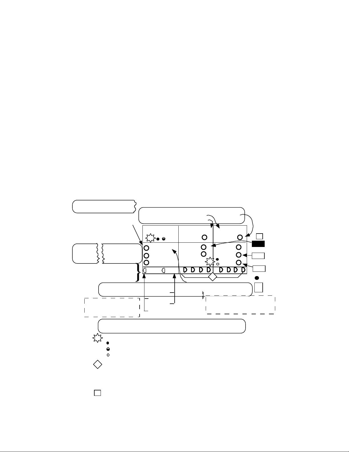
1.8 SIGNALING STATUS LEDs
The Signaling Status LEDs show the TRUNK TYPE that the AM8a is IMITATING and whether it
is operating as an analog terminal/line or switch, or as a PCM terminal. Figure 1-3 shows
these indicators and identifies the menu parameters which set up the operation (see Section 2
sub-sections for appearance of menus and more information on the parameter selections). For
more information on the signaling keys shown in the figure, refer to 1.6.
TRUNK :
CONFIG :
(see 2.4)
CIRCUIT
CONFIG:
(see 2.2.2)
TRUNK TYPE
E & M 4W
E & M 2W
ANALOG/PCM
pcm int clk
pcm loop clk
(see 2.3.1
- 2.3.4)
PCM
CONFIG 1:
PCM selections have no
effect on operation if
CIRCUIT is analog
PCM
CONFIG 2:
panel legends for LEDs
a, b, c, d LEDs indicate signaling bits for the PCM CHANnel
L
selected. They will scroll if there is no frame sync (see Section 6, subsections 6.9 and 6.10 for meter display of frame sync and bits). When
frame sync is established, bits will be lit in patterns to indicate
CHANnel conditions.
Typical switch actions resulting in LED indication as condition is
s
detected. See sub-section 1.6 for more information.
DID
SF
loop
ground
analog
(see 2.3.5)
= lit
= flashing
= not lit
LEDs indicate unit configuration based on menus
E
MODE
emulate
monitor
SWITCH
EMULATEEMULATE
T-GND
RINGING
T+R–
T–R+
a b c
M
d
MODE
CONFIG:
TRUNK /SLC
TYPE
/
E&M/SLC
LOOP/DID
GND ST/SF
PCM2 PCM1
(see 2.1)
®
®
IMITATE
Switch
Te/Line
TERMINAL/LINE
OFFHOOK
R-GND
a b c d
L
INPUT
pcm 1 on
pcm2 on
rpt 1 to 2
rpt 2 to 1
FRAMING
SLC
®96 I
{
SLC
®96 II
D3/D4
ESF
ZERO SUP
AMI
CHAN
1
When SLC®96 I or II is selected,
E&M/SLC indicator will flash.
MODE must be monitor.
OFF HK a/b ON HK a/b
auto
0/0
.
.
.
X/1
auto
0/0
.
.
.
X/1
Figure 1-3. Signaling Status LEDs
s
SEIZE
RING
REV
*
KP
INPUT
February 10, 2000 0037-S01.L_
1-14
Page 32
AM8a Instruction Manual (18-0037) Front Panel Operation
1.9 STORE SETUP
The STORE function will save up to 20 different Configuration setups and up to 20 different
Emulate/Analyze parameter sets. To store parameters in either SETUP category, press [SHIFT]
then [STORE], followed by the appropriate number as indicated in the following sequence:
NOTE: The STORE function will NOT operate while the AM8a is set to the EVENTS
Display or is displaying the DATE/TIME. Current parameters for
EMULATE/ANALYZE will be stored if their locations are specified, even if the
CONFIG'N SETUP mode is selected (and vice verse).
1. Press [SHIFT] (so its green LED is on) then [STORE][n][n].
nn = 00 - 19 for CONFIG
20 - 39 for EMULATE/ANALYZE
2. After the storage location has been input, one of the following displays will
appear with instructions for the next actions.
STORE TRUNK CONFIGURATION ?
PRESS "MENU UP" (YES), OTHER KEYS (NO)
STORE EMULATE/ANALYZE ?
PRESS "MENU UP" (YES), OTHER KEYS (NO)
;; CAN NOT STORE, SETUP PROTECTED
PRESS ANY KEY TO CONTINUE
Pressing Menu up will store the current
Config setup, any other key will abort
the store sequence.
Pressing Menu up will store the current
Emulate/Analysis setup, any other key
will abort the store sequence.
This display will appear if the setup is
protected. If storage is still desired, go
to the Config Setup menu and disable
the memory protect. Then repeat the
Store sequence. Be sure to enable the
memory protect upon completion of the
storage.
NOTE: Some Configuration parameters are not are included in a stored
Configuration. They are: Protect/Unprotect, Baud Rate, Parity,
Date/Time, Password, and Display Mode. Since they are not stored, they
also cannot be recalled; values that appear on power up are whatever were
last set.
0037-S01.L_19 February 10, 2000
1-15
Page 33
Front Panel Operation (18-0037) AM8a Instruction Manual
1.10 RECALL SETUPS
RECALL is used to recall stored Configuration, Emulate, and Analysis parameters when in a
Setup mode. It may also be used to recall pre-stored "Auto Dial" numbers when Emulating
Term/Line equipment while in the Events Display mode.
1.10.1 RECALL Setup Parameters:
1. Select one of the Setup modes. (CONFIG'N, EMULATE, or ANALYZE, but not AUTO
DIAL.
2. Press [SHIFT] then [RECALL] then [n][n].
nn = 00 -19 for CONFIG'N
20 - 39 for EMULATE/ANALYZE
single [*] to recall ALL parameters before last power-off.
3. The AM8a will recall the setup based on the previously stored parameters for the
selected location.
1.10.2 RECALL Auto Dial Sequence:
NOTE: The AM8a must be Configured so that it is expected to dial (i.e: Emulate
Te/Line, and Off Hook).
1. Select EVENTS Display.
2. Press [SHIFT] then [RECALL] then [Auto Dial location (0 - 9)] or ["*"] for Last
Number Dialed.
NOTE: Last Number Dialed accumulates all out-pulsed digits from "Off- Hook" to
"On-Hook" for each call sequence.
1.11 SPEAKERPHONE/AUDIO MONITOR
The speakerphone is located on the front panel, labeled TALK. The VOLUME control adjusts to
the level of the speaker. A handset must be plugged into the modular jack labeled HANDSET.
The TALK (ON/OFF) key LED must be lighted.
1.11.1 Speakerphone in talk mode: To use the speakerphone the AM8a must be in
Emulation mode, because the Talk Mode is used to communicate with the person at
the other end of the line. In effect, this uses the AM8a as a speakerphone itself.
February 10, 2000 0037-S01.L_
1-16
Page 34

AM8a Instruction Manual (18-0037) Front Panel Operation
Anything spoken into the microphone will go out on the line, and anything coming in
will go to the speaker. To avoid unwanted noise events, do not go into the Talk
Mode until the called number has answered.
1.11.2 Handset: If you plug in the handset, the unit automatically detects it, activates the
handset circuits, and the microphone and speaker are deactivated. All other
conditions for speakerphone apply to handset.
NOTE: Refer to Figure 1-1 for Handset connections.
1.11.3 Audio Monitoring: When numbers are dialed the speakerphone will monitor dial
tones, dial digits, and tones from the switch or line. The VOLUME control adjusts the
monitor level.
0037-S01.L_19 February 10, 2000
1-17
Page 35

Front Panel Operation (18-0037) AM8a Instruction Manual
February 10, 2000 0037-S01.L_
1-18
Page 36

AM8a Instruction Manual (18-0037) Configuration Parameters
2. CONFIGURATION PARAMETERS
The following displays show in sequence the types of configuration parameters used to
program the AM8a. To use these menus press the CONFIG'N key.
2.1 MODE CONFIG
MODE :
CONFIG:
Alternate:
2.1.1 IMITATE: The AM8a can operate as either terminal/line equipment or as switching
(CO) equipment.
te/line: The AM8a will perform the functions associated with the terminal or line
equipment of the circuit under test. (i.e. seizure, dial out, ring trip, etc.)
switch: The AM8a will provide the functions associated with the switching equipment
of the circuit under test. (i.e. battery, start dial signal, ringing, etc.)
2.1.2 MODE: The MODE selects whether the AM8a will emulate or monitor the equipment as
selected by the IMITATE parameter.
monitor: The AM8a is non-intrusive to the circuit. Events will be displayed as they
occur and the statistics will be recorded for analysis. Call progress tones and dialing
will be displayed as they appear.
emulate: The AM8a will provide the signaling IMITATE mode selected. The signals
provided are specified by the parameters in the EMULATE menus.
NOTE: Emulate cannot be used with SLC®96 I or SLC®96 II INPUT (see 2.3.1).
IMITATE
switch
te/line
MODE
monitor
emulate
0037-S02.L_22 February 10, 2000
2-1
Page 37

Configuration Parameters (18-0037) AM8a Instruction Manual
2.2 CIRCUIT CONFIG
The Circuit Config menu allows the user to specify the characteristics of the trunk type to be
tested.
CIRCUIT:
CONFIG :
Alternate:
ANALOG IMPEDANCE
900 ohm
135 ohm
600 ohm
ANALOG/PCM
pcm loop clk
analog
pcm int clk
1200 ohm
2.2.1 ANALOG IMPEDANCE: This parameter selects the termination used when connected to
an analog loop line.
2.2.2 ANALOG/PCM: This parameter allows the selection of direct analog operation or PCM
operation. (PCM will function on each voice channel according to the selections made
in the TRUNK CONFIG menus.
analog: Selects the analog input jack (LOOP T/R) for connection to the circuit.
pcm int clk: (Internal Clock) the AM8a will generate the clock for PCM framing
information. In this case, the AM8a acts as a "Master" via the PCM1 or PCM2 TX jack.
pcm loop clk: (External Clock) uses the PCM signal it receives to obtain framing data.
In this mode, the AM8a acts as a "Slave" via the PCM1 or PCM2 RX jack. For testing in
repeat (drop and insert) mode the PCM signal with the clock (framing data) must be
connected to the PCM1 RX jack. (Refer to 2.3.3).
February 10, 2000 0037-S02.L_
2-2
Page 38

AM8a Instruction Manual (18-0037) Configuration Parameters
2.3 PCM CONFIG 1 and PCM CONFIG 2
The PCM CONFIG 1 menu allows the user to select the PCM input, framing, zero substitution
code word, and time slot or channel for voice measurements.
PCM :
CONFIG 1:
Alternate:
The PCM CONFIG 2 menu selects the a and b bit coding for off-hook and on-hook conditions.
Refer to Section 6.10 for description of the Meter display of these bits.
PCM :
CONFIG 2:
Alternate:
INPUT
pcm 1 on
pcm 2 on
rpt1 to 2
rpt2 to 1
OFF HK a/b
FRAMING
D3/D4
ESF
SLC 96 I
SLC 96 II
auto
0/0
0/1
1/0
1/1
0/X
1/X
X/0
X/1
ZERO SUP
AMI
B8ZS
ZCS
ON HK a/b
auto
0/0
0/1
1/0
1/1
0/X
1/X
X/0
X/1
CHAN
1
0, 1 to 24
or
–1 to –96, –97
2.3.1 INPUT: This parameter selects how the input jacks will be used to interface with the
PCM link.
pcm1 on: selects the PCM1 jacks for emulate or monitor connection.
pcm2 on: selects the PCM2 jacks for emulate or monitor connection.
rpt 1 to 2: is used during Drop & Insert testing. This mode allow the selected CHANnel
to be used for emulation towards the equipment connected to the PCM1 input jacks;
other channels are uninterrupted to PCM2.
0037-S02.L_22 February 10, 2000
2-3
Page 39
Configuration Parameters (18-0037) AM8a Instruction Manual
rpt 2 to 1: is used during Drop & Insert testing. This mode will allow the selected
CHANnel to be used for emulation towards the equipment connected to the PCM2 input
jacks; other channels are uninterrupted to PCM1.
NOTE: In MONITOR mode all channels pass from PCM1 to PCM2 when rpt 1 to 2 or
rpt 2 to 1 are selected. See Section 6 for metering the a and b bits to find an
idle channel that can be selected for drop and insert testing.
In Drop & Insert testing, the equipment which supplies the "Master" clock
for framing must be connected to the PCM1 input jack.
2.3.2 FRAMING: This parameter selects the span framing type assignment that the AM8a can
emulate and monitor.
D3/D4: is the most popular type of framing. It uses 12 separate frames in a super-
frame. The signaling bits are identified as "a" and "b" bits.
ESF: Extended SuperFrame is another popular type of framing. This type uses 24
frames rather than 12 frames. Its signaling bits are" a, b, c, and d".
SLC®96 I: (SLC® 96 Mode I) monitors 96 channels or data link on four spans (A, B, C,
and D). Assignment of channels to time-slots is fixed. Refer to Table 6-5 for these
assignments.
SLC®96 II: (SLC®96 Mode II) monitors 96 channels or data link on two spans (A and C).
Assignment of channels to time-slots is on as-available basis. Refer to 2.5.4 for use of
activity message to determine line groups and active channels.
NOTE: SLC®96 I and SLC®96 II can only be used in monitor mode.
2.3.3 ZERO SUP: Zero Suppression is the way that the AM8a handles a data pattern of all
"0's" during transmission.
AMI: (Alternate Mark Inversion) is the standard protocol for T1 spans. AMI does not
supply any zero suppression conversions.
B8ZS: (Binary Eight Zero Suppression) will insert two bipolar violations when eight
consecutive zeros are encountered. The receiving equipment will recognize this and
remove the BPV's and correctly interpret the data.
February 10, 2000 0037-S02.L_
2-4
Page 40

AM8a Instruction Manual (18-0037) Configuration Parameters
ZCS: (Zero Code Suppression) will insert a "1" bit to prevent the transmission of eight
or more consecutive "0" bits.
2.3.4 CHAN: This parameter is used to select either a PCM time-slot or voice channel. A
channel is not passed through when the AM8a is in drop and insert input and emulation
mode. Selection options are:
0: Random selection of first time-slot that goes active (monitor only).
1 through 24: T1 time-slot to monitor, emulate, or drop and insert. SLC®96 I time
slot to monitor. (See Figure 6-5 for time slot to channel assignment
at SLC®96 equipment shelves).
–1 through –96: SLC®96 I or II Voice channel to monitor.
–97: SLC®96 I or II Data link to monitor (see 2.5.3 and 2.5.4).
2.3.5 OFF HK a/b or ON HK a/b: These parameters set the a and b bit patterns that will be
generated or detected as off-hook or on-hook.
AUTO: The bit patterns are set in accordance with the TRUNK TYPE or the SLC® TYPE.
Refer to 2.4.1 and 2.4.2
0/0 through X/1: defines bit patterns for specialized signaling used in some equipment
that may be tested.
2.4 TRUNK CONFIG
This menu selects the trunk type that is emulated or monitored. It also sets the type of voice
channel that is monitored if the framing (see 2.3.2) has been set for SLC®96 I or SLC®96 II.
Finally it sets the E & M type if E & M 2W or E & M 4W have been selected as TRUNK TYPE.
TRUNK :
CONFIG :
Alternate:
TRUNK TYPE
E & M 4W
E & M 2W
DID
SF
loop
SLC®TYPE
SINGLE PARTY
UNIVERSAL V G
E & M TYPE
I
II
III
IV
V
ground
0037-S02.L_22 February 10, 2000
2-5
Page 41

Configuration Parameters (18-0037) AM8a Instruction Manual
2.4.1 TRUNK TYPE: The AM8a can be configured to interface with the types indicated by the
alternates shown in the menu. The types may be either direct analog or a voice channel
selected from a PCM link.
loop: This is the simplest type of interface. The terminal seizes a line by closing the
loop. If analog has been selected (see 2.2.2) the equipment is connected to the LOOP
T/R jack on the front panel. If PCM has been selected, the conditions are internally
emulated/monitored on a selected voice CHANnel.
ground: In ground start, the terminal seizes a line by grounding the tip lead. If analog
has been selected (see 2.2.2), the equipment is also connected to the LOOP T/R jack on
the front panel. If PCM has been selected, the conditions are internally
emulated/monitored on a selected voice CHANnel.
E & M 2W and E & M 4W: Refer to 2.4.3 for more information.
DID: This configuration is the same as LOOP except the switch initiates the seize and
dialing signals.
SF: This is a four-wire (TX and RX) configuration in which signaling and dialing is by
pulsed 2600 Hz tones.
2.4.2 SLC®TYPE: This selection is only active when FRAMING of SLC®96 I or SLC®96 II has
been selected (see 2.3.2) and is only for monitor mode.
SINGLE PARTY: must be used with TRUNK TYPE loop.
UNIVERSAL VOICE GRADE: can be loop or ground start.
2.4.3 E & M TYPE: This selection is only active when TRUNK TYPE of E & M 2W or E & M 4W
have been selected. The table below summarizes the connections that must be made to
the equipment for the TYPE parameters selected if in analog mode. For PCM modes,
the signaling bits will convey information:
E & M TRUNK INPUT E & M TYPE
Jack Signals
E te/line orig.
M switch orig.
SB signal battery
SG signal ground
TX
RX
February 10, 2000 0037-S02.L_
I
x
x
-
E & M 2W and 4W
E & M 4W
III
II
x
x
x
x
x
x
x
x
TRUNK TYPE
V
IV
x
x
x
x
-
x
-
x
2-6
Page 42
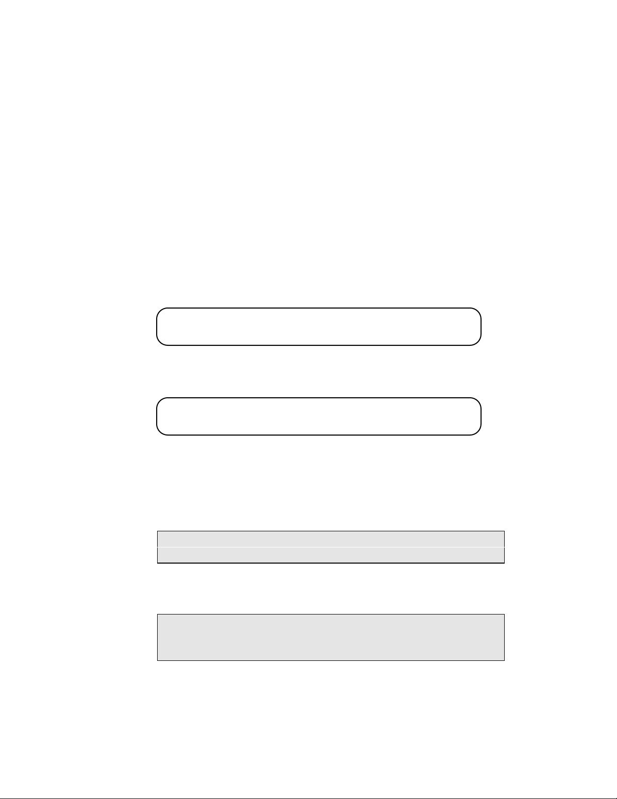
AM8a Instruction Manual (18-0037) Configuration Parameters
2.5 DISPLAY CONFIG 1 AND CONFIG 2
These menus control the AM8a LCD display and equivalent printouts. They allow the user to
set the display to respond to calls, dialing events, SLC® messages, and single-tone events.
DISPLAY:
CONFIG1 :
Alternate:
DISPLAY:
CONFIG2 :
Alternate:
2.5.1 MODE: This parameter controls how the events display will be updated.
new call reset: This selection will reset the display each time a new call is encountered.
Events will enter the display buffer until it is full (80 characters max). After it is full,
further events will be ignored until a new call is encountered.
NOTE: 40 characters will be displayed on the screen, while the remaining 40
characters are kept in the buffer until selected for viewing via the keys.
manual reset: This selection will display events until the 80 character buffer is full.
All events after this will be ignored until the display is cleared by pressing the [SHIFT]
[CANCEL] keys.
MODE
new call reset
manual reset
scroll
T/t MASK
DIG DET
narrow
wide
limit
NO
YES
0000000000 to
®
MSG
SLC
0000000001
1111111111
NOTE: In monitor mode for PCM, with channel number of 0 (random select)
specified, the [SHIFT][CANCEL] keys will immediately abort monitoring of
the current call so that the AM8a can monitor the next new call.
scroll: This selection will allow the most recent 80 events to be displayed as they
occur. Old events will scroll off the display and be discarded as new events replace
them. The FREEZE function is useful here to "stop" the display to analyze specific
events.
0037-S02.L_22 February 10, 2000
2-7
Page 43
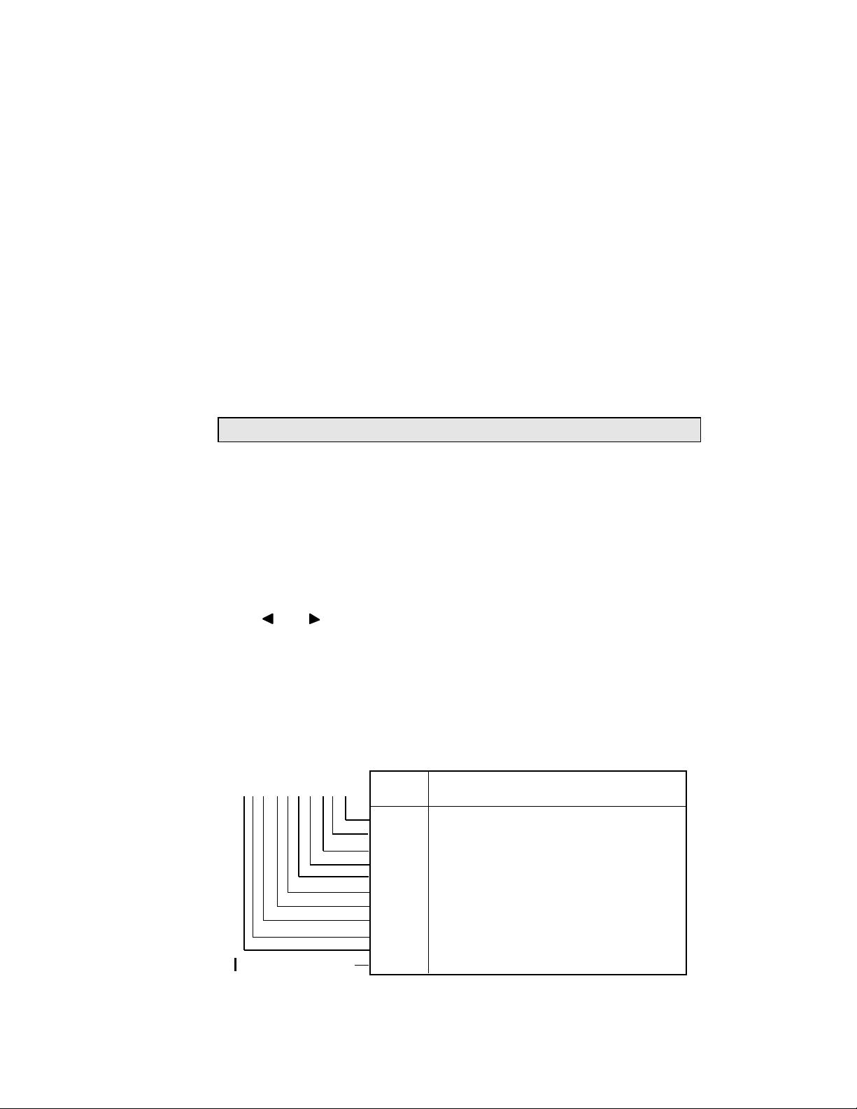
Configuration Parameters (18-0037) AM8a Instruction Manual
2.5.2 DIGit DETection: This selection defines the way in which the AM8a will display or
print dialed-digit events. These events may be pulse, DTMF, or MF(R1). Refer to
DIALING EMULATE: LOOP TYPE (¶3.3.1).
NOTE: MF(R1) digits will not be seen if DIALTONE is used as a Start Signal.
narrow: only dialed digits that are exceptions to the expected values, or are good will
result in a displayed/printed message.
wide: all dialed digits, including those that are unrecognizable, will result in a
displayed/printed message.
limit: only dialed digits that are good will result in a displayed/printed message.
2.5.3 SLC® MSG: This parameter allows the user to set a combination of 10 "flags" that
direct the unit to respond to various conditions in a monitored Mode II SLC®96 channel.
Use the
FIELD
keys to move to the flag. Use the 0 and 1 keys to set the flag.
When the flag is set to "1" the condition will result in a message. If set to "0", the
condition will be ignored.
The messages are identified by EVENT display codes (refer to 1.2.2) and DETAIL
messages; both are listed below (actual message text will vary to fit second line of
display):
x
=1 Message Detect active
x
SLC MSG
x x x x x x x x x x
no flag (always active)
=0 No Message Detect active
Event
Code
i
y
j
c or k
l
e or m
a
b
d
f
n
Trunk Assignment LDS to RT
Trunk De-assignment LDS to RT
Assignment Update LDS to RT
Looping Test
Activity Update Request LDS to RT
Idle/Trunk De-assignment update (E & M)
Activity RT to LDS
Activity Update RT to LDS
Assignment Update Request RT to LDS
No Alarm RT to LDS
COT Trunk Deassignment
Message
February 10, 2000 0037-S02.L_
2-8
Page 44

AM8a Instruction Manual (18-0037) Configuration Parameters
Line Group
27
29
31
33
35
25
a 01:50.588 RT Activity LG=n X X X X X X X X
b 01:50.588 RT Act Update LG=n X X X X X X X X
=1: Active Channel
=0: Inactive Channel
2.5.4 SLC® Activity Message: When the message detect active for the a or b events (shown
in ¶2.5.3) is set, the activity messages in the 4Kbps data link can be monitored when
CHANnel is set to -97 (refer to 2.3.4). The chart that follows decodes the messages to
identify the Line Group and the Active Channel(s) in the line group.
1
2
3
4
5
6
2.5.5 T/t Mask (single-tone event selection): This selection, on the second CONFIG menu
controls the display of single-tone events. When YES has been selected, all single-tone
events will be masked (not displayed). When NO has been selected, single tone events
are not masked (displayed).
13
15
17
19
21
23
37
39
41
43
45
47
2.6 RS232 CONFIG
This menu is used to configure the AM8a RS232 port. The settings can only be changed by
operator entry.
RS232 :
CONFIG:
Alternate:
BAUD RATE
9600
300
1200
2400
2.6.1 BAUD RATE: This selects the baud rate of the RS 232 port. Available baud rates are
shown by the alternates listed above.
2
4
6
8
10
12
26
28
30
32
34
36
14
16
18
20
22
24
PARITY
none
odd
even
38
40
42
44
46
48
3
5
7
9
11
1
CR DELAYsec
0
0 to 99 (1sec steps)
0037-S02.L_22 February 10, 2000
2-9
Page 45
Configuration Parameters (18-0037) AM8a Instruction Manual
CAUTION: When units are chained, set all parameters the same on each unit,
and do not exceed 2400 baud.
2.6.2 PARITY: This will select whether Even or Odd parity will be used for error checking.
This will also allow for NO parity check to be used.
2.6.3 CR DELAYsec: Carriage Return Delay. This parameter allows a delay to be inserted
after a carriage return is sent at the end of a line of text. This delay will prevent further
characters being sent during the time required for the carriage return in a printer
without a built-in buffer.
NOTE: The RS232 serial date will have the format of 1 stop bit and 7 data bits
when parity is enabled. When parity is disabled, 8 data bits will be used.
2.7 SECURITY CONFIG
The two security settings can only be changed by operator entry.
SECURITY:
CONFIG :
2.7.1 PASSWORD: is used for RS232 security. If PASSWORD is enabled ("yes"),
unauthorized access to the unit can be prevented. Access must be gained via a
"Logon" procedure. See the RS232 Entries and printouts in section 7 to set or change
passwords.
2.7.2 SETUP PROTECT: Setup allows the stored configuration to be protected from
accidental modification. When "yes" is selected and a STORE is attempted, the display
will indicate that Setup Protect is enabled; the STORE command will be ignored. To
STORE setups, set this parameter to "no".
NOTE: When Setup is PROTECTED, previously stored setups may be recalled as
normal. Also, parameters may be changed via the front panel controls or
RS232 commands.
February 10, 2000 0037-S02.L_
PASSWORD
no
yes
2-10
SETUP PROTECT
yes
noAlternate:
Page 46

AM8a Instruction Manual (18-0037) Configuration Parameters
2.8 PRINT CONFIG
This menu selects what information will be printed when the automatic print mode has been
enabled.
PRINT :
CONFIG:
Alternate:
AUTOPRINT
off
all calls,events only
all calls,events & details
flawed calls,events only
flawed calls,events & details
2.8.1 off: This selection AM8a will not automatically print the events and/or details that
have been analyzed.
2.8.2 all calls, events only: This selection will cause the AM8a to automatically print the
events it has analyzed. The printout will be output at the start of the next call
sequence. The printout will consist of the events of the call without any details.
2.8.3 all calls, events & details: This selection will cause the AM8a to automatically print the
events and details it has analyzed. The printout will be output at the start of the next
call sequence.
2.8.4 flawed calls, events only: This selection will cause the AM8a to printout the analyzed
events when a call sequence is outside the tolerance specified in the ANALYZE setup
menus. The printout will be output at the start of the next call sequence and will print
only the events of the call.
2.8.5 flawed calls, events & details: This selection will cause the AM8a to printout the
analyzed events and details when a call sequence is outside the tolerance specified in
the ANALYZE setup menus. The printout will be output at the start of the next call
sequence.
0037-S02.L_22 February 10, 2000
2-11
Page 47
Configuration Parameters (18-0037) AM8a Instruction Manual
CLOCK :
CONFIG:
DATE(MM/DD/YY)
XXX1 XXX1 XX91
1-12 1-31 0-99
TIME(HH/MM)
XX12 XXX1
0-23 0-59
Alternate:
AM8a :
CONFIG:
CPU
105
DSP0
100
DSP1
100
2.9 CLOCK CONFIG
This menu is used to set the Real Time Clock and Date which appears in the Events Display
as well as on reports generated via the RS232 port. These parameters can only be changed by
operator input. The factory default clock setting is shown below ("X"s are not part of
display):
NOTE: As entries into date and time fields are made, leading zeroes (0) are displayed
where "X"s are shown. Leading 0s are cleared when the next field is selected.
This is typical of most displays which require entry of numeric data.
2.10 AM8a CONFIG
The VERSION menu contains information only. It is not programmable. The CPU field shows
the firmware version used for the main control of the AM8a. The DSP0 and DSP1 fields
indicate the DSP firmware used for audio processing functions such as tone generation and
measurements. The display below is to illustrate format; the actual numbers displayed may be
different.
February 10, 2000 0037-S02.L_
2-12
Page 48

AM8a Instruction Manual (18-0037) Emulation Parameters
3. EMULATE PARAMETERS
The EMULATE parameters are used to define the values and timing of the events initiated by
the AM8a. These parameters are only used when the Te/Line or Switch is set to CONFIG
"MODE emulate". When set to "MODE monitor" they are not used, and also cannot be printed at
a terminal.
3.1 LOOP EMULATE
This menu is used to setup the characteristics of the interface when configured as an analog
LOOP START TRUNK TYPE.
LOOP : VOLTAGEvdc
48
Alternate:
3.1.1 VOLTAGE: This is the battery voltage that will be supplied by the AM8a when
configured to emulate an analog switch (refer to 2.1 and 2.2).
3.1.2 LENGTH: This parameter allows the selection of the loop length to be simulated by the
AM8a.
20 to 72
LENGTHohm
1200
0 to 2100(300ohm steps)
3.2 TERMINATION EMULATE
This menu controls the termination for the analog signals on the trunk.
TERMINATION:
EMULATE :
Alternate:
2.16uf
in
out
DC HOLD
330ohm
10ohm
430ohm
3.2.1 2.16uf: 2.16 microfarads is a standard capacitive component of the termination
impedance when set to IN.
out: the capacitance is increased to 24uf so that it has little or no effect on the
termination for audio frequencies from 200Hz to 3400 Hz.
0037-S03.L_24 February 10, 2000
3-1
Page 49
Emulation Parameters (18-0037) AM8a Instruction Manual
3.2.2 DC HOLD: This parameter controls the DC holding resistance placed across Tip and
Ring during an OFF-HOOK condition.
3.3 DIALING EMULATE
This menu controls the dialing type and the signal used as a start dial indication.
DIALING :
EMULATE:
Alternate:
LOOP TYPE
pulse
dtmf
mf(R1)
START SIGNAL
wink
Immediate
delay
dial tone
3.3.1 LOOP TYPE: This selects the dialing type the AM8a will out-pulse. This dialing type
may be changed using the "TOGGLE DIAL" key (or equivalent character in an AUTO
DIAL sequence).
3.3.2 START SIGNAL: This is the START SIGNAL provided by the AM8a when the START key
is pressed or the AM8a is in the AUTO mode and an OFF HOOK is detected.
3.4 PULSE EMULATE
The PULSE dialing specifications are programmed in this menu. These parameters are used
when the AM8a LOOP TYPE parameter is set to PULSE in the DIALING menu.
PULSE :
EMULATE:
Alternate:
3.4.1 SPEEDpps: This controls the number of pulses per second for each digit out-pulsed.
SPEEDpps
10
5 to 25
BREAK%
60
40 to 85
INTRDIGITms
600
120 to 999
3.4.2 BREAK%: This controls the % of break (open loop) of each pulse making up a out-
pulsed digit.
3.4.3 INTRDIGITms: The Inter-Digit Time is programmed here. This is the amount of time
from the last pulse of the previous digit until the first pulse of the next digit.
February 10, 2000 0037-S03.L_
3-2
Page 50
AM8a Instruction Manual (18-0037) Emulation Parameters
3.5 DTMF/MF EMULATE 1
The Tone dialing specifications are programmed in this menu. These parameters are used
when the AM8a LOOP TYPE parameter is set to DTMF or MF in the DIALING menu. DTMF and
MF dialing use two tones of fixed frequencies (one a low band, the other a high band)
generated simultaneously. This menu allows the user to apply "TWIST" and/or "SKEW" to the
out-pulsed digits.
DTMF/MF :
EMULATE 1:
Alternate:
HI: dBm/hz%
LO: dBm/hz%
-7 -0.0
dBm = -40 to -3 (1dB steps)
-7 -0.0
Hz = -5.0 to +5.0 (0.1 % steps)
3.5.1 HI:dBm/hz%: This controls the level and frequency of the HI band tone of a tone dialed
digit.
3.5.2 LO:dBm/hz%: This controls the level and frequency of the LO band tone of a tone
dialed digit.
3.6 DTMF/MF EMULATE 2
Additional Tone dialing specifications are programmed in this menu. These parameters are
used when the AM8a LOOP TYPE parameter is set to DTMF or MF in the DIALING menu.
DTMF/MF :
EMULATE 2:
Alternate:
3.6.1 ON/OFFms: ON time is the amount of time the tones are sent for each digit out-pulsed.
OFF time is the amount of quiet (OFF) time between digits.
ON/OFFms
50 50
25 to 99 (1ms steps)
NOTE: This parameter is only effective when AUTO DIAL dialing is used. For
manual dialing, the ON time depends on how long the digit key is pressed,
and the OFF time is the interval between the pressing of two successive
digits.
0037-S03.L_24 February 10, 2000
3-3
Page 51

Emulation Parameters (18-0037) AM8a Instruction Manual
3.7 SEND TONE EMULATE
This menu allows the user to program the level and frequency of a single test tone which may
be sent from the AM8a when the SEND TONE key is pressed.
SEND TONE:
EMULATE :
3.7.1 LEVELdBm: This controls the level of the single test tone.
3.7.2 FREQUENCYhz: This controls the frequency of the single test tone.
LEVELdBm
-10
-40 to 0 (1dB steps)
FREQUENCYhz
1004
300 to 3300 (1hz steps)Alternate:
3.8 DIAL TONE EMULATE 1
This parameter allows a Dial Tone Cadence to be programmed. If all the OFF times are set for
0000, and only one ON time is set to 9999, a continuous Dial Tone will be sent if Dial Tone is
selected as the START SIGNAL.
DIAL TONE:
EMULATE 1:
Alternate:
Programming an OFF time will provide interrupted dial tone. The additional ON/OFF
parameters will only be used if the first OFF time is given a value greater than zero. Use of
these parameters will provide a dial-tone cadence like "one long, two short".
ON/OFFms
9999 0
0 to 9999 (1ms steps)
ON/OFFms
0 0
ON/OFFms
0 0
3.9 DIAL TONE EMULATE 2
The Dial Tone provided by the AM8a when seized by the Calling Party (and DIALING: START
SIGNAL is set to dial tone) may be programmed here. The dial tone consists of two tones
generated simultaneously. The LEVEL and FREQuency of each tone can be varied
independently.
February 10, 2000 0037-S03.L_
3-4
Page 52

AM8a Instruction Manual (18-0037) Emulation Parameters
DIAL TONE :
EMULATE 2 :
Alternate:
dBm = -40 to -3 (1dB steps)
T1:dBm/hz
-13 350
T2:dBm/hz
-13 440
DL SNDms
250
15 to 9999 (1ms steps)
Hz = 0 or 300 to 3300 (1 hz steps)
3.9.1 T1:dBm/hz: This parameter controls the level and frequency of the first tone of the
composite dial tone signal.
3.9.2 T2:dBm/hz: This parameter controls the level and frequency of the second tone of the
composite dial tone signal.
3.9.3 DL SNDms: This parameter is a delay time from seizure to providing the dial tone
when the AM8a is set to AUTOMATIC.
3.10 RECALL EMULATE
This menu is used for special calling features such as Call Transfer, Conference Calling, etc.
RECALL :
EMULATE:
HOOKFLASHms
500
15 to 999 (1ms steps)
3.10.1 HOOKFLASHms: This is the duration of a Hook Flash generated by the AM8a.
LINE UNBALms
500
15 to 9999 (1ms steps)Alternate:
3.10.2 LINE UNBALms: This is the International version of FLASH. The timing is utilized the
same way as flash. The difference is that an unbalance will apply a ground on the
ring lead for the programmed time.
0037-S03.L_24 February 10, 2000
3-5
Page 53
Emulation Parameters (18-0037) AM8a Instruction Manual
3.11 RINGING EMULATE 1
This menu controls the ringing Cadence applied to the line during ring.
RINGING :
EMULATE 1:
Alternate:
ON/OFFms
2000 4000
on = 0 to 5000 (1ms steps)
ON/OFFms
0 0
ON/OFFms
0 0
off = 0 to 9999 (1ms steps)
3.11.1 ON/OFFms: Two additional parameters may be used for custom ring cadence
programming. They allow for programming a sequence of cadences to simulate
custom calling features such as callback queuing or auto call back.
NOTE: If Ringing ON time plus OFF time exceeds 10 seconds, a New Call Reset
will occur.
3.12 RINGING EMULATE 2
RINGING :
EMULATE 2:
Alternate:
3.12.1 VOLTAGEvrms: This parameter controls the RMS voltage that is applied during the
ring cycle.
3.12.2 FREQUENCYhz: This parameter controls the frequency of the ringing applied during
the ring cycle.
VOLTAGEvrms
85
30 to 105 (5v steps)
FREQUENCYhz
20.0
15 to 70 (0.1hz steps)
February 10, 2000 0037-S03.L_
3-6
Page 54

AM8a Instruction Manual (18-0037) Emulation Parameters
3.13 START TIME EMULATE
These parameters are used for programming the timing of the DELAY and WINK START
SIGNALS.
START TIME:
EMULATE :
Alternate:
3.13.1 DLY:BGN/ENDms: This setting controls the DeLaY BeGiN timing. This is the time from
seizure until the DELAY START DIAL signal is sent. The AM8a must be set to
EMULATE and have the AUTOMATIC selection made. The END time is when the DeLaY
signal will be removed.
3.13.2 WINK:BGN/DURms: This setting controls the wink BeGiN timing. This is the time
from seizure until the WINK is sent. The AM8a must be set to EMULATE and have the
AUTOMATIC selection made. The DURation controls how long the wink is on the line.
DLY:BGN/ENDms
100 250
BGN = 15 to 999 (1ms steps)
END = 100 to 9999 (1ms steps)
WINK:BGN/DURms
100 250
BGN = 15 to 999 (1ms steps)
DUR = 50 to 999 (1ms steps)
3.14 SF EMULATE
This menu sets the level and frequency variation of the Single-Frequency (2600Hz) signal that
is used for signaling when the TRUNK TYPE is SF (Refer to 2.4.1).
SF
EMULATE :
Alternate:
:
LEVELdBm
–40 to 0
(1 dBm steps)
–10
FREQ + %hz
0.0
-2 to 2
(.1 % steps)
3.14.1 LEVEL: sets the 2600Hz SF tone from –40 dBm to 0 dBm.
3.14.2 FREQ+%hz: sets the frequency variation of the 2600Hz SF tone from –2% to +2% in
.1 % steps (2548Hz through 2652Hz).
0037-S03.L_24 February 10, 2000
3-7
Page 55

Emulation Parameters (18-0037) AM8a Instruction Manual
February 10, 2000 0037-S03.L_
3-8
Page 56

AM8a Instruction Manual (18-0037) Analysis Parameters
4. ANALYSIS PARAMETERS
The menus described in this section are used to set parameters which the AM8a uses for
interpreting expected events as well as analyzing the events that occur during a call sequence.
The parameters provide lower and upper ranges or single-value thresholds for event
recognition and for flagging failures of specific events. To use these menus, the operator
must first select the ANALYZE Setup menu. The parameters are then set as menus are
displayed.
During tests, if an event falls outside of the programmed range, the display will indicate this
failure by flashing the analysis line of the Events Display; when the ">"character is selected
for analysis, the detail line will flash to indicate that an Event in the call sequence failed.
The user may then move the cursor to find the specific Event which failed. Once the failed
Event has been selected, the specific detail which failed will flash. An RS232 report will flag
an out-of-spec. event with an "*".
4.1 HOOK ANALYZE
This menu controls how the AM8a interprets "ON HOOK" conditions. This applies to all
TRUNK TYPES that can be selected in the CONFIG SETUP menu. See 4.11.2 for OFF HOOK
information if ANALOG(loop) is used.
HOOK :
ANALYZE:
Alternate:
4.1.1 FLASHms(min): An "ON HOOK" greater than the FLASH timing but less than the
DISCONNECT time is considered a hook flash.
An "ON HOOK" duration less than the FLASH time is considered to be a dial pulse digit.
4.1.2 DISCONNECTms(min): If the duration of an "ON HOOK" signal exceeds this parameter,
the AM8a assumes a true disconnect has occurred and will interpret the next "OFF
HOOK" as the beginning of a new call..
0037-S04.L_32 February 10, 2000
FLASHms(min)
450
50 to 1250 (1ms steps)
4-1
DISCONNECTms(min)
1000
50 to 1250 (1ms steps)
Page 57

Analysis Parameters (18-0037) AM8a Instruction Manual
4.2 STRT SIG (START SIGNAL) ANALYZE: EXPECTED TYPE
This menu is used to set the Start Signal EXPECTED by the AM8a when it is the calling party
(originator of the call). Dialtone will always be accepted, and the additional choices that can
be recognized are either wink or delay start.
STRT SIG :
ANALYZE:
EXPECTED TYPE
dialtone/wink
dialtone/delayAlternate:
4.2.1 dialtone/wink: This instructs the AM8a to EXPECT dialtone OR a wink as the Start
Dial. If a wink is received in less than 999 ms, the Events display will show a "W". If
the wink is not received within 999 ms, the Events display will show a "Pp". Within
the 999 ms, error reporting will depend on the parameters in the WINK STRT menu.
4.2.2 dialtone/delay: This instructs the AM8a to EXPECT dialtone OR a delay dial signal.
When the delay dial signal is received, the Events display will show a "Pp". Error
reporting will depend on the parameters in the DLY STRT menu.
4.2.3 dialtone/...: Dialtone will always be accepted as a start signal. If a dialtone is received,
an "X" will be displayed and error reporting will depend on the parameters in the DT
STRT menu.
4.3 DT STRT (DIALTONE START) ANALYZE: DIALTONE RCVDms (min/max)
This menu selects the DIALTONE RECEIVE timing. If dialtone is received as a Start Signal, it
must arrive within this threshold to be valid. If received outside of these limits, it will be
flagged as an error.
DT STRT :
ANALYZE:
DIALTONE RCVDms(min/max)
0 3000
0 to 9999 (1ms steps)Alternate:
February 10, 2000 0037-S04.L_
4-2
Page 58

AM8a Instruction Manual (18-0037) Analysis Parameters
4.4 DLY STRT (DELAY START) ANALYZE
When the EXPECTED TYPE of Start Signal is set to dialtone/delay, these parameters control
what is reported as an exception. If dialtone is received, these settings are not used.
DLY STRT:
ANALYZE:
4.4.1 STRT BGNms(min/max): This is the time from off hook to the DELAY dial START
SIGNAL. If the timing is outside the range, it is flagged as an exception.
4.4.2 ENDms(min): This time must be exceeded in order for the delay signal to be valid. A
delay signal shorter than this time will be flagged as an exception.
STRT BGNms(min/max)
0 300
0 to 999 (1ms steps)
ENDms(min)
140
0 to 9999 (1ms steps)Alternate:
4.5 WINK STRT
When the EXPECTED TYPE of Start Signal is set to dialtone/wink, these parameters control
what is reported as an exception. If dialtone is received, these settings are not used.
WINK STRT:
ANALYZE :
Alternate:
4.5.1 WINK BGNms(min): This is the time from off hook to the WINK START SIGNAL. If the
timing exceeds this parameter, it is flagged as an exception.
4.5.2 DURms(min/max): This is the time the wink signal must be present to be valid. A wink
signal less than the minimum (min) time or greater than the maximum (max) time of
this setting will be reported as an exception.
WINK BGNms(min)
15
15 to 999 (1ms steps)
DURms(min/max)
140 290
50 to 999 (1ms steps)
0037-S04.L_32 February 10, 2000
4-3
Page 59
Analysis Parameters (18-0037) AM8a Instruction Manual
4.6 PULSE ANALYZE 1
This is the first of two menus used for PULSE dial analysis. This menu contains parameters
for the speed and percent of break time analysis.
PULSE :
ANALYZE 1:
NOTE: The OFF HOOK vdc parameter described in 4.11.2 will also affect the
ability to detect PULSE dial digits.
4.6.1 SPEEDpps(min/max): When pulse dialing is received, the SPEED (pulses per second)
must fall within the min and max range programmed here. If the SPEED falls outside
this range, the Event is flagged as an error.
4.6.2 BREAK%: When pulse dialing is received, the BREAK % must fall within the min and
max range programmed here. If the % BREAK falls outside this range, the Event is
flagged as an error.
SPEEDpps(min/max)
8.0 12.0
5 to 25 (0.1pps steps)
BREAK%
50 70
20 to 85 (1% steps)Alternate:
4.7 PULSE ANALYZE 2
This is the second of two menus used for PULSE dial analysis. This menu contains parameters
for the interdigit time analysis.
PULSE :
ANALYZE 2:
INTRDIGITms(min)
300
120 to 999 (1ms steps)Alternate:
4.7.1 INTERDIGITms(min): When PULSE dialing is received, the INTERDIGIT time must fall
within this parameter. If the time falls outside this range, the Event is flagged as an
error.
February 10, 2000 0037-S04.L_
4-4
Page 60
AM8a Instruction Manual (18-0037) Analysis Parameters
4.8 DTMF/MF ANALYZE 1
This is the first of three menus used for Tone dialing analysis. These menus apply to DTMF,
MF(R1), and MF(R2). This menu contains the parameters used to set the Low Band and HI
Band thresholds.
NOTE: MF(R1) digits will not be seen if DIALTONE is used as a Start Signal.
DTMF/MF :
ANALYZE 1:
4.8.1 LO BANDdB(min/max): When Tone Dialing is received, the Lo Band LEVEL must fall
within the min and max settings of this parameter to be valid. If the Level is outside of
the programmed range, the Event is flagged as an error.
4.8.2 HI BANDdB: When Tone Dialing is received, the Hi Band LEVEL must fall within the
min and max settings of this parameter to be valid. If the Level is outside of the
programmed range, the Event is flagged as an error.
LO BANDdB(min/max)
-15 -3
-30 to -3 (1dB steps)
HI BANDdB
-15 -3
-30 to -3 (1dB steps)Alternate:
4.9 DTMF/MF ANALYZE 2
This is the second of three menus used for Tone dialing analysis. These menus apply to
DTMF, and MF(R1) frequencies. This menu contains the parameters used to set the Frequency
offset and Twist thresholds. For information on tone frequencies, refer to the description and
tables on the next page.
NOTE: MF(R1) digits will not be seen if DIALTONE is used as a Start Signal.
DTMF/MF :
ANALYZE 2:
FREQ%(max)
1.5
TWISTdB(min/max)
-6 6
0 to 3.5 (0.1% steps)
0037-S04.L_32 February 10, 2000
4-5
-12 to +12 (1dB steps)Alternate:
Page 61

Analysis Parameters (18-0037) AM8a Instruction Manual
Y
DTMF FREQUENCIES
4.9.1 FREQ%(max): When Tone Dialing is received, the Frequency of the Lo Band and the
Hi Band must not deviate more than this setting from the nominal Frequency. If the
percent of deviation (±) exceeds this setting, the Event is flagged as an error.
4.9.2 TWISTdB(min/max): When Tone Dialing is received, the difference (Twist) between the
Lo Band Level and the Hi Band Level of a digit must not exceed the range of this
parameter to be valid. If the difference exceeds this range, the Event is flagged as an
error.
4.9.3 DTMF Frequencies: There are 16 frequency combinations that represent the DTMF
(dual-tone multi-frequency, also referred to as "touch-tone®") digits that can be used.
1 - 9, *, 0, and # appear on a standard touch-tone dial (4 x 3 matrix).
The A, B, C, and D digits are used for inter-office dialing and other special
applications and may appear on some special-purpose dials (such as is used on the
AM8a Program Keyboard and the example below). The frequencies can be determined
from the figure below:
HIGH BAND FREQUENCY
Example: DTMF digit 5 is made up of two frequencies. Reading to the right for Low
Band gives 770 Hz. Reading up for High Band gives 1336 Hz.
February 10, 2000 0037-S04.L_
1209 1336 1477 1633
1
4
7
*
2
5
8
0
3
6
9
#
4-6
A
B
C
D
697
770
852
941
L
O
W
B
A
N
D
F
R
E
Q
U
E
N
C
Page 62
AM8a Instruction Manual (18-0037) Analysis Parameters
C (ST2P)
DIGIT LO BAND
700
700
900
700
900
1100
700
900
1100
1300
1100
1500
700
900
1300
HIGH BAND
900
1100
1100
1300
1300
1300
1500
1500
1500
1500
1700
1700
1700
1700
1700
MF FREQUENCIES
4.9.4 MF(R1) Frequencies: There are 15 frequency combinations that represent the possible
0037-S04.L_32 February 10, 2000
MF (Multi-Frequency) tones that are used between Central Offices and some PBXs.
For the AM8a to analyze digits as MF, a KP digit must immediately precede the first
dialed digit.
NOTE: MF(R1) digits will not be seen if DIALTONE is used as a Start Signal.
The analyzing of digits as MF will cease with the reception of an ST, ST3P, STP, or
ST2P digit. Refer to the table on the next page.
NOTE: The KP digit ON-time is twice the programmed value.
Example: MF digit 5 is made up of two frequencies: Low Band 900 Hz and High
Band 1300 Hz.
1
2
3
4
5
6
7
8
9
0
* (KP)
# (ST)
A (ST3P)
B (STP)
4-7
Page 63

Analysis Parameters (18-0037) AM8a Instruction Manual
4.10 DTMF/MF ANALYZE 3
This is the third of three menus used for Tone dialing analysis. These menus apply to DTMF,
and MF(R1). This menu contains parameters used to set Tone ON and OFF time thresholds
and Guard Time.
DTMF/MF :
ANALYZE 3:
Alternate:
4.10.1 TONE ON/OFFms(min): When Tone Dialing is received, the ON time (time the digit is
present) and OFF time (quiet time between digits) must be greater than the setting of
these values. If either the ON time or the OFF time exceed these settings, the Event is
flagged as an error.
4.10.2 GUARDms: When a Tone is present, this parameter controls whether or not the AM8a
will analyze it. This GUARD (Tone ON time) time MUST be exceeded before the
AM8a will analyze it. If the Event is shorter, it will be ignored.
TONE ON/OFFms(min)
35 35
* 25 to 99 (1ms steps)
* min ON time setting for DTMF = 25 ms
* min ON time setting for MF(R1) = 35 ms
GUARDms
40
0 to 99 (1ms steps)
4.11 THRESHOLD ANALYZE
This menu controls the Tone Level and the Off Hook threshold that the AM8a will recognize.
THRESHOLD:
ANALYZE :
TONEdBm(min)
-30
-40 to 0 (1 dB steps)Alternate:
OFF HKvdc(min)
35
2 to 60 (1 vdc steps)
4.11.1 TONEdBm(min): When a Tone is present, this parameter determines the LEVEL which
must be exceeded before the AM8a will analyze it. If a Tones Level is below this
setting, the AM8a will ignore it.
February 10, 2000 0037-S04.L_
4-8
Page 64

AM8a Instruction Manual (18-0037) Analysis Parameters
4.11.2 OFF HKvdc(min): This parameter sets the threshold the AM8a uses to determine OFF
HOOK status when it is configured to ANALOG(loop). The dc voltage present across
the Tip and Ring leads must fall below this threshold (towards zero, regardless of
polarity) before the AM8a will recognize an OFF HOOK condition. This threshold will
also affect the ability of the AM8a to detect dial PULSE digits. The next sub-section
provides the procedure to determine the best setting of this parameter.
4.11.3 Procedure to Set OFF HKvdc(min) Threshold: The on/off hook threshold TO voltage
must be carefully set to ensure the AM8a correctly recognizes ON and OFF hook
events. The setting may have an effect on the operation of the PULSE digit analyzer,
since PULSE dialing is accomplished by opening and closing of the loop. (ON/OFF-
HOOK).
A quick way to determine the setting of what voltage to set the threshold voltage is to
use the METER DISPLAY as follows (refer to sub-section 6.4):
1. When the LINE/TERM equipment is ON HOOK, measure the Vt–r dc. This voltage
should be equivalent to the battery supply of the switching equipment.
2. Go OFF HOOK with the LINE/TERM equipment and again measure the Vt–r dc.
This voltage will indicate the OFF HOOK voltage and should be the minimum
voltage encountered under normal operation.
3. Now set the OFF HK vdc(min) parameter for a voltage between the two measured
voltages.
0037-S04.L_32 February 10, 2000
4-9
Page 65

Analysis Parameters (18-0037) AM8a Instruction Manual
February 10, 2000 0037-S04.L_
4-10
Page 66

AM8a Instruction Manual (18-0037) Auto and Manual Dialing
5. AUTO AND MANUAL DIALING
The AUTODIAL display provides a way for the operator to store ten dialed-number sequences,
each with a maximum of 60 characters. The Autodial is active when the AUTO mode has been
selected, [SHIFT then
5.1 STORE AUTODIAL SEQUENCE
To store a dialing sequence in the Auto Dial:
1. Press [SHIFT] then [AUTO DIAL]. The display will indicate "AUTO DIAL MENU x"
with a digit (0-9) flashing. The example below shows MENU 1 with all possible
characters entered (30 characters per line; 60 characters maximum).
2. Use the
you would like to have dialed automatically.
3. Enter dialed digits with the keys [1] through [9], [0], [*, KP], [#, ST], and redlabeled keys (requiring SHIFT-SHIFT) [A], [B], [C], or [D], depending on the dialing
mode to be used, for the number you will later dial.
Digits will be displayed as entered, from left to right. For editing an existing
number, use the
(over the existing one).
VALUE
MENU
]. If AUTO has not been selected, all dialing will be Manual.
keys to select the desired MENU (0 - 9 or *) to enter the number
FIELD
keys to move to a specific digit, and enter the new digit
4. Special Autodial functions (such as WAIT DT, WAIT WINK, etc.) also shown in Red
under the input keys may be entered. These functions are summarized in the table
on the next page. Refer to 4.9.3 and 4.9.4 for the frequencies for the DTMF and MF
(R1) tones.
5. After completing step 3 and/or 4, exit the Autodial Setup by selecting a different
SETUP, or display EVENTS or METER.
0037-S05.L_34 February 10, 2000
5-1
Page 67
Auto and Manual Dialing (18-0037) AM8a Instruction Manual
Special Auto-Dial Functions
Auto Dial
Character
P
W
–
F
U
T
SPACE
SHIFT-SHIFT
(Red LED)
1
2
3
4
5
6
7
AM8a
Function
WAIT DT (Wait for Dial-Tone)
WAIT WINK
WAIT (for 3 seconds)
FLASH
UNBALance (line)
TOGGLE DIAL (TT, MF, DP, TT . . .)
BLANK
5.2 SELECT AND USE AUTO DIAL SEQUENCE
1. The last Auto dial menu shown in the display determines the dialing sequence to be
used when dialing conditions are met (see 2). If desired, you may first recall a stored
number by pressing [SHIFT] [RECALL] [(location)]. "Location" may be 0 through 9
for a previously stored sequence, or "*" to recall the last number dialed.
2. Select the EVENTS display mode.
3. Press SEIZE to go OFF HOOK.
4. If the AM8a is in AUTO mode, the selected sequence is automatically dialed when
dialtone or the EXPECTED TYPE Start Signal is received.
NOTE: The AUTO ON/OFF time between DTMF or MF digits is set by the DTMF/MF,
EMULATE 2 menu described in sub-section 3.6.1. The characteristics of
pulse digits is set by the PULSE EMULATE menu described in sub-section
3.4.
5.3 MANUAL DIALING
1. If the AM8a is in EVENTS display, but not in AUTO mode, digits will be dialed as
dialed-digit keys are pressed on the front panel. As the keys are pressed, the entered
February 10, 2000 0037-S05.L_
numbers will be stored in the last-number-dialed (*) location (replacing any digits
from a previous dialing sequence). This number may be used later in an AUTO
sequence, or in step 2, below.
5-2
Page 68

AM8a Instruction Manual (18-0037) Auto and Manual Dialing
NOTE: For DTMF or MF digits, the length of time a digit key is held determines the
ON time; the interval between releasing one digit key and pressing the next
digit key determines the OFF time between consecutive digits. For pulsedial digits, pressing the digit key will cause the AM8a to outpulse digits at
SPEEDpps and BREAK% set by the PULSE EMULATE menu described in
sub-section 3.4. Interdigit time may be longer than set by INTRDIGITms if
the operator pauses between pressing keys .
2. A previously-stored number will be dialed when its location is RECALLed.
0037-S05.L_34 February 10, 2000
5-3
Page 69

Auto and Manual Dialing (18-0037) AM8a Instruction Manual
February 10, 2000 0037-S05.L_
5-4
Page 70
AM8a Instruction Manual (18-0037) Meter Display
6. METER DISPLAY
The Meter Display section of the AM8a eliminates the need for a separate Digital Volt Meter
while testing a circuit. The Meter Display allows the user to make AC and DC voltage
measurements, current measurements, and tone measurements. Idle-channel noise
measurements can also be made. When using the AM8a in a PCM mode, the Meter Display
will also give framing information and dBdsx levels.
6.1 MEASURE/SCALE MENU
After the DISPLAY METER key is pressed, the MEASURE/SCALE menu will be displayed first.
(typical analog measuring scale shown; other selections, such as "Tx1 Vcm dc..." may be
displayed):
MEASURE SCALE MEASURE SCALE
Vt-r dc 100 Vr-g ac 5
This menu allows the user to select the measuring function of the meter. There are two
MEASURE selections and two SCALE selections which are selected with the FIELD left or right
arrow keys (
• SCALE allows the user to select the full scale range for the meter graph.
FIELD
• MEASURE allows the user to select the DC or AC measurements.
). This allows DC and AC measurements to be made simultaneously.
Refer to 6.3 for the details on the connections for the different MEASURE selections which are
selected by pressing the MENU down or up keys (
describes making measurements after having set the MEASURE and SCALE parameters.
MENU
). The next sub-section (6.2)
6.2 MEASURE DISPLAY (MAKING MEASUREMENTS)
The "INPUT" must be ON (SHIFT and [9]) in order to make valid measurements. Press the
MENU up key to get the measure display. This display will have measurements appropriate to
the Measure menu. A typical display for analog SCALE and MEASURE selections, that
corresponds to the selection under 6.1, follows (other displays are shown under 6.4.6, and 6.7
through 6.11).
0037-S06.L_43 February 10, 2000
6-1
Page 71
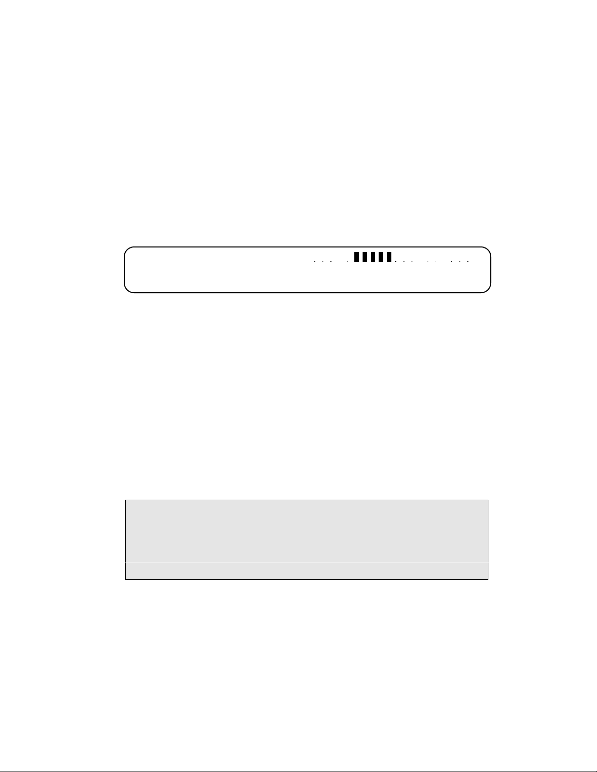
Meter Display (18-0037) AM8a Instruction Manual
Vt-r dc = - 48.1
Vr-g ac = 0.5 60.0 Hz
The mode and units of measure are indicated to the far left. The actual measured value is then
displayed numerically as well as graphically. The DC graph's "0" point is in the center of the
graph. For a negative measurement, the graph lies to the left. For positive measurements, the
graph lies to the right. The SCALE should be set so the graph will obtain the best resolution
based on the anticipated measurements.
6.3 METER SELECTIONS AND CONNECTIONS
Sub-sections 6.4 through 6.11 describe the different meter selections. The possible selections
that can be used depend on the Trunk Type programmed in the CONFIG'N Setup menus which
also determines which Front Panel jacks are active.
Figure 6-1 shows the cables that can be used to make measurements. Usually the 48–0062
cable(s) is used for Analog Measurements, while the 48-0047 and 48-0048 cables are used for
PCM Measurements. The Bantam or PL310 plug may be plugged into jacks on a monitoring
panel at a DSX.
NOTE: A 48-0131 (bantam to bantam) or 48-0157 (bantam to miniclip) Monitor
Cable should be used for RX monitor connections to a DSX if the DSX
monitor jacks are not provided with isolating resistors. These cables have
internal resistors and their external appearance is similar to those shown
in Figure 6-1, except for identifying label.
The 48-0047 cable(s) is also used to interconnect the AM8a with an AM5XT via the TIMS
TX/2W and RX jacks, for detailed measurements of circuit impairment. TIMS connections are
described and illustrated in a separate sub-section.
Figure 6-2 illustrates the measurements that can be taken when the clip leads are connected to
CO circuits if a 48-0062 cable is connected to the LOOP jack illustrated at the top of the
Figure. This figure is designed to provide a quick reference for the user connecting the clip
leads on the cable to the appropriate circuits of a line or trunk. Figure 6-3 similarly shows the
E & M/SS Connections.
February 10, 2000 0037-S06.L_
6-2
Page 72
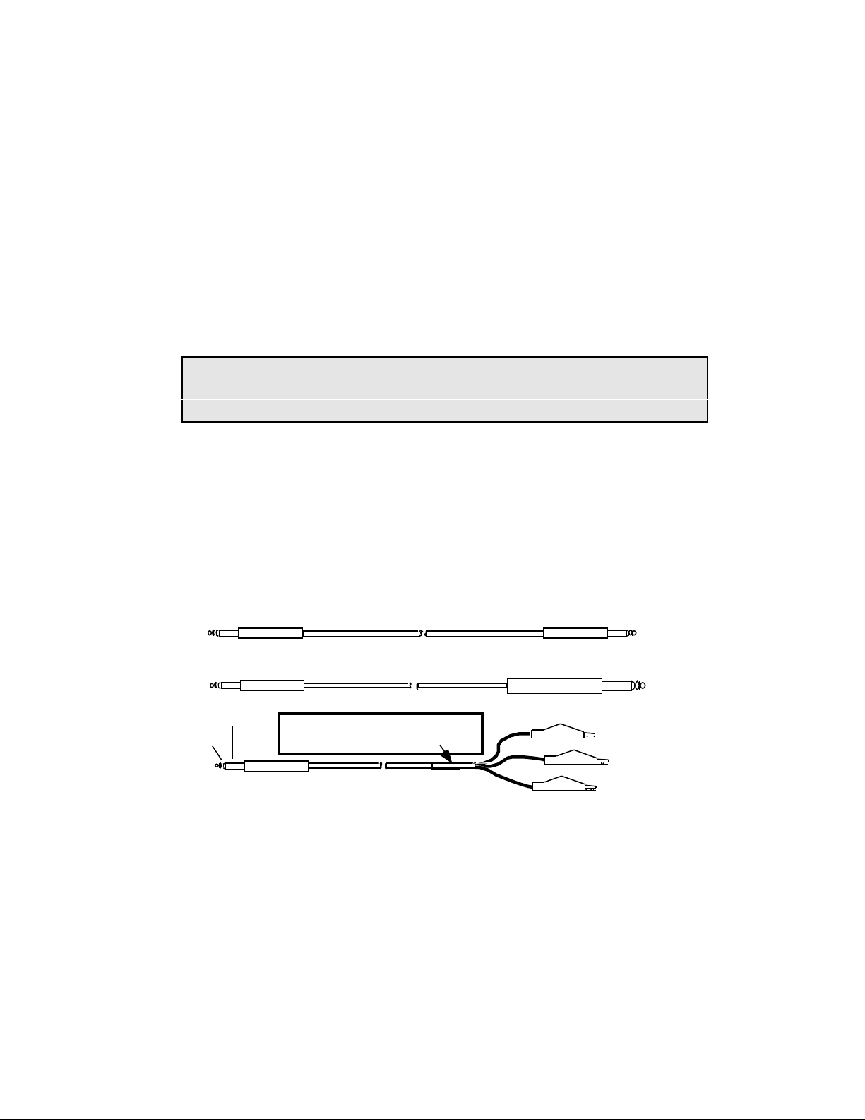
AM8a Instruction Manual (18-0037) Meter Display
NOTE: Color codes for clip leads on 48-0062 cables have been revised from previous
issue to show cables manufactured after 7 May 1992. Further information on
Figure 6-1.
Figure 6-4 shows the PCM1 and PCM 2 Connections. Because PCM connections at a CO are
usually brought out to jacks for Bantam or 310 plugs, plugs are shown in this figure.
There are Pins on the rear panel DB-24F Connector, labeled LINE/TIMS, that correspond to the
contacts on the front panel jacks. In Figures 6-2 through 6-4 these pin numbers are shown
circled for ease of reference. There is also a rear panel binding post labeled CO GROUND in
addition to the connections on the LINE/TIMS connector.
Rear-panel connections allow the user to "hard-wire" the AM8a into an exchange. The user
must provide a cable wired to a matching DB 24M connector if the LINE/TIMS connector is to
be used. A view of the rear panel (and connector pin identifications) is shown in Section 7.
BANTAM PLUG
BANTAM PLUG
sleeve
ring
tip
BANTAM PLUG
CABLE 48-0047, 6 FT.
CABLE 48-0048, 6 FT.
NOTE: Cables manufactured before 5/7/92
are Green (Ring - r) and RED (Tip - t) and
will not have this color-code label
CABLE 48-0062, 6 FT.
BANTAM PLUG
310 PLUG
RED (Ring — r)
GREEN (Tip— t)
BLACK (Sleeve—g)
Figure 6-1. Cables for AM8a Front Panel Test/Meter Connections
0037-S06.L_43 February 10, 2000
6-3
Page 73
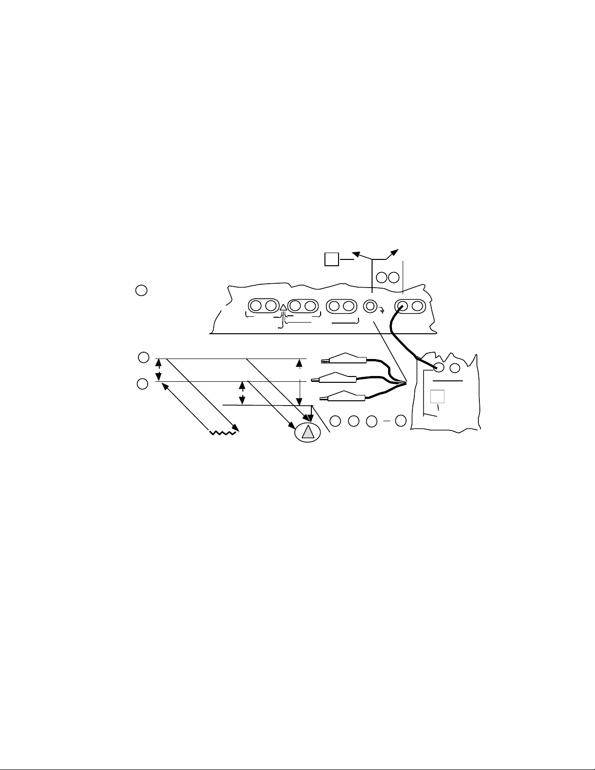
Meter Display (18-0037) AM8a Instruction Manual
10, <330>, 430 ohms
It(ma) dc
24
21
1615
14
13
CO Ground
Noise
are pin numbers on
rear panel LINE/TIMS
connector.
n
TX/2W RX
RX TX/2W
bridging
terminated
Z
•
•
19 20
Vt–r
Tone,
AM8a Terminates line in
Emulate Mode. Bridges
line in Monitor mode.
TX RX TX/2W RX
!
PCM2
CAUTION: 10 VOLTS MAX
PCM1
TRUNK INPUTS
Vr–g
monitor
Z
E/M
E & M
RED (Ring—r)
GREEN (Tip—t)
•
•
• • •
emulate
T/R
SB/SG
LOOP
TIMS
Connection made to
TIMS TX/2W jack
by the TIMS key
([SHIFT] [#, ST])
TX/2W RX
TIMS
To TIMS
(AM5XT Shown)
Vt–g
BLACK (Sleeve—g)
V cm
Figure 6-2. Loop/Ground Start and DID Analog Test/Meter Front Panel Connections
February 10, 2000 0037-S06.L_
6-4
Page 74
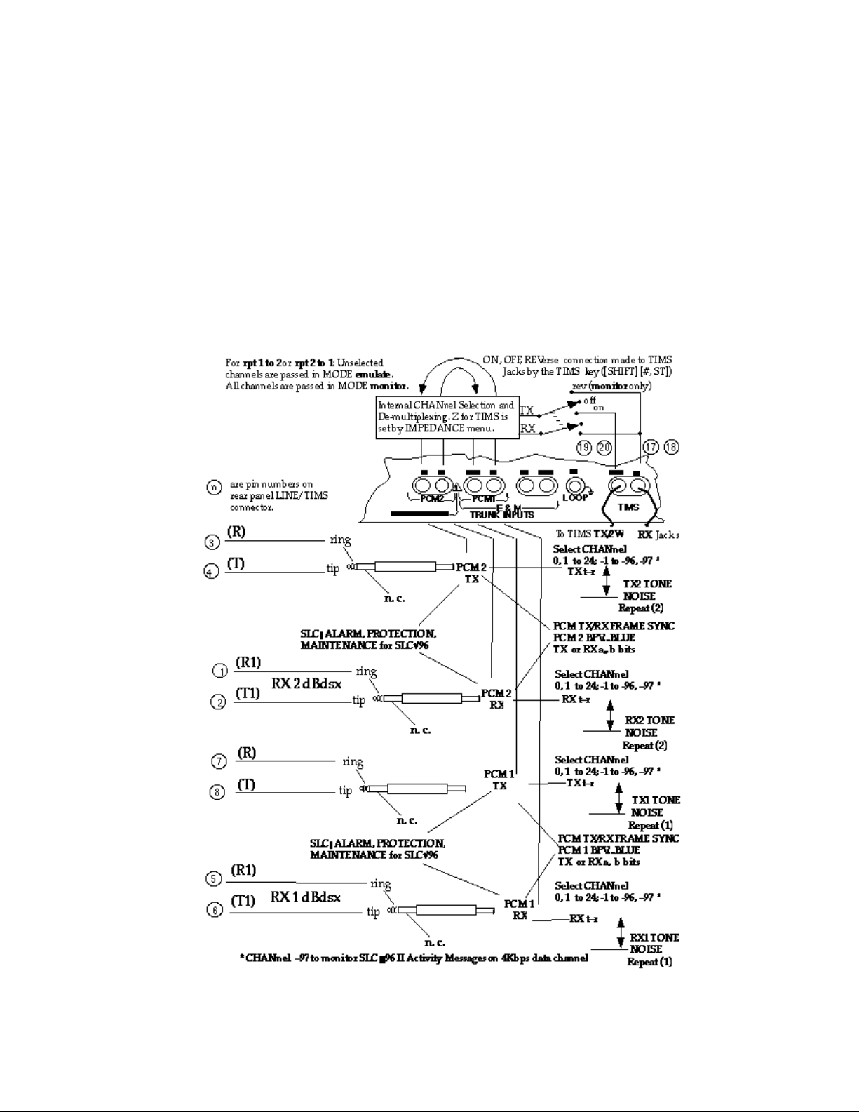
AM8a Instruction Manual (18-0037) Meter Display
Figure 6-3. E & M and SF Test/Meter Front Panel Connections
0037-S06.L_43 February 10, 2000
6-5
Page 75
Meter Display (18-0037) AM8a Instruction Manual
For rpt 1 to 2 or rpt 2 to 1: Unselected
channels are passed in MODE emulate.
All channels are passed in MODE monitor.
are pin numbers on
n
rear panel LINE/TIMS
connector.
(R)
3
(T)
4
ring
tip
Internal CHANnel Selection and
De-multiplexing. Z for TIMS is
set by IMPEDANCE menu.
TX RX TX/2W RX E/M SB/SG
PCM2
CAUTION: 10 VOLTS MAX
ON, OFF, REVerse connection made to TIMS
Jacks by the TIMS key ([SHIFT] [#, ST])
!
PCM1
E & M
TRUNK INPUTS
PCM 2
TX
n. c.
SLCç ALARM, PROTECTION,
MAINTENANCE for SLC
(R1)
1
2
(T1)
RX 2 dBdsx
ring
tip
96
PCM 2
RX
n. c.
(R)
7
(T)
8
ring
tip
PCM 1
TX
n. c.
SLC
ç ALARM, PROTECTION,
MAINTENANCE for SLC
(R1)
5
RX 1 dBdsx
(T1)
6
ring
tip
96
PCM 1
n. c.
* CHANnel –97 to monitor SLC®96 II Activity Messages on 4Kbps data channel
rev (monitor only)
•
TX
RX
RX
•
•
•
•
•
•
19
T/R
LOOP
To TIMS TX/2W
Select CHANnel
0, 1 to 24; -1 to -96, -97 *
TX t–r
PCM TX/RX FRAME SYNC
PCM 2 BPV...BLUE
TX or RX a,, b bits
Select CHANnel
0, 1 to 24; -1 to -96, –97 *
RX t–r
Select CHANnel
0, 1 to 24; -1 to -96, –97 *
TX t–r
PCM TX/RX FRAME SYNC
PCM 1 BPV...BLUE
TX or RX a, b bits
Select CHANnel
0, 1 to 24; -1 to -96, –97 *
RX t–r
off
on
20 17 18
TX/2W
RX
TIMS
TX2 TONE
NOISE
Repeat (2)
RX2 TONE
NOISE
Repeat (2)
TX1 TONE
NOISE
Repeat (1)
RX1 TONE
NOISE
Repeat (1)
•
RX Jack s
Figure 6-4. PCM T1/SLC®96 Test/Meter Front Panel Connections
February 10, 2000 0037-S06.L_
6-6
Page 76

AM8a Instruction Manual (18-0037) Meter Display
6.4 LOOP START, GROUND START, DID – ANALOG MEASURE
The measurements described in sub-sections 6.4.1 through 6.4.6 are made at the LOOP jack on
the front panel using a 48-0062 cable. The DC and AC MEASURE selections described are
listed below in the order presented (beginning at top of left column) as the MENU up key is
pressed:
Description of Measurements
Tone ac tip-ring tone (dBm and Hz)
Vt-r dc Vt-r ac tip-ring voltage
Vcm dc Vcm ac tip & ring common mode
Vt-g dc Vt-g ac tip-ground voltage
Vr-g dc Vr-g ac ring-ground voltage
It(ma) dc tip (loop) current
6.4.1 V t-r dc or ac: These selections place the meter across the Tip and Ring leads of the
Loop input jack (the line). DC measurements result in the voltage displayed
numerically and on the bar graph. AC measurements display the voltage numerically
and graphically and give a frequency measurement.
6.4.2 V cm dc or ac: These selections measures the voltage difference or delta between the
Tip and Ring leads (∆V) of the LOOP input jack. The differential voltage measured is
referenced to CO ground which is connected to the sleeve lead, or can be connected to
a binding post on the rear of the unit.
6.4.3 V t-g dc or ac: These selections place the meter across the Tip lead with reference to
the Ground supplied on the sleeve of the LOOP input jack. The measurements are
displayed in the same manner as V t-r measurements.
6.4.4 V r-g dc or ac: These selections place the meter across the Ring lead with reference to
the Ground supplied on the sleeve of the LOOP input jack. The measurements are
displayed in the same manner as V t-r measurements.
6.4.5 It (mA) dc: This selection places the meter in series with the Tip lead of the LOOP input
jack. The measurement will be displayed numerically and graphically representing the
Loop current being drawn by the Terminal/Line equipment.
0037-S06.L_43 February 10, 2000
6-7
Page 77
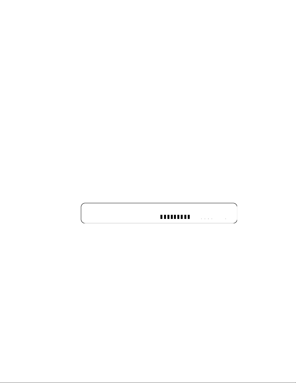
Meter Display (18-0037) AM8a Instruction Manual
Tone = - 10 dBm 1004 Hz
Vt-r dc = - 38.9
The current measurement circuit has a 500mA slow blow fuse in series with the Tip
sense circuit. Excessive current will open the fuse and disable the current
measurements. See Section 1 for instructions on fuse replacement.
When performing current measurements, holding resistance of 10Ω, 330Ω, or 430Ω
can be selected. With the two higher-resistance settings, the measured current may
drop after 10 minutes hold time due to heating of the line feed inductor.
6.4.6 Tone: This selection is used to measure Level and Frequency of Tones present on the
Tip and Ring of the LOOP input jack. The Level is displayed in dBm and the frequency
is displayed in Hz. A measured value of "UNDER" in the Level display indicates the
measurement is lower than the acceptable limit. (dBm < -40). The measure display for
the tone selection is as follows:
February 10, 2000 0037-S06.L_
6-8
Page 78

AM8a Instruction Manual (18-0037) Meter Display
6.5 E & M and SF – ANALOG MEASURE
For E & M the measurements described in sub-sections 6.5.1 through 6.5.5 are made at the E &
M jacks labeled TX/2W, RX, E/M and SB/SG on the front panel. For SF only the TX and RX
jacks and measurements apply. Use as many 48–0047, 48-0048, or 48–0062 cables as are
needed. The DC and AC MEASURE selections described are listed below in the order presented
(beginning at top of left column) as the MENU up key is pressed:
Description of Measurements
TX Tone transmit tip-ring tone (dBm and Hz)
RX Tone receive tip-ring tone (dBm and Hz)
TX Vt-r dc TX Vt-r ac transmit tip-ring voltage
TX Vcm dc TX Vcm ac transmit tip & ring common mode
RX Vt-r dc RX Vt-r ac receive tip-ring voltage
RX Vcm dc RX Vcm ac receive tip & ring common mode
Ve dc Ve ac E-lead tip-ground voltage
Vsg dc Vsg ac SG-lead ring-ground voltage
Vm dc Vm ac M-lead ring-ground voltage
Vsb dc Vsb ac SB-lead tip-ground voltage
6.1.1 TX Vt-r or RX Vt-r, dc or ac: These selections connect the meter across the Tip and Ring
leads of the E & M TX/2W or RX jack. DC measurements result in the voltage displayed
numerically as well as on the bar graph. AC measurements display the voltage
numerically and graphically, and also give a frequency measurement.
6.5.2 TX Vcm or RX Vcm, dc or ac: These selections measure the voltage difference or delta
between the Tip and Ring leads (∆V) of the E & M TX/2W or RX input jack. The
differential voltage measured is referenced to CO ground which must be connected to a
binding post on the rear of the unit.
6.5.3 Ve or Vm, dc or ac: These selections place the meter across the E or M lead with
reference to the Ground supplied on the sleeve of the E/M input jack. DC
measurements result in the voltage displayed numerically as well as on the bar graph.
AC measurements display the voltage numerically and graphically and also give a
frequency measurement.
0037-S06.L_43 February 10, 2000
6-9
Page 79

Meter Display (18-0037) AM8a Instruction Manual
6.5.4 Vsb or Vsg, dc or ac: These selections place the meter across the SB or SG lead with
reference to the Ground supplied on the sleeve of the SB/SG input jack. DC
measurements result in the voltage displayed numerically as well as on the bar graph.
AC measurements display the voltage numerically and graphically and also give a
frequency measurement.
6.5.5 TX Tone or RX Tone: These selections are used to measure Level and Frequency of
Tones present on the Tip and Ring of the TX/2W or RX input jack. The Level is
displayed in dBm and the frequency is displayed in Hz. A measured value of "UNDER"
in the Level display indicates the measurement is lower than the acceptable limit (dBm
< -40). The tone display is similar to the one shown under 6.4.6.
February 10, 2000 0037-S06.L_
6-10
Page 80

AM8a Instruction Manual (18-0037) Meter Display
6.6 E & M and SF – ANALOG MEASURE
The measurements described in sub-sections 6.6.1 through 6.6.7 are made at the PCM1 jacks
labeled TX/2W and RX, and the PCM2 jacks labeled TX or RX on the front panel. Use as many
48-0047, or 48-0048 cables as are needed. The MEASURE selections described are listed in
the order presented (beginning at top of left column) as the MENU up key is pressed:
Description of Measurements
TX1 Vcm dc TX1 Vcm ac PCM1 Transmit tip & ring common mode
RX1 dBdsx PCM1 Received tip-ring bipolar amplitude
RX1 Vcm dc RX1 Vcm ac PCM1 Receive tip & ring common mode
TX2 Vcm dc TX2 Vcm ac PCM2 Transmit tip & ring common mode
RX2 dBdsx PCM2 Received tip-ring bipolar amplitude
RX2 Vcm dc RX2 Vcm ac PCM2 Receive tip & ring common mode
TX1 Tone PCM1 Transmit CHANnel tone (DBm and Hz)
RX1 Tone PCM1 Receive CHANnel tone (DBm and Hz)
TX2 Tone PCM2 Transmit CHANnel tone (DBm and Hz)
RX2 Tone PCM2 Receive CHANnel tone (DBm and Hz)
6.6.1 TX1 Vcm or TX2 Vcm, dc or ac: These selections measure the voltage difference or
delta between the Tip and Ring leads (∆V) of the PCM1 TX or PCM2 TX input jack. The
differential voltage measured is referenced to CO ground which can be connected to a
binding post on the rear of the unit.
6.6.2 RX1 Vcm or RX2 Vcm, dc or ac: These selections measure the voltage difference or
delta between the Tip and Ring leads (∆V) of the PCM1 RX or PCM2 RX input jack. The
differential voltage measured is referenced to earth ground rather than CO ground. The
differential voltage measured is referenced to CO ground which can be connected to a
binding post on the rear of the unit.
6.6.3 TX1 Tone or TX2 Tone: These selections are used to measure Level and Frequency of
Tones present on the selected channel of the PCM1 TX or PCM2 TX input jack. The
Level is displayed in dBm and the frequency is displayed in Hz. A measured value of
"UNDER" in the Level display indicates the measurement is lower than the acceptable
limit. (dBm < -40).
0037-S06.L_43 February 10, 2000
6-11
Page 81
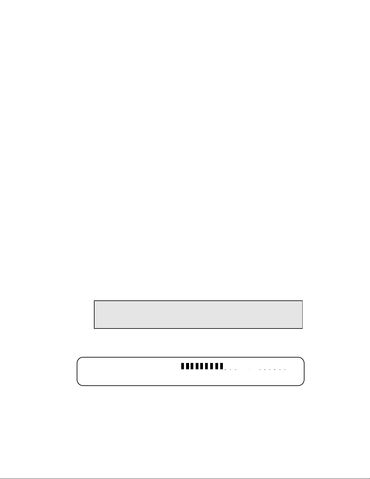
Meter Display (18-0037) AM8a Instruction Manual
6.6.4 RX1 Tone or RX2 Tone: These selections are used to measure Level and Frequency of
Tones present on the selected channel of the PCM1 RX or PCM2 RX input jack. The
Level is displayed in dBm and the frequency is displayed in Hz. A measured value of
"UNDER" in the Level display indicates the measurement is lower than the acceptable
limit. (dBm < -40).
6.6.5 RX1 dBdsx or RX2 dBdsx: These selections are used to measure the received bipolar
amplitude of the PCM signals from the DSX bay at the PCM1 RX or PCM2 RX jack. The
measured value is dependent on the Test Set MODE of the AM8a as described in 6.6.6
and 6.6.7.
6.6.6 RX1 dBdsx or RX2 dBdsx in Emulation Mode: When in EMULATE, the PCM1 or PCM2 RX
jack is connected to the RX jack at the DSX. The measurement will have zero gain
compensation added to the measurement.
6.6.7 RX1 dBdsx or RX2 dBdsx in Monitor Mode: When in MONITOR, the AM8a PCM1 or
PCM2 RX jack is connected to the DSX Monitor jack. The measured value will have a
gain compensation added to compensate for the signal attenuation of the 430Ω resistors
in the DSX monitor jack.
NOTE: This applies also to measurements made while in a Drop & Insert
Configuration (Rpt 1 to 2 or Rpt 2 to 1) since Drop & Insert also must
have both RX jacks connected to the Monitor jacks of the DSX.
6.7 NOISE MEASURE
This MEASURE display is available for all Trunk types.
NOISE 65 dBrn
INPUT TX FILTER CMSG
The display measures the Idle-Channel Noise between Tip and Ring of any selected LOOP, RX
or TX jacks, except for PCM. On PCM, the measurement is made internally on any of the 24
selectable TX or RX channels.
February 10, 2000 0037-S06.L_
6-12
Page 82
AM8a Instruction Manual (18-0037) Meter Display
PCM2 : BPV FERR CRC SLIPS YELLOW BLUE
CNT 64 8 0 0 0 0
PCM1 :
STATUS :
BLUE
NO
YES
YELLOW
NO
YES
or
or
PCM2 :
STATUS :
YELLOW
NO
YES
or
or
BLUE
NO
YES
There are two filters available for noise weighting of the noise measurement. The FLAT filter
will have 0 dB of attenuation of the noise on the line up to 3500 Hz. The CMSG filter has
weighting characteristics that are suitable for voice circuits.
6.8 PCM 1 and PCM 2 BIPOLAR VIOLATION (COUNT AND STATUS) MEASURE
There are two count (CNT) measure displays for the number of Bipolar Violations, Frame
Errors, CRC errors, Slips, Yellow, and Blue alarms.
Two additional STATUS displays indicate if BLUE or YELLOW alarm conditions have occurred.
These displays are for measurements taken at the PCM1 or PCM2 TX or RX jacks and are
shown in the order of MENU up arrow selection:
PCM1 : BPV FERR CRC SLIPS YELLOW BLUE
CNT 512 8 0 0 0 0
Sub-sections 6.8.1 through 6.8.6 describe each measurement on the CNT displays, and subsections 6.8.7 and 6.8.8 describe the measurements on the STATUS displays.
6.8.1 BPV: counts in increments of 64. This results in a change for every 64 BPV
occurrences. A BPV occurs when two consecutive "1" pulses have the same polarity.
0037-S06.L_43 February 10, 2000
6-13
Page 83

Meter Display (18-0037) AM8a Instruction Manual
6.8.2 FERR: counts frame errors in increments of 4. The result is a change every fourth
Frame error. A Frame error occurs when an incorrect bit occurs as the frame bit.
6.8.3 CRC: is used only in an ESF framing mode. The resolution of the counter is 1. A CRC
is counted when the calculated CRC on the receiver (AM8a) does not match the CRC
sent as part of the next ESF.
6.8.4 SLIPS: counts the number of times there is an insertion or deletion of data bits in the
data stream. A slip is commonly due to buffer overflow or underflow of the network
equipment.
6.8.5 YELLOW: counts the number of yellow alarms received from the transmitting
equipment indicating the loss of synchronization to its received signal. The AM8a will
count a yellow alarm when this condition exists for more than 600ms. Once the yellow
alarm condition is removed, the condition must be absent for a 200ms blanking
interval. The conditions for YELLOW are:
• For D3/D4 framing, bit 2 set to a "zero" for all 24 time slots.
• For ESF, the yellow alarm is generated by a 16 bit stream, 8 "1" bits followed by 8
"0" bits. The same timing conditions as D3/D4 are used.
6.8.6 BLUE: counts the number of blue alarm conditions detected. The blue alarm is present
when two (2) frames of "1" bits and an out-of-frame condition exists.
6.8.7 STATUS BLUE: is YES when the receiver has detected two (2) frames of "1"s and an
out-of-frame condition (refer to 6.8.6, above).
6.8.8 STATUS YELLOW: is YES when the receiver has detected a "0" in the bit 2 positions of
every DS1 channel (for further definition refer to 6.8.5).
6.9 PCM 1 OR PCM 2 FRAME SYNC MEASURE
This display allows the user to monitor the phase relationship between the spans connected to
the PCM1 RX and TX jacks or the PCM2 RX and TX jacks. The indication should remain stable
without any change or jitter occurring.
PCM TX FRAME SYNC:
PCM RX FRAME SYNC:
February 10, 2000 0037-S06.L_
6-14
Page 84
AM8a Instruction Manual (18-0037) Meter Display
The user may align the indicators by pressing [SHIFT] then [CANCEL] for better comparison.
This display is also used for Drop & Insert (Rpt 1 to 2 or Rpt 2 to 1) testing.
6.10 PCM 1 OR PCM 2 TX OR RX A/B MEASURE
This display provides a view of the signaling bits of all 24 time-slots for both the transmit
and receive T1 and SLC®96 I (Mode I) Spans.
CAUTION: This display is only valid when the AM8a is in MONITOR mode. Readings
are meaningless in EMULATE mode.
TX A B
RX A B
An A-bit or B-bit indication, shown by a shaded rectangle, means that the time-slot is active.
Time-slot 01 is the bit to the far left and time-slot 24 is to the far right of the display.
Dots are displayed in all bit positions (shown for illustration only in slot 7-12 locations) if the
AM8a is in an invalid mode for this display.
This display is useful for locating an idle voice channel before running Drop & Insert tests.
Select a time-slot which displays inactive status in monitor mode before the selection of
emulate mode to run the test (Rpt 1 to 2 or Rpt 2 to 1).
6.10.1 T1 Time-Slot to Voice Channel Assignment: For T1 spans, the time-slot is equivalent to
the channel number. This display is not used for SLC®96 Mode II.
6.10.2 SLC®96 Mode I Time-Slot to Voice Channel Assignment: Refer to Figure 6-5 for the
assignment of voice channels to time slots for SLC®96 Mode 1.
6.10.3 SLC®96 Mode II Time-Slot to Voice Channel Assignment: The TX or RX A/B Measure
display is not useful for SLC®96 Mode II. Assignment of Time-Slots to Voice
Channels is dynamic in SLC®96 Mode II. To determine which voice channel is active,
refer to the Concentrator Field Message (a and b events) which can be monitored on
the data link (CHAN=–97). For further details refer to Sections 1.2.2, 2.5.3, and
2.5.4.
• • • • • •
• • • • • •
0037-S06.L_43 February 10, 2000
6-15
Page 85
Meter Display (18-0037) AM8a Instruction Manual
NOTE: Active RX and TX test channels and time slots can also be determined by
display of the Maintenance Message, described in sub-section 6.11.3.
®96 Mode I Channel Number Assignment by Shelf
Time
Slot
01
02
03
04
05
06
07
08
09
10
11
12
13
14
15
16
17
18
19
20
21
22
23
24
SLC
A
01
13
02
14
03
15
04
16
05
17
06
18
07
19
08
20
09
21
10
22
11
23
12
24
B
25
37
26
38
27
39
28
40
29
41
30
42
31
43
32
44
33
45
34
46
35
47
36
48
C D
49
61
50
62
51
63
52
64
53
65
54
66
55
67
56
68
57
69
58
70
59
71
60
72
73
85
74
86
75
87
76
88
77
89
78
90
79
91
80
92
81
93
82
94
83
95
84
96
CHAN parameter in PCM CONFIG 1 menu selects either Time
Slot or Channel Number (prefaced by – sign). 0-entry will
cause monitoring of first time slot that becomes active
(assigned channel goes off-hook).
Figure 6-5. SLC®96 Mode 1 Channel Number to Time Slot Assignments
February 10, 2000 0037-S06.L_
6-16
Page 86
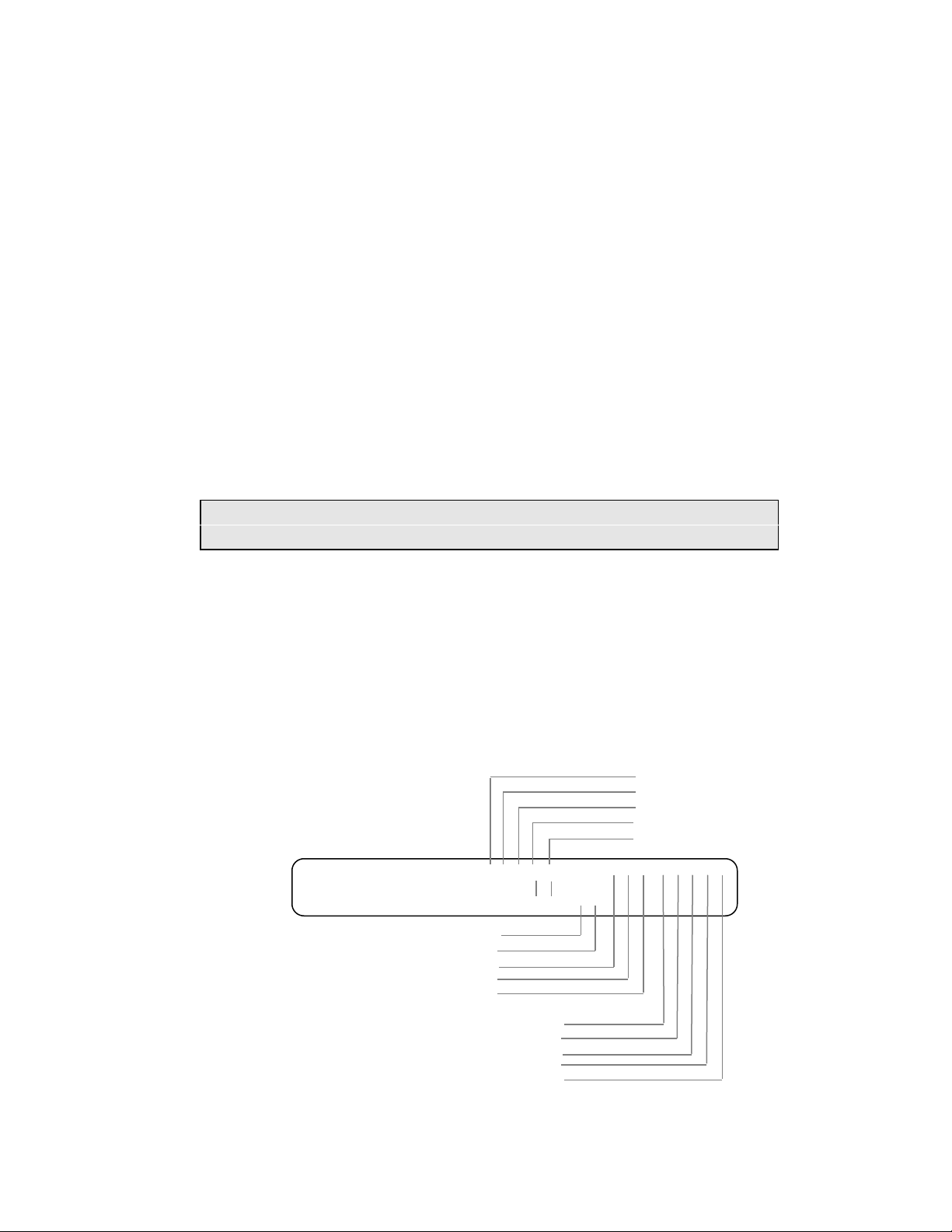
AM8a Instruction Manual (18-0037) Meter Display
6.11 SLC®96 MODE I OR II MESSAGES
When the AM8a is monitoring the RX or TX lines of a SLC®96 I or II (Mode I or Mode II) PCM
link, three additional metering displays are available. These displays are the result of the
decoding of bits in the PCM data stream.
NOTE: A SLC®96 RX line or TX line is also referred to as a "half-span" in some PCM
descriptions.
6.11.1 ALARM TX or RX: provides an indication of alarm conditions detected on the link. For
both TX and RX, there are two variations of the metering format. The one displayed is
dependent on how the monitored switch is equipped.
The upper display shows 15 conditions which can be reported by the position of an
"A". The lower display shows 10 conditions. (In an actual display both lines will
usually have the same format.)
Figure 6-6 shows the display and identifies the Alarm Conditions. This is a dynamic
display which will change as alarms occur. Alarm messages also will be printed via
the RS 232 port.
Not Used
Not Used
Not Used
Major Alarm
Minor Alarm
ALARM TX
ALARM RX
09/21/93
Power/Misc. Alarm
A-Shelf Alarm
B-Shelf Alarm
C-Shelf Alarm
D-Shelf Alarm
– – – AA AA – – – – – – – –
– – AA – – – – – – – –
A-Line Far-End Loop
B-Line Far-End Loop
C-Line Far-End Loop
D-Line Far-End Loop
P-Line Far-End Loop
Figure 6-6. SLC®96 Alarm Conditions Meter Display
0037-S06.L_43 February 10, 2000
6-17
Page 87
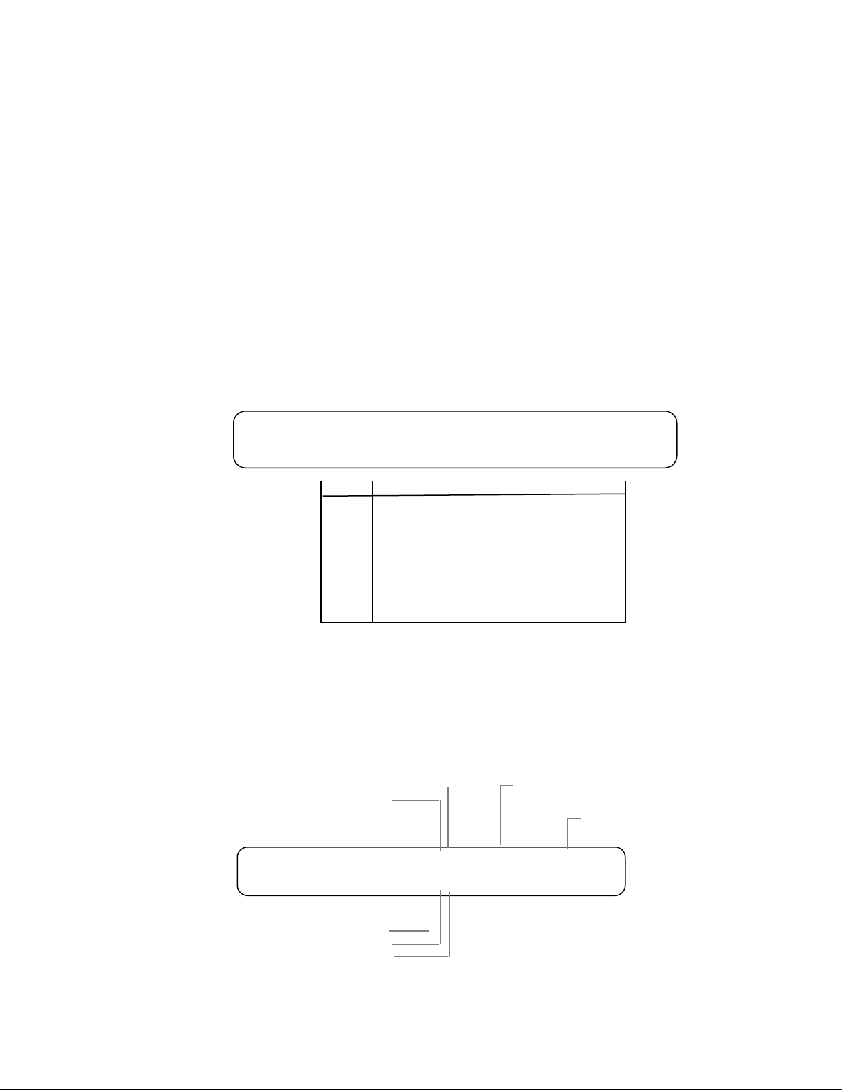
Meter Display (18-0037) AM8a Instruction Manual
6.11.2 PROTECTION TX or RX: provides an indication of protection settings for the link.
Figure 6-7 shows the display and interprets the conditions represented by the "0" or
"1" states of the display.
PROTECTION TX
PROTECTION RX
display
1111
1110
1101
1100
1010
0101
0100
0010
IDLE
SWITCH LINE A RECEIVE
SWITCH LINE B TRANSMIT
SWITCH LINE C TRANSMIT
SWITCH LINE D TRANSMIT
SWITCH LINE B TRANSMIT & RECEIVE
SWITCH LINE C TRANSMIT & RECEIVE
SWITCH LINE D TRANSMIT & RECEIVE
1111
1111
Message
Figure 6-7. SLC®96 Alarm Conditions Meter Display
6.11.3 MAINTENANCE TX or RX: provides a display of status of maintenance messages for
the link. The interpretation of the RX and TX displays depends upon whether the unit
is functioning as a te/line (RT) or as a switch (LDS).
Figure 6-8 shows the display, and interprets the conditions represented by "0" or "1"
states for either direction. This display also shows the channels and time-slot
assignments during the test operation.
TEST ALARM CR
PROCEED CR
ON HOOK
0=No message
1=RX/TX Message from LDS to RT
MAINTENANCE TX
MAINTENANCE RX
111
000
CHNL=xx TS=xx
CHNL=xx TS=xx
Channel Test
00= inactive
01 - 48 = Channel
Time Slot
00= inactive
01 - 24 = Time Slot
0=No message
RX/TX Message from RT to LDS1=
SEIZE
PROCEED RC
TEST ALARM RC
NOTE:
LDS means Local Data Switch
RT means Remote Terminal
Figure 6-8. SLC®96 Alarm Conditions Meter Display
February 10, 2000 0037-S06.L_
6-18
Page 88

AM8a Instruction Manual (18-0037) Meter Display
6.11.4 SLC®96 II Concentrator Field Messages: can be displayed as events when monitoring
operations between a remote terminal (RT) and a local data switch (LDS). Events are
generated as trunks are assigned or de-assigned, loop tests are run, and activities are
reported and updated. The 4kBps data channel (CHAN=–97) must be selected. Refer
to Sections 1.2.2, 2.5.3, and 2.5.4.
0037-S06.L_43 February 10, 2000
6-19
Page 89

Meter Display (18-0037) AM8a Instruction Manual
February 10, 2000 0037-S06.L_
6-20
Page 90

AM8a Instruction Manual (18-0037) RS232 Entries and Printouts
7. RS232 ENTRIES AND PRINTOUTS
This section describes the RS232 commands that are equivalent to functions actuated by keys
on the AM8a front panel. Also described are the printouts of SETUP menus,
EVENTS/DETAILS, METER displays, LED displays, and AUTO PRINT reports. Finally, this
section describes the RS232 connections for a terminal and for chained operation of more than
one unit.
7.1 RS232 COMMAND DESCRIPTION
Functions activated by front panel keys (described in the previous sections) may also be
executed by a terminal or computer connected to the RS232 port on the rear panel. The
following rules apply to RS232 Commands:
• An RS232 command is initiated by a "(" and executed when a ")" is received. The
")" may also be used alone to repeat the last command sent. Only the characters between
the "(" and the ")" are recognized as a command. (Other control characters, such as
carriage return <CR> and line feed <LF> are not required and will be ignored.)
• An "=" sign precedes a value change in SETUP commands.
• A help menu may be displayed by typing "?". As directed in the menu, "1" through
"6" can then be typed to get additional information.
• The AM8a echoes all characters received after it has processed them. The echo may
be disabled if required, but leaving echo enabled is recommended while computer downloading, for output control and error checking purposes.
• A computer's down-load program should be setup to wait for the echo of the
previously sent character prior to sending the next character. This ensures the AM8a has
had adequate time to process the command and prevent a buffer overflow. This also
prevents loss of data which may cause down-load failure.
• The first letter of many commands corresponds to pressing a key on the front panel for
that function (e.g. "C for CONFIG'N, "E" for EMULATE, "A" for ANALYZE). Other
commands may abbreviate a key and its action e.g: "SZ+" for SEIZE ON).
0037-S07.L_58 February 10, 2000
7-1
Page 91

RS232 Entries and Printouts (18-0037) AM8a Instruction Manual
• Front panel key actions which are alternate-action toggles are controlled by a "+" for
ON or "–" for OFF. For PCM monitoring, the TIMS key has a three-position selection that
uses a "#", (e.g: "TI+" for TIMS ON, "TI#" for TIMS reverse jack connections, and "TI–" for
TIMS OFF).
• Display menus will change as some commands are entered (unless the display has
been deactivated by an "(AY-)" command). A display can be printed with a (PDS) printdisplay command.
• If units are chained, the command "!u" (where u=A through O corresponding to
units 1 through 15) must precede commands to the unit (refer to 7.3.3).
7.1.1 Terminal Commands: The RS232 terminal commands are shown in Figure 7–1. These
commands do not correspond to keys on the unit. They control the interaction between
the terminal (or computer) and the RS232 port. Refer to 7.3.2 for information on
connecting terminal to unit.
7.1.2 Printer Commands: (PDS) and other commands for printing are listed in Figure 7-2.
This figure also identifies equivalent front panel actions. The formats of the printouts
are shown in the Figures described under 7.2.
7.1.3 SETUP Menu Commands for CONFIG, EMULATE, and ANALYZE: The RS232 SETUP
Menu commands are listed Figures 7-3, 7-4, and 7-5, which also provide a quick
reference to the Section 2, 3, and 4 sub-sections that provide detailed descriptions of
menu displays and parameter entries. These commands are the equivalent to front
panel key actions after the operator activates the [CONFIG'N], [ANALYZE], or
[EMULATE] key functions.
February 10, 2000 0037-S07.L_
7-2
Page 92

AM8a Instruction Manual (18-0037) RS232 Entries and Printouts
7.1.3.1 Display Menu: To display a menu, type a command that corresponds to any
parameter within that menu. The menu will then be displayed on the AM8a. For
example: (CTD) or (CEM) displays the MODE CONFIGURE menu.
7.1.3.2 Change Parameter: To change a parameter, find the command that sets the
parameter within a menu. Type the command then an equal "=" sign. After the
equal sign there are two kinds of values that can be entered, followed by the closing
")".
• A Code Value: This is a code from 00 through 07 (leading "0" may be omitted).
Each code corresponds to a parameter setting that is not numeric, for example
(refer to Figure 7-3):
(CTD=00) or (CTD=0) sets MODE CONFIG: IMITATE to te/line
(CTC=02) or (CTC=2) sets PCM: FRAMING to SLC®96
• A Numeric Value: This is an entry that directly sets a numeric value into the
parameter, for example:
(CSM=1200) sets the CIRCUIT: ANALOG IMPEDANCE to 1200 ohms
7.1.3.3 Print Menu: If not already displayed, the menu with the changed parameter must be
displayed by a (PDS) command. For example, if the DISPLAY CONFIG menu
containing CONTRAST was not displayed when the (CCT=3) command was
entered, type (CCT). To print the displayed menu, follow with (PDS), and the menu
will be printed, showing the parameter value that has been entered:
DISPLAY: MODE CONTRAST BACKLIGHT
CONFIG: new call reset 3 on 5min
7.1.4 AUTO DIAL Setup Commands: The AUTO DIAL Setup key on the front panel permits the
operator to enter up to 10 sequences of auto dialing (also referred to as "Speed Dial").
Details on AUTO DIAL are provided in Section 5. The RS232 equivalents for setting,
storing, recalling, and dialing AUTO DIAL numbers are shown in Figure 7-6. Also
shown are other commands related to dialing as well as the equivalent characters that
are typed for the Data Entry keys for dialed digits (and other dialing sequence
operations).
0037-S07.L_58 February 10, 2000
7-3
Page 93

RS232 Entries and Printouts (18-0037) AM8a Instruction Manual
7.1.5 ON-OFF (Control Toggle) Commands: The RS232 commands that simulate the toggle
action of the keys on the lower-left of the front panel are shown in Figure 7-7. The
"+", "–", and "#" characters following the command letters represent ON status, OFF
status, and (for PCM monitor) reversed inputs. Refer to Section 1 for further
description of the key functions.
7.1.6 CALL INITIATE (Signaling) Commands: The RS232 commands that simulate the actions
of the keys in the upper right side of the front panel are shown in Figure 7-8. The "+",
and "–" keys are used to indicate the key states.
7.1.7 EVENTS DISPLAY Commands: The RS232 commands that simulate the actions possible
after the EVENTS DISPLAY function on the front panel has been activated, are shown in
Figure 7-9. The commands permit the selection of a given event for detail printout,
provide simulation of the
FIELD
keys on the front panel, and simulate the FREEZE
and CANCEL keys.
7.1.8 METER DISPLAY Commands: The RS232 commands that simulate the key actions after
the METER DISPLAY function has been selected are shown in Figure 7-10. The MENU
and MEASURE selections possible are dependent on the CIRCUIT CONFIGURE
selections.
Table 7-1. RS232 Terminal Commands
COMMAND DEFINITION
(Lxxx…x) Log On with password xxx…x: A password is required if the setting of the
CONFIG’N PASSWORD menu is YES. If NO, a password is not required, and the
AM8a acts on RS232 commands as soon as a “?” or “(“ character is received. Setting
of the password is described at the end of this table. (The user may “white it out” of
this manual, if desired.)
(B) Log Off (“Bye”): This command should be entered as soon as the operator is
finished with entering RS232 commands. In any case, there is an automatic Log off if
there is no activity at the RS232 port for a period of two minutes. This is only required
with passwords.
(EC+) Echo On: This is the default status for the RS232 entries. When echo is on, every
character received by the AM8a (on the RX line) results in the AM8a returning the
command on its TX line. A terminal set in full-duplex mode will print the character,
thereby acknowledging that the AM8a has received it. If commands are output from a
computer, the computer program should be written to wait for the echoed character
and check it.
February 10, 2000 0037-S07.L_
7-4
Page 94
AM8a Instruction Manual (18-0037) RS232 Entries and Printouts
COMMAND DEFINITION
(EC-) Echo Off: When echo is off, the AM8a will not echo received characters. A terminal
will have to be set to half-duplex so the operator can monitor what is being entered.
This mode could be used for a high-speed dump of commands by a computer, but is
not recommended because error-checking cannot be implemented.
(AY+) Enable front panel display and keypad: This is the default status for the AM8a.
Any entry made at the keypad or via the RS232 port is displayed. When in operation
as a line monitor or emulator, events are displayed.
(AYK) Disable front panel keypad: This is a “safety” setting which prevents a local
operator at an AM8a from using the keypad to change entries made via the RS232
port; however, the display remains active.
(AY-) Disable front panel display and keypad: This command disables both the display
and the keypad. No further events or entries from the RS232 port will be displayed. If
this command is entered, the only way to control or monitor the AM8a is through the
RS232 port.
(AXYZxxx.x) Set new password xxx…x: The password is 30 characters maximum and can not
contain the characters “,”. “!”, or “?”.
Table 7-2. RS232 Printing Commands
COMMAND DEFINITION
(PDS) Print Display Screen: This command prints both lines of any display which has been
called up by a preceding command.
(PFL) Print Front Panel LEDs: DISPLAY/SETUP mode, INPUT, TIMS, TALK, and AUTO
indicators. Prints the status of the LEDs as ON or OFF. It is equivalent to looking at
LEDs on the front panel.
(PET) Print Events Top Line: This command prints the string of events that are displayed
on the Top Line of the display. It is equivalent to pressing [SHIFT] then [PRINT]
briefly (short print) while the EVENTS DISPLAY function is activated.
(PEB) Print Event Both-lines: This command prints Events and Details. It is equivalent to
pressing PRINT for two seconds (long print) while the EVENTS DISPLAY function is
activated.
(PMO) Print Meter Only: This command forces display of the first METER menu and prints
all meter displays that apply to the METER settings.
(PCO) Print Configuration Only: This command prints all configuration parameters. It is
equivalent to pressing [SHIFT] then [PRINT] briefly (short print) while the SETUP
CONFIG’N DISPLAY function is activated.
(PEO) Print Emulate Only: This command prints all emulation parameters. It is equivalent
to pressing [SHIFT] then [PRINT] briefly (short print) while the SETUP EMULATE
function is activated.
0037-S07.L_58 February 10, 2000
7-5
Page 95
RS232 Entries and Printouts (18-0037) AM8a Instruction Manual
(PAO) Print Analyze Only: This command prints all analyze parameters. It is equivalent to
pressing [SHIFT] then [PRINT] briefly (short print) while the SETUP AUTO DIAL
function is activated.
(PSO) Print Speed/Auto Dial Only: This command prints current auto-dial number. It is
equivalent to pressing [SHIFT] then [PRINT] briefly (short print) while the SETUP
ANALYZE function is activated.
(PAL) Print All SETUP: This command prints all parameters that are appropriate to the
configuration and operating mode. It is equivalent to pressing [SHIFT] then [PRINT]
for two seconds (long print) while any of the SETUP functions are activated.
(POM=nn) Print One Memory (where nn = 0-19 for Configure parameters, nn = 20-39 for Emulate
and Analyze parameters, or nn = 40 for all Power Off Recall parameters. This
command could be issued after doing a store command (Znn). This command is not
the same as doing a recall (Rnn) followed by a (PAL), since operating parameters are
not changed.
Table 7-3. RS232 CONFIGuration Menu Commands
COMMAND DEFINITION
(R0) – (R19) RECALL CONFIG’N SETUPs from location ID 0 through ID 19. [SHIFT] + [RECALL]
+ [location ID] keys.
(R40) RECALL all SETUPs from last power down. [SHIFT] + [RECALL] + [*] keys.
(Z0) – (Z19) STORE CONFIG’N SETUPs from location ID 0 through ID 19. [SHIFT] + [STORE] +
[location ID] keys.
(CTD) MODE: IMITATE. (CTD = 00) for te/line. (CTD = 01) for <switch>. 2.1.1
(CEM) MODE: MODE. (CEM = 00) for emulate. (CEM = 01) for <monitor>. 2.1.2
(CIR) CIRCUIT: ANALOG IMPEDANCE. (CIR) = 135, 600, <900>, or 1200. 2.2.1
(CTA) CIRCUIT: ANALOG/PCM. (CTA = 00) for analog, (CTA = 01) for pcm int clk, (CTA =
02) for <pcm loop clk>. 2.2.2
(CTC) PCM: INPUT. (CTC = 00) for <pcm1 on>, (CTC = 01) for pcm2 on, (CTC = 02) for
rpt1 to 2, (CTC = 03) for rpt2 to 1. 2.3.1 (1)
(CFM) PCM: FRAMING. (CFM = 00) for <D3/D4>, (CFM = 01) for ESF, (CFM = 02) for
SLC®96 I, (CFM = 03) for SLC®96 II. 2.3.2 (1)
(CZS) PCM: ZEROSUP. (CZS = 00) for B8ZS, (CZS = 01) for ZCS, (CZS = 02) for <AMI>.
2.3.3 (1)
(CTH) PCM: CHAN. (CTH = 00) for Channel <0> (random), (CTH = 24) to Channel 24,
(CTH = -97) for SLC® Data link monitor, (CTH = -1) for SLC® Channel 1, (CTH = -
96) to Channel 96. 2.3.4 (1)
(CS1) PCM: OFF HK a/b. (CS1 = 00) for <auto>, (CS1 = 01) for 0/0, (CS1 = 02) for 0/1,
(CS1 = 03) for 1/0, (CS1 = 04) for 1/1, (CS1 = 05) for 0/X, (CS1 = 06) for 1/X, (CS1 =
07) for X/0, (CS1 = 08) for X/1, (CS1 = 09) for. 2.3.5 (2)
February 10, 2000 0037-S07.L_
7-6
Page 96

AM8a Instruction Manual (18-0037) RS232 Entries and Printouts
(CS2) PCM: ON HK a/b. See CS1 list. 2.3.5 (2)
(CTT) TRUNK: TRUNK TYPE. (CTT = 00) for loop start, (CTT = 01) for ground start, (CTT
= 02) for E&M 2W, (CTT = 03) for <E&M 4W>, (CTT = 04) for did, (CTT = 05) for sf.
2.4.1
(CST) TRUNK: SLC® TYPE. (CST = 00) for <SINGLE PARTY>, (CST = 01) for
UNIVERSAL V G. 2.4.2
(CET) TRUNK: E&M TYPE. (CET = 00) for <I>, (CET = 01) for II, (CET = 02) for III, (CET =
03) for IV. 2.4.3
(CDM) DISPLAY: MODE. (CDM = 00) for manual, (CDM = 01) for <new call reset>, (CDM
= 02) for scroll. 2.5.1
(CDI) DISPLAY: DIG DET. (CDI = 00) for wide, (CDI = 01) for <narrow>, (CDI = 02) for
limit. 2.5.2
(CSM) DISPLAY: SLC® MSG. (CSM = 0000000000) to (CSM = 1111111111) for
0000000000 to <0000000001> to 1111111111. 2.5.3
(CMK) DISPLAY: “T/t” MASK. (CMK = 00) for <NO>, (CMK = 01) for YES. 2.5.5
(CBR) RS232: BAUD RATE. (CBR) = 300, 1200, 2400, or <9600>. 2.6.1 (@)
(CPT) RS232: PARITY. (CPT = 00) for <NO>, (CPT = 01) for ODD, (CPT = 02) for EVEN.
2.6.2 (@)
(CCD) RS232: CR DELAY sec. (CCD = 0) for <0> to (CCD = 99) for 99 sec. 2.6.3 (@)
(CPW) SECURITY: PASSWORD. (CPW = 00) for <no>, (CPW = 01) for yes. 2.7.1 (@)
(CSU) SECURITY: SETUP PROTECT. (CSU = 00) for no, (CSU = 01) for <yes>. 2.7.2
(@)
(CAE) PRINT: AUTO< PRINT. (CAE = 00) for <off>, (CAE = 01) for all calls, events onlyt,
(CAE = 02) for all calls, events & details, (CAE = 03) for flawed calls, events only,
(CAE = 04) for flawed calls, events & details. 2.8.1 thru 2.8.5
(CMM) CLOCK: DATE/MM. (CMM = 1) for 1 to (CMM = 12) for 12 (month). 2.9 (@)
(CDD) CLOCK: DATE/DD. (CDD = 1) for 1 to (CDD = 31) for 31 (day of month). 2.9 (@)
(CYY) CLOCK: DATE/YY. (CYY = 0) for 0 to (CYY = 99) for 99 (last 2-digits of year). 2.9
(@)
(CHH) CLOCK: TIME/HH. (CHH = 0) for 0 to (CHH = 23) for 23 (hour). 2.9 (@)
(CMT) CLOCK: TIME/HH. (CMT = 0) for 0 to (CMT = 59) for 59 (minutes). 2.9 (@)
No RS232
Command
AM8a: CPU DSP0 DSP1
105 100 100
Version is local display 2.10
0037-S07.L_58 February 10, 2000
7-7
Page 97

RS232 Entries and Printouts (18-0037) AM8a Instruction Manual
The first two RS232 commands are equivalent to the RECALL and STORE key functions on the
front panel for SETUP selected. The remaining commands are listed in the order of the
equivalent AM8a front panel LCD menu displays as the MENU, FIELD, and VALUE keys are
pressed.
The block to the right of the command shows menu text (sufficient for identification) and the
selection-alternates (as displayed). Default values (factory-supplied) are shown within “<>”;
not part of the menu display.
A command begins with an “(“ followed by a three-letter code and, optionally, an “=” sign,
and either a two-digit code or a parameter value. A command ends with a “)”.
To display a menu, type only a command code for a parameter on the menu; e.g., (CTD) or
(CEM) for the TEST SET: … menu. To print the menu, type the print-display command, (PDS).
To change a parameter, type the command for the parameter, an “=” sign, and a code value
(leading 0 may be omitted). E.g., (CTD=1) to set the MODE:IMITATE to “switch”; or a
parameter value, e.g., (CTH=5) to set the PCM:CHAN to channel 5. Parameter change
commands will not display the menu. If the menu is already displayed, the change will be
seen.
To display a menu that has been changed, enter the display command; e.g., (CTH), type the
print-display command (PDS).
Manual subsection numbers where the parameter is described in detail are shown in bold type
following the parameter description; e.g., 2.1.1. A (1), (2), or a (3) following the subsection
number indicates that an additional menu must be displayed; e.g., PCM CONFIG 1 and PCM
CONFIG 2. An (@) following the subsection number indicates that the parameter must be
changed by the operator, not stored or recalled.
NOTE: MF(R1) digits will not be seen if DIALTONE is used as a Start Signal.
February 10, 2000 0037-S07.L_
7-8
Page 98

AM8a Instruction Manual (18-0037) RS232 Entries and Printouts
Table 7-4. RS232 EMULATE Menu Commands
COMMAND DEFINITION
(R20) – (R39) RECALL EMULATE/ANALYZE SETUPs from location ID 20 through ID 39.
[SHIFT] + [RECALL] + [location ID] keys.
(R40) RECALL all SETUPs from last power down. [SHIFT] + [RECALL] + [*] keys.
(Z20) – (Z39) STORE EMULATE/ANALYZE SETUPs from location ID 20 through ID 39. [SHIFT]
+ [STORE] + [location ID] keys.
(ELV) LOOP: VOLTAGEvdc. (ELV = 20) for 20 to <48> to (ELV = 72) for 72 volts. 3.1.1
(ELL) LOOP: LENGTH ohm. (ELL) = 0, 300, 600, 900, <1200>, 1500, 1800, or 2100.
3.1.2
(EIC) TERMINATION: 2.16uf. (EIC = 00) for <in>, (EIC = 01) for out. 3.2.1
(EDH) TERMINATION: DC HOLD. (EDH) = 10ohm, <330ohm>, or 430ohm. 3.2.2
(ELT) DIALING: LOOP TYPE. (ELT = 00) for <pulse>, (ELT = 01) for dtmf, (ELT = 02) for
mf(R1). 3.3.1
(ESS) DIALING: START SIGNAL. (ESS = 00) for immediate, (ESS = 01) for <wink>,
(ESS = 02) for delay, (ESS= 03) for dial tone. 3.3.2
(EPS) PULSE: SPEEDpps. (EPS) = 5 to <10> to 25. 3.4.1
(EPB) PULSE: BREAK%. (EPB) = 40 to <60> to 85. 3.4.2
(EPI) PULSE: INTRDIGITms. (EPI) = 120 to <600> to 999. 3.4.3
(ET1) DTMF/MF: HI: dBm. (ET1) = -40 to <-7> to -3. 3.5.1 (1)
(ET2) DTMF/MF: HI/hz%. (ET2) = -5.0 to <0.0> to +5. 3.5.1 (1)
(ET3) DTMF/MF: LO: dBm. (ET3) = -40 to <-7> to -3. 3.5.2 (1)
(ET4) DTMF/MF: LO/hz%. (ET4) = -5.0 to <0.0> to +5. 3.5.2 (1)
(EEN) DTMF/MF: ON. (EEN) = -25 to <50> to 99. 3.6.1 (2)
(EEF) DTMF/MF: OFFms. (EEF) = -25 to <50> to 99msec. 3.6.1 (2)
(EHL) SEND TONE: LEVELdBm. (EHL) = -40 to <-10> to 0. 3.7.1
(EHF) SEND TONE: FREQUENCYhz. (EHF) = 300 to <1004> to 3300. 3.7.2
(ED1) DIAL TONE: ON. (ED1) = 0 to <9999>msec (Dial Tone 1 ON-Time). 3.8 (1)
(ED2) DIAL TONE: OFFms. (ED2) = <0> to 9999 msec (Dial Tone 1 OFF-Time). 3.8 (1)
(ED3) DIAL TONE: …ON… . (ED3) = <0> to 9999 msec (Dial Tone 2 ON-Time). 3.8 (1)
(ED4) DIAL TONE: … /OFFms. (ED4) = <0> to 9999 msec (Dial Tone 2 OFF-Time). 3.8
(1)
(ED5) DIAL TONE: …ON. (ED5) = <0> to 9999 msec (Dial Tone 3 ON-Time). 3.8 (1)
(ED6) DIAL TONE: … …/OFFms. (ED6) = <0> to 9999 msec (Dial Tone 3 OFF-Time).
3.8 (1)
(EDA) DIAL TONE: T1:dBm. (EDA) = -40 to <-13> to –3 (Dial Tone 1 Level). 3.9.1 (2)
0037-S07.L_58 February 10, 2000
7-9
Page 99

RS232 Entries and Printouts (18-0037) AM8a Instruction Manual
(EDB) DIAL TONE: T1:/Hz. (EDB) = 0;300 to <350> to 3300 (Dial Tone 1 Frequency).
3.9.1 (2)
(EDC) DIAL TONE: T2:dBm. (EDC) = -40 to <-13> to –3 (Dial Tone 2 Level). 3.9.2 (2)
(EDD) DIAL TONE: /FREQ. (EDB) = 15 to <250> to 9999 Hz (seizure-to-dial tone delay).
3.9.2 (2)
(EDT) DIAL TONE: DL SNDms. (EDT) = 0;300 to <440> to 3300 Hz (Dial Tone 2
Frequency). 3.9.3 (2)
(EFS) RECALL: HOOKFLASHms. (EFS) = 15 to <500> to 999. 3.10.1
(EUB) RECALL: LINE UNBALms. (EUB) = 15 to <500> to 9999 msec. 3.10.2
(ER1) RINGING: ON. (ER1) = 0 to <2000> to 5000msec (Ring 1 ON-Time) 3.11.1 (1)
(ER2) RINGING: /OFFms (ER2) = 0 to <4000> to 9999msec (Ring 1 OFF-Time) 3.11.1
(1)
(ER3) RINGING: …ON… . (ER3) = <0> to 5000msec (Ring 2 ON-Time) 3.11.2 (1)
(ER4) RINGING: …/OFFms (ER4) = <0> to 9999msec (Ring 2 OFF-Time) 3.11.2 (1)
(ER5) RINGING: …ON. (ER5) = <0> to 5000msec (Ring 3 ON-Time) 3.11.2 (1)
(ER6) RINGING: … …/OFFms (ER6) = <0> to 9999msec (Ring 3 OFF-Time) 3.11.2 (1)
(ERV) RINGING: VOLTAGEvrms. (ERV) = 30 to <85> to 105 3.12.1 (2)
(ERF) RINGING: FREQUENCYhz. (ERF) = 15.0 to <20.0> to 70.0 3.12.2 (2)
(ELB) START TIME: DLY BGN. (ELB) = 15 to <50> to 999 3.13.1
(ELE) START TIME: DLY/ENDms. (ELE) = 100 to <250> to 9999msec 3.13.1
(EWB) START TIME: WINK: BGN. (EWB) = 15 to <50> to 999 3.13.2
(EWD) START TIME: WINK:/DURms. (EWD) = 50 to <250> to 999msec 3.13.2
(ESL) SF: LEVELdBm. (ESL) = -40 to <-10> to 0 dBm. 3.14.1
(ESF) SF: FREQ+%hz. (ESF) = -2.0 to <0.0> to 2.0% 3.14.2
Table 7-5. RS232 ANALYZE Menu Commands
COMMAND DEFINITION
(R20) – (R39) RECALL EMULATE/ANALYZE SETUPs from location ID 20 through ID 39.
[SHIFT] + [RECALL] + [location ID] keys.
(R40) RECALL all SETUPs from last power down. [SHIFT] + [RECALL] + [*] keys.
(Z20) – (Z39) STORE EMULATE/ANALYZE SETUPs from location ID 20 through ID 39. [SHIFT]
+ [STORE] + [location ID] keys.
(AHF) HOOK: FLASHms(min) (AHF) = 50 to <450> (Min.) to 1250 4.1.1
(AHD) HOOK: DISCONNECTms(min) (AHD) = 50 to <1000> (Min.) to 1250 4.1.2
(AWD) STRT SIG: EXPECTED TYPE. (AWD = 00) for <dialtone/wink>, (AWD = 01) for
dialtone/delay. 4.2.1, 4.2.2
February 10, 2000 0037-S07.L_
7-10
Page 100

AM8a Instruction Manual (18-0037) RS232 Entries and Printouts
(ADA) DT START: DIALTONE RCVDms (min). (ADA) = <0> to 9999. 4.3
(ADB) DT START: DIALTONE RCVD /max. (ADB) = 0 to <3000> to 9999. 4.3
(AD1) DLY STRT: STRT BGNms (min). (AD1) = 0 to <15> to 999. 4.4.1
(AD2) DLY STRT: STRT BGN /max. (AD2) = 0 to <300> to 999. 4.4.1
(AD3) DLY STRT: ENDms (min). (AD3) = 0 to <140> to 9999. 4.4.2
(AW1) WINK STRT: WINK BGNms (min). (AW1) = <15> to 999. 4.5.1
(AW2) WINK: DURms (min). (AW2) = 50 to <140> to 999. 4.5.1
(AW3) WINK: DUR /max. (AW3) = 50 to <290> to 999. 4.5.2
(AP1) PULSE: SPEEDpps (min). (AP1) = 5.0 to <8.0> (Min.) to 25.0. 4.6.1 (1)
(AP2) PULSE: SPEED /max. (AP2) = 5.0 to <12.0> to 25.0. 4.6.1 (1)
(AP3) PULSE: BREAK% (min). (AP3) = 20 to <50> to 85. 4.6.2 (1)
(AP4) PULSE: DIAL BREAK /max. (AP4) = 20 to <70> to 85. 4.6.2 (1)
(AP5) PULSE: INTRDIGIT (min). (AP5) = 120 to <300> to 999 msec. 4.7.1 (2)
(AT1) DTMF/MF: LO BANDdb (min). (AT1) = -30 to <-15> to –3 dBm. 4.8.1 (1)
(AT2) DTMF/MF: LO BAND /max. (AT2) = -30 to <-3> dBm. 4.8.2 (1)
(AT3) DTMF/MF: HI BANDdb (min). (AT3) = -30 to <-15> to –3 dBm. 4.8.2 (1)
(AT4) DTMF/MF: HI BAND /max. (AT4) = -30 to <-3> dBm. 4.8.2 (1)
(AT5) DTMF/MF: TWISTdb (min). (AT5) = -12 to <-6> to +12. 4.9.2 (2)
(AT6) DTMF/MF: TWIST /max. (AT6) = -12 to <6> to +12 dBm. 4.9.2 (2)
(AT7) DTMF/MF: FREQ% (max). (AT7) = 0 to <1.5> (±) to 3.5 dBm. 4.9.1 (2)
(AT8) DTMF/MF: TONE ON (min). (AT8) = 25 to <35> to 99 msec. 4.10.1 (3)
(AT9) DTMF/MF: TONE/OFFms (min). (AT9) = 25 to <35> to 99 msec. 4.10.1 (3)
(ATA) DTMF/MF: GUARDms. (ATA) = 0 to <20> to 99. 4.10.2 (3)
(ATT) THRESHOLD: TONEdBm (min). (ATT) = -40 to <-30> to 0 dBm. 4.11.1
(AHT) THRESHOLD: OFF HKvdc (min). (AHT) = 2 to <35> to 60 volts. 4.11.2
0037-S07.L_58 February 10, 2000
7-11
 Loading...