

Page 1
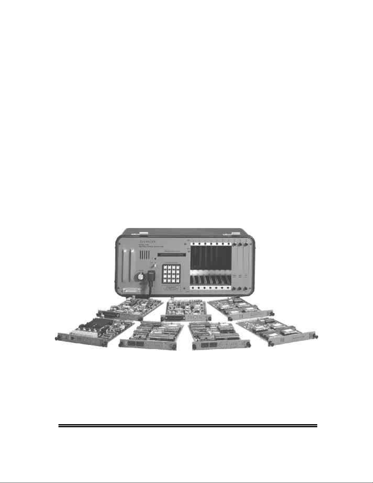
AM7
Central Office Simulator
Instruction Manual
A
meritec
CORPORATION
Page 2

AM7
Central Office Simulator
Instruction Manual
September 17, 1999
Technical Data Subject to
Change without Notice
For extra copies of this
manual, order Part
No. 18-0014
Page 3

Record of Revisions
00 September, 1986 Review copy.
01 January, 1987 Preliminary Issue. Incorporated Engineering comments.
A August, 1988 PCM Addendum
B September, 1993
SLC®96 Addendum
C July, 1997 Rewritten and Reformatted
D May 11, 1998 E&M Linecard SW2 Settings were revised (pg. 1-15).
D1 September 17, 1999 Added Dial Tone Generation specification
This Manual was produced on a Power Macintosh using MS Word 6.0 and Adobe Illustrator
6.0.1.
SLC®96 is a trademark of American Telephone & Telegraph.
September 17, 1999 0014-TPG.D1 1
ii
Page 4

AM7 User's Manual (18-0014) Table of Contents
Table of Contents
1. INTRODUCTION .............................................................................................1-1
1.1 AM7 User Manual Overview.....................................................................1-2
1.2 Physical Description................................................................................1-3
1.3 Front Panel..............................................................................................1-4
1.3.1 Fan Exhaust/Speaker Vents.............................................................1-4
1.3.2 RS-232 Connector............................................................................1-4
1.3.3 Audio Monitor Output/Volume Control..............................................1-5
1.3.4 Power Connection.............................................................................1-5
1.3.5 Power Switch and Power Indicator...................................................1-6
1.3.6 Parameter/Data Display and Shift Indicator..................................... 1-6
1.3.7 Program Keyboard............................................................................1-6
1.3.7.1 Primary Key Functions ...............................................................1-7
1.3.7.2 Secondary Key Functions...........................................................1-8
1.3.7.3 Terminal Keyboard Operation.................................................... 1-9
1.3.8 Interface Port Cards........................................................................1-10
1.3.8.1 Dual Line Analog Loop/Ground Start linecards........................1-12
1.3.8.2 Dual Line Analog E&M linecards..............................................1-13
1.3.8.3 Single Line PCM linecards.......................................................1-17
1.3.8.4 Single Line DLC linecards........................................................1-18
1.3.8.5 Tone Receiver Cards................................................................1-19
1.4 Accessories...........................................................................................1-20
1.4.1 Transit Case....................................................................................1-20
1.4.2 Rack Mounting Kit...........................................................................1-20
1.4.3 Spare Card Carrying Case..............................................................1-20
2. GETTING STARTED....................................................................................2-1
2.1 Unpacking................................................................................................2-1
2.2 Power.......................................................................................................2-1
2.3 Basic Operation.......................................................................................2-2
2.3.1 Loop/Ground Start Card Operation...................................................2-3
2.3.2 PCM Card Operation.........................................................................2-4
2.3.3 DLC Card Test..................................................................................2-6
0014-TOC.0190 July, 1997
iii
Page 5

Table of Contents (18-0014) AM7 User's Manual
3. SYSTEM SETUP AND PROGRAMMING....................................................3-1
3.1 System Parameters.................................................................................3-1
3.1.1 Clock/Calendar..................................................................................3-1
3.1.2 Automatic Printout.............................................................................3-1
3.1.3 Dial Tone Select................................................................................ 3-2
3.1.4 Dial Tone Level and Frequency........................................................3-2
3.1.5 Ringing Frequency............................................................................3-2
3.1.6 Ringing Sequences...........................................................................3-3
3.1.7 Ringback Sequences........................................................................3-3
3.1.8 Ringback Level and Frequency........................................................ 3-4
3.1.9 Line Busy Sequences.......................................................................3-4
3.1.10 Line Busy Level and Frequency.....................................................3-5
3.1.11 Reorder Sequences........................................................................3-5
3.1.12 Reorder Level and Frequency........................................................ 3-6
3.1.13 Tone Dialing Analyzer Report......................................................... 3-6
3.1.13.1 Low Tone Level ........................................................................3-7
3.1.13.2 High Tone Level........................................................................3-7
3.1.13.3 Twist Level................................................................................3-7
3.1.13.4 Frequency Offset......................................................................3-7
3.1.13.5 Tone ON/OFF Time..................................................................3-8
3.1.13.6 Tone Guard Time......................................................................3-8
3.1.13.7 Tone Dial Line Analysis............................................................3-8
3.1.13.8 Tone Dial All Digits Analysis.....................................................3-9
3.1.14 Dial Pulse Report............................................................................3-9
3.1.14.1 Pulse Speed..............................................................................3-9
3.1.14.2 Pulse Break...............................................................................3-9
3.1.14.3 Pulse Interdigit Time...............................................................3-10
3.1.14.4 Dial Pulse Line Analysis......................................................... 3-10
3.1.14.5 Dial Pulse All Digits Analysis.................................................. 3-10
3.1.15 Connection Loss...........................................................................3-10
3.1.16 Master Span..................................................................................3-10
3.1.17 Receiver Card Signaling Type......................................................3-11
3.1.18 RS-232C Port Configuration.........................................................3-11
3.1.19 Software Version...........................................................................3-11
July, 1997 0014-TOC.0190
iv
Page 6

AM7 User's Manual (18-0014) Table of Contents
3.2 Line Parameters.................................................................................... 3-12
3.2.1 Analog Card Line Parameters ........................................................3-12
3.2.1.1 Dial Tone Delay........................................................................3-12
3.2.1.2 Auto Code.................................................................................3-12
3.2.1.3 Confirming Tone....................................................................... 3-13
3.2.1.4 Hunt Group...............................................................................3-14
3.2.1.5 Answer Supervision..................................................................3-14
3.2.1.6 Dialing Code Group..................................................................3-14
3.2.1.7 Dialing Code Report.................................................................3-15
3.2.1.8 Call Progress Tones.................................................................3-15
3.2.1.9 Tone Dial (DTMF) and Dial Pulse Decode...............................3-15
3.2.1.10 Flash Time..............................................................................3-16
3.2.1.11 Disconnect Time.....................................................................3-16
3.2.1.12 Wink Time...............................................................................3-16
3.2.1.13 Call Activity Registers............................................................. 3-17
3.2.2 PCM (T1) Card Line Parameters....................................................3-18
3.2.2.1 Emulation..................................................................................3-19
3.2.2.2 Start Mode................................................................................3-19
3.2.2.3 Dial Tone Delay........................................................................3-20
3.2.2.4 Auto Code.................................................................................3-20
3.2.2.5 Confirming Tone....................................................................... 3-21
3.2.2.6 Hunt Group...............................................................................3-21
3.2.2.7 Answer Supervision..................................................................3-22
3.2.2.8 Dialing Code Group..................................................................3-22
3.2.2.9 Dialing Code Report.................................................................3-22
3.2.2.10 Call Progress Tones...............................................................3-23
3.2.2.11 Tone Dial and Dial Pulse Decode..........................................3-23
3.2.2.12 Tone Receiver Type Required...............................................3-23
3.2.2.13 Flash Time..............................................................................3-23
3.2.2.14 Disconnect Time.....................................................................3-24
3.2.2.15 Wink Time...............................................................................3-24
3.2.2.16 Call Activity Registers............................................................. 3-24
3.2.3 DLC (SLC®96) Card Line Parameters............................................3-26
3.2.3.1 Emulation..................................................................................3-30
3.2.3.2 Trunk Assignment Delay..........................................................3-30
3.2.3.3 Dial Tone Delay........................................................................3-31
0014-TOC.0190 July, 1997
v
Page 7

Table of Contents (18-0014) AM7 User's Manual
3.2.3.4 Auto Code.................................................................................3-31
3.2.3.5 Confirming Tone....................................................................... 3-32
3.2.3.6 Hunt Group...............................................................................3-32
3.2.3.7 Dialing Code Group..................................................................3-32
3.2.3.8 Dialing Code Report.................................................................3-33
3.2.3.9 Call Progress Tones.................................................................3-33
3.2.3.10 Tone Dial and Dial Pulse Decode..........................................3-33
3.2.3.11 Flash Time..............................................................................3-33
3.2.3.12 Disconnect Time.....................................................................3-34
3.2.3.13 Wink Time...............................................................................3-34
3.2.3.14 Timeslot Register....................................................................3-34
3.2.3.15 Call Activity Registers............................................................. 3-35
3.3 DTMF Dialing Analyzer Operation........................................................3-36
3.3.1 Tone Events....................................................................................3-36
3.3.1.1 Tone Event Identification..........................................................3-37
3.3.1.2 Frequency and Percent Deviation............................................3-37
3.3.1.3 Level..........................................................................................3-38
3.3.1.4 Twist..........................................................................................3-38
3.3.1.5 Event Timing.............................................................................3-38
3.4 Dialing Codes........................................................................................3-39
3.4.1 Dialing Code Programming.............................................................3-40
3.4.1.1 Expected Digit Field..................................................................3-40
3.4.1.2 Action Code Step Sequences ..................................................3-42
4. PROGRAMMING EXAMPLES AND TESTS...............................................4-1
4.1 Dialing Code Programming.....................................................................4-1
4.1.1 Analog Line Programming................................................................4-1
4.1.2 Multi-Frequency (MF) Programming.................................................4-1
4.2 Programming Examples..........................................................................4-2
4.2.1 PBX Station Calling a Test Tone Source..........................................4-4
4.2.2 Central Office Modem Switching......................................................4-5
4.2.3 Expected Digits in Excess of 12 Digits............................................. 4-7
4.3 Switching and Test Applications.............................................................4-8
4.3.1 Basic Dialing Test.............................................................................4-9
4.3.2 Autodial Modem Test......................................................................4-10
July, 1997 0014-TOC.0190
vi
Page 8

AM7 User's Manual (18-0014) Table of Contents
5. REPORTS.....................................................................................................5-1
5.1 Automatic Reports...................................................................................5-1
5.1.1 Power ON and Power OFF Report...................................................5-1
5.1.2 Data Readout Report........................................................................5-2
5.1.3 Dial Pulse Report.............................................................................. 5-4
5.1.4 Tone Dial Report...............................................................................5-4
5.1.5 Dialing Code Error Report.................................................................5-5
5.2 Special Function Reports........................................................................5-5
5.2.1 Special Function 1 Report.................................................................5-5
5.2.2 Special Function 2 Report.................................................................5-6
5.2.3 Special Function 3 Report.................................................................5-7
5.2.4 Special Function 4.............................................................................5-8
5.2.5 Special Function 5.............................................................................5-8
5.2.6 Special Function 6.............................................................................5-8
5.2.7 Special Function 7.............................................................................5-8
5.2.8 Special Function 8 Report.................................................................5-9
5.2.9 Special Function 9 Report...............................................................5-10
6. CHAINING AND REMOTE CONTROL OPERATION.................................6-1
6.1 Chaining...................................................................................................6-1
6.2 Remote Control Operation......................................................................6-2
6.2.1 RS-232C Interface............................................................................6-2
6.2.2 Terminal Operation...........................................................................6-3
6.2.2.1 System Menu..............................................................................6-4
6.2.2.2 Line Menu................................................................................... 6-5
6.2.2.3 Dialing Menu...............................................................................6-5
6.2.3 Special Functions..............................................................................6-6
6.2.4 Help Displays....................................................................................6-7
7. TECHNICAL SPECIFICATIONS..................................................................7-1
7.1 System.....................................................................................................7-1
7.1.1 Capacity.............................................................................................7-1
7.1.2 Simultaneous Calls...........................................................................7-1
7.1.3 Busy Hour Call Volume..................................................................... 7-1
7.1.4 Chaining............................................................................................7-1
7.1.5 Signaling Systems.............................................................................7-2
0014-TOC.0190 July, 1997
vii
Page 9

Table of Contents (18-0014) AM7 User's Manual
7.2 Detectors .................................................................................................7-2
7.2.1 Analog Loop/Ground Start................................................................7-2
7.2.2 Analog E&M......................................................................................7-2
7.2.3 T1/SLC®96.........................................................................................7-2
7.3 Digit Decoders.........................................................................................7-2
7.3.1 DTMF.................................................................................................7-2
7.3.2 MF(R1)..............................................................................................7-3
7.3.3 Dial Pulse.......................................................................................... 7-3
7.4 Digit Analyzer...........................................................................................7-3
7.4.1 Tone Dialing......................................................................................7-3
7.4.2 Pulse Dialing.....................................................................................7-3
7.5 Tone Generators.....................................................................................7-4
7.5.1 Call Progress Tones..........................................................................7-4
7.5.2 Confirming Tones..............................................................................7-5
7.5.3 SIT Tones.......................................................................................... 7-5
7.6 Signal/Power Sources.............................................................................7-5
7.6.1 Loop Voltage (2W Analog)................................................................7-5
7.6.2 Ring Generator..................................................................................7-5
7.7 Miscellaneous..........................................................................................7-6
7.7.1 Frequency Response........................................................................7-6
7.7.2 Connection Loss ...............................................................................7-6
7.7.3 T1/SLC®96 Interfaces .......................................................................7-6
7.7.4 User Interface....................................................................................7-6
7.7.5 RS-232C/V.24 Port...........................................................................7-6
7.7.6 Audio Monitor....................................................................................7-6
7.7.7 Non-Volatile Memory.........................................................................7-6
7.8 Power.......................................................................................................7-6
7.9 Dimensions..............................................................................................7-7
8. WARRANTY, CALIBRATION, AND SERVICE...........................................8-1
8.1 Warranty.................................................................................................. 8-1
8.2 Service Policy..........................................................................................8-1
8.3 Calibration Policy..................................................................................... 8-1
8.4 Return of Unit...........................................................................................8-2
9. GLOSSARY..................................................................................................9-1
July, 1997 0014-TOC.0190
viii
Page 10

AM7 User's Manual (18-0014) Table of Contents
List of Figures
Figure 1-1. AM7 Central Office Simulator........................................................1-1
Figure 1-2. AM7 Front Panel............................................................................1-4
Figure 1-3. RS-232C Interface .........................................................................1-5
Figure 1-4. Program Keyboard.........................................................................1-6
Figure 1-5. Terminal Keyboard Connection (ASCII)........................................ 1-9
Figure 1-6. Terminal Keyboard Connection (Remote)...................................1-10
Figure 1-7. Loop/Ground Start Linecard (28-0055)........................................1-11
Figure 1-8. E&M Linecard...............................................................................1-11
Figure 1-9. PCM Linecard...............................................................................1-11
Figure 1-10. DLC Linecard................................................................................1-11
Figure 1-11. Tone Receiver..............................................................................1-11
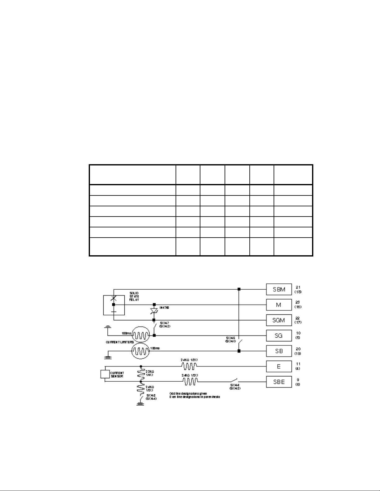
Figure 1-12. Loop/Ground Start DIP Switches................................................. 1-13
Figure 1-13. E&M Cable...................................................................................1-14
Figure 1-14. E&M Type 5 Cable.......................................................................1-14
Figure 1-15. E&M Linecard DIP Switch Locations...........................................1-15
Figure 1-16. Dial Pulse and DTMF E&M Line Interface Port Card..................1-15
Figure 1-17. Dial Pulse and MF E&M Interface Port Card...............................1-16
Figure 1-18. T1 Line Interface..........................................................................1-17
Figure 1-19. PCM Linecard DIP Switch Locations...........................................1-17
Figure 1-20. Tone Receiver Card DIP Switch..................................................1-20
Figure 2-1. Loop/Ground Start Card Operation................................................2-3
Figure 2-2. PCM Card Operation......................................................................2-4
Figure 2-3. DLC Card Test...............................................................................2-6
Figure 3-1. Dialing Code Worksheet..............................................................3-40
Figure 4-1. Dialing Code Worksheet................................................................4-3
Figure 4-2. PBX Station Calling a Test Tone Source.......................................4-4
Figure 4-3. Central Office Modem Switching ...................................................4-5
Figure 4-4. Expected Dialing Code Longer than 12 Digits...............................4-7
Figure 4-5. Basic Dialing Test...........................................................................4-9
Figure 4-6. Autodial Modem Test...................................................................4-11
0014-TOC.0190 July, 1997
ix
Page 11

Table of Contents (18-0014) AM7 User's Manual
Figure 5-1. Power ON and Power OFF Report................................................5-1
Figure 5-2. Data Readout Report.....................................................................5-2
Figure 5-3. Data Readout Report (T1 Span 1).................................................5-3
Figure 5-4. Dial Pulse Report...........................................................................5-4
Figure 5-5. Tone Dial Report............................................................................5-4
Figure 5-6. Dialing Code Error Report..............................................................5-5
Figure 5-7. Special Function 1 Report..............................................................5-5
Figure 5-8. Special Function 2 Report..............................................................5-7
Figure 5-9. Special Function 3 Report..............................................................5-7
Figure 5-10. Special Function 8 Report..............................................................5-9
Figure 5-11. Special Function 9 Report............................................................5-10
Figure 6-1. Chaining of AM7 Units..................................................................6-1
Figure 6-2. Universal Printer Cable..................................................................6-2
Figure 6-3. AM7/Terminal Key Equivalents......................................................6-3
Figure 6-4. System Menu .................................................................................6-4
Figure 6-5. Line Menu.......................................................................................6-5
Figure 6-6. Dialing Code Menu.........................................................................6-5
July, 1997 0014-TOC.0190
x
Page 12

AM7 User's Manual (18-0014) Table of Contents
List of Tables
Table 1-1. Primary Key Functions....................................................................1-7
Table 1-2. Secondary Key Functions...............................................................1-8
Table 1-3. Terminal Keyboard Definitions......................................................1-10
Table 1-4. Loop- and Ground-Start Linecard SW1 Settings..........................1-13
Table 1-5. Loop- and Ground-Start Linecard SW2 Settings..........................1-13
Table 1-6. E&M Linecard SW2 Settings.........................................................1-15
Table 1-7. E&M Linecard SW3 Settings.........................................................1-16
Table 1-8. E&M Linecard SW4 Settings.........................................................1-17
Table 1-9. PCM Cable Length/Type Selection...............................................1-18
Table 1-10. PCM Linecard Slot/Span Selection...............................................1-18
Table 1-11. Tone Receiver Card SW1 Settings...............................................1-20
Table 3-1. Confirming "Step Sequence" Tones .............................................3-13
Table 3-2. Call Progress Tone Levels............................................................3-15
Table 3-3. PCM Card Span Data Registers...................................................3-19
Table 3-4. DLC Card Mode & Span Setting...................................................3-27
Table 3-5. SLC®96 Alarm Character Meaning ...............................................3-29
Table 3-6. DLC Card Span Data Registers....................................................3-30
Table 3-7. Expected Digit Field Definitions....................................................3-41
Table 3-8. MF Expected Digit Field Definitions..............................................3-41
Table 3-9. Action Code Definitions.................................................................3-42
Table 4-1. KP/ST Digit Tone Pairs...................................................................4-2
Table 6-1. Terminal Keyboard Special Functions............................................6-6
0014-TOC.0190 July, 1997
xi
Page 13

Table of Contents (18-0014) AM7 User's Manual
July, 1997 0014-TOC.0190
xii
Page 14
AM7 User’s Manual (18-0014) Introduction
1. INTRODUCTION
MODEL AM7
CENTRAL OFFICE SIMULATOR
ON
PWR
(PULL)
CAUTION
85-120 VAC
ONLY
VOLUME
AUDIO
MONITOR
OUTPUT
RS232
PARAMETER/DATA DISPLAY
PROGRAM KEYBOARD
SEL
32
1
ESC
* ( ) # ( ) SHIFT
DO NOT REMOVE OR INSERT
BOARDS WITH POWER ON
ETR
SPCL
COPY
FLASH
0
BLANKNEG (-)
* CAUTION *
A
i
654
ETR
B
ETR
987
C
D
SHIFT
5
7
3
1
LINE
4
2
PCM
DLC
DLC
SEL
A
B
A
B
ACTIVE
DL
LT
NA
MON.
LINE
28-0069-DLC
1.544
96
96
SEL
SEL
A
S
S
S
S
I
I
B
G
G
A
B
B
R
R
I
I
B
T
T
S
S
DATA
ACTIVE
DL
E
E
R
R
LT
R
R
O
O
NA
R
R
MON.
MON.
S
S
R
R
S
S
R
R
LINE
LINE
26-0069
28-0069-DLC
2
1
9
6
8
10
LOOP/GND
LOOP/GND
PCM
1.544
START
START
SEL
HK
HK
SEL
SEL
1
1
2
2
3
3
4
DATA
5
6
7
8
S
R
S
R
3
HK
HK
4
5
SEL
SEL
6
7
8
MON.
S
R
S
R
LINE
28-0055
28-0055
26-0069
4SLOT
5
15
13
11
16
14
12
LOOP/GND
LOOP/GND
START
START
HK
HK
SEL
SEL
HK
HK
SEL
SEL
28-0055
28-0055
7
6
19
17
20
18
TONE
TONE
RCVRS
RCVRS
1
1
2
2
A
A
3
3
4
4
1
1
2
2
B
B
3
3
4
4
10
9
8
Figure 1-1. AM7 Central Office Simulator
The Ameritec AM7 Central Office Simulator is a simulator of Central Office
switches, PABX switches, or the Public Switched Telephone Network (PSTN).
The AM7 is user-programmable, allowing realistic testing when an actual switch
is not available. It is a self-contained, compact, lightweight unit which is easily
hand carried, or can be rack mounted for laboratory use.
The AM7 mainframe is a miniature, high performance, non-blocking digital
switch. It is capable of switching up to 48,000 calls per hour, and has 10 option
card slots for installation of plug-in interfaces. Interface options include:
• 1 - 10 Analog Loop/Ground Start linecards
• 1 - 10 Dual Line Analog E & M linecards
• 1 - 4 Single Line T1 PCM linecards and/or Single Line DLC linecards
• 1 - 7 Tone Receivers for decoding MF and DTMF digits for use with PCM or
DLC interfaces
0014-S01.B_135 May 11, 1998
1-1
Page 15

Introduction (18-0014) AM7 User's Manual
The AM7 is easily configured to simulate a variety of CO or PABX switches.
This allows testing to be performed in development or manufacturing
environments without having to connect lines to a live switch.
• The Analog line interface options for the AM7 make it perfect for testing of
Customer Premises Equipment (CPE), particularly in development,
manufacturing, and repair areas.
• The PCM line interface option allows testing of CPE or switching equipment
with T1 interfaces, and when used in combination with Analog linecards,
allows the AM7 to simulate the subscriber and trunk functions of a switch.
• The DLC option allows the AM7 to fully simulate a COT, making the AM7
perfect for installation testing of SLC®96 Remote Terminals (RTs).
The portability of the AM7 allows use in the field to test or install CPE or other
equipment. The ability to remote control the AM7 via a built in RS-232 port
makes it suitable for automated test applications in the laboratory.
1.1 AM7 User Manual Overview
The AM7 is a very versatile unit that is used in different environments
throughout the world. As a result, no manual could be written to exactly match
your testing requirements. Instead, a Getting Started Section with generalized
applications has been written. These applications include step-by-step
instructions that you can modify to meet your testing needs. The following is a
summary of the manual's contents by section.
Table of Contents contains a detailed Table of Contents, List of Figures, and
List of Tables.
Section 1, Introduction, provides an overview of the basic functionality of the
unit. It shows the location and layout of the front panel and describes its
components. It also discusses cabling, power, options, and accessories.
Section 2, Getting Started, provides information regarding Unpacking, Power
On/Off, Memory Backup, and AM7 operation.
July, 1997 0014-S01.B_135
1-2
Page 16

AM7 User’s Manual (18-0014) Introduction
Section 3, System Setup and Programming, introduces System and Line
parameters, Dialing Analyzer parameters, and Action Codes.
Section 4, Programming Examples and Tests, provides examples of AM7
Dialing Code programming, and various switching and test applications that may
be accomplished by means of the programming.
Section 5, Reports, lists and describes both the Automatic Unit Data Register
and User Requested reports, including report parameters and available options.
Section 6, Remote Control/Chaining, describes the method of remotely
controlling the operation and printing of reports from the AM7. It also provides
information regarding the "chaining" together of multiple AM7 units.
Section 7, Technical Specifications, is to be consulted for an overview of the
AM7's capabilities and operating parameters.
Section 8, Warranty and Service, provides warranty, calibration, service, and
repair information for the AM7.
Section 9, Glossary, contains a list of acronyms or abbreviations used in this
manual.
Section 10, Index, provides an alphabetical listing of all topics.
In this manual slashed zeroes (ø) are used to distinguish the number zero from
the letter "O" when entering RS-232 commands or representing displayed values.
Elsewhere slashed zeroes are only used if there's a chance confusion would result
if they weren't used.
1.2 Physical Description
The AM7 is furnished in a portable bench top case with accessory brackets for
rack mount applications. The portable AM7 consists of a rugged fiberglass
carrying case, containing a frame assembly that houses the system's printed
circuit boards and interface cards. A front panel is attached to the frame
assembly to provide the user interface. The rear of the unit provides no controls
or access.
0014-S01.B_135 May 11, 1998
1-3
Page 17
Introduction (18-0014) AM7 User's Manual
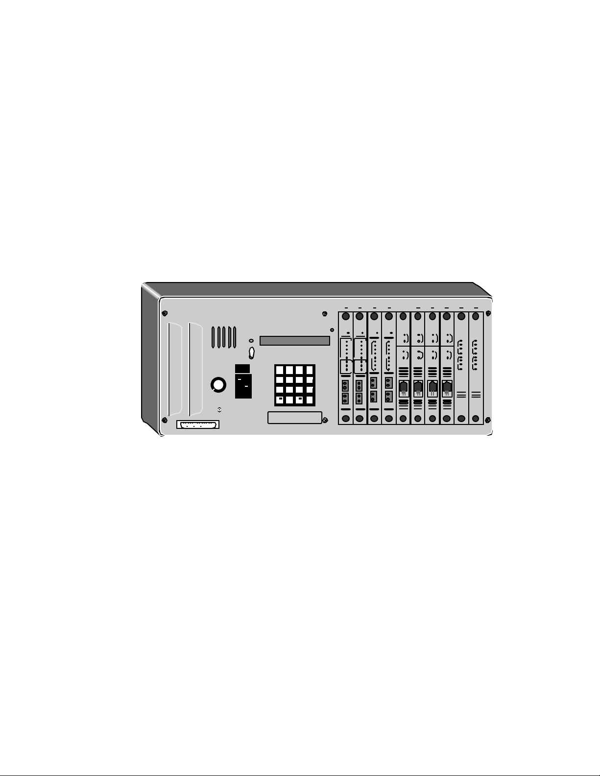
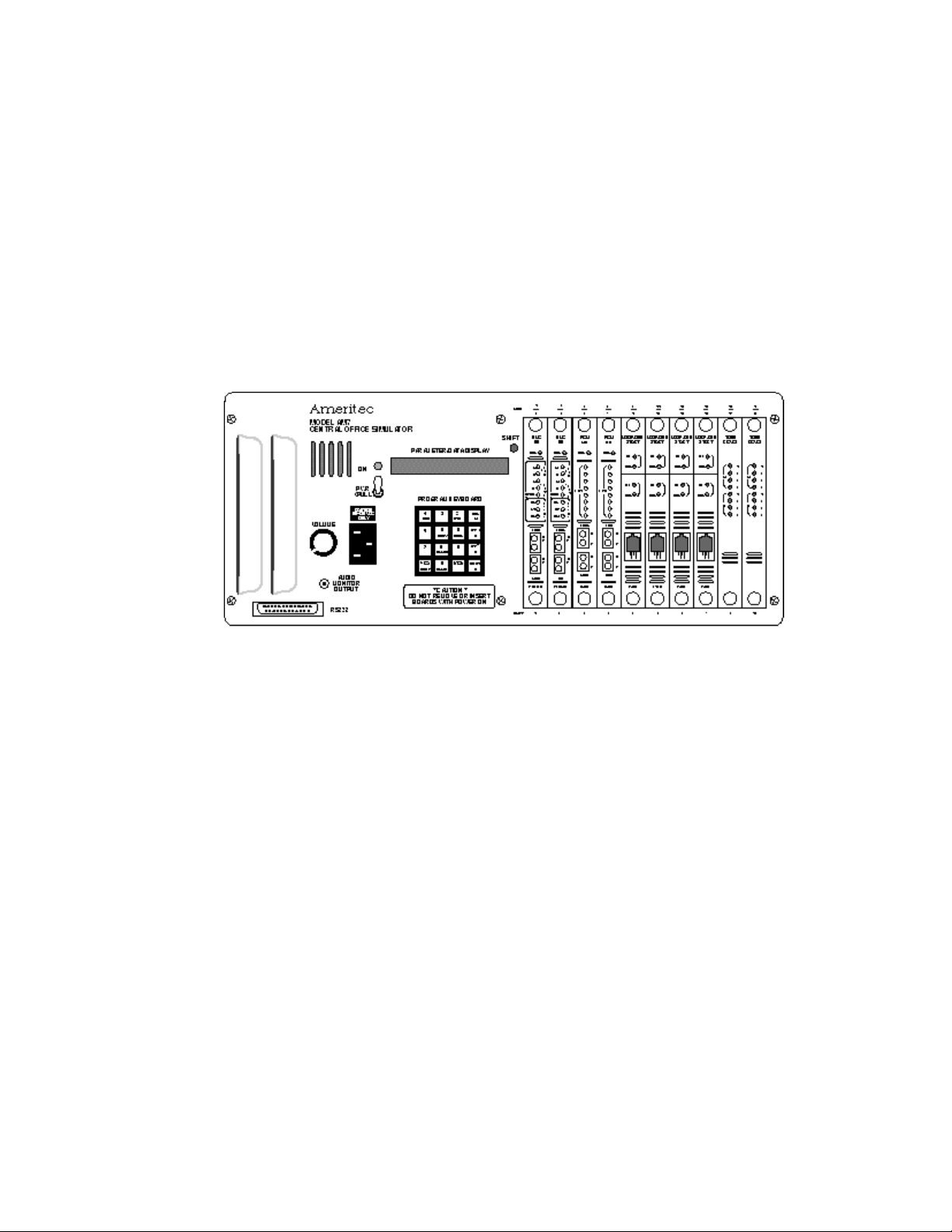
Figure 1-2. AM7 Front Panel
1.3 Front Panel
The front panel of the AM7 provides all the controls and connectors for the unit
and hosts an assortment of up to ten line cards.
1.3.1 Fan Exhaust/Speaker Vents
Two air vents required for the internal cooling fan are located on the left edge of
the AM7 front panel. Five slotted vents required for the AM7 Speaker appear
immediately to the right of the air vents.
1.3.2 RS-232 Connector
Each AM7 is equipped with an EIA RS-232C digital interface located in the
lower left corner of the front panel. It is compatible with most serial ASCII
printers, CRT's, PC's, and modems.
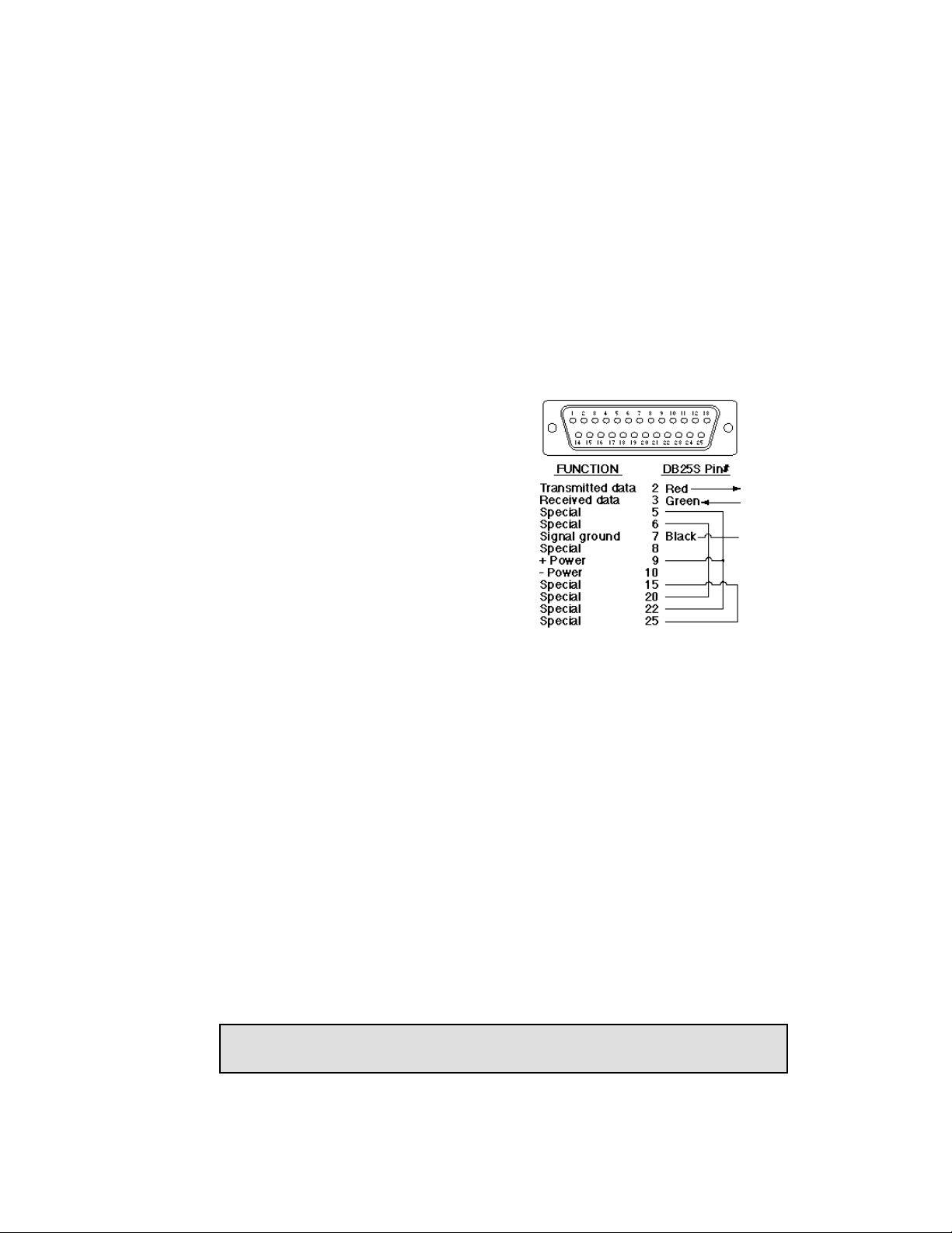
Certain pins in the DB-25 male connector must be tied together for proper system
operation. If a terminal is directly connected to the AM7, the Ameritec Universal
Printer Cable, or equivalent, is required.
July, 1997 0014-S01.B_135
1-4
Page 18
AM7 User’s Manual (18-0014) Introduction
The jumpers must always be
installed between the Special
function pins, due to proprietary
communications techniques that
allow the AM7 units to be "chained".
The ASCII device connected to the
AM7 only deals with pins 2, 3, and 7
and is not involved with the Special
function pins. Please see the Remote
Control Operation section of this
user's manual for details regarding
RS-232C operation.
Figure 1-3. RS-232C Interface
1.3.3 Audio Monitor Output/Volume Control
The Audio Monitor Output and Volume Control are located just above the RS232 connector on the front panel. The Volume Control controls the Audio
Monitor Output volume for any of the lines that can be installed in the AM7.
The Audio Monitor Output jack (industry standard TRS bantam) is automatically
connected to the line selected from the keypad. The output is suited for
connection to a Transmission Test Set for noise, level, and frequency
measurements of the selected line's tones.
1.3.4 Power Connection
The AM7 is powered from an AC source of 108-125VAC, 50/60Hz, or 210230VAC, 50/60Hz, 50W max. The Power Connection consists of a standard Vtype connector and is located just to the right of the Volume Control. The power
supply automatically adjusts the line voltage and frequency.
Note: The non-volatile memory is maintained by a lithium battery with a
longevity of about six years continuous operation.
0014-S01.B_135 May 11, 1998
1-5
Page 19

Introduction (18-0014) AM7 User's Manual
1.3.5 Power Switch and Power Indicator
The Power Switch is a knob-type on/off switch that must be pulled out during
switching. It is located just above the Power Connection. An LED, located
immediately above the Power Switch, glows green when power is applied to the
AM7 and the unit is switched on.
1.3.6 Parameter/Data Display and Shift Indicator
The Parameter/Data Display is a 16-digit alpha-numeric LED display, presenting
red characters on a black background. The AM7 has a number of parameters
unique to the overall system and offers a wide variety of parameters that may be
applied to each individual line. The Parameter/Data Display allows you to view
the values in each data register, permitting changes to be made in the operating
parameters via the Program Keyboard. Each parameter value is discussed in
greater detail in the section on Getting Started.
A value containing a decimal point is displayed without one (35.1 is displayed as
351, for example).
An LED is located just above the upper right-hand corner of the Parameter/Data
Display. The LED glows red when the SHIFT key on the Program Keyboard is
pressed. The LED goes dark only after the next key is pressed.
1.3.7 Program Keyboard
The Program Keyboard is used to program and set
up the AM7. It is a multi-function, two color, 16-
1
ESC
ETR
key keypad, that initiates primary (black type) and
secondary (red type) functions. Secondary
COPY
functions are accessed by pressing the SHIFT key,
then pressing the required secondary function key.
They can also be performed through a terminal
keyboard. The keypad and terminal keyboard
commands are provided below.
July, 1997 0014-S01.B_135
1-6
Figure 1-4. Program Keyboard
FLASH
* ( ) # ( )
0
BLANKNEG (-)
32
654
SPCL
987
SEL
A
ETR
B
ETR
C
SHIFT
D
Page 20

AM7 User’s Manual (18-0014) Introduction
1.3.7.1 Primary Key Functions
The primary key (black type) functions are listed below.
Table 1-1. Primary Key Functions
Front
Panel
Key(s)
1 thru 0 Number keys - Enter digits 1 thru 0
SEL Select key - Selects system, line, and dial code parameters, which may
be altered by changing the data in the displayed registers
SEL + 000 + ETRê = System Parameters
SEL + 001 thru 020 + ETRê = Analog Line Parameters
SEL + 100 thru 400 + ETRê = PCM Line Parameters
SEL + 0A1 thru 4D8 + ETRê = Dialing Code Parameters
ETRê Enter-B key - Enters data after it has been typed in using the number/
symbol keys, or enters a parameter and steps to the next one
ETRè Enter-C key - Enters data after it has been typed in using the number/
symbol keys, or enters a parameter and steps to the next line at the
same program parameter
*( [ ) Represents either a KP digit (MF receiver enabler) for MF operations or
an asterisk for DTMF operations. Entered by pressing the *( [ ) key.
The digit is represented by an asterisk on the display
Description
#( ] ) Represents either an ST digit (MF receiver disabler) for MF operations
or a pound sign for DTMF operations. Entered by pressing the #( ] )
key. The digit is represented by a pound sign on the display
SHIFT Shift key - Enables secondary function keys to operate
0014-S01.B_135 May 11, 1998
1-7
Page 21
Introduction (18-0014) AM7 User's Manual
1.3.7.2 Secondary Key Functions
Secondary key (red type) functions are enabled via the Shift key.
Table 1-2. Secondary Key Functions
Front
Panel
Key(s)
ESC Escape key - Escapes present operation or discards the present entry
ETRé Enter-3 key - Enters data, and back-steps to the previous parameter
A to D A thru D keys - Enter their respective letters
COPY Copy key - Copys programmed data from one line to another line or all
lines
within
the analog lines, or copies
between spans
SPCL Special key - Provides special secondary functions
SHIFT + SPCL + 1 + ETRê = Print parameters associated with the
selected area (System, Line, or Dialing Code
SHIFT + SPCL + 2 + ETRê = Print all parameters and data registers
SHIFT + SPCL + 3 + ETRê = Print data registers
SHIFT + SPCL + 4 + ETRê = Reset all data registers
Description
within
DTMF
MF
A ST3P
B STP
C ST2P
D - -
a particular span, not
SHIFT + SPCL + 5 + ETRê = Reset the selected line's (001-020, 101124, 201-224, 301-324, 401-424) data registers
SHIFT + SPCL + 6 + ETRê = Stores up to 4 System, Line, and Dialing
Code parameter scenarios for later recall
SHIFT + SPCL + 7 + ETRê = Recalls up to 4 previously stored System,
Line, and Dialing Code parameter scenarios from memory
July, 1997 0014-S01.B_135
1-8
Page 22
AM7 User’s Manual (18-0014) Introduction
Front Panel
Key(s)
SPCL SHIFT + SPCL + 8 + ETRê = Print Dialing Codes for all
and PCM cards
SHIFT + SPCL + 9 + ETRê = Print data for selected analog line or
selected PCM card
(See Section 5, Reports, for the detailed operation of SPCL keys)
FLASH Flash key - Inserts a flash function into a dial number sequence to
expect a momentary On-Hook signal. The Flash function is denoted
by the letter F in the field of the dialed number
NEG (-) Negative key - Makes a value negative, and is used to program a
DTMF or MF twist limit. It is also used to enter a “don’t care” digit in
the dial code, expected digits field
BLANK Blank key - inserts a blank digit (space)
Description
1.3.7.3 Terminal Keyboard Operation
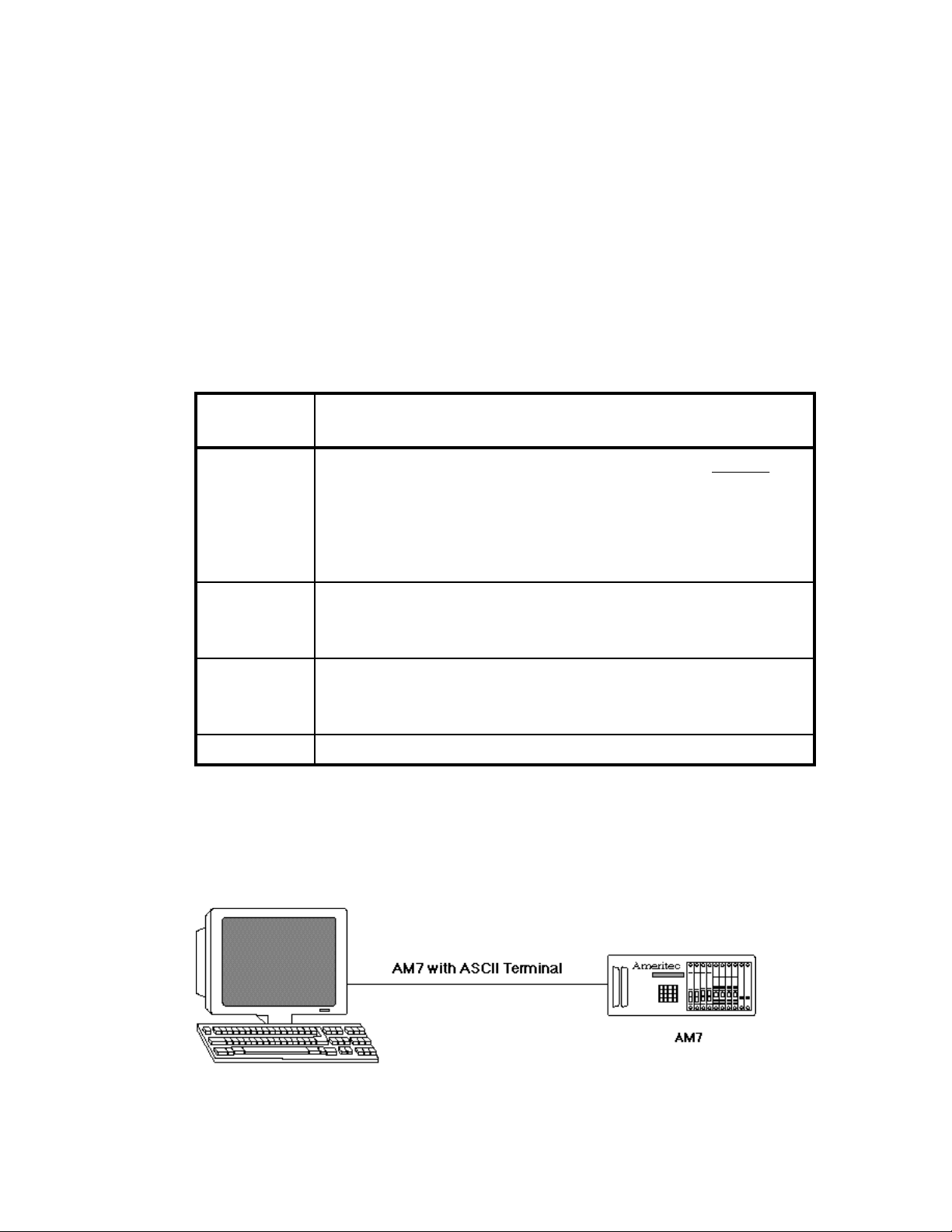
Operation of the AM7 through an ASCII terminal keyboard is similar to normal
operation through the keypad at the front panel. Examples of connecting an
AM7 to an ASCII terminal are shown in the following figures.
installed
lines
Figure 1-5. Terminal Keyboard Connection (ASCII)
0014-S01.B_135 May 11, 1998
1-9
Page 23
Introduction (18-0014) AM7 User's Manual
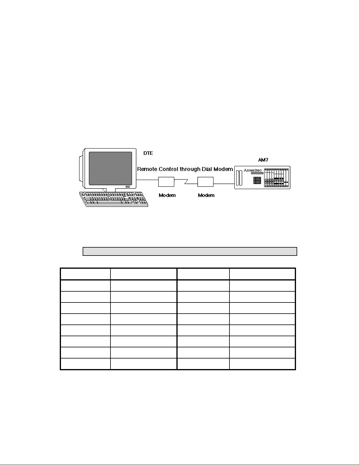
Figure 1-6. Terminal Keyboard Connection (Remote)
The terminal keyboard keys are used to access data registers in order to set AM7
operating parameters. There are exceptions to the similarities of the keyboard
and the keypad, and these are provided below.
CAUTION: Set and keep the keyboard in Caps Lock (Alpha Lock).
Table 1-3. Terminal Keyboard Definitions
Keypad Key Keyboard Equivalent Keypad Key Keyboard Equivalent
0 to 9, * and # 0 to 9, * and # Select A
Enter-B B or Return key Enter-C C or Line-Feed key
Enter-3 D3 Shift D
Escape D1 or E Copy D5
Special (SPCL) D6 Flash D8 or F
Negative (NEG) D* or - Blank D0 or Space key
A DA B DB
C DC D DD
July, 1997 0014-S01.B_135
1-10
Page 24
AM7 User’s Manual (18-0014) Introduction
1.3.8 Interface Port Cards
The AM7 is capable of housing from 1 to 10 of the following interface port
cards. Various mixes of options are possible, up to the 10 slot maximum:
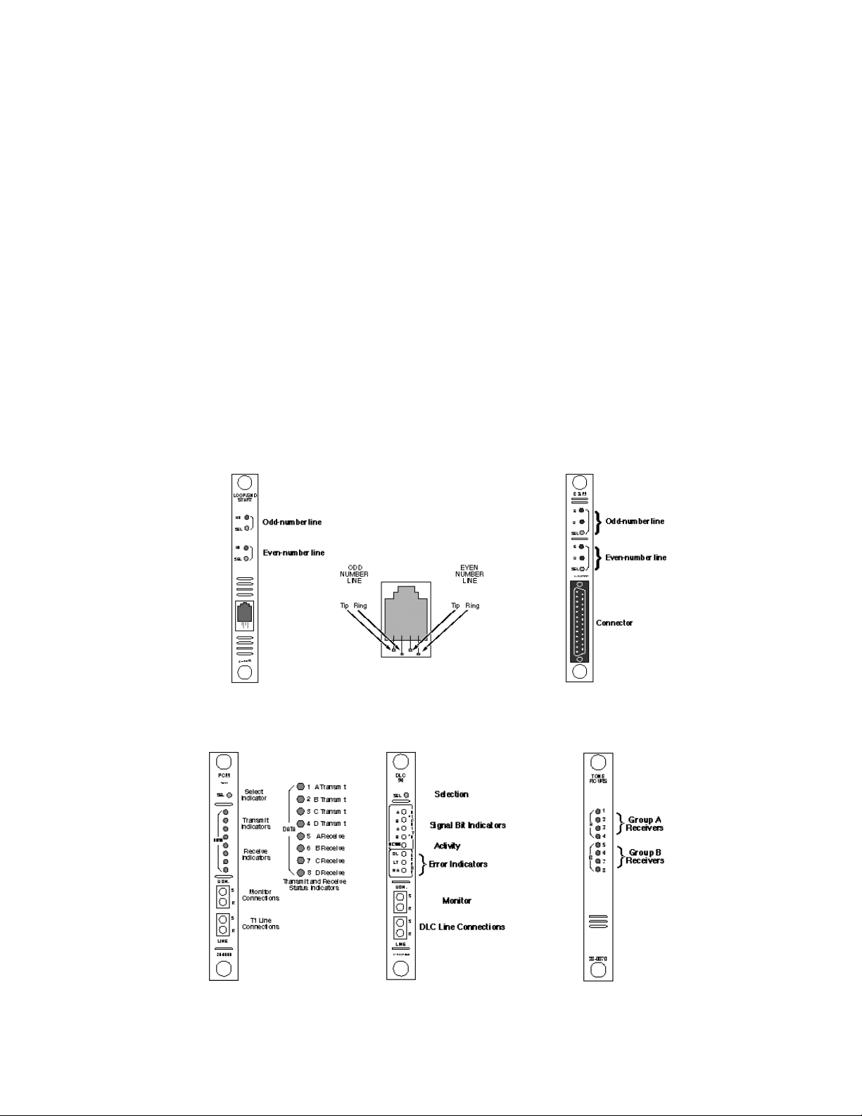
• Dual Line Analog Loop/Ground Start linecards Up to 10 cards
• Dual Line Analog E&M linecards Up to 10 cards
Figure 1-7. Loop/Ground Start Linecard (28-0055)
Figure 1-8. E&M Linecard
(28-0059 TT/28-0055 MF)
• Single Line T1 PCM and/or DLC linecards Up to 4 cards
• Tone Receiver Cards Up to 7 cards
Figure 1-9. PCM Linecard
(28-0069)
0014-S01.B_135 May 11, 1998
Figure 1-10. DLC Linecard
(28-0069-DLC)
1-11
Figure 1-11. Tone Receiver
(28-0070)
Page 25
Introduction (18-0014) AM7 User's Manual
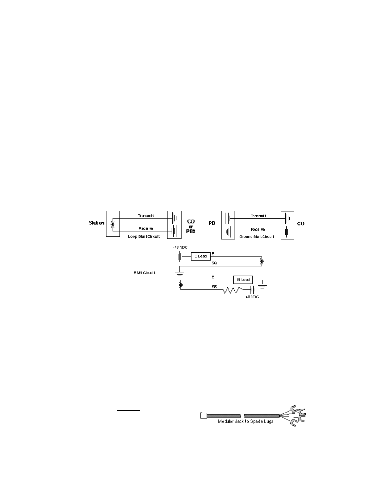
The AM7 Loop/Ground Start line 2-wire analog interface provides two
independent lines. Each line can originate and/or receive calls. The 2 and 4-wire
E&M line interface provides 2 independent lines. Each line can originate and/or
receive calls. The 4-wire T1 line interface (PCM) provides a send pair and receive
pair of contacts. It is capable of Loop/Ground Start, and E&M interface
emulation. The DLC card provides for the testing of SLC®96 equipment.
The types of cables used for the Interface Port Cards vary from card to card.
Cables are illustrated, along with their pin assignments. Each of the Interface Port
Cards is provided with a DIP switch(s) for the selection of Card Slot Numbers and
in some cases, particular card features.
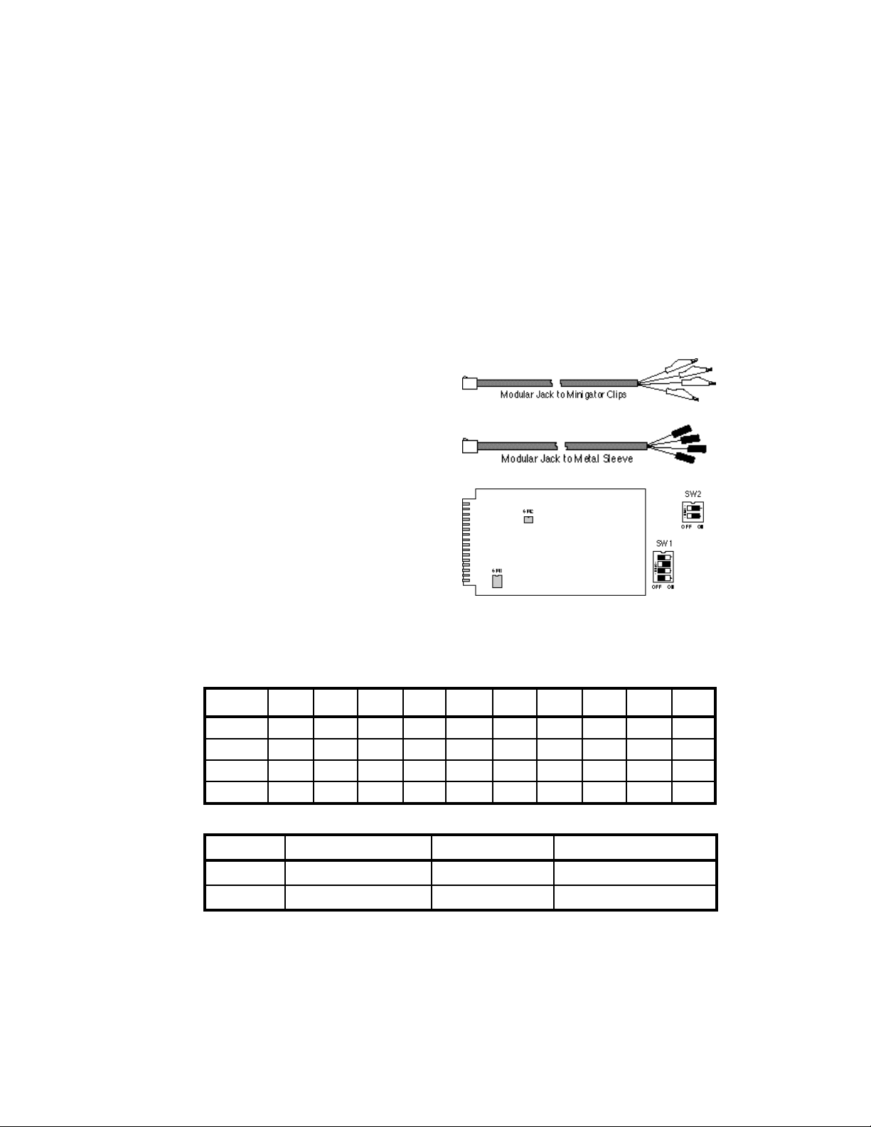
1.3.8.1 Dual Line Analog Loop/Ground Start linecards
The Loop/Ground Start linecard is a two-wire analog interface that provides two
independent lines, both capable of originating and receiving calls. One line is
assigned an odd number, the other an even number. Each card has two sets of
LED indicators, the top set for odd-numbered lines, the bottom set for evennumbered lines. A modular connector similar to that found on standard
telephone handsets is located on the
front of the card and can support three
different types of line cables.
July, 1997 0014-S01.B_135
1-12
P/N 48-0004
Page 26
AM7 User’s Manual (18-0014) Introduction
Slot01Slot02Slot03Slot04Slot05Slot06Slot07Slot08Slot09Slot
The Loop/Ground Start linecard
contains 2 DIP switches, SW1 and
SW2. SW1 is used to select the
P/N 48-0005
interface port card slot number. The
AM7 can accept up to 10 interface
port cards. Each card is identified
P/N 48-0006
from the address selected on this
switch. If two cards are set to the
same address, the AM7 will not
operate properly. The default settings
depend on the card slot assignment.
The SW2 selections indicate either
loop start or ground start operation
Figure 1-12. Loop/Ground Start DIP Switches
for each of the two lines on that interface port card. The default setting is for
Ground Start (both switches in the off position).
Table 1-4.Loop- and Ground-Start Linecard SW1 Settings
Switch
1 On Off On Off On Off On Off On Off
2 Off On On Off Off On On Off Off On
3 Off Off Off On On On On Off Off Off
4 Off Off Off Off Off Off Off On On On
10
Table 1-5. Loop- and Ground-Start Linecard SW2 Settings
Switch Function On Position Off Position
1 Odd-number line Loop Start Ground Start
2 Even-number line Loop Start Ground Start
0014-S01.B_135 May 11, 1998
1-13
Page 27
Introduction (18-0014) AM7 User's Manual
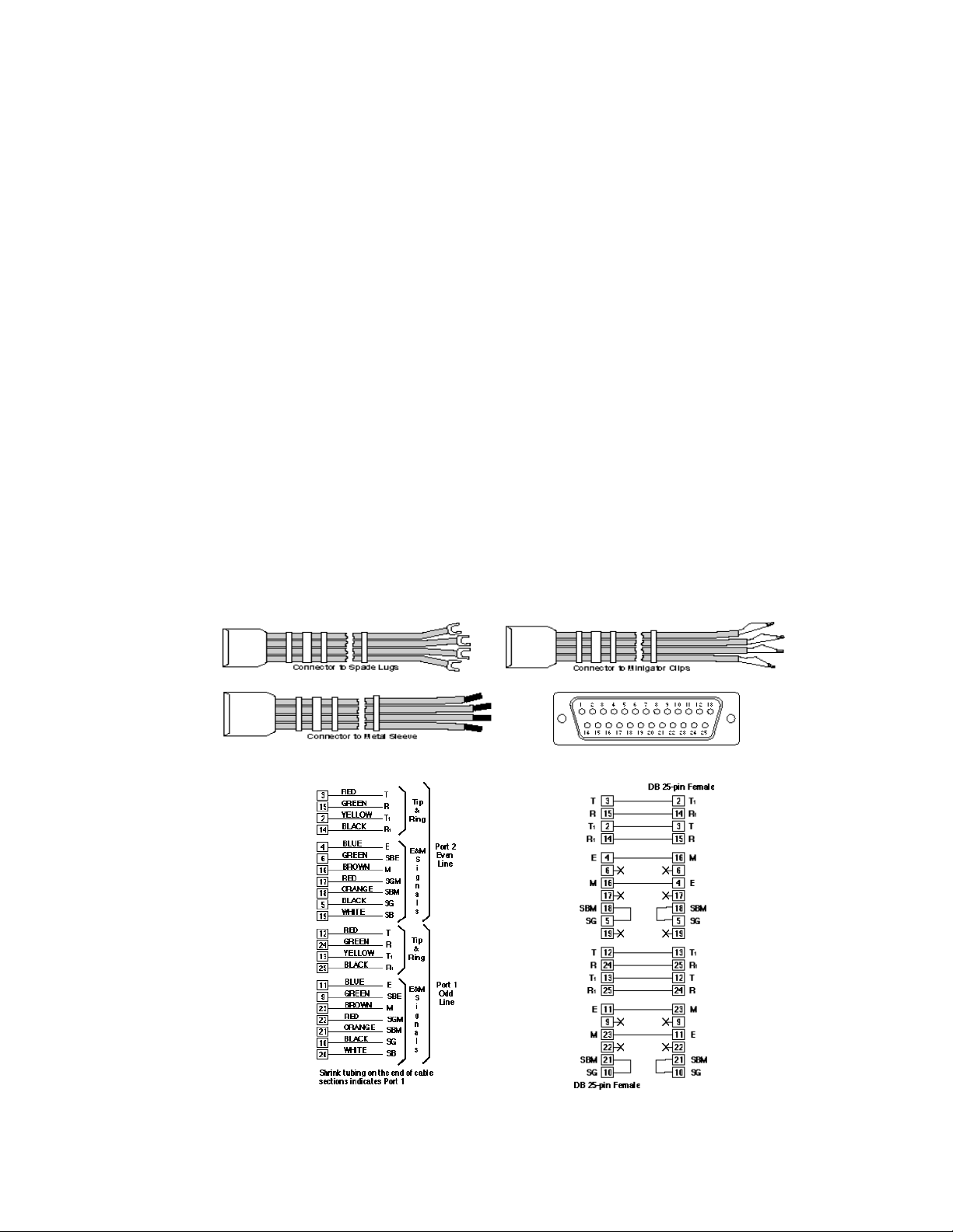
1.3.8.2 Dual Line Analog E&M linecards
There are two types of E&M linecards; one for decoding Dial Pulse and/or
DTMF digits (P/N 28-0059 TT) and one for decoding Dial Pulse and/or MF(R1)
digits (P/N 28-0059 MF). The two- and four-wire E&M linecard provides two
independent lines, both capable of originating and receiving calls. One line is
assigned an odd number, the other an even number. Each card has two sets of
LED indicators, the top set for odd-numbered lines, the bottom set for evennumbered lines. A 25-pin, D sub-miniature connector is located on the front of
the card and can support three different types of line cables. Two types of E&M
Interface cables are available, a regular 25 pin, D Sub-miniature connector, and
P/N 48-0075 P/N 48-0076
P/N 48-0077
an Inter-AM7 dual 7 E/M cable for an E&M Type 5 Interface.
Figure 1-13. E&M Cable
July, 1997 0014-S01.B_135
1-14
Figure 1-14. E&M Type 5 Cable
Page 28
AM7 User’s Manual (18-0014) Introduction
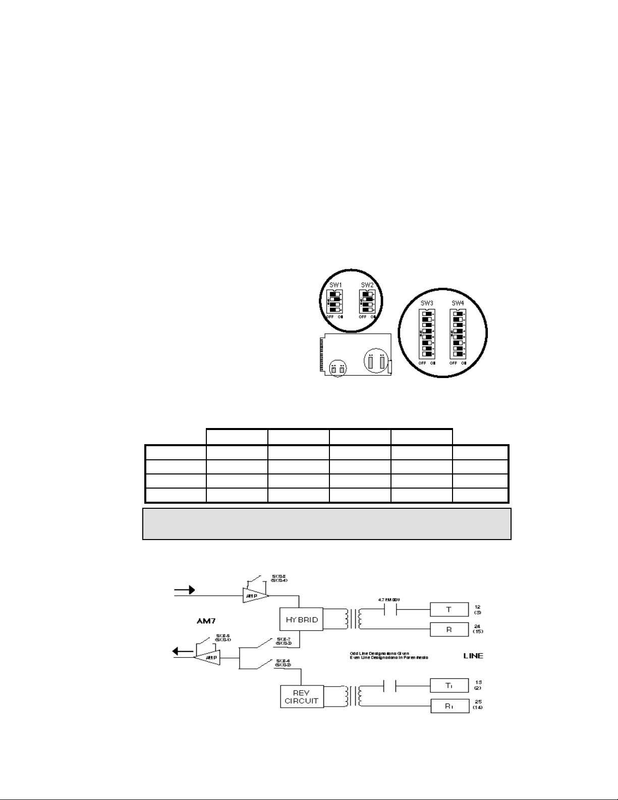
The two types of E&M linecards (2- and 4-wire) contain 4 DIP switches (SW1
thru SW4). The SW1 selections
indicate the card slot number as
previously shown. Default settings
depend on the card slot assignment.
The SW2 four position DIP switch
selects one of four Start Signals for
each E&M line. The Start Signal is
generated by the AM7 in response
to an incoming line seizure.
Table 1-6. E&M Linecard SW2 Settings
Start Signal Immediate Delay Wink Dial Tone
1 Off On Off On Odd Line
2 Off Off On On Odd Line
3 Off On Off On Even Line
4 Off Off On On Even Line
Figure 1-15. E&M Linecard DIP Switch
Locations
Note: Switch positions 1 and 2 control selections for the ODD numbered line.
Switch positions 3 and 4 control selections for the EVEN numbered line.
The SW3 eight position DIP switch selects both Audio Path gain and 2- or 4-wire
card configuration independently for each line.
Figure 1-16. Dial Pulse and DTMF E&M Line Interface Port Card
0014-S01.B_135 May 11, 1998
1-15
Page 29
Introduction (18-0014) AM7 User's Manual
Table 1-7. E&M Linecard SW3 Settings
Selection 1
5
2-Wire Mode Off On
4-Wire Mode On Off
0dB Gain AM7 to Line Off
-16dB Gain AM7 to Line On
0dB Gain AM7 from Line Off Off
-7dB Gain AM7 from Line
On
On
2
6
3
7
4
8
EVEN
Line
Odd Line
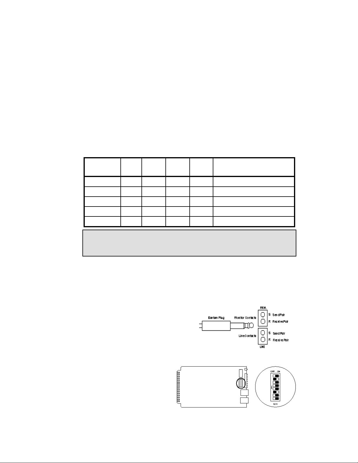
The SW4 eight position DIP switch selects the type of E&M Signaling Interface
for each line.
Figure 1-17. Dial Pulse and MF E&M Interface Port Card
July, 1997 0014-S01.B_135
1-16
Page 30
AM7 User’s Manual (18-0014) Introduction
Table 1-8. E&M Linecard SW4 Settings
Interface
Type
1 On Off On On M, E
2 Off Off Off On M, SBM, E, SG
3 Off Off Off On M, SGM, SBM, E
4 Off Off Off On M, SBM, E, SG
5 Off Off Off On M, E; Connect SG to SBM
1
5
2
6
3
7
4
EVEN Line
Connections
8
Odd Line Connections
Caution: Before connecting a cable configured for a Type 5 E&M interface,
make sure the SW4 switch positions are properly set. Failure to
comply may result in serious damage to the equipment.
1.3.8.3 Single Line PCM linecards
The Single Line PCM linecard provides access to 24 digital T1 channels, capable
of handling one call per channel. Each card has a set of 9 LED indicators,
including a green SEL (select) indicator and eight red DATA (1-4 transmit and 58 receive) indicators. The PCM linecard provides the AM7 with a 4-wire T1 line
interface with a send and receive pair of
contacts. The connection is made
through a Bantam jack, one for each
pair of "LINE" contacts. An additional
pair is used for line monitoring. The
PCM linecard contains one DIP switch,
SW1. The SW1 selections indicate the formatting of the card, the type and length
of cable used, and the card slot
number. The card may be
formatted for either an Extended
Super Frame (ESF) or D4
function by setting SW1 switch
1 ON to select ESF operation.
Figure 1-19. PCM Linecard DIP Switch Locations
Figure 1-18. T1 Line Interface
0014-S01.B_135 May 11, 1998
1-17
Page 31
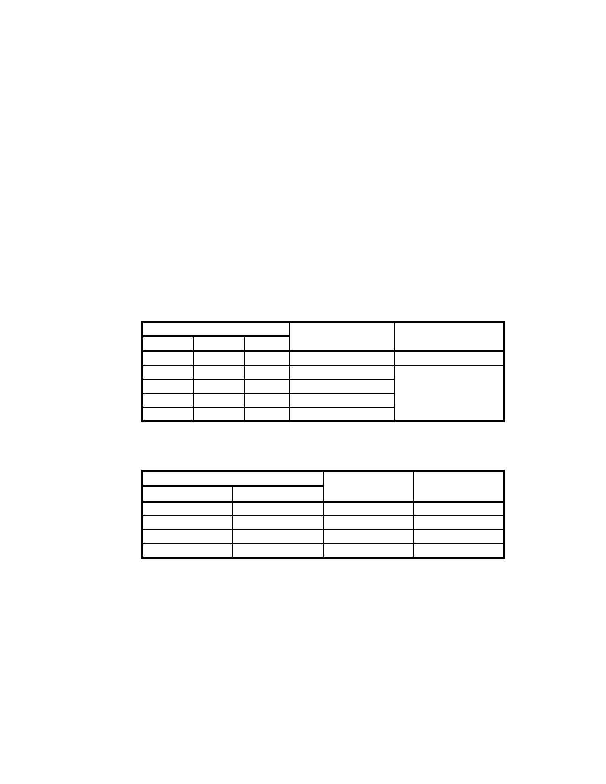
Introduction (18-0014) AM7 User's Manual
SW1 switch 1 is set to OFF to select D4 operation. The PCM linecard is capable
of utilizing MAT, ICOT, ABAM, PIC, or PULP cables of varying lengths for
data transmission and reception. SW1 switches 2 thru 4 are used to designate the
cable type and length.
Table 1-9. PCM Cable Length/Type Selection
DIP Switch Settings Line Length Cable Type
2 3 4
On On Off 0 to 220 ft. MAT & ICOT
On On Off 0 to 150 ft.
Off Off On 150 to 275 ft. ABAM, PIC
On Off On 275 to 550 ft. and PULP
Off On On 550 to 655 ft.
SW1 switches 5 and 6 are not used. The SW1 switch 7 and 8 selections indicate
the card slot number.
Table 1-10. PCM Linecard Slot/Span Selection
DIP Switch Settings PCM Card Slot Span #
7 8
Off Off Slot 1 1
On Off Slot 2 2
Off On Slot 3 3
On On Slot 4 4
1.3.8.4 Single Line DLC linecards
The Single Line DLC linecard provides access to 24 digital channels on each of 4
Spans, capable of handling one call per channel for a total of 96 calls. Each card
has a set of 9 LED indicators, including a green SEL (select) indicator, four red
bit status (SIG BITS) indicators, a red activity (ACTIVE) indicator and three red
ERROR indicators. Two sets of 2 Bantam jacks are provided for a SLC®96 line
interface; one set (LINE) for send (S) and receive (R) on the line, and one set
(MON.) for monitoring the line.
July, 1997 0014-S01.B_135
1-18
Page 32

AM7 User’s Manual (18-0014) Introduction
The DLC linecard has an internal DIP switch that is the same as shown for the
PCM linecard. The DIP switch (SW1) must be set correctly before the DLC
linecard is installed in a slot. Two modes of operation are available, Mode I
Option and Mode II Option.
The Mode I Option requires the installation of from 1 to 4 DLC linecards in slots
1 to 4 in the AM7. Each DLC linecard can send and receive 24 Mode I channels
on Spans A, B, C, or D. The Mode II Option requires DLC linecards to be
installed in slots 1 and/or 3. DLC cards that are installed in slots 2 and 4 are not
operational for the Mode II Option. Channels 01 thru 48 and alarms are
processed by Span A (Slot 1). Channels 49 thru 96 are processed by Span C
(Slot 3). If PCM linecards are installed in slots 2 and/or 4, they must be removed
to permit Mode II operation.
The DLC linecard cannot decode multi-frequency tones; therefore, at least one
Tone Receiver card must be installed for each DLC linecard installed.
1.3.8.5 Tone Receiver Cards
The Tone Receiver cards are shared as tone receivers in a central office switch.
When a T1 line programmed for tone dial (or tone dial and dial pulse) has an
incoming seizure (off-hook), a TT or MF receiver (whichever that line has been
set to decode) must be available before the start dial signal is returned. There are
a possible total of 8 MF receivers or 6 TT receivers on each card. The receivers
are divided into 2 groups "A" receivers and "B" receivers. Each receiver group is
independently programmed to decode either TT or MF. If a receiver group is
programmed to decode MF digits, 4 receivers are available. If a receiver group is
programmed to decode TT digits, 3 receivers are available. One Tone Receiver
card is required to decode TT or MF digits for each PCM or DLC card that has
been programmed to accept tone digits. Each card has a set of 8 LED indicators.
Each LED represents a receiver and will light when it's receiver is attached to
the line. The LED will go out when the receiver is released.
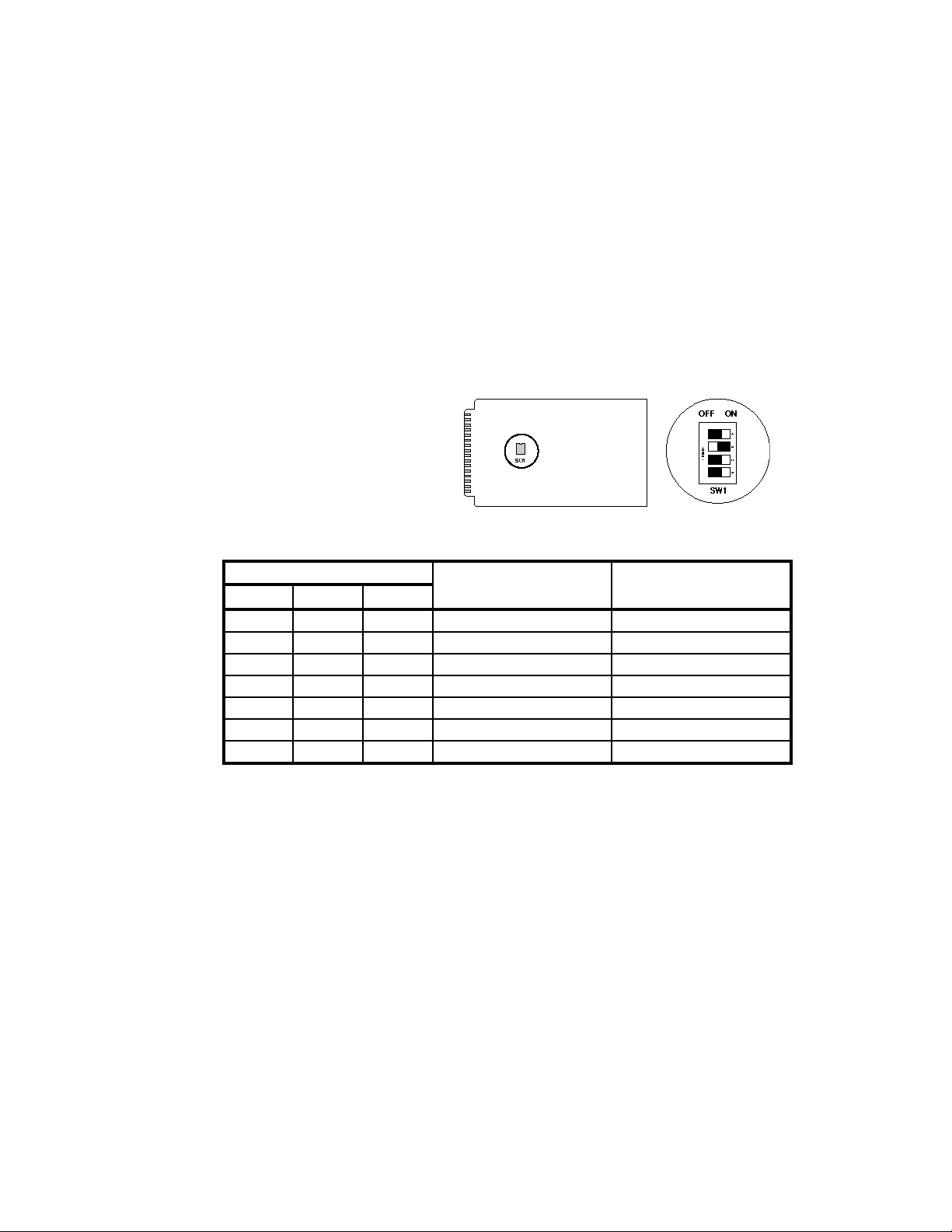
The Tone Receiver card may be set to decode MF or TT digits and contains one
DIP switch, SW1. SW1 selections indicate from 1 to 7 card slot numbers.
0014-S01.B_135 May 11, 1998
1-19
Page 33
Introduction (18-0014) AM7 User's Manual
The Tone Receiver card DIP
switch must be set to the card's
location. The Tone Receiver
cards must be installed from
right to left, starting with Slot
10.
Table 1-11. Tone Receiver Card SW1 Settings
DIP Switch Settings PCM Card Slot Install Order
1 2 3
On Off Off Slot 4 7 th
Off On Off Slot 5 6 th
On On Off Slot 6 5 th
Off Off On Slot 7 4 th
On Off On Slot 8 3 rd
Off On On Slot 9 2 nd
On On On Slot 10 1 st
Figure 1-20. Tone Receiver Card DIP Switch
1.4 Accessories
1.4.1 Transit Case
A transit case is available for secure commercial transportation of one or two
units, complete with cables and instruction manuals.
1.4.2 Rack Mounting Kit
The AM7 can be rack mounted in standard 19" racks with an optional rack mount
kit.
1.4.3 Spare Card Carrying Case
Used to store up to 20 line card modules.
July, 1997 0014-S01.B_135
1-20
Page 34

AM7 User’s Manual (18-0014) Introduction
0014-S01.B_135 May 11, 1998
1-21
Page 35

AM7 User’s Manual (18-0014) Getting Started
2. GETTING STARTED
The Getting Started section is presented to set up the AM7 for operation and
verify its proper operation. It begins with unpacking the unit, applying power,
and performing some of the AM7's basic operations.
2.1 Unpacking
Each AM7 is thoroughly tested and carefully packaged before shipment. Upon
receipt, inspect the outside of the shipping container for any damage. If damage
is noted, immediately contact the carrier. The name of the carrier will be noted
on the packing slip which is attached to the outside of the shipping container.
Note: Preserve the shipping container and packing materials in the event that the
unit may be shipped or returned in the future.
Open the shipping container and compare the contents with the packing slip.
Note any damage or shortages. Notify the carrier in the event of damage. Notify
Ameritec in the event of a shortage.
2.2 Power
The AM7 is configured with either a 115VAC or 220VAC 50/60Hz power
supply. A power cord is supplied with each unit.
Connect the AM7 to a clean and stable source of the indicated voltage. Pull the
power switch out and set it upward to the On position. A green LED (ON) lights
to verify that power is on. Pull and set the switch downward to turn power off.
Note: The AM7 provides approximately 30 days of memory backup. If power is
removed for a longer amount of time, all the parameters that have been set
up will return to factory default settings.
When power is applied to the AM7, the Parameter/Data Display shows the
default clock setting. A 24-hour clock is used. An entry of 2:00 pm on April 24,
1997, is made by entering 1400 042497. Once the data has been typed in, press
the ETRê key. The clock and calendar data is now programmed into memory.
0014-S02.B_126 July, 1997
2-1
Page 36

Getting Started (18-0014) AM7 User's Manual
2.3 Basic Operation
Several operations must be performed after the AM7 is received (with cards
already in slots with proper DIP switch settings) in order to prepare it for
operation.
Apply Power.
Enter System Parameters. Proper operation requires the entry of data into the
AM7 to direct it to perform required test tasking. System parameters are data
entered into the AM7 to tell it what form the information it receives will take,
and what to do with the information once it has been received. The AM7 has a
number of parameters unique to the overall system. Each parameter has a
factory-set default value that may be changed via the Program Keyboard or a
Remote keyboard.
Enter Line Parameters. In addition to the System parameters, the AM7 offers a
wide variety of Line Setup parameters that may be programmed to match specific
testing requirements. Each line can be individually programmed, or all lines can
be programmed with identical requirements. Each parameter has a factory-set
default value that may be changed via the Program Keyboard or a Remote
keyboard.
Enter Dialing Code. Dialing Codes are analogous to numbering plans
established and programmed within a digital central office. They are broken
down into 4 groups of 8 expected digits fields containing a string of digits that
must be matched in order to activate an Action Code sequence. When an
expected digit field (dialing code) is matched, from 1 to 8 actions associated with
that specific dialing code are performed.
Enter Action Codes. Action Codes contain the instructions to be performed by
the AM7. Each Dialing Code (expected digit set) can contain up to 8 Action
Codes (instructions) to be performed.
July, 1997 0014-S02.B_126
2-2
Page 37
AM7 User’s Manual (18-0014) Getting Started
2.3.1 Loop/Ground Start Card Operation
The AM7's ability to detect and decode incoming dialing sequences and switch
calls to the programmed output is demonstrated by connecting two standard
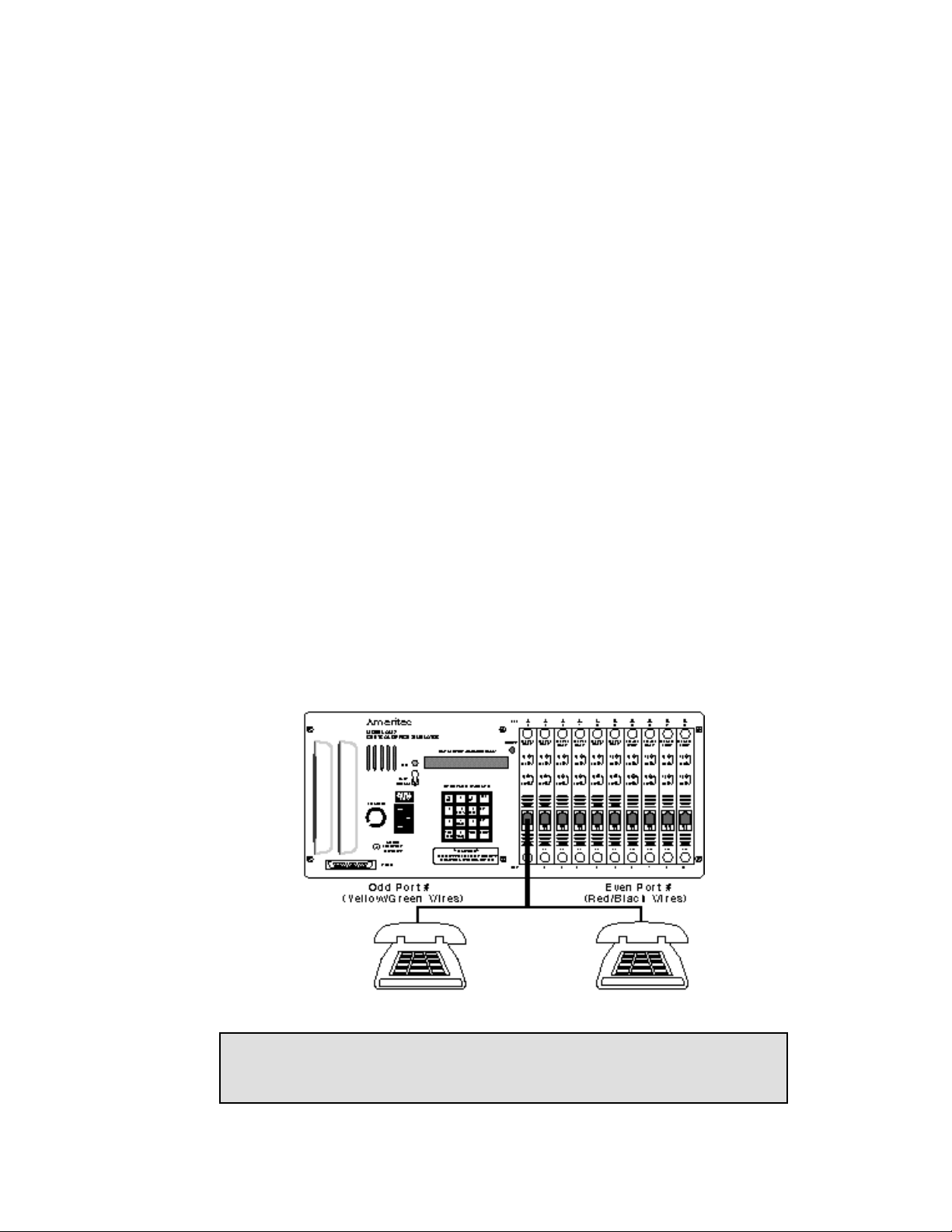
analog telephones to an AM7 interface Loop/Ground Start port card for Line 1
and 2 in slot 1. The AM7 is shipped from Ameritec with a factory default dialing
code expected digit program of 99999--. When the number 99999 followed by
an installed line's number (01 - 20) is dialed, either DTMF or Dial Pulse, the
AM7 responds by applying ringing to the line number dialed, and ringback to the
incoming line. If a mixture of PCM/DLC and analog cards are installed, card slot
1 will not be available for this operation. In this case, simply select the first
available Loop/Ground Start card and substitute the "01" and "02" after the
99999 with the appropriate port numbers. This provides a quick check of the
operation of the AM7 without the need for any initial programming.
Figure 2-1. Loop/Ground Start Card Operation
Note: The Loop/Ground Start cards are initially set for Ground Start operation.
To perform this operation, first set the SW2 Dip switch on the line card
for Loop Start. See Table 1-5 for instructions.
0014-S02.B_126 July, 1997
2-3
Page 38
Getting Started (18-0014) AM7 User's Manual
2.3.2 PCM Card Operation
If the AM7 is equipped with PCM linecards, follow the procedures outlined
below to get familiar with the unit. This exercise assumes that a channel bank
connected to the AM7's T1 port(s) is being used. If this is not the case, make the
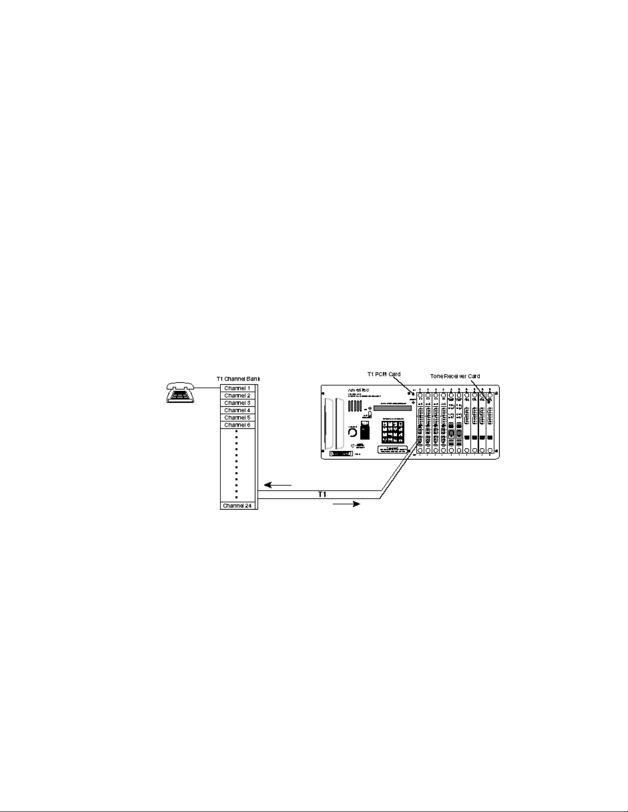
following adaptation. Connect a channel bank's T1 span line to PCM card
number 1 in slot 1 of the AM7. Connect an analog telephone to one of the Loop
Start ports of the channel bank.
Figure 2-2. PCM Card Operation
The AM7 with PCM cards is defaulted to emulate E&M signaling with Wink
Start dialing. It is also set to supply the 8kHz clock signal. The Tone Receivers,
if installed, are defaulted to accept MF dialing. The PCM channels are defaulted
to expect only dial pulse digits.
When a PCM card is being used, the Start Mode display appears only if E&M (3)
has been selected in the Emulation display. Four selections may be made for the
Start Mode: Immediate (1), Delay (2), the factory default Wink (3), or Dial Tone
(4). For this exercise, the Start Mode should be changed from Wink (3) to Dial
Tone (4). To do this, select the span and channel number where you expect to
see the activity generated by the phone connected to the channel bank. For
example, if the activity is to take place on channel 1 of Span 1, select 101 in the
display by keying SEL, 101, ETRê. Continue to press ETRê until you reach the
START MODE parameter. Press the 4 key. The flashing 3 will now read 4.
Press ETRê once again to enter this change.
July, 1997 0014-S02.B_126
2-4
Page 39

AM7 User’s Manual (18-0014) Getting Started
Continue to press ETRê until you reach TD=1 DP=2 AL=3 with a flashing 2. If
at least one Tone Receiver card is installed, press 3 followed by ETRê. You will
then be presented with the display TT=1 MF=2 with a flashing 2. Press 1
followed by ETRê. This will tell the channel to expect either dial pulse or
DTMF digits. If no Tone Receiver cards are installed, you must leave the
previous selection set to 2 (DP), and the digits received from the phone must be
Dial Pulse, not DTMF.
If Tone Receiver cards are installed, they must be set to expect DTMF (TT)
digits. To do this, select the unit parameters by keying SEL, 000, ETRê.
Continue pressing ETRê until you reach the parameter, REC10 1=T 2=M, with
22 being the current setting. Press 1 followed by ETRê. This sets group A of
the Tone Receiver card in slot 10 for DTMF.
Now select channel 101 by keying SEL, 101 (or the channel being used by the
telephone), ETRê. The upper eight red LED's on the PCM card will indicate the
status of the ABCD bits, with the top four LED's representing the Send bits and
the lower four LED's representing the Receive bits. If they are scrolling, it means
that there is a loss of synchronization between the channel bank and the AM7.
Be sure to verify proper connection if this is the case.
Go off hook on the telephone connected to the analog side of the channel bank.
You will see the data LED's change state to reflect the seizure.
When you hear the dial tone at the phone, dial 9999902. You will hear ringback
at the telephone and channel 2 of the PCM span will assume a ringing bit state.
If you have a second phone connected to the analog equivalent of time slot 2 of
the channel bank, the phone would now be ringing.
This all took place because the Dialing Codes default to expect 99999 plus two
other digits. These last two digits direct the call to that channel number of the
same span. Any other channel of any other span installed in the AM7, or any
other analog line installed in the AM7 can be dialed. See section 3.5.1, Dialing
Code Programming, for definitions for this area.
0014-S02.B_126 July, 1997
2-5
Page 40
Getting Started (18-0014) AM7 User's Manual
2.3.3 DLC Card Test
If the AM7 is equipped with DLC linecards, follow the procedures below to get
familiar with the unit. This exercise assumes that a SLC®96 remote terminal is
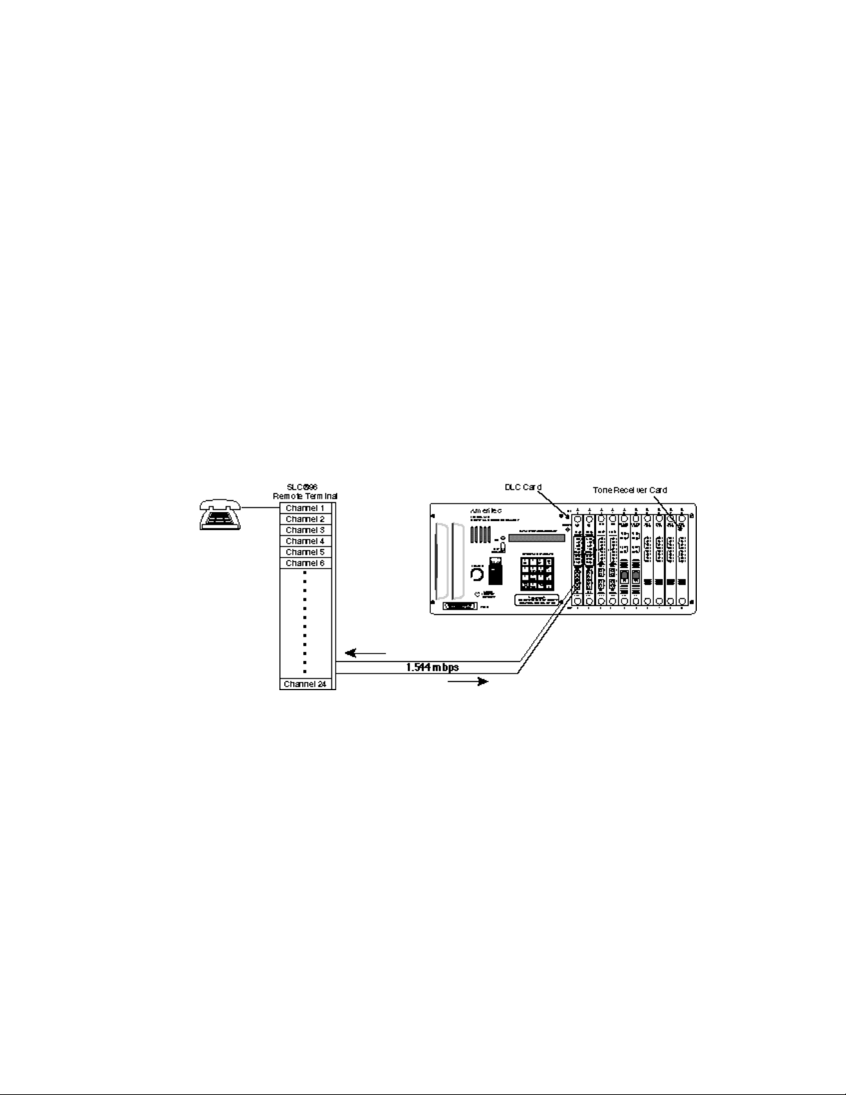
connected to the AM7's DLC ports. Connect the remote terminal's T1 span line
to DLC card number 1 in slot 1 of the AM7, and connect an analog telephone to
one of the analog loop start ports of the remote terminal.
Figure 2-3. DLC Card Test
The AM7 with DLC cards is defaulted to emulate Mode I operation. It is also set
to supply the 8kHz clock signal. The channels are defaulted to expect only Dial
Pulse digits.
Select channel 1 of span 1 by keying SEL, 101, ETRê. Continue to press ETRê
until you reach TD=1 DP=2 AL=3 with a flashing 2. If at least one Tone
Receiver card is installed, press 3, followed by ETRê. If no Tone Receiver cards
are installed, you must leave the previous selection set to 2 (DP) and the digits
received from the phone must be Dial Pulse, not DTMF.
If Tone Receiver cards are installed, they must be set to expect DTMF (TT)
digits. To do this, select the unit parameters by keying SEL, 000, ETRê.
Continue pressing ETRê until you reach the parameter, REC10 1=T 2=M, with
22 being the current setting. Press 1 followed by ETRê. This sets group A of
the Tone Receiver card in slot 10 for DTMF.
July, 1997 0014-S02.B_126
2-6
Page 41

AM7 User’s Manual (18-0014) Getting Started
Now select channel 101 by keying SEL, 101 (or the channel being used by the
telephone), ETRê. The upper four red LED's on the DLC card will indicate the
status of the AB bits, with the top two LED's representing the Send bits and the
lower two LED's representing the Receive bits. If they are scrolling, it means
that there is a loss of synchronization between the remote terminal and the AM7.
Be sure to verify proper connection if this is the case.
Go off hook on the telephone connected to the analog side of the remote
terminal. You will see the red LED's change state to reflect the seizure.
When you hear the dial tone at the phone, dial 9999902. You will hear ringback
at the telephone and channel 2 of the DLC span will assume a ringing bit state. If
you have a second phone connected to the analog equivalent of channel 2 of the
remote terminal, the phone would now be ringing.
This all took place because the Dialing Codes default to expect 99999 plus two
other digits. These last two digits direct the call to that channel number of the
same span. Any other channel of any other span installed in the AM7, or any
other analog line installed in the AM7 can be dialed. See section 3.5.1, Dialing
Code Programming, for definitions for this area.
0014-S02.B_126 July, 1997
2-7
Page 42

AM7 User’s Manual (18-0014) System Setup and Programming
3. SYSTEM SETUP AND PROGRAMMING
Proper operation requires the entry of data into the AM7 to direct it to perform
required test tasking. System parameters are data entered into the AM7 to tell it
what forms the information it receives will take, and what to do with the
information once it has been received.
3.1 System Parameters
The AM7 has a number of parameters unique to the overall system. Each
parameter has a factory set default value that may be changed when you are
setting up the system. The AM7 system parameters are illustrated and described
below in the order in which they appear on the Parameter/Data Display (display).
Note: If an attempt is made to enter improper data into a parameter field,
pressing any of the ETR keys will cause the display to blink. Proper data
may then be entered by pressing a numeric key or the SHIFT key.
3.1.1 Clock/Calendar
When power is turned on to the AM7,
the display shows the default time,
month, date, and year. A 24-hour clock is used. An entry of 2:00 pm on April
24, 1997, is made by pressing the following Program Keyboard (keypad) keys:
1400 042497. Once the data has been keyed in, press the ETRê key. The clock
and calendar data is programmed into memory, and the next system parameter
value appears. To display or change the clock after the system is running, press
SEL 000, then ETRê to access the system parameters.
CLOC 0000 000000
3.1.2 Automatic Printout
The AM7 is capable of automatically
generating hourly printouts of call
statistics via the RS232C port. The factory default is YES. To select NO, type in
0 and press the ETRê key (enter a "0").
0014-S03.B_ 127 July, 1997
3-1
AUTO PRT NO=0 1
Page 43

System Setup and Programming (18-0014) AM7 User's Manual
DT CON=1 INT=2 1
3.1.3 Dial Tone Select
A dial tone is a dual-tone waveform that
the AM7 uses as a Start Dial signal to let
you know that it is operating and ready to receive the number that you dial. The
AM7 can generate more than one type of dial tone. The factory default is "1" for
a continuous dial tone. An interrupted dial tone (ON/OFF cadence) may be
selected by entering a "2". If an interrupted dial tone is selected, two displays
become available that allow you to control the duration (from 0000 to 9900
milliseconds in 100ms steps) of the two-phase dial tone. The AM7 default
DT 1 0600: 1000
settings place the first part of the dial tone ON for 600ms and OFF for 1000ms;
the second part ON for 200ms and OFF for 200ms, after which the cadence
repeats.
DT 2 0200: 0200
3.1.4 Dial Tone Level and Frequency
The dial tone's default Levels (dBm) and Frequencies (Hz) of tone A and B of the
dual-tone waveform (displayed below) are set for a standard USA dial tone. The
Level (power of the signal) is negative, and may be set by entering values from
DT L-F A 13-0350 DT L-F B 13-0440
-03dBm to -39dBm. Frequencies (cycles of current in 1 second) may be set by
entering values from 0200Hz to 3500Hz. In order to generate a single tone, set
the A values to the desired level and frequency, and the Level of B to "99". A
Level of "99" disables a tone. Results may be unpredictable if A and B are set to
the same Frequency.
3.1.5 Ringing Frequency
The default frequency of the AM7's
ringing cadence (20.0Hz) can be changed
by entering values from 15Hz to 35Hz in 0.1Hz increments in order to simulate
various systems. Remember that a decimal point does not appear on the display.
RING FRE 200
July, 1997 0014-S03.B_ 127
3-2
Page 44

AM7 User’s Manual (18-0014) System Setup and Programming
3.1.6 Ringing Sequences
The AM7 provides a user-selected ringing cadence by means of two ringing
sequences (Ring 1 and Ring 2). These ringing sequences can be used to simulate
switch or central office ringing to provide an accurate simulation of a test
environment. Ring 1 defaults to an ON time of 2000ms and an OFF time of
RING 1 2000-4000 RING 2 0000-0000
4000ms. Ring 1 time can be programmed by entering values from 0100ms to
9900ms in 100ms increments. If Ring 2 is programmed for any other values than
the default times of 0000ms ON time and 0000ms OFF time, it provides its
ringing cadence after Ring 1. Ring 2 time can be programmed by entering values
from 0000ms to 9900ms in 100ms increments.
If, for example, a ring of 2 seconds ON, 4 seconds OFF, 2 seconds ON, 1 second
OFF is required; Ring 1 is programmed for 2000ms/4000ms, and Ring 2 is
programmed for 2000ms/1000ms.
3.1.7 Ringback Sequences
A ringback is a single or dual-tone waveform that the AM7 uses to advise the
caller that ringing voltage is being sent to the called party. The AM7 provides a
user-selected ringback cadence by means of two ringback sequences (Ringback 1
and Ringback 2). These ringback sequences can be used to simulate switch or
central office types to provide an accurate simulation of a test environment.
Ringback 1 defaults to an ON time of 2000ms and an OFF time of 4000ms.
RB 1 2000-4000 RB 2 0000-0000
Ringback 1 time can be programmed by entering values from 0100ms to 9900ms
in 100ms increments. If Ringback 2 is programmed for any other values than the
default times of 0000ms ON time and 0000ms OFF time, it provides its ringback
cadence after Ringback 1. Ringback 2 time can be programmed by entering
values from 0000ms to 9900ms in 100ms increments.
0014-S03.B_ 127 July, 1997
3-3
Page 45

System Setup and Programming (18-0014) AM7 User's Manual
If, for example, a ringback of 2 seconds ON, 4 seconds OFF, 2 seconds ON, 1
second OFF is required; Ringback 1 is programmed for 2000ms/4000ms, and
Ringback 2 is programmed for 2000ms/1000ms.
3.1.8 Ringback Level and Frequency
The ringback's default Levels (dBm) and Frequencies (Hz) of tone A and B
(displayed below) are set for a standard USA ringback. The Level is negative,
RB L-F A 19-0440 RB L-F B 19-0480
and may be set by entering values from -03dBm to -39dBm. Frequencies may be
set by entering values from 0200Hz to 3500Hz. In order to generate a single
tone, set the A values to the desired level and frequency, and the Level of B to
"99". A Level of "99" disables a tone. Results may be unpredictable if A and B
are set to the same Frequency.
3.1.9 Line Busy Sequences
Line busy is a dual-tone waveform that the AM7 uses to advise the caller that the
called party is off-hook. The AM7 provides a user-selected line busy cadence by
means of two line busy sequences (Line Busy 1 and Line Busy 2). These line
busy sequences can be used to simulate switch or central office types to provide
an accurate simulation of a test environment. Line Busy 1 defaults to an ON time
of 0500ms and an OFF time of 0500ms, and can be programmed by entering
LB 1 0500-0500 LB 2 0000-0000
values from 0100ms to 9900ms in 100ms increments. If Line Busy 2 is
programmed for any other values than the default times of 0000ms ON time and
0000ms OFF time, it provides its line busy cadence after Line Busy 1. Line Busy
2 time can be programmed by entering values from 0000ms to 9900ms in 100ms
increments.
If, for example, a line busy of 1/2 second ON, 1/2 second OFF, 1/2 second ON, 1
second OFF is required; Line Busy 1 is programmed for 500ms/500ms, and Line
Busy 2 is programmed for 500ms/1000ms.
July, 1997 0014-S03.B_ 127
3-4
Page 46

AM7 User’s Manual (18-0014) System Setup and Programming
3.1.10 Line Busy Level and Frequency
The Line Busy default Levels (dBm) and Frequencies (Hz) of tone A and B
(displayed below) are set for a standard USA line busy. The Level is negative,
and may be set by entering values from -03dBm to -39dBm. Frequencies may be
LB L-F A 24-0480 LB L-F B 24-0620
set by entering values from 0200Hz to 3500Hz. In order to generate a single
tone, set the A values to the desired level and frequency, and the Level of B to
"99". A Level of "99" disables a tone. Results may be unpredictable if A and B
are set to the same Frequency.
3.1.11 Reorder Sequences
Reorder is a dual-tone waveform that the AM7 uses to advise the caller that all
possible call paths through the AM7 are busy at the time of the call attempt. The
AM7 provides a user-selected reorder cadence by means of two Reorder
sequences (Reorder 1 and Reorder 2). These reorder sequences can be used to
simulate switch or central office types to provide an accurate simulation of a test
environment. Reorder 1 defaults to an ON time of 0200ms and an OFF time of
RO 1 0200-0300 RO 2 0000-0000
0300ms, and can be programmed by entering values from 0100ms to 9900ms in
100ms increments. If Reorder 2 is programmed for any other values than the
default times of 0000ms ON time and 0000ms OFF time, it provides its reorder
cadence after Reorder 1. Reorder 2 time can be programmed by entering values
from 0000ms to 9900ms in 100ms increments.
If, for example, a reorder of 2/10 second ON, 3/10 second OFF, 2/10 second ON,
1 second OFF is required; Reorder 1 is programmed for 200ms/300ms, and
Reorder 2 is programmed for 200ms/1000ms.
0014-S03.B_ 127 July, 1997
3-5
Page 47

System Setup and Programming (18-0014) AM7 User's Manual
3.1.12 Reorder Level and Frequency
The Reorder default Levels (dBm) and Frequencies (Hz) of tone A and B
(displayed below) are set for a standard USA reorder. The Level is negative, and
RO L-F A 24-0480 RO L-F B 24-0620
may be set by entering values from -03dBm to -39dBm. Frequencies may be set
by entering values from 0200Hz to 3500Hz. In order to generate a single tone,
set the A values to the desired level and frequency, and the Level of B to "99". A
Level of "99" disables a tone. Results may be unpredictable if A and B are set to
the same Frequency.
3.1.13 Tone Dialing Analyzer Report
The Tone Dialing Analyzer gives the AM7 the capability of analyzing the level,
frequency, twist, and digit timing of the two tones that make up a tone dialed
digit. Thresholds may be programmed for each parameter, and used for the
generation of a Tone Dialing Report. A Tone Dialing Report is generated by
entering a "1" when the "TD RPT"
display appears. Any measured
parameter that falls outside the programmed thresholds is flagged by an asterisk
in the Tone Dialing Report. See Section 3.3 for further information.
TT DIAL REPORT 14:32 05/14/97
LINE 04 - ALL DIGITS
LOW-BAND HIGH-BAND TWST OFF ON
FREQ DEV LEVEL FREQ DEV LEVEL TIME TIME
(HZ) (%) (dBm) (Hz) (%) (dBm) (dB) (mS) (mS)
5 0766 -0.5 -07 1332 -0.3 -05* +02 2220 0339
6 0766 -0.5 -07 1472 -0.3 -06 +01 0253 0291
4 0766 -0.5 -08 1216 +0.6 -06 +02 0242 0343
3 0699 +0.3 -08 1472 -0.3 -06 +02 0386 0194
1 0699 +0.3 -08 1216 +0.6 -06 +02 0175 0203
* 0850 -0.2 -18 ---- --- --- --- 1381 0017
! ---- --- -36* ---- --- --- --- 0039 0003
TD RPT Y=1 N=0 1
Parameter analysis is made on either a single line, or randomly on all lines. The
report may be set up to print only abnormal parameters and is sent, real time, out
the RS-232 port. When the Tone Dialing Report is selected, the following
thresholds can be programmed.
July, 1997 0014-S03.B_ 127
3-6
Page 48

AM7 User’s Manual (18-0014) System Setup and Programming
3.1.13.1 Low Tone Level
Each number generated by tone dialing, DTMF or MF, is made up of two
frequencies generated at the same time. The low (LO) and high (HI) frequency
each has a specific power level (measured in dBm). Factory defaults for the low
tone are -18 dBm minimum and -06 dBm
maximum. A range of low tone values
from 00 dBm to -40 dBm may be entered, in 1 dBm increments.
TD LO -18 -06
3.1.13.2 High Tone Level
Factory defaults for the high tone are
-18 dBm minimum and -06 dBm
maximum. A range of high tone values from 00 dBm to -40 dBm may be
entered, in 1 dBm increments.
3.1.13.3 Twist Level
The difference in dBm level between the high and low frequency of the tone
pairs is called "twist". The Twist value is arrived at by subtracting the low
frequency level from the high frequency level. Factory defaults are a maximum
negative twist of -6 dBm and a maximum
positive twist of +6 dBm. A range of
twist values from -12 dBm to +12 dBm may be entered, in 1 dBm increments.
3.1.13.4 Frequency Offset
The frequency offset parameter specifies the maximum frequency difference that
is to be allowed between received tones
and the expected tones. The factory
default allows for a 1.5% variance in the expected frequency. A range of
frequency offset values from 0.0 to 3.5% may be entered, in .1% increments.
TD HI -18 -06
TD TWIST -06 06
TD FRE 15
0014-S03.B_ 127 July, 1997
3-7
Page 49
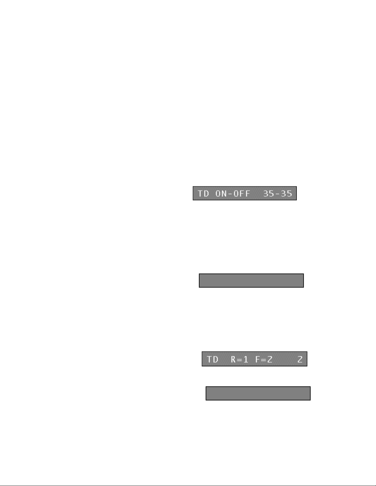
System Setup and Programming (18-0014) AM7 User's Manual
3.1.13.5 Tone ON/OFF Time
OFF Time is the duration of a quiet interval preceding a tone. ON Time is the
duration of the tone. The low limit for the tone pair ON and OFF times is set by
this parameter. The factory default
calls for ON and OFF times of 35ms.
A range of ON/OFF times from 20ms to 99ms may be entered, in 1ms
increments.
3.1.13.6 Tone Guard Time
Tones that are ON for the same amount of time or longer than the Tone Guard
Time are reported in the Tone Dialing Report; those with a shorter ON time do
not appear. The time is added to the OFF Time of the next reported tone. This
simplifies troubleshooting in cases where a fault in a Tone Dialer causes many
many spurious tones. Increasing the
Tone Guard Time filters such tones out
of the report, making it easier to interpret. When it is necessary to analyze
spurious tones, Tone Guard Time is reduced in order to view them. The factory
default is 20ms. A range of Tone Guard Times from 0ms to 99ms may be
entered, in 1ms increments.
TD GUARD 20
3.1.13.7 Tone Dial Line Analysis
Select the factory default Random Tone Dialing Analysis to randomly select
lines to analyze in the AM7. In random
mode (R=1), each time a line that the
analyzer is connected to becomes idle, it is reassigned to the next line that
becomes busy. In order to analyze a particular line, select the Fixed Line mode
(F=2), then select the line to be analyzed
(Line 15 for example).
July, 1997 0014-S03.B_ 127
3-8
TD LINE 015
Page 50

AM7 User’s Manual (18-0014) System Setup and Programming
3.1.13.8 Tone Dial All Digits Analysis
When "1" is entered, the Tone Dialing
Report includes all digits or events
analyzed. When "0" is entered, the report includes only digits or events whose
parameters are outside their programmed range.
TD ALL Y=1 N=0 1
3.1.14 Dial Pulse Report
The AM7 analyzes each decoded dial pulse digit for its speed, percent break, and
minimum interdigit time. Thresholds
may be programmed for each parameter,
and used for the generation of a Dial Pulse Report. A Dial Pulse Report is
generated by entering "1" when the "DP RPT" display appears.
Any measured parameter that falls outside the programmed thresholds is flagged
by an asterisk in the Dial Pulse Report. The report may be set up to print only
abnormal parameters and is sent, real time, out the RS232 port. Parameter
analysis is made on either a single line, or randomly on all lines. When the Dial
Pulse Report is selected, the following thresholds can be programmed.
DP RPT Y=1 N=0 1
3.1.14.1 Pulse Speed
Dial Pulse speed is the number of pulses a rotary dial can send in a given period
of time, typically 10 per second. A modem with a communications package can
send 20 pulses per second (pps). The
factory default for the speed of the dial
pulse is from 08pps to 12pps. A range of Dial Pulse Speed from 05pps to 30pps
may be entered, in 1pps increments.
DP SPEED 08-12
3.1.14.2 Pulse Break
A Dial Pulse is generated by a closed (break), then open period of current flow.
The factory default for an acceptable
amount of break in the duration of a
dial pulse is from 50% to 70% of the pulse. A range of dial pulse break from
20% to 80% may be entered, in 1% increments.
0014-S03.B_ 127 July, 1997
3-9
DP BREAC 50-70
Page 51
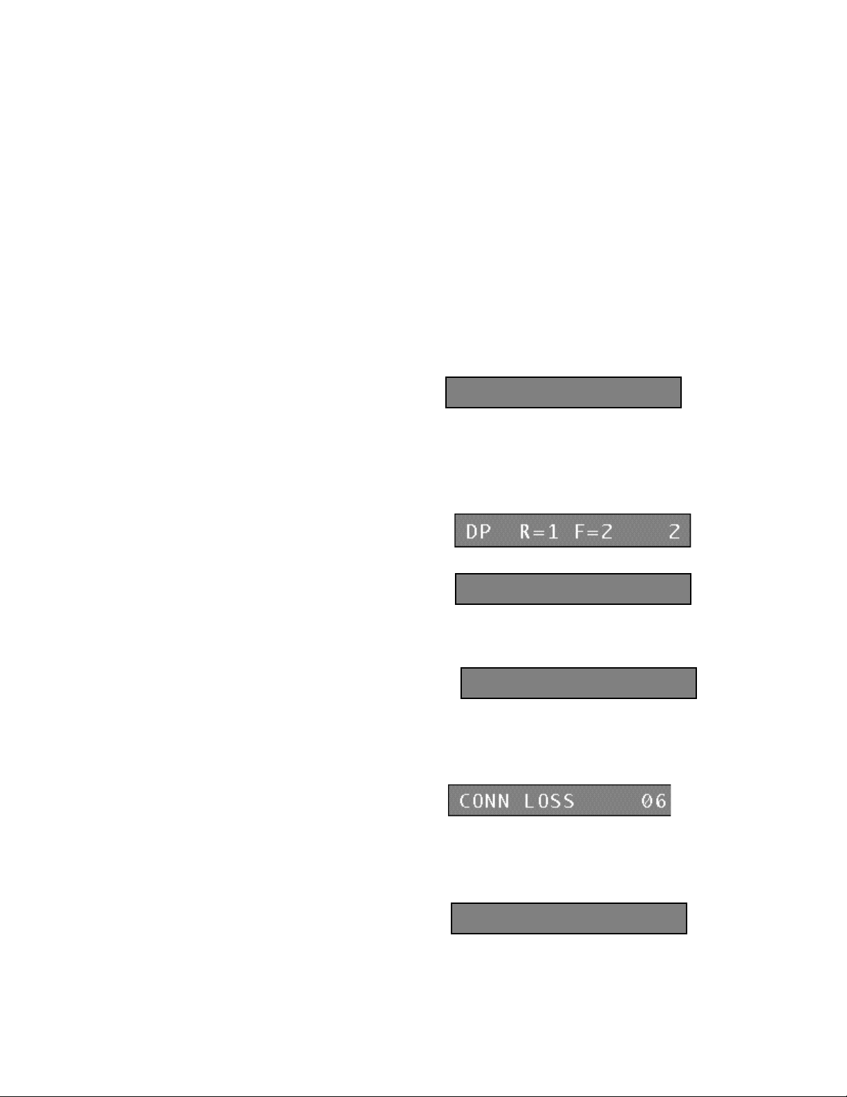
System Setup and Programming (18-0014) AM7 User's Manual
3.1.14.3 Pulse Interdigit Time
The factory default for the minimum
amount of time between the digits of
dial pulse signals is 400ms. A range of interdigit time from 200ms to 995ms may
be entered, in 5ms increments.
DP ID TIME 400
3.1.14.4 Dial Pulse Line Analysis
Select the factory default Random Pulse Dialing Analysis to randomly select
lines in the AM7. In random mode
(R=1), each time a line that the analyzer
is connected to becomes idle, it is reassigned to the next line that becomes busy.
In order to analyze a particular line,
select the Fixed Line mode (F=2), then
select the line to be analyzed (Line 15 for example).
DP LINE 015
3.1.14.5 Dial Pulse All Digits Analysis
When "1" is entered, the Dial Pulse
Report includes all digits analyzed, along
with their speed, percent break, and interdigit time. When "0" is entered, the
report includes only digit parameters outside their programmed range.
DP ALL Y=1 N=0 1
3.1.15 Connection Loss
The amount of connection loss (in dB)
from the incoming line to the outgoing
line through the AM7 can be simulated. The factory default is 6dB. A range of
connection loss from 0dB to 14dB may be entered, in 1 dB increments.
3.1.16 Master Span
The AM7 has an 8kHz internal clock
source. The clock source may also be
taken from the line connected to a PCM or DLC line card located in card slots 1
thru 4 in the AM7, by entering that card's slot number (1 - 4). An entry of zero is
the default entry for using the AM7 internal clock.
July, 1997 0014-S03.B_ 127
3-10
MASTER SPAN 0
Page 52

AM7 User’s Manual (18-0014) System Setup and Programming
REC10 1=T 2=M 22
3.1.17 Receiver Card Signaling Type
The receiver type must be selected for
each of the two receiver groups on a Tone
Receiver card. The first digit represents Group A, while the second digit
represents Group B. Enter a "1" for a Touch Tone (DTMF) receiver group of 3
receivers, or a "2" for a Multi-Frequency (MF) receiver group of 4 receivers.
The default setting is "22", setting both groups of receivers to decode MF. The
number immediately following "REC" indicates the slot (4-10) in which the Tone
Receiver card is installed. A separate display will appear for each installed Tone
Receiver card.
3.1.18 RS232C Port Configuration
The Baud Rate and Parity must be selected to match a device if it is connected to
BAUD 0300
the RS232C connector on the AM7. The factory default for an external device
Baud Rate is 300 Bps. 1200, 2400, 4800, and 9600 Bps Baud Rates are also
available for selection. Either EVEN (the factory default) or ODD parity may be
selected.
PARITY ODD=1 0
3.1.19 Software Version
The version display allows the version
of software installed in the AM7 to be
confirmed. This is a display-only parameter and cannot be changed.
0014-S03.B_ 127 July, 1997
3-11
VERSION _22
Page 53

System Setup and Programming (18-0014) AM7 User's Manual
SELECT 001
3.2 Line Parameters
In addition to the System parameters, the AM7 offers a wide variety of Line
Setup parameters that may be programmed to match your specific testing
requirements. Each line can be individually programmed, or all lines can be
programmed with identical parameters.
Normally the System Setup parameters are entered first, followed by the Line
Setup. If the System Setup is satisfactory, press the SEL key on the keypad.
When the SELECT display appears, enter
the 3-digit line number to be programmed.
3.2.1 Analog Card Line Parameters
Analog Line parameters are entered for lines 001 thru 020. If the selected line is
000, the AM7 will return to the clock/calendar display. An unacceptable entry
will cause the display to blink. Each of the following AM7 Line parameters are
described in the order of their displayed appearance.
3.2.1.1 Dial Tone Delay
The Dial Tone Delay allows changes to
be made in the amount of time it takes
for a device dialing in to the AM7 to receive a dial tone after it is detected as
being off hook. The default time is 0 seconds. A range of Dial Tone Delay time
from 0 to 99 seconds may be entered, in 1 second increments. A delay of greater
than 0 may be entered to simulate heavy calling volume being placed on the
system.
3.2.1.2 Auto Code
The Auto Code entry causes a line to have an automatic Dialing Code match with
Dialing Code 8 of its assigned Code
Group whenever it goes off hook. The
action designated by that Dialing Code is then executed. Dialing Code actions
are described in detail later in this manual.
July, 1997 0014-S03.B_ 127
START DELAY 00
AUTOCODE YES=1 0
3-12
Page 54
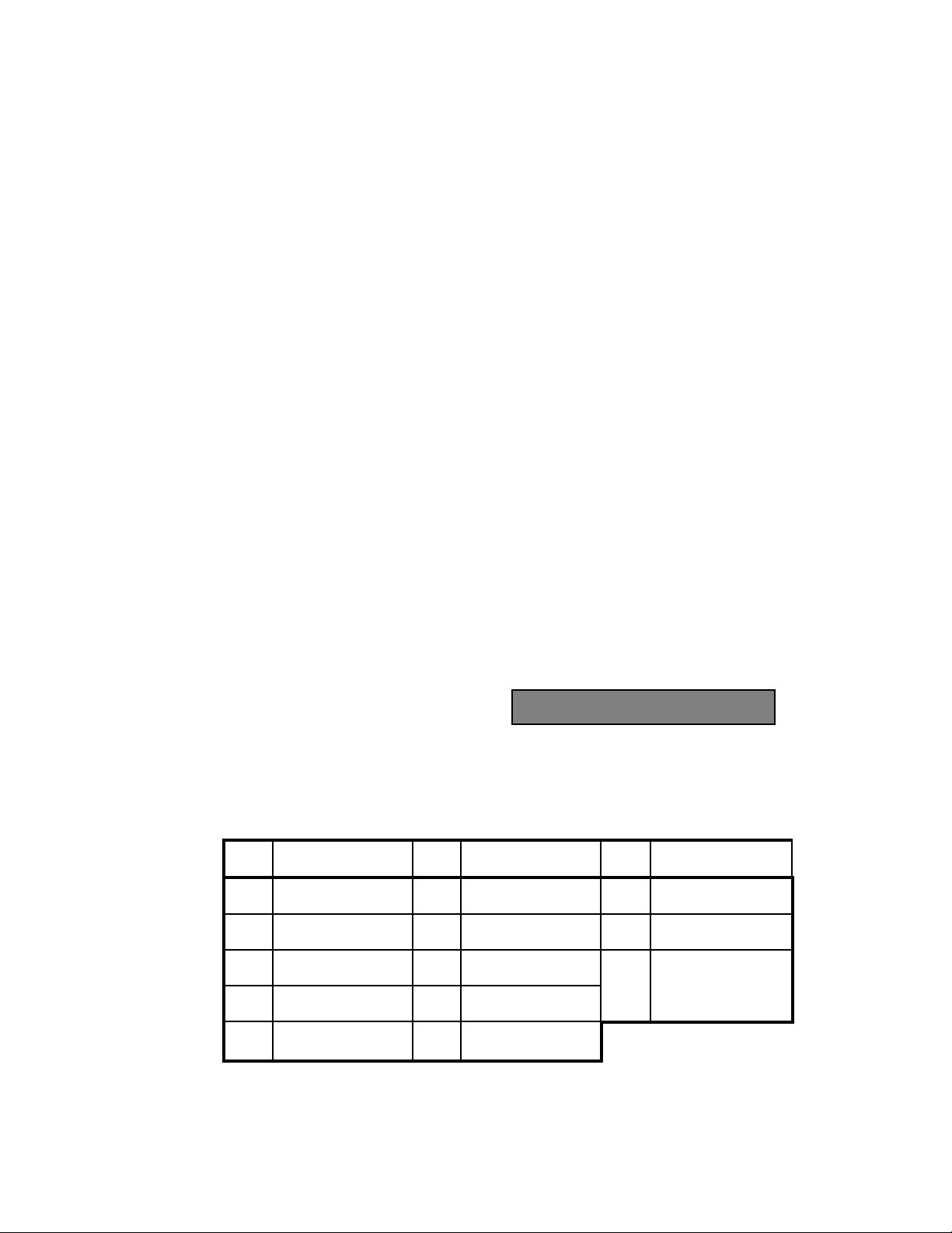
AM7 User’s Manual (18-0014) System Setup and Programming
The Auto Code feature allows a sequence of actions to be performed at off hook
time, even though no digits have been dialed. The factory default is 0 for NO.
Since the purpose of Auto Code is to have an automatic dialing code match at
off-hook without the need of incoming digits, there is generally no need to use a
tone receiver. With Auto Code, the dialing code match will be made regardless
of the presence or absence of incoming digits.
With Analog interfaces, the on-board tone receiver is permanently attached even
when it is not being used; as is generally the case when Auto Code is enabled.
3.2.1.3 Confirming Tone
At any time in a test sequence, the AM7 can be programmed to generate one of a
group of available frequencies. This "Step Sequence", or group of confirming
tones, is commonly used to indicate the
completion of a programmed function.
Step Sequences are discussed in detail in the section on Dialing Codes.
Thirteen different tones can be entered that will respond to the "send confirming
tone" step sequence command.
CONF TONE 0
Table 3-1. Confirming "Step Sequence" Tones
Code Freq. (Hz) Code Freq. (Hz) Code Freq. (Hz)
0 1010 (Test Tone) 1 1150 2 1275
3 1400 4 1525 5 1650
6 1775 7 1900 8 2025 Modem
9 2150 A 2275 Answerback Tone
B 2400 C 900
0014-S03.B_ 127 July, 1997
3-13
Page 55

System Setup and Programming (18-0014) AM7 User's Manual
3.2.1.4 Hunt Group
The AM7 can set up calls to be connected from an incoming port to a group of
outgoing ports called a Hunt Group. A Hunt Group is a series of telephone lines
organized in such a way that if the first line is busy, the second line is tried, and
so on until a free line is found. Any number of lines can be designated to
be part of from 1 to 8 Hunt Groups. The
default hunt group is Hunt Group 1. In
other words, a fully configured system would have all 20 lines programmed into
Hunt Group 1. To have two equal Hunt Groups, lines 1-10 could be assigned to
Hunt Group 1, and lines 11-20 assigned to Hunt Group 2. If a call is directed
into a hunt group (by means of an Action Code) that does not exist, a Reorder
Tone is generated.
HUNT GROUP 1
3.2.1.5 Answer Supervision
When a called party responds with an Off-Hook condition, the called party's
Central Office sends an Answer Supervision signal to the calling party's Central
Office. Answer Supervision monitors
AM7 lines to ensure that the called party
responded with an Off-Hook condition. The default, SUPU Y=1, indicates that
all loop or ground start calls switched through the AM7 will see a battery/ground
reversal (Answer Supervision) signal returned to the incoming port.
SUPU Y=1 N=0 1
3.2.1.6 Dialing Code Group
Dialing codes and step sequences, described in detail later in this manual, are
similar to the numbering plans used by a digital central office. The sequence of
digits allowed, and the steps to perform
when those digits are decoded, can be
established for the AM7. Dialing codes are contained in Group A thru Group D.
Each group contains eight dialing codes of from 1 to 12 expected digits. When a
line assigned to a given group matches expected digits, the step sequence
associated with those digits is performed. Each dialing code can execute only
one step sequence per call. Each line can be assigned to any of the four groups.
July, 1997 0014-S03.B_ 127
3-14
CODE GROUP A
Page 56
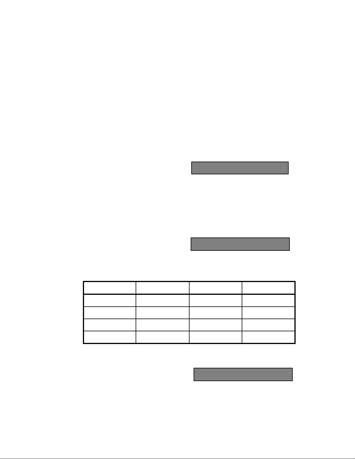
AM7 User’s Manual (18-0014) System Setup and Programming
3.2.1.7 Dialing Code Report
When a call across a line assigned to a
dialing code group fails to match any
expected digits, or extra digits are received after a match is made, a Dialing Code
Error report can be generated. The Dial Code Report default is YES, and prints
the digits that were received in error and not decoded. See Section 5.1.5 for
further information.
3.2.1.8 Call Progress Tones
Call Progress Tones are sent from a standard telephone company central office to
tell the caller the progress of the call
and are simulated by the AM7. The
tones are Dial Tone, Ringback, Line Busy, and Reorder, and can be placed in
either a NORMAL or LOW setting.
Table 3-2. Call Progress Tone Levels
Call Progress Tone Frequency Normal Level Low Level
Dial Tone 350 + 440 Hz -10dBm -30dBm
Ringback 440 + 480 Hz -16dBm -35dBm
Line Busy 480 + 620 Hz -21dBm -35dBm
DC RPT Y=1 N=0 1
TON NOR=1 LO=0 1
Reorder 480 + 620 Hz -21dBm -35dBm
3.2.1.9 Tone Dial (DTMF) and Dial Pulse Decode
Individual AM7 lines can be set up to
accept and decode Tone Dial (TD) digits,
Dial Pulse (DP) digits, or both (AL). The Tone Dial (DTMF) and Dial Pulse
Decode default is Dial Pulse (DP=2).
0014-S03.B_ 127 July, 1997
3-15
TD=1 DP=2 AL=3 3
Page 57

System Setup and Programming (18-0014) AM7 User's Manual
3.2.1.10 Flash Time
The Flash Hook is the receiver button that hangs up the phone. If the button is
pushed quickly, it can signal the Central Office to perform an action, such as
place a call on hold, switch to an incoming call (call waiting), or transfer a call.
The factory default set for the minimum
amount of time that an incoming line's On
Hook state is acknowledged as a Hook Flash is 450ms. A minimum Flash Time
of from 50ms to 1245ms may be entered, in 5ms increments. Flash Time may
not be entered with a value greater than or equal to Disconnect Time, or the Flash
Hook signal will no be recognized before the phone connection is shut down.
FLASH TIME 0450
3.2.1.11 Disconnect Time
If the receiver button is placed in an On Hook state for a sufficient period of
time, the AM7 recognizes that the phone connection has been shut down. The
factory default set for the minimum
amount of time that each line's On Hook
time will be recognized as a disconnect is 1000ms. A minimum Disconnect
Time of from 200ms to 1250ms may be entered, in 5ms increments. Disconnect
Time must be entered with a value greater than the Flash Time in order for a
Flash Hook signal to be recognized.
DISC TIME 1000
3.2.1.12 Wink Time
A Wink is a momentary interruption, indicating that a Central Office is ready to
receive the digits that have just been dialed. It is a single supervisory pulse,
signaled by a change in polarity on the line.
The Wink Time is the period of time that
the (battery/ground reversal) supervision
signal remains on the line. The factory default is 250ms. A Wink Time of from
50ms to 950ms may be entered, in 5ms increments.
July, 1997 0014-S03.B_ 127
3-16
WINC TIME 250
Page 58

AM7 User’s Manual (18-0014) System Setup and Programming
ATTEMPTS 00000
CODE 1 00000
NO CODE _00000
3.2.1.13 Call Activity Registers
While the AM7 is operating, it generates a realtime statistical peg count in a set
of Call Activity Registers. There are 10 Call Activity Registers per line, one
register to keep track of the call attempts made (ATTEMPTS), one register for
each of eight possible Dialing Codes (CODE 1-8), and one register for numbers
that don't match a Dialing Code's expected digits (NO CODE).
Each register is updated continuously (to a maximum of 65,535) and can be
observed by selecting its line and pressing the ETRê key until the register
appears. To view the same register in all lines, locate the register and press the
ETRè key to step sequentially through each line.
The contents of a line's register or all line registers can be printed by using the
SPCL (secondary function) key on the keypad. See Section 5, Reports, for
further information.
The Call Attempts Register increments each time the AM7 detects an incoming
Off Hook condition on the line. Each
time a line's incoming dialing code
matches a Dialing Code's expected digits,
its Code Register is incremented by one.
If a call attempt occurs without a dialing
code match, the No Code Register
increments by one. Typically, when one match per call is detected, the Call
Attempts Register equals the sum of the other 9 registers. However, if single
calls create multiple code matches, the Call Attempts Register contains less than
the other 9 registers.
0014-S03.B_ 127 July, 1997
3-17
Page 59

System Setup and Programming (18-0014) AM7 User's Manual
3.2.2 PCM (T1) Card Line Parameters
PCM line parameters are entered for the 24 channels of each Span (101-124, 201224, 301-324, 401-424). PCM Card Span Data Registers can be viewed by
entering the PCM card slot location via the SEL display (100, 200, 300, or 400).
The following Span Data Registers can be viewed by repeatedly pressing Enter:
• MF OFL - Occurs when no Multi-Frequency tone receiver was available
when first requested.
• TT OFL - Occurs when no Touch Tone tone receiver was available when
first requested.
• BPV - Bipolar is the predominant signaling method used for T1 lines. The
signal carrying the binary value alternates between positive and negative (1
and 0). A Bipolar Violation is the presence of two consecutive "one" bits of
the same polarity on a T1 line.
• SLIP - A SLIP is the condition under which a receiver of a digital signal
experiences starvation or overflow in its receive buffer due to a small
difference in the speeds of clocks and the clock (transmission rate) at the
transmitter. The receiver will drop or repeat a full TDM frame (193 bits on a
T1 line) in order to maintain synchronization.
• FERR - A Frame is a group of data bits in a specific format, usually
containing its own control information for addressing and error checking,
with a flag at each end to indicate the frame's beginning and end. The PCM
card uses an ESF (Extended Super Frame) or D4 format. In the 12 bit, D4
frame word, an error is counted when the 12-bit frame word received does
not conform to the standard 12-bit frame word pattern.
• CRC ERR - A Cyclical Redundancy Check is a process used to check the
integrity of a block of data. A CRC character is generated at the end of the
transmission. Its value is the hexadecimal value of the number of "ones" in
the data block. The receiving end makes the same calculations and compares
it to the transmitted value. If the calculations do not match, a CRC Error is
generated.
July, 1997 0014-S03.B_ 127
3-18
Page 60
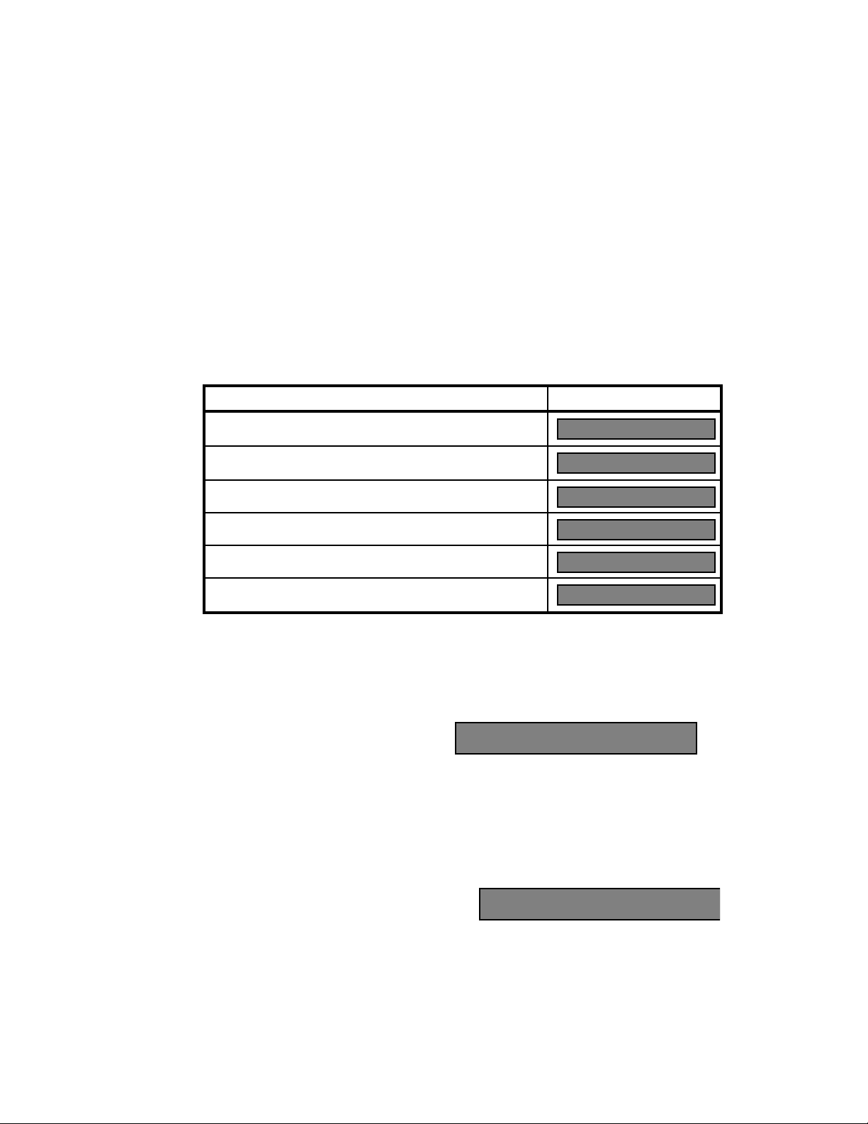
AM7 User’s Manual (18-0014) System Setup and Programming
START MODE 3
Table 3-3. PCM Card Span Data Registers
Data Register Display
MF OFL - The number of Multi Frequency receiver (decoder)
overflows.
TT OFL - The number of Touch Tone receiver (decoder)
overflows.
BPV - The number of Bipolar Violations for the selected Span.
SLIP - The number of Frame Slips for the selected Span.
FERR - The number of Framing Errors for the selected Span.
CRC ERR - The number of CRC (Cyclical Redundancy Check)
Errors for the selected Span.
Each of the following T1 line parameters are described in the order of their
displayed appearance.
3.2.2.1 Emulation
When a PCM card is being used, each
of the 24 PCM line channels can
emulate (pretend to be) a Ground Start, Loop Start or E&M line interface. The
factory default setting of 3 emulates an E&M interface.
3.2.2.2 Start Mode
MF OFL 00000
TT OFL 00000
BPU 00000
SLIP 00000
FERR 00000
CRC ERR 00000
EMULATION 3
The start signal is generated by the AM7 in response to an incoming line seizure
It signals that the AM7 has attached a receiver and is ready to receive digits.
When a PCM card is being used, the Start
Mode display appears only if E&M (3)
has been selected in the Emulation display.
0014-S03.B_ 127 July, 1997
3-19
Page 61

System Setup and Programming (18-0014) AM7 User's Manual
Four selections may be made for the Start Mode:
(1) Immediate - An Immediate Start indicates that the AM7 is immediately ready
to receive digits when an incoming line is seized.
(2) Delay - A Delay Start tells the AM7 will delay its readiness to receive digits
for the amount of time indicated by the Start Delay parameter.
(3) Wink - A Wink Start tells the AM7 to send a Wink when it is ready to
receive digits.
(4) Dial Tone - A Dial Tone Start tells the AM7 to send a Dial Tone when it is
ready to receive digits.
3.2.2.3 Dial Tone Delay
The Dial Tone Delay allows changes to
be made in the amount of time it takes
for a device dialing in to the AM7 to receive a dial tone after it is detected as
being off hook. The default time is 0 seconds. A range of Dial Tone Delay time
from 0 to 99 seconds may be entered, in 1 second increments. A delay of greater
than 0 may be entered to simulate heavy calling volume being placed on the
system.
START DELAY 00
3.2.2.4 Auto Code
The Auto Code entry causes a line to have an automatic Dialing Code match with
Dialing Code 8 of its assigned Code
Group whenever it goes off hook. The
action designated by that Dialing Code is then executed. Dialing Code actions
are described in detail later in this manual.
The Auto Code feature allows a sequence of actions to be performed at off hook
time, even though no digits have been dialed. The factory default is 0 for NO.
Since the purpose of Auto Code is to have an automatic dialing code match at
off-hook without the need of incoming digits, there is generally no need to use a
tone receiver. With Auto Code, the dialing code match will be made regardless
of the presence or absence of incoming digits.
July, 1997 0014-S03.B_ 127
3-20
AUTOCODE YES=1 0
Page 62

AM7 User’s Manual (18-0014) System Setup and Programming
With the PCM card's T1 interface, a tone receiver on a Tone Receiver Card is not
automatically attached when Auto Code is enabled. This is usually not a problem
because digits are not normally expected when Auto Code is enabled.
If an application requires a PCM card T1 receiver to be attached to a channel
programmed with Auto Code, the attachment is accomplished in one of two
ways:
• The receiver can be commanded to be attached by using an Action Code.
• A Dial Tone can be commanded to be sent by using an Action Code. A
receiver is automatically attached when a Dial Tone is sent.
3.2.2.5 Confirming Tone
At any time in a test sequence, the AM7 can be programmed to generate one of a
group of available frequencies. This "Step Sequence", or group of confirming
tones, is commonly used to indicate the
completion of a programmed function.
See Section 3.4.1.2, Action Code Step Sequences, for further information.
Thirteen different tones can be entered that will respond to the "send confirming
tone" step sequence command. See Table 3-1, Confirming "Step Sequence"
Tones, for further information.
CONF TONE 0
3.2.2.6 Hunt Group
The AM7 can set up calls to be connected from an incoming port to a group of
outgoing ports called a Hunt Group. A Hunt Group is a series of telephone lines
organized in such a way that if the first line is busy, the second line is tried, and
so on until a free line is found. Any number of lines can be designated to
be part of from 1 to 8 Hunt Groups. The
default hunt group is Hunt Group 1. In
other words, a fully configured system would have all 24 T1 channels on a PCM
card programmed into Hunt Group 1. To have two equal Hunt Groups, channels
1-12 could be assigned to Hunt Group 1, and channels 13-24 assigned to Hunt
Group 2. If a call is directed into a hunt group (by means of an Action Code) that
does not exist, a Reorder Tone is generated.
0014-S03.B_ 127 July, 1997
3-21
HUNT GROUP 1
Page 63

System Setup and Programming (18-0014) AM7 User's Manual
3.2.2.7 Answer Supervision
When a called party responds with an Off-Hook condition, the called party's
Central Office sends an Answer Supervision signal to the calling party's Central
Office. Answer Supervision monitors
AM7 lines to ensure that the called party
responded with an Off-Hook condition. The default, SUPU Y=1, indicates that
all T1 calls switched through the AM7's PCM cards will generate an A,B bit state
change for that T1 channel.
SUPU Y=1 N=0 1
3.2.2.8 Dialing Code Group
Dialing codes and step sequences, described in detail later in this manual, are
similar to the numbering plans used by a digital central office. The sequence of
digits allowed, and the steps to perform
when those digits are decoded, can be
established for the AM7. Dialing codes are contained in Group A thru Group D.
Each group contains eight dialing codes of from 1 to 12 expected digits. When a
line assigned to a given group matches expected digits, the step sequence
associated with those digits is performed. Each dialing code can execute only
one step sequence per call. Each line can be assigned to any of the four groups.
CODE GROUP A
3.2.2.9 Dialing Code Report
When a line assigned to a dialing code
group fails to match any expected digits,
or extra digits are received after a match is made, a Dialing Code Error report can
be generated. The Dial Code Report default is YES, and prints the digits that
were received in error and not decoded.
July, 1997 0014-S03.B_ 127
3-22
DC RPT Y=1 N=0 1
Page 64

AM7 User’s Manual (18-0014) System Setup and Programming
3.2.2.10 Call Progress Tones
Call Progress Tones are sent from a standard telephone company central office to
tell the caller the progress of the call
and are simulated by the AM7. The
tones are Dial Tone, Ringback, Time Busy, and Reorder, and can be placed in
either a NORMAL or LOW setting. See Table 3-2, Call Progress Tone Levels,
for further information.
TON NOR=1 LO=0 1
3.2.2.11 Tone Dial and Dial Pulse Decode
Individual AM7 lines can be set up
to accept and decode Tone Dial (TD)
digits, Dial Pulse (DP) digits, or both (AL). The Tone Dial and Dial Pulse
Decode default is Dial Pulse (DP=2). To select anything other than Dial Pulse,
one or more Tone Receiver cards must be installed.
TD=1 DP=2 AL=3 3
3.2.2.12 Tone Receiver Type Required
The Tone Receiver Type Required
display follows the Tone Dial and
Dial Pulse Decode display if the AM7 is configured for a PCM T1 card and
either Tone (TD=1) or both Tone and Pulse (AL=3) has been previously selected.
The required type of tone receiver (decoder): Touch Tone (TT=1) or the factory
default setting of Multi Frequency (MF=2) may now be selected.
TT=1 MF=2 1
3.2.2.13 Flash Time
The Flash Hook is the receiver button that hangs up the phone. If the button is
pushed quickly, it can signal the Central Office to perform an action, such as
place a call on hold, switch to an incoming call (call waiting), or transfer a call.
The factory default set for the minimum
amount of time that an incoming line's On
Hook state is acknowledged as a Hook Flash is 450ms. A minimum Flash Time
of from 50ms to 1245ms may be entered, in 5ms increments. Flash Time may
not be entered with a value greater than or equal to Disconnect Time, or the Flash
Hook signal will no be recognized before the phone connection is shut down.
0014-S03.B_ 127 July, 1997
3-23
FLASH TIME 0450
Page 65

System Setup and Programming (18-0014) AM7 User's Manual
3.2.2.14 Disconnect Time
If the receiver button is placed in an On Hook state for a sufficient period of
time, the AM7 recognizes that the phone connection has been shut down. The
factory default set for the minimum
amount of time that each line's On Hook
time will be recognized as a disconnect is 1000ms. A minimum Disconnect
Time of from 200ms to 1250ms may be entered, in 5ms increments. Disconnect
Time must be entered with a value greater than the Flash Time in order for a
Flash Hook signal to be recognized.
DISC TIME 1000
3.2.2.15 Wink Time
A Wink is a momentary interruption, indicating that a Central Office is ready to
receive the digits that have just been dialed. It is a single supervisory pulse,
signaled by a change in polarity on the line.
The Wink Time is the period of time
that the E&M wink (battery/ground
reversal) supervision signal remains on the line. The factory default is 250ms. A
Wink Time of from 50ms to 950ms may be entered, in 5ms increments.
WINC TIME 250
3.2.2.16 Call Activity Registers
While the AM7 is operating, it generates a realtime statistical peg count in each
line's Call Activity Registers. There are 10 Call Activity Registers, one register
to keep track of the call attempts made (ATTEMPTS), one register for each of
eight possible Dialing Codes (CODE 1-8), and one register for numbers that don't
match a Dialing Code's expected digits (NO CODE).
Each register is updated continuously (to a maximum of 65,535) and can be
observed by selecting its line and pressing the Enter/down arrow key until the
register appears. To view the same register in all lines, locate the register and
press the Enter/right arrow key to step sequentially through each line. The
contents of a line's register or all line registers can be printed by using the SPCL
(secondary function) key on the keypad.
July, 1997 0014-S03.B_ 127
3-24
Page 66

AM7 User’s Manual (18-0014) System Setup and Programming
ATTEMPTS 00000
CODE 1 00000
NO CODE _00000
The Call Attempts Register increments each time the AM7 detects an incoming
Off Hook condition on the line. Each
time a line's incoming dialing code
matches a Dialing Code's expected digits,
its Code Register is incremented by one.
If a call attempt occurs without a dialing
code match, the No Code Register
increments by one. Typically, when one match per call is detected, the Call
Attempts Register equals the sum of the other 9 registers. However, if single
calls create multiple code matches, the Call Attempts Register contains less than
the other 9 registers.
0014-S03.B_ 127 July, 1997
3-25
Page 67

System Setup and Programming (18-0014) AM7 User's Manual
3.2.3 DLC (SLC®96) Card Line Parameters
Each of the DLC Cards (slots 1-4) can be configured to simulate a SLC®96 Span.
SLC®96 is a short haul (between 200 yds and 20 miles) multiplexing device
which enables up to 96 telephone customers to be served on three pairs of wires.
Tone Receiver cards must also be installed in the AM7 if tests require DTMF
dialing. The number of cards depends upon the number of DLC cards installed.
A SLC®96 Span is capable of operating in two different modes, Mode I and
Mode II.
• MODE I - Mode I provides 96 carrier channels and dedicates one channel
to each subscriber line. This configuration requires four T1 lines. To use
the SLC®96 Mode I Option, one to four DLC cards must be installed in the
AM7. Each DLC card can send and receive 24 Mode I channels on Spans
A, B, C, or D.
Mode I refers to a nonconcentrated shelf group that is served by two
primary T1 lines. Each shelf in the shelf group is served by a dedicated T1
line given the same designation (A, B, C, or D) as the shelf. For example,
if shelf group AB is operating in Mode I, its A shelf will be served by the
A T1 line and its B shelf by the B T1 line. If all twelve slots of a shelf are
filled with dual-circuit channel units, the twenty-four time slots on the T1
line associated with that shelf are fully used. Single-circuit channel units
may be substituted for dual-circuit channel units without restrictions, but
for each single-circuit channel unit that replaces a dual-circuit unit, one
DS1 timeslot on the T1 line will be unused.
• MODE II - Mode II concentrates shelf groups of 48 subscriber lines onto
24 carrier channels per shelf group. This configuration requires two main
T1 lines per system. To use the SLC®96 Mode II Option, the DLC cards
must be installed in slots 1 and/or 3. DLC cards in slots 2 and 4 (if
installed) are not operational (if PCM T1 option boards are installed in
slots 2 or 4, they must be removed in order to use the SLC®96 Mode II
Option). Channels 01 - 48 and alarms are processed by the Span A, and
channels 49 - 96 are processed by Span C.
July, 1997 0014-S03.B_ 127
3-26
Page 68
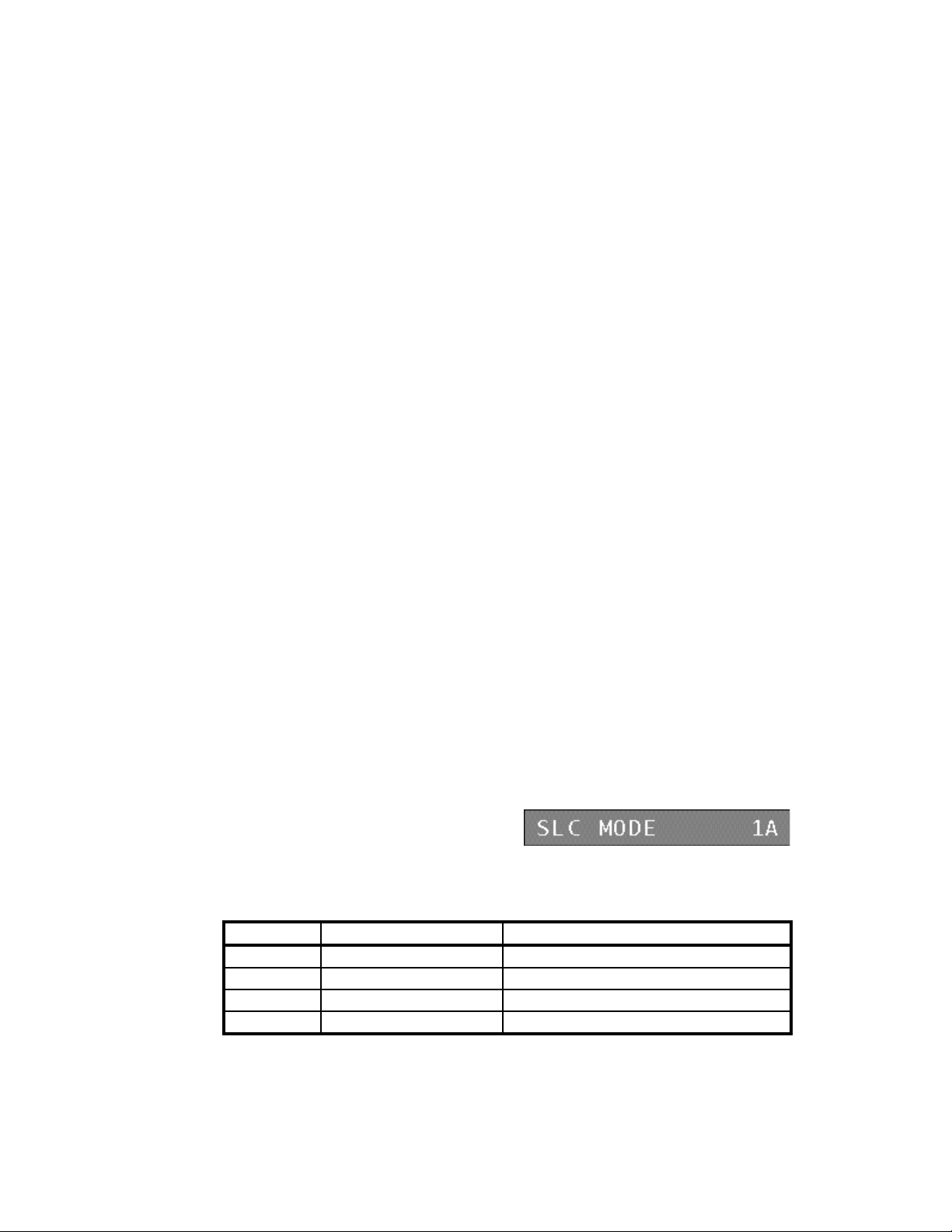
AM7 User’s Manual (18-0014) System Setup and Programming
Mode II refers to a shelf group that uses a concentrator and is connected to
the Local Digital Switch by one primary T1 line. The A T1 line is used for
shelf group AB and the C T1 line is used for shelf group CD. A maximum
of 24 dual single party or multiparty channel units may be inserted into the
channel unit slots in a Mode II shelf group which results in up to 48 lines
competing for the 24 DS1 time slots and yields a 2:1 concentration ratio.
Although either dual- or single-circuit channel units can be used in a Mode
II shelf group, only the dual-circuit types are concentrated. The
concentration ratio remains 2:1 even if single-circuit channel units are
substituted for dual-circuit units, since each single-circuit channel unit
displaces a dual-circuit channel unit and permanently occupies one DS0
time slot.
In order to maintain sufficient traffic capacity, a minimum of 16 DS0 time
slots on each T1 line must be available for concentrated traffic. Hence, a
maximum of 8 single-circuit channel units may be present in a Mode II
shelf group. Furthermore, in a SLC®96 remote terminal, coin or special
service channel units may only be used in the four rightmost channel unit
slots of each shelf
When the line number for the DLC card
has been entered, the SLC Mode display
appears. The following settings are valid for the positions of DLC cards. DLC
cards must be in slots 1 and/or 3 to set the SLC Mode to 2A or 2C.
Table 3-4. DLC Card Mode & Span Setting
Slot Line Mode and Span Setting
1 Line 100 1A, 1B, 1C, 1D, 2A, 2C
2 Line 200 1A, 1B, 1C, 1D
3 Line 300 1A, 1B, 1C, 1D, 2A, 2C
4 Line 400 1A, 1B, 1C, 1D
0014-S03.B_ 127 July, 1997
3-27
Page 69

System Setup and Programming (18-0014) AM7 User's Manual
DLC line parameters are entered for the 24 channels of each Span (101-124, 201224, 301-324, 401-424). DLC Card Span Data Registers can be viewed by
entering the DLC card slot location via the SEL display (100, 200, 300, or 400).
The following Span Data Registers can be viewed by repeatedly pressing Enter to
scroll through them.
• TT OFL - Occurs when no Touch Tone tone receiver was available when
first requested.
• BPV - Bipolar is the predominant signaling method used for T1 lines. The
signal carrying the binary value alternates between positive and negative (1
and 0). A Bipolar Violation is the presence of two consecutive "one" bits of
the same polarity on a T1 line.
• SLIP - A SLIP is the condition under which a receiver of a digital signal
experiences starvation or overflow in its receive buffer due to a small
difference in the speeds of clocks and the clock (transmission rate) at the
transmitter. The receiver will drop or repeat a full frame (193 bits on a T1
line) in order to maintain synchronization.
• FERR - A Frame is a group of data bits in a specific format, usually
containing its own control information for addressing and error checking,
with a flag at each end to indicate the frame's beginning and end. The PCM
card uses an ESF (Extended Super Frame) or D4 format. In the 12 bit, D4
frame word, an error is counted when the 12-bit frame word received does
not conform to the standard 12-bit frame word pattern.
• SLC®96 Alarm Display - The SLC®96 Alarm Display consists of 12
characters. If no alarms are present the display consists of a series of dashes.
If an alarm is detected, the dash is replaced with an "A". The LED position
of the "A" corresponds to the type of error.
July, 1997 0014-S03.B_ 127
3-28
Page 70

AM7 User’s Manual (18-0014) System Setup and Programming
Table 3-5. SLC®96 Alarm Character Meaning
Major Alarm - A system state characterized
by a loss of service to subscribers served
by a shelf or shelf group, exists. If a shelf
alarm condition is also present, the shelf
alarm indicates the location of the major
alarm fault condition.
Minor Alarm - A system state
characterized by a non-service affecting
fault, exists. If a far end loop condition is
also present, the far end loop indicates the
LED
Position
5 Major Alarm
6 Minor Alarm
7 Power/Misc Alarm
8 A Shelf Alarm
Character Meaning
location of the minor alarm condition.
Power/Miscellaneous Alarm - A remote
terminal site may be configured to allow
two or more remote terminals to share
common power and maintenance
equipment. Each remote terminal can
transmit a Power/Miscellaneous alarm.
One remote terminal's Power/
Miscellaneous alarm always indicates that
AC power is unavailable at the location.
The other remote terminal's Power/
Miscellaneous alarms can be used to
transmit pre-arranged alarm conditions. An
active Power/Miscellaneous alarm shall
also raise a major or minor alarm as
indicated below:
9 B Shelf Alarm
10 C Shelf Alarm
11 D Shelf Alarm
12 A Line Far End Loop (FELP)
13 B Line FELP
14 C Line FELP
15 D Line FELP
16 P Line FELP
• For remote terminals located in electronic equipment enclosures, Major
Power/Miscellaneous alarms include high temperature, smoke, fire, etc.
• For remote terminals located in controlled environment vaults, Major Power/
Miscellaneous alarms include toxic gas, explosive gas, high water, etc.
• For remote terminals located in electronic equipment enclosures, Minor
Power/ Miscellaneous alarms include, for example, an open door.
Shelf Alarms - The four shelf alarm bit patterns, one corresponding to each shelf,
indicate that a shelf alarm condition exists. A shelf alarm condition is defined as
a system state characterized by the loss of a shelf's operational integrity. A major
alarm condition is also indicated whenever a shelf alarm condition exists.
0014-S03.B_ 127 July, 1997
3-29
Page 71
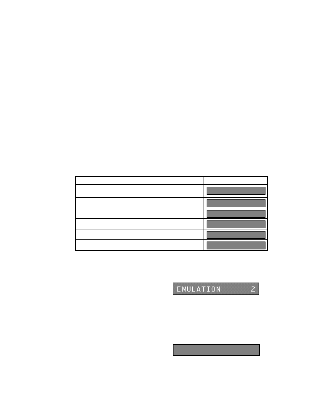
System Setup and Programming (18-0014) AM7 User's Manual
Far End Loop - These five bit patterns, each corresponding to a particular line (A,
B, C, D, or P), may be sent to request that the far end loop the incoming digital
bit stream to the output bit stream. This permits Operating Company craft to
perform single-ended fault locating of the looped digital line from the near end.
A minor alarm condition is also indicated whenever a far end loop condition
exists. The P-line (over-voltage and/or over-current protection) is unavailable.
Table 3-6. DLC Card Span Data Registers
Data Register Display
TT OFL - The number of Touch Tone receiver (decoder)
overflows. (No TT receiver available when first requested)
BPV - The number of Bipolar Violations for the selected Span.
SLIP - The number of Frame Slips for the selected Span.
FERR - The number of Framing Errors for the selected Span.
SLC®96 Alarm Display.
SLC®96 Version Software. A display-only parameter.
TT OFL 00000
BPU 00000
SLIP 00000
FERR 00000
---AAAAAAAAAAAA
SLC VERSION 01B
Each of the following AM7 Line parameters are described in the order of their
displayed appearance.
3.2.3.1 Emulation
When a DLC card is being used, each of
the 24 DLC line channels can emulate a
Ground Start or Loop Start interface. The factory default setting of 2 emulates a
Loop Start interface. Ground Start (1) can be used by SLC®96 Mode I only, both
Mode I & II can use Loop Start (2) emulation.
3.2.3.2 Trunk Assignment Delay
The Trunk Assignment Delay parameter is only available for SLC®96 simulation
Mode II operation via a DLC card. The
TCA DELAY, with a factory default of
00 seconds, simulates congestion on a SLC®96 Span. A range of TCA Delay
time from 00 to 99 seconds may be entered, in 1 second increments.
July, 1997 0014-S03.B_ 127
3-30
TCA DELAY 00
Page 72

AM7 User’s Manual (18-0014) System Setup and Programming
3.2.3.3 Dial Tone Delay
The Dial Tone Delay allows changes to
be made in the amount of time it takes
for a device dialing in to the AM7 to receive a dial tone after it is detected as
being off hook. The default time is 0 seconds. A range of Dial Tone Delay time
from 0 to 99 seconds may be entered, in 1 second increments. A delay of greater
than 0 may be entered to simulate heavy calling volume being placed on the
system.
START DELAY 00
3.2.3.4 Auto Code
The Auto Code entry causes a line to have an automatic Dialing Code match with
Dialing Code 8 of its assigned Code
Group whenever it goes off hook. The
action designated by that Dialing Code is then executed. Dialing Code actions
are described in detail later in this manual.
The Auto Code feature allows a sequence of actions to be performed at off hook
time, even though no digits have been dialed. The factory default is 0 for NO.
AUTOCODE YES=1 0
Since the purpose of Auto Code is to have an automatic dialing code match at
off-hook without the need of incoming digits, there is generally no need to use a
tone receiver. With Auto Code, the dialing code match will be made regardless
of the presence or absence of incoming digits.
With the DLC card's SLC®96 interface, a tone receiver on a Tone Receiver Card
is not automatically attached when Auto Code is enabled. This is usually not a
problem because digits are not normally expected when Auto Code is enabled.
If an application requires an SLC®96 receiver to be attached to a channel
programmed with Auto Code, the attachment is accomplished in one of two
ways:
• The receiver can be commanded to be attached by using an Action Code.
• A Dial Tone can be commanded to be sent by using an Action Code. A
receiver is automatically attached when a Dial Tone is sent.
0014-S03.B_ 127 July, 1997
3-31
Page 73

System Setup and Programming (18-0014) AM7 User's Manual
3.2.3.5 Confirming Tone
At any time in a test sequence, the AM7 can be programmed to generate one of a
group of available frequencies. This "Step Sequence", or group of confirming
tones, is commonly used to indicate the
completion of a programmed function.
Step Sequences are discussed in detail in the section on Dialing Codes.
Thirteen different tones can be entered that will respond to the "send confirming
tone" step sequence command. See Table 3-1, Confirming "Step Sequence"
Tones, for further information.
CONF TONE 0
3.2.3.6 Hunt Group
The AM7 can set up calls to be connected from an incoming port to a group of
outgoing ports called a Hunt Group. A Hunt Group is a series of telephone lines
organized in such a way that if the first line is busy, the second line is tried, and
so on until a free line is found. Any number of lines can be designated to be part
of from 1 to 8 Hunt Groups. The default
hunt group is Hunt Group 1. A fully
configured system would have all 24 T1 channels on a DLC card programmed
into Hunt Group 1. To have two equal Hunt Groups, channels 1-12 could be
assigned to Hunt Group 1, and channels 13-24 assigned to Hunt Group 2. If a
call is directed into a hunt group that does not exist, a Reorder Tone is generated.
HUNT GROUP 1
3.2.3.7 Dialing Code Group
Dialing codes and step sequences, described in detail later in this manual, are
similar to the numbering plans used by a digital central office. The sequence of
digits allowed, and the steps to perform
when those digits are decoded, can be
established for the AM7. Dialing codes are contained in Group A thru Group D.
Each group contains eight dialing codes of from 1 to 12 expected digits. When a
line assigned to a given group matches expected digits, the step sequence
associated with those digits is performed. Each dialing code can execute only
one step sequence per call. Each line can be assigned to any of the four groups.
July, 1997 0014-S03.B_ 127
3-32
CODE GROUP A
Page 74

AM7 User’s Manual (18-0014) System Setup and Programming
3.2.3.8 Dialing Code Report
When a line assigned to a dialing code
group fails to match any expected digits,
or extra digits are received after a match is made, a Dialing Code Error report can
be generated. The Dial Code Report default is YES, and prints the digits that
were received in error and not decoded.
DC RPT Y=1 N=0 1
3.2.3.9 Call Progress Tones
The Call Progress Tones generated by a
standard telephone company central
office are simulated by the AM7. The tones are Dial Tone, Ringback, Time
Busy, and Reorder, and can be placed in either a NORMAL or LOW setting. See
Table 3-2., Call Progress Tone Levels, for further information.
TON NOR=1 LO=0 1
3.2.3.10 Tone Dial and Dial Pulse Decode
Individual AM7 lines can be set up to
accept and decode Tone Dial (TD)
digits, Dial Pulse (DP) digits, or both (AL). The Tone Dial and Dial Pulse
Decode default is Dial Pulse (DP=2). Tone Dial (TD=1) or both (AL=3) must be
selected if DLC card operation requires DTMF dialing.
TD=1 DP=2 AL=3 3
3.2.3.11 Flash Time
The Flash Hook is the receiver button that hangs up the phone. If the button is
pushed quickly, it can signal the Central Office to perform an action, such as
place a call on hold, switch to an incoming call (call waiting), or transfer a call.
The factory default set for the minimum
amount of time that an incoming line's On
Hook state is acknowledged as a Hook Flash is 450ms. A minimum Flash Time
of from 50ms to 1245ms may be entered, in 5ms increments. Flash Time may
not be entered with a value greater than or equal to Disconnect Time, or the Flash
Hook signal will no be recognized before the phone connection is shut down.
0014-S03.B_ 127 July, 1997
3-33
FLASH TIME 0450
Page 75

System Setup and Programming (18-0014) AM7 User's Manual
3.2.3.12 Disconnect Time
If the receiver button is placed in an On Hook state for a sufficient period of
time, the AM7 recognizes that the phone connection has been shut down. The
factory default set for the minimum
amount of time that each line's On Hook
time will be recognized as a disconnect is 1000ms. A minimum Disconnect
Time of from 200ms to 1250ms may be entered, in 5ms increments. Disconnect
Time must be entered with a value greater than the Flash Time in order for a
Flash Hook signal to be recognized.
DISC TIME 1000
3.2.3.13 Wink Time
A Wink is a momentary interruption, indicating that a Central Office is ready to
receive the digits that have just been dialed. It is a single supervisory pulse,
signaled by a change in polarity on the line.
The Wink Time is the period of time
that the E&M wink (battery/ground
reversal) supervision signal remains on the line. The factory default is 250ms. A
Wink Time of from 50ms to 950ms may be entered, in 5ms increments.
WINC TIME 250
3.2.3.14 Timeslot Register
In time division multiplexing or switching, a timeslot is the slot belonging to a
voice, data, or video conversation. It can be occupied with conversation or left
blank, but the slot is always present. Twenty-four timeslots are assigned per
channel bank. The Timeslot Register
displays the current timeslot assigned
to a channel. This display-only register appears during SLC®96 Mode II
operation. The timeslot value is zero unless it is automatically assigned by the
AM7 to a channel during SLC®96 Mode II operation; then the value may range
from 01 to 24.
July, 1997 0014-S03.B_ 127
3-34
TIMESLOT 00
Page 76

AM7 User’s Manual (18-0014) System Setup and Programming
ATTEMPTS 00000
CODE 1 00000
NO CODE _00000
3.2.3.15 Call Activity Registers
While the AM7 is operating, it generates a realtime statistical peg count in each
line's Call Activity Registers. There are 10 Call Activity Registers, one register
to keep track of the call attempts made (ATTEMPTS), one register for each of
eight possible Dialing Codes (CODE X), and one register for numbers that don't
match a Dialing Code's expected digits (NO CODE).
Each register is updated continuously (to a maximum of 65,535) and can be
observed by selecting its line and pressing the Enter/down arrow key until the
register appears. To view the same register in all lines, locate the register and
press the Enter/right arrow key to step sequentially through each line. The
contents of a line's register or all line registers can be printed by using the SPCL
(secondary function) key on the keypad. The Call Attempts Register increments
each time the AM7 detects an incoming
Off Hook condition on the line. Each
time a line's incoming dialing code
matches a Dialing Code's expected digits,
its Code Register is incremented by one.
If a call attempt occurs without a dialing
code match, the No Code Register increments by one. Typically, when one
match per call is detected, the Call Attempts Register equals the sum of the other
9 registers. However, if single calls create multiple code matches, the Call
Attempts Register contains less than the other 9 registers.
0014-S03.B_ 127 July, 1997
3-35
Page 77

System Setup and Programming (18-0014) AM7 User's Manual
3.3 DTMF Dialing Analyzer Operation
The AM7's DTMF Dialing Analyzer (Analyzer) provides detailed analysis of a
source generating DTMF and MF tones in order to verify that it is operating
properly. The Analyzer monitors a line during a call and reports each tone event
that occurs, giving a record of the signals produced by the source of the call.
3.3.1 Tone Events
A Tone Event is created each time tones are applied to the Analyzer.
Between digits, a telephone mouthpiece is open to the line, and any background
noise is transmitted across the line. This noise can cause spurious events, since
the Analyzer's sensitivity is biased toward reporting rather than ignoring events.
A tone with a level greater than -40dBm and a frequency within one of the tone
dial bands is normally considered a tone signal. The Analyzer's band splitting
and dial tone reject filters attenuate out-of-band signals. Out-of-band signals
require a higher level to be recognized as a tone signal.
The Analyzer processes signals with up to +/-18dB of twist, with reduced
accuracy for more than +/-8dB. If one tone is more than 18dB less than the
other, the stronger tone is reported as a single tone event.
When a tone is recognized, it is seen as ON until its level drops 6dB from its
highest point. If the tone increases until it is more than 18dB higher than the
other, the other tone is seen as OFF and an additional event is generated. When a
tone drops by 6dB, it is seen as OFF and a tone event is recorded for the time
preceding the drop. If however, the new level remains above -40dBm, and
greater than -18dB in relation to the other tone, it is again seen as ON.
The tone events are collected until the monitored call is completed, then they are
output in a Tone Dial Report. The values in the Tone Dial Report are checked
against system programmed limits and out-of-tolerance parameters are flagged
with an asterisk. Event Identification, Frequency and Percent Deviation, Level,
Twist, and Timing is given for each event.
July, 1997 0014-S03.B_ 127
3-36
Page 78

AM7 User’s Manual (18-0014) System Setup and Programming
3.3.1.1 Tone Event Identification
A valid Tone Event may be a number (0 - 9), a letter (A-D), or a character (* and
#). The criteria for the validity of tone dialing digits are relaxed in order to show
marginal or defective signals produced from the source of the call.
• A period or dot (Single Tone) on the Tone Dial Report indicates that a single
tone was received, with that level and frequency shown under the appropriate
band.
• A question mark (Invalid Tone Pair) indicates a tone pair not recognized as
valid by the Analyzer.
• An exclamation point (Skew) indicates that one tone began 2ms or more
before the other tone. The maximum duration of a skew is 13ms. If the tone
source's keypad has separate contacts to enable the two tones, relatively long
skew times can occur due to mismatched switch contacts. If a skew goes
beyond 13ms, the leading tone is seen as a single tone event.
A strong single tone near 1066Hz is received by both bands causing the Analyzer
to see a tone pair. Therefore, the Analyzer ignores low band tones greater than
1066Hz and high band tones less than 1067Hz. If however, a 1066Hz tone
causes the Analyzer to see a tone pair, an Invalid Pair (?) event is created.
3.3.1.2 Frequency and Percent Deviation
The frequency of each tone and the deviation in the frequency are provided on
the Tone Dial Report. The frequency is based on an 18ms measurement interval
that terminates 6ms to 12ms prior to the end of an event. The frequency is
accurate for a tone active for at least 25ms, and less accurate for shorter tones due
to a shorter measurement interval. Skew events generate a Tone Dial Report
frequency if they are 7ms or longer.
Frequency measurements may not be accurate during and shortly after large DC
transients on the line. These transients are caused by On Hook or Off Hook
transitions, Winks or Supervision changes. Typical errors in these cases are less
than 10Hz. Deviation percentage is defined as 100(fm-fn)/fn, where fm is the
measured frequency and fn is the nearest nominal touch tone frequency.
0014-S03.B_ 127 July, 1997
3-37
Page 79

System Setup and Programming (18-0014) AM7 User's Manual
3.3.1.3 Level
The tone level that appears on the Tone Dial Report is the level of the tone 12ms
to 18ms prior to the end of the event. The level is accurate for a tone active for at
least 13ms. The shorter length skew level value is the level of the first tone after
it begins and 0ms to 6ms before the second tone begins. Level measurements,
just as frequency measurements, are affected by DC transients. Typical errors in
these cases are less than 1dB (additive).
3.3.1.4 Twist
The Twist value is not directly measured. It is the difference between the high
band level and the low band level shown on the Tone Dial Report.
3.3.1.5 Event Timing
The Analyzer is programmed to account for all elapsed time by control of the
Event Timer. The Event Timer is incremented once per millisecond. The time
reported in the Tone Dial Report for each event during a call is subtracted from
the event time. Therefore, the total time of the call is determined by adding the
Tone Dial Report event times to the time left on the event timer. OFF Time is
the duration of the quiet interval (both bands less than -40dBm) prior to a tone
event. If one tone event follows another, with no quiet time between them, the
OFF Time is 0. ON Time is the duration of the tone event. Timing usually
begins at the end of a quiet interval. If there is no detected quiet interval, timing
begins at the end of the last reported tone event. Each tone event must meet a
minimum time threshold in order to be printed in the Tone Dial Report. If an
event is too short to be detected, it is included in the OFF or ON Time of the next
detected event. This is dealt with as follows:
• If there is Quiet, an undetected event, then Quiet, they are all included in the
OFF Time of the next detected event.
• If there is Quiet, an undetected event, then a second detected event, the
undetected event is included in the ON Time of the second detected event.
July, 1997 0014-S03.B_ 127
3-38
Page 80

AM7 User’s Manual (18-0014) System Setup and Programming
• If there is a first detected event, an undetected Quiet, then a second detected
event, the undetected Quiet is included in the ON Time of the second
detected event, which has a 0 OFF Time.
• If there is a first detected event, an undetected event, then a second detected
event, the undetected event is included in the ON Time of the second
detected event, which has a 0 OFF Time.
Guard Time is used to screen out short events. Any event with ON Time shorter
than the Guard Time is ignored and its time is added to the OFF Time of the next
detected event. This is useful when a defect in the source that generates the call
creates many undetectable events.
3.4 Dialing Codes
All lines of the AM7 can be programmed with a numbering plan in the same way
as a Central Office or PABX switch. The numbering plan defines what received
digits the switch should match, and the action the switch should take when a
match is made.
The numbering plan is implemented with "Dialing Codes" which define the
response of the AM7 (through the use of Action Code sequences) to received
dialed digits. Dialing codes are generated into the AM7 from any suitable dialing
or signaling source, such as an Ameritec Bulk Call Generator, or any standard
rotary dial or touch tone telephone. Four different Dialing Code Groups (A - D)
can be programmed into the unit. For each Dialing Code Group up to 8 Expected
Digit fields can be programmed. Each Expected Digit field can hold up to 12
digits. The Expected Digit field can be programmed to match DTMF or MF
digits, "any" digit, hook flashes, or perform an Automatic Sequence ("Auto
Code"). The Expected Digit fields within a Dialing Code Group can be
coordinated to create a Dialing Code of up to a maximum of 96 digits in length.
In summary, in order for the AM7 to operate, it must be programmed to expect a
specific sequence of dialed digits (dialing code). The AM7 only reacts to
incoming dialing codes that match the programmed sequence, otherwise it
generates a reorder signal. Once the incoming digits are matched, as many as 8
functions can be performed through previously programmed Action Codes.
0014-S03.B_ 127 July, 1997
3-39
Page 81
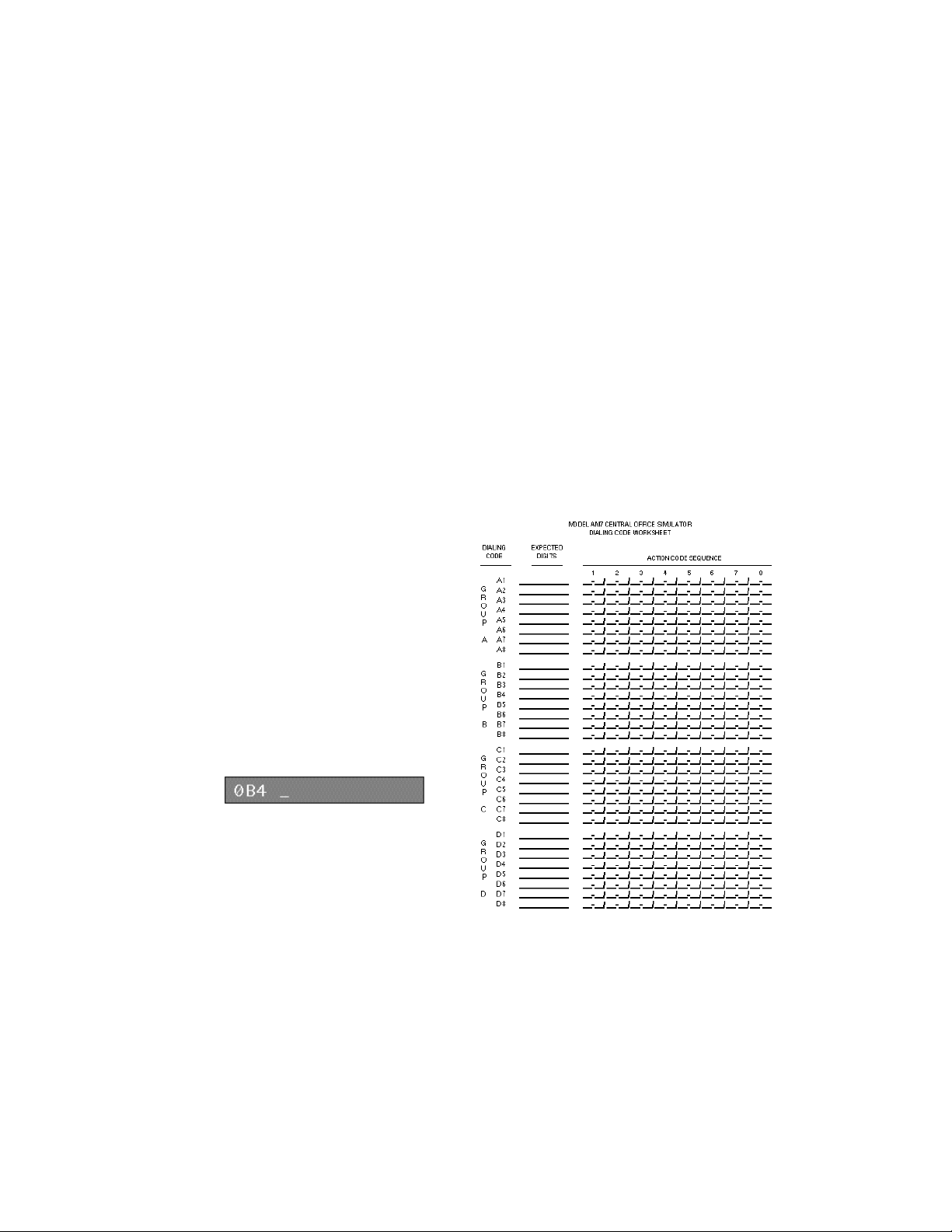
System Setup and Programming (18-0014) AM7 User's Manual
3.4.1 Dialing Code Programming
A maximum of eight dialing codes can be programmed into each Dialing Code
Group (A-D). The Dialing Code Worksheet is an essential part of dialing code
programming, providing a ready reference of the testing values that have been
entered into the AM7.
In order to enter a Dialing
Code, the type of line (0 for
analog, 1-4 for Spans),
group (A-D) and dialing
code number (1-8) must be
entered. If, as an example,
it is necessary to enter
information into Dialing
Code 4 of Group B of an
analog line, press SEL, type
in 0B4, and press Enter.
The display will show
"0B4" followed by a
blinking cursor. This is a
prompt requesting the entry
of up to 12 (or more) digits
that may be expected by the
AM7.
Figure 3-1. Dialing Code Worksheet
3.4.1.1 Expected Digit Field
The expected digit field contains a string of digits that must be matched in order
to activate an Action Code sequence.
July, 1997 0014-S03.B_ 127
3-40
Page 82

AM7 User’s Manual (18-0014) System Setup and Programming
Table 3-7. Expected Digit Field Definitions
Character Meaning
0 - 9 Normal dialed digits.
A - D A - D used in tone dialing.
- (Wildcard Digit) Any normal dialed digit filling this position is accepted as a match.
FLASH Hook Flash. On Hook lasting longer than Flash Time, but less than
Disconnect Time.
BLANK End of string.
As an example, the entry 99999-- in the expected digit field indicates that the
AM7 expects to see seven digits; five 9's followed by any two normal dialed
digits. An entry of 123--67 causes the AM7 to expect seven digits; 123 followed
by any two normal dialed digits, followed by 67. An entry of 123 BLANK 456
causes the AM7 to expect three digits; 123, since BLANK ends the expected
digit string.
Special entries are required when the AM7 is required to process MultiFrequency digits. When expecting MF digits, the AM7 must see a "KP" (key
press) digit in the expected digit field before it will accept any MF digits. This
tells the AM7 to get ready to process the MF digits to follow. If a string of MF
digits is not preceded by a KP digit, the MF digits will not be recognized. When
the AM7 receives an "ST" digit, it starts processing the MF digits it has received
and performs the actions designated by them. It doesn't recognize any further
MF digits until another KP digit is received. The type of ST digit programmed
into the expected digit field depends upon the type of ST digit to which the AM7
is required to respond.
Table 3-8. MF Expected Digit Field Definitions
Character Meaning
KP MF receiver enabler. Enter a KP digit by pressing the *([) key on the AM7
keypad. The KP digit is represented by an asterisk on the display.
ST, ST3P, STP,
ST2P
0014-S03.B_ 127 July, 1997
MF receiver disabler. Enter an ST digit by pressing the # (]) key on the AM7
keypad. The ST digit is represented by a pound sign on the display.
3-41
Page 83
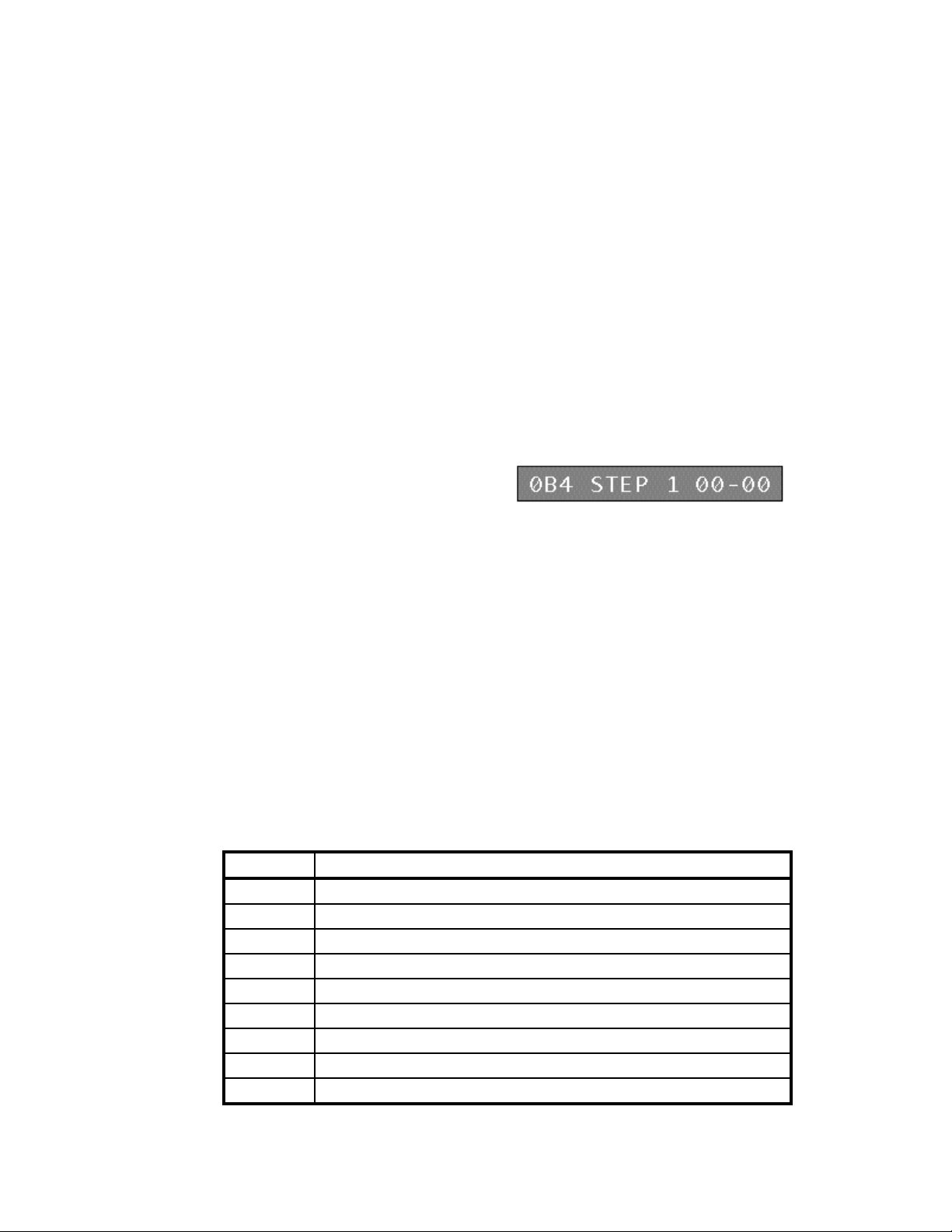
System Setup and Programming (18-0014) AM7 User's Manual
3.4.1.2 Action Code Step Sequences
In order to enter an Action Code Step for a Dialing Code, enter a Dialing Code
such as 0B4. When the prompt for the expected digits appears, enter the digits to
be expected by the AM7. The Action
Code Sequence display is the next to
appear. Enter one of the 27 dialing code actions that can be taken by the AM7.
When the code is typed in and the ETRê key is pressed, the display
automatically moves to Step 2, and continues to move to the next step, when
ETRê is pressed, for up to a maximum of 8 steps. If 00-00 is entered for the last
step, pressing the ETRê key causes the next dialing code entry display (0B5) to
appear. If the ETRè key is pressed after the data for the Dialing Code's (0B4)
step is entered, the same step's display for the next Dialing Code (0B5) appears.
If SHIFT is pressed, then the ETRé key is pressed, the Dialing Code's step is
entered and the display returns to the previous step entered.
The AM7 is shipped from Ameritec with a factory default Dialing Code expected
digit program of 99999--. When the number 99999 is dialed, followed by an
installed line's number (01-20), the AM7 responds by applying ringing to the line
number dialed, and ringback to the incoming line. This default setting provides a
convenient quick check of AM7 operation.
Table 3-9. Action Code Definitions
Action Code Action to be Taken
00-00 No action (end of Action Code Sequence).
01-nn Wait for nn seconds before going to the next programmed step.
02-nn Provide ringback for nn seconds.
03-nn Provide reorder for nn seconds.
04-nn Provide line busy for nn seconds.
05-nn Provide dial tone for nn seconds.
06-00 Provide dial tone until a digit is received.
07-nn Send confirming tone for nn seconds.
08-nn Send digital milliwatt (1000Hz @ 0.0dBm) for nn seconds.
July, 1997 0014-S03.B_ 127
3-42
Page 84

AM7 User’s Manual (18-0014) System Setup and Programming
Action Code Action to be Taken
09-nn Setup call from incoming port to outgoing port. The outgoing port is selected by
the last two dialed digits. If the outgoing port is idle, apply ringback to the
incoming port, apply ringing and detect answer by outgoing port. Answer must
be by a device, such as a modem, telephone, Bulk Call Generator, etc. The
answer is detected by the AM7 and ringback ceases. A speech path and
supervisory channel is established.
10-nn Setup call from incoming port to the outgoing ports of one of up to 8 hunt groups.
The group is selected by the last dialed digit. If nn = 00, the group is selected by
the last dialed digit in the expected digits entry. If nn = 01-08, the call is directed
to the first available port within that hunt group.
11-00 Generate a wink. If Loop/Gnd Start, the polarity is reversed during the Wink. If
E&M, the M lead is true during the Wink.
12-00 Provide Answer Supervision. If Loop/Gnd Start, the polarity is reversed during
Answer Supervision. If E&M, the M lead is true during Answer Supervision.
13-00 Remove Answer Supervision.
14-00 Send 400Hz for nn seconds.
15-00 Send 400Hz until a digit is received.
16-00
SIT Tones
16-01 Send Vacant Code SIT sequence: 980Hz for 380ms, 1370Hz for 275ms, and
16-02 Send No Circuit-BOC SIT sequence: 980Hz for 380ms, 1430Hz for 380ms, and
16-03 Send Intercept SIT sequence: 910Hz for 275ms, 1370Hz for 275ms, and 1780Hz
16-04 Send Reorder-BOC SIT sequence: 910Hz for 275ms, 1430Hz for 380ms, and
16-05 Send Reorder-Carrier SIT sequence: 980Hz for 275ms, 1370Hz for 380ms, and
16-06 Send No Circuit-Carrier SIT sequence: 910Hz for 380ms, 1370Hz for 380ms,
17-00 Ignore dialed digits.
There are 6 sets of Special Information Tones (SIT), provided by the AM7 to
simulate what a caller hears, NOT to cause a switch to react. SIT tones may be
used for number not in service, number changed, circuit busy, etc.
1780Hz for 380ms.
1780Hz for 380ms.
for 380ms.
1780Hz for 380ms.
1780Hz for 380ms.
and 1780Hz for 380ms.
0014-S03.B_ 127 July, 1997
3-43
Page 85

System Setup and Programming (18-0014) AM7 User's Manual
Action Code Action to be Taken
18-00 Accept dialed digits
19-nn Span 1 - corresponds to 09-nn for Analog lines.
20-nn Span 2 - corresponds to 09-nn for Analog lines.
21-nn Span 3 - corresponds to 09-nn for Analog lines.
22-nn Span 4 - corresponds to 09-nn for Analog lines.
23-00 Release PCM/DLC Tone Receiver.
24-00 Release Tone Analyzer.
25-00 Release Dial Pulse Analyzer.
26-nn Attach PCM/DLC Tone Receiver. 00 = Attach Tone Receiver programmed for
the line. 01 = Attach Touch Tone Receiver. 02 = Attach MF Receiver. Do not
use "02" for DLC channels.
Action Codes 19 - 22 switch calls from an incoming port to an outgoing port,
apply ringing, return ringback, detect answers and establish speech and
supervisory paths. For example, 20-13 means for the call to be directed to
Channel 13 of Span 2.
July, 1997 0014-S03.B_ 127
3-44
Page 86

AM7 User’s Manual (18-0014) Programming Examples and Tests
4. PROGRAMMING EXAMPLES AND TESTS
AM7 Dialing Code programming examples and switching and test applications
are described in this section.
4.1 Dialing Code Programming
The AM7 Central Office Simulator Dialing Code Worksheet (shown on the
following page) is an essential part of the AM7 programming, especially for
those just beginning to understand the power of the unit.
Note that the Dialing Code Worksheet is broken down into four basic sections,
each representing one of the four Dialing Code Groups. Note also that the
worksheet is filled out with two factory default numbers: 99999-- and *99999--#.
4.1.1 Analog Line Programming
An expected number sequence of 99999-- means that the AM7 will respond with
ringing to a line number when it recognizes 99999 plus two digits. Since the
factory default is programmed with "--" (the "Match Any Digit" or "Don't Care"
character, any two digits can be appended to the expected digits of 99999. Thus
if 99999 plus 12 is dialed, the AM7 will apply ringing to line "12" if it is
installed.
4.1.2 Multi-Frequency (MF) Programming
When expecting MF digits, the AM7 must see a "KP" digit before it will accept
the expected digits in the MF dialing code. A KP digit acts like a switch to
enable an MF receiver. If a series of MF digits is not preceded by a KP digit, the
AM7 will not recognize the MF digits.
To enter a KP digit into the expected digit field, press the *([) key on the AM7's
program keyboard, or enter an "*" (asterisk) from the terminal keyboard. On the
display, the KP digit appears as an "*" (asterisk).
0014-S04.B_ 115 July, 1997
4-1
Page 87
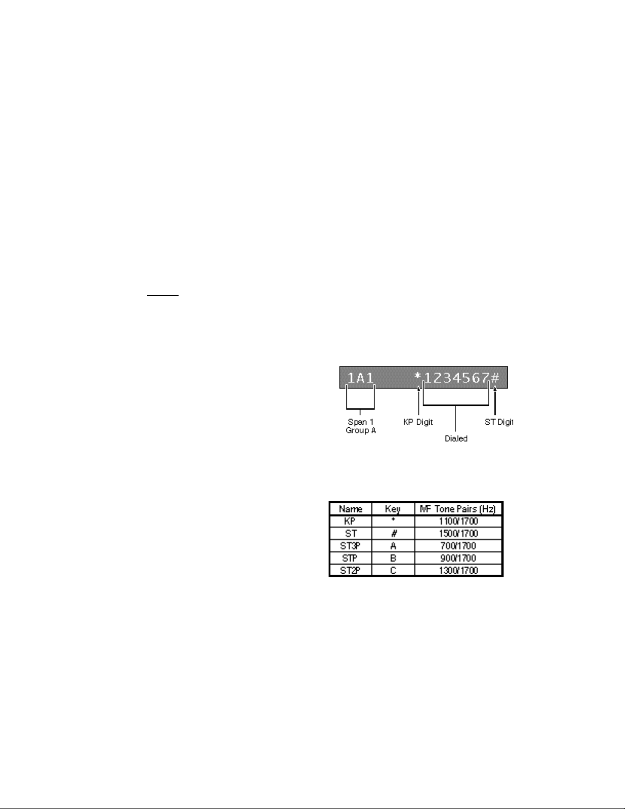
Programming Examples and Tests (18-0014) AM7 User's Manual
Also, depending upon the application, it may be necessary to enter an "ST" digit
after the expected digits in the MF dialing code. An ST digit acts like a switch to
disable an MF receiver. When the AM7 receives an ST digit, it no longer
recognizes MF digits until another KP digit is received.
To enter an ST digit in the expected digit field, press the #(]) key on the AM7's
program keyboard, or enter a "#" (pound) from the terminal keyboard. On the
display, the ST digit appears as an "#" (pound).
A expected digit field is entered for an
MF dialing code by keying in the Span
and Group number (1A1), a KP digit
(*) to enable the MF receiver, the
expected MF digits (1234567), and an
ST digit (#) to disable the MF receiver.
The AM7 doesn't require a KP digit when expecting DTMF (Touch Tone) digits.
Table 4-1. KP/ST Digit Tone Pairs
There are four (4) possible digits
that the AM7 will recognize as an
ST digit. The KP and the four (4)
ST digits are listed along with the
frequencies of the tone pairs.
4.2 Programming Examples
The following AM7 programming examples show the Dialing Code Worksheet
completed to match the example used.
• PBX Station Calling a Central Office Milliwatt (Test Tone) Source
• Simulation of a Telephone Company Central Office Used in Switching Calls
Generated by Autodial Modems Located at a Remote Site into a Computer
Center's Auto Answer Modem(s)
• AM7 Accommodation of an Expected Dialed Digit String Longer than 12
Digits
July, 1997 0014-S04.B_ 115
4-2
Page 88

AM7 User’s Manual (18-0014) Programming Examples and Tests
Figure 4-1. Dialing Code Worksheet
0014-S04.B_ 115 July, 1997
4-3
Page 89
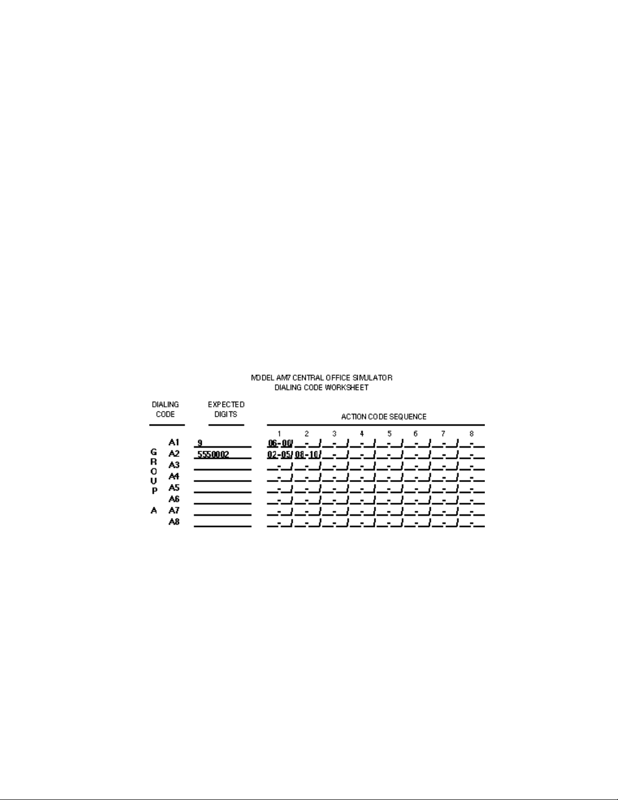
Programming Examples and Tests (18-0014) AM7 User's Manual
4.2.1 PBX Station Calling a Test Tone Source
The first example is programming the AM7 to respond to a PBX station calling a
Central Office Milliwatt (test tone) source. This test is useful in determining the
ability of the device under test to dial the correct digits and receive a test tone.
The loss of frequency caused by the device under test (PBX) can then be
measured. The sequence of events, as reflected on the following worksheet
section, is as follows:
Figure 4-2. PBX Station Calling a Test Tone Source
1. Station Goes Off Hook.
The AM7 provides a dial tone after a programmed delay of from 00 - 99 seconds.
Remember that the dial tone delay is set up when Line Setup parameters are
programmed.
2. PBX Station Dials a "9".
The AM7 waits for the expected digit "9", and then provides a second dial tone
until any other digit is received. Action Code 06-00 provides the dial tone until a
digit is received.
July, 1997 0014-S04.B_ 115
4-4
Page 90
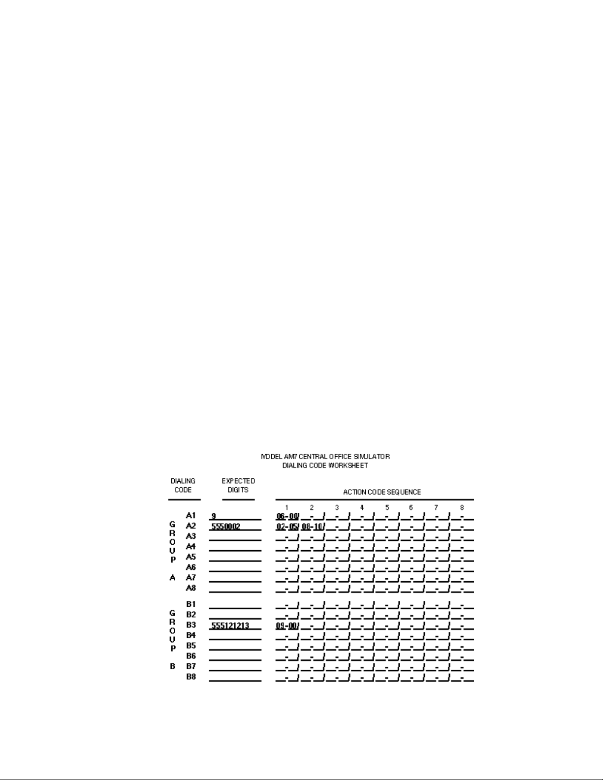
AM7 User’s Manual (18-0014) Programming Examples and Tests
3. PBX Station Waits for a Second Dial Tone and Dials Any Programmed
Milliwatt Telephone Number (5550002).
The AM7 waits for the expected digits 5550002. Once received, the AM7 is
programmed to transmit a Milliwatt test tone (1000Hz at 0.0dBm) for 10
seconds. Action Code 02-05 provides a ringback for 5 seconds. Action Code 0810 generates the digital milliwatt, which is 1000Hz at 0.0dBm, for 10 seconds.
The PBX Station receives a 1000Hz tone for 10 seconds.
4.2.2 Central Office Modem Switching
The second example is to illustrate how the AM7 can be programmed to simulate
a telephone company central office used in switching calls generated by autodial
modems located at a remote site into a computer center's auto answer modem(s).
The sequence of events, as reflected on the following worksheet section, is as
follows:
Figure 4-3. Central Office Modem Switching
0014-S04.B_ 115 July, 1997
4-5
Page 91

Programming Examples and Tests (18-0014) AM7 User's Manual
1. Autodial Modem Goes Off Hook.
The AM7 provides a dial tone after a programmed delay of from 00 - 99 seconds.
Remember that the dial tone delay is set up when Line Setup parameters are
programmed. If the application is to simulate a modem served by a PBX where a
second dial tone is used, the dialing code and step sequences in the previous
example can be used.
2. Modem Dials Simulated Computer Center Number (5551212 + 13).
The AM7 waits for the expected digits 555121213. If there is a match, the AM7
proceeds to the programmed step sequences. Remember that if the AM7 doesn't
match the expected digits, it will generate a reorder signal after 15 seconds. In
this example, the unit has been programmed to setup a call from the incoming
port to the selected outgoing port. The outgoing port number is "13" because
Action Code 09-00 was selected.
Action Code 09-00 means that the last two digits of the expected digits represent
the outgoing port number to which the call is to be directed. Therefore, a call is
set up from the incoming port to port number 13. Ringing is provided to the
outgoing port and ringback is provided to the incoming port.
3. The Modem Simulating the Central Computer Site Attached to Port #13
Receives Ringing, Answers the Call, and Generates It's Answerback
Tone.
The AM7 detects the answer by outgoing port #13 and establishes a data
communications path.
4. The Two Modems, Now Connected Through the AM7 Central Office
Simulator, Can Exchange Data Communications or be Disconnected.
July, 1997 0014-S04.B_ 115
4-6
Page 92
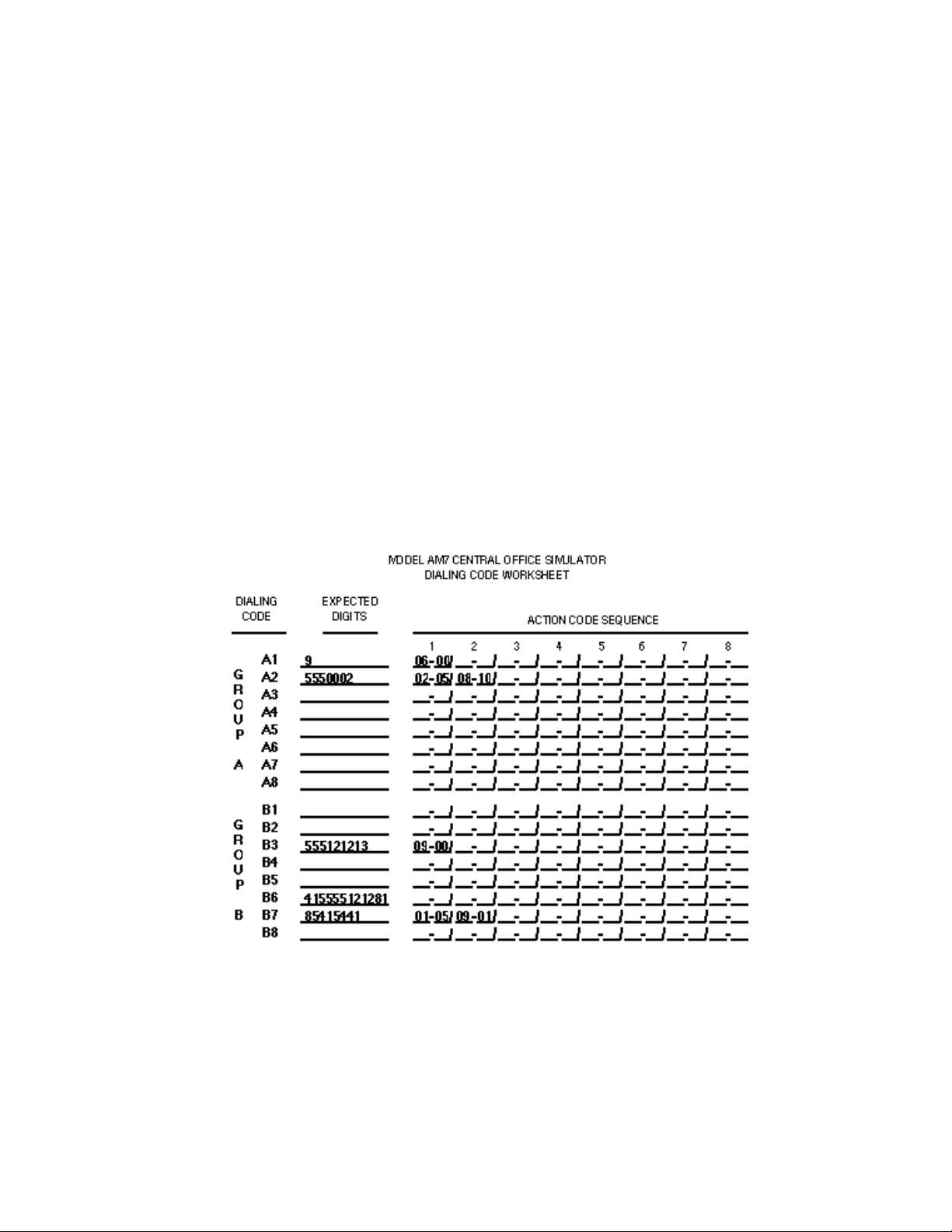
AM7 User’s Manual (18-0014) Programming Examples and Tests
4.2.3 Expected Digits in Excess of 12 Digits
The third example examines how an expected dialed digit string longer than 12
digits can be accommodated by the AM7. Possible applications for programming
the unit to act upon long digit strings would be non-equal access, central office
inter-machine trunk testing, ANI simulation, etc. The sequence of events, as
reflected on the following worksheet section, is as follows:
Figure 4-4. Expected Dialing Code Longer than 12 Digits
1. The Device Under Test Goes Off Hook.
The AM7 provides a dial tone after a programmed delay of from 00 - 99 seconds.
Remember that the dial tone delay is set up when Line Setup parameters are
programmed.
0014-S04.B_ 115 July, 1997
4-7
Page 93

Programming Examples and Tests (18-0014) AM7 User's Manual
2. The Device Under Test Dials the String of Digits. The Following Digits
are Dialed Simulating a Calling and Called Number in a Non-equal
Access Transmission.
The Called Party's digits are 4155551212, while the Calling Party's digits are
818-541-5441.
The AM7 decodes the expected digits 41555512128185415441. The first twelve
digits are received as expected by the AM7. Once decoded, the unit determines
that there are no Action Codes associated with the first twelve digits, so no action
is taken at this time. The AM7 automatically readies itself to decode additional
incoming digits.
As a result, the incoming digits 415555121281 are the expected digits for the first
portion of the dialing sequence. The balance of the incoming digits 85415441
are in the next code's Expected Digits field. The AM7 decodes the digits and
examines the programmed step sequences. The first example step sequence used
is 01-05, which causes the AM7 to wait for 5 seconds before proceeding to the
next step.
Step sequence 09-01 directs the call to line "01", applies ringback to the
incoming port, detects the answer by the outgoing port (port 01), and establishes
a speech and supervisory path through the AM7.
4.3 Switching and Test Applications
There are numerous applications in which the Ameritec Model AM7 Central
Office Simulator can provide switching and test functions. Since the AM7 is a
20-line electronic non-blocking programmable switch, it can be configured to
meet a wide variety of test applications. The AM7 can be used as a serving
central office, toll office, equal access switch, tandem switch, etc.
Several of the possible test applications require an ancillary device to generate
telephone calls into the AM7 Central Office Simulator, such as a rotary dial or
Touch Tone telephone, or autodial modem.
July, 1997 0014-S04.B_ 115
4-8
Page 94
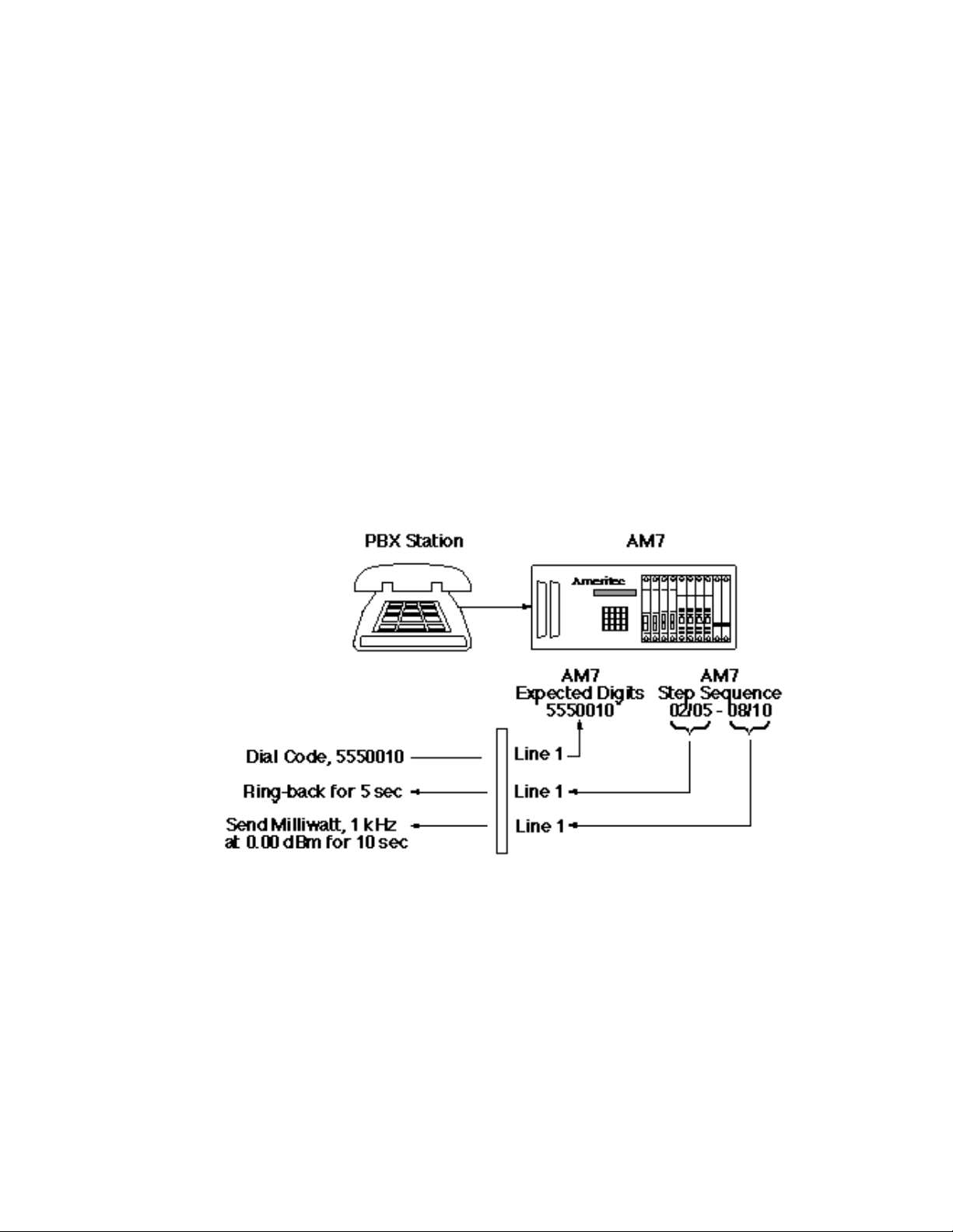
AM7 User’s Manual (18-0014) Programming Examples and Tests
4.3.1 Basic Dialing Test
The signaling output of dial pulse or DTMF telephones, or devices such as
autodial modems, PBX's, etc., can be tested by simply connecting the devices to
the AM7, without the need for installing expensive telephone lines for test
purposes.
Figure 4-5. Basic Dialing Test
Since the AM7 is a 20-line electronic switch, 20 devices can be connected, 10 for
outgoing calls and 10 for incoming calls, or all 20 lines for incoming calls. Line
and System Setup and Programming, discussed in Section 3, provides a detailed
description of how the AM7 can be programmed to react to incoming dialed
digits.
0014-S04.B_ 115 July, 1997
4-9
Page 95

Programming Examples and Tests (18-0014) AM7 User's Manual
A listing of some of the incoming and outgoing call simulation features of the
AM7 is shown below:
Incoming:
• Detects ring ground and provides tip ground for ground start simulation.
• Senses loop closure, or E lead seizure.
• Provides dial tone, or wink on E&M.
• Decodes and analyzes dial pulse digits and optionally analyzes and reports
the level, frequency and timing of DTMF and MF signals.
• Confirms expected digits and performs specified actions.
• Senses idle (disconnect), and prepares for a new call.
Outgoing:
• Triggered by decoding expected digits and executing programmed step
sequences.
• Applies ringing voltage to tip and ring, or sets the M lead true on the E&M
lead on the outgoing port.
• Applies a ringback tone to the incoming port.
• Waits for a ring trip, or E lead true on the E&M lead on the outgoing port.
• Establishes a speech and supervisory path between incoming and outgoing
ports.
• Waits for the incoming port to release the connection.
4.3.2 Autodial Modem Test
The call signaling capability and accuracy of autodial modems can easily be
tested by connecting up to 20 modems to the AM7. The incoming and outgoing
call simulation modes described in the Basic Dialing Test are applicable to
autodial modem testing.
July, 1997 0014-S04.B_ 115
4-10
Page 96
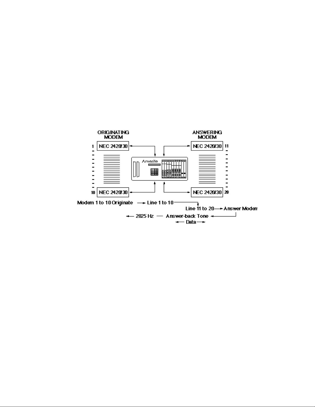
AM7 User’s Manual (18-0014) Programming Examples and Tests
Figure 4-6. Autodial Modem Test
Telephone numbers programmed into the autodial modems which emulate the
remote user can be generated through the AM7. Decoded calls are generated to
receiving modems that are emulating host computer sites. The receiving
modems' answerback tones are generated through the speech and supervisory
paths established in the AM7.
The AM7 can simulate a number of conditions against which an autodial modem
can effectively be tested. Some examples are:
• Dial Tone
• Dial Tone Delay
• Second Dial Tone
• Line Busy
• Reorder
• Delays in Call Progress
• Reaction to Answerback Tone
0014-S04.B_ 115 July, 1997
4-11
Page 97

AM7 User’s Manual (18-0014) Reports
5. REPORTS
The AM7 provides a variety of reports that are dependent upon selectable
options. The reports are transmitted across an RS232C interface, requiring the
connection of a compatible asynchronous serial ASCII terminal, or a modem and
remote terminal. Reports are generated in a serial ASCII format and can be
printed on any compatible ASCII printer, or displayed on any compatible CRT
device. A PC can be used as the terminal device. This allows report information
to be written directly to a floppy or hard disk for storage or statistical analysis.
Reports can be generated either automatically or manually (using Special
Function selections).
5.1 Automatic Reports
The Power Status report is automatic and not selectable. Three Automatic Unit
Data Register reports (Data Readout, Dial Pulse, and Tone Dial) are selected for
generation during System Setup and Programming. The Dialing Code Error
report is selected for generation during Line Setup and Programming. The
following five reports can be generated automatically:
• Power ON and Power OFF- Automatic - No prompt response required
• Data Readout Report- YES (1) to Auto Print prompt
• Dial Pulse Report- YES (1) to Dial Pulse Report prompt
• Tone Dial Report- YES (1) to Tone Dial Report prompt
• Dialing Code Error Report- YES (1) to Dial Code Report prompt
5.1.1 Power ON and Power OFF Report
The Power ON and Power OFF Report is generated every time the AM7 is turned
ON or OFF. Each event is time stamped.
POWER OFF AT: 06:56 05/14/97 POWER ON AT: 06:56 05/14/97
Figure 5-1. Power ON and Power OFF Report
0014-S05.B_126 July, 1997
5-1
Page 98

Reports (18-0014) AM7 User's Manual
5.1.2 Data Readout Report
When automatic printouts are selected, the Data Readout Report is generated
every hour, on the hour. The Data Readout Report provides the Data Code
Register status for each of the lines installed in the AM7. The report includes the
total number of attempts (incoming Off Hooks), Dialing Code matches (A1-A8,
B1-B8, C1-C8, or D1-D8) and calls where there was no code match with the
expected digits.
DATA READOUT 06:54 05/14/97
LINE ATT CODE1 CODE2 CODE3 CODE4 CODE5 CODE6 CODE7 CODE8 NOCODE
003 00000 00000 00000 00000 00000 00000 00000 00000 00000 00000
004 18353 00875 17480 00875 17480 17480 00875 17480 00000 00873
005 00000 00000 00000 00000 00000 00000 00000 00000 00000 00000
TOTL 018353 000875 017480 000875 017480 017480 000875 017480 000000 000873
Figure 5-2. Data Readout Report
When a Data Readout Report is generated for a T1 Span, additional information
is contained in both the top and bottom of the printout. The Bipolar Violations
(BPV), Frame Slips (SLIP), Framing Errors (FERR), and Cyclical Redundancy
Check Errors (CRC) are provided for the selected Span.
At the end of the printout, the "TONE RECEIVER TRAFFIC DATA" indicates
the number of MF and Touch Tone (TT) "RECEIVER OVERFLOWS" (no
receiver of designated type available when first requested.
"ALL RECEIVERS BUSY USAGE" provides the total counts of the number of
times receiver groups were busy at the time of sampling.
• When the AM7 is reset, all counters are set to 00000.
• Each group of each Receiver Card is sampled every 10 seconds.
• If all 3 or 4 receivers are busy when the group is sampled, the counter for that
group is incremented.
• A running total is kept from the time of the last reset.
The "SLOT" indicates the card cage slot location of the Receiver Card. The lefthand five digits indicate Receiver Group "A" all-busy counts. The right-hand five
digits indicate Receiver Group "B" all-busy counts.
July, 1997 0014-S05.B_126
5-2
Page 99

AM7 User’s Manual (18-0014) Reports
DATA READOUT 06:54 05/14/97
SPAN: 1 BPV= 00000 SLIP= 00000 FERR= 00000 CRC= 00000
LINE ATT CODE1 CODE2 CODE3 CODE4 CODE5 CODE6 CODE7 CODE8 NOCODE
101 00000 00000 00000 00000 00000 00000 00000 00000 00000 00000
102 00000 00000 00000 00000 00000 00000 00000 00000 00000 00000
103 00000 00000 00000 00000 00000 00000 00000 00000 00000 00000
104 00000 00000 00000 00000 00000 00000 00000 00000 00000 00000
105 00000 00000 00000 00000 00000 00000 00000 00000 00000 00000
106 00000 00000 00000 00000 00000 00000 00000 00000 00000 00000
107 00000 00000 00000 00000 00000 00000 00000 00000 00000 00000
108 00000 00000 00000 00000 00000 00000 00000 00000 00000 00000
109 00000 00000 00000 00000 00000 00000 00000 00000 00000 00000
110 00000 00000 00000 00000 00000 00000 00000 00000 00000 00000
111 00000 00000 00000 00000 00000 00000 00000 00000 00000 00000
112 00000 00000 00000 00000 00000 00000 00000 00000 00000 00000
113 00000 00000 00000 00000 00000 00000 00000 00000 00000 00000
114 00000 00000 00000 00000 00000 00000 00000 00000 00000 00000
115 00000 00000 00000 00000 00000 00000 00000 00000 00000 00000
116 00000 00000 00000 00000 00000 00000 00000 00000 00000 00000
117 00000 00000 00000 00000 00000 00000 00000 00000 00000 00000
118 00000 00000 00000 00000 00000 00000 00000 00000 00000 00000
119 00000 00000 00000 00000 00000 00000 00000 00000 00000 00000
120 00000 00000 00000 00000 00000 00000 00000 00000 00000 00000
121 00000 00000 00000 00000 00000 00000 00000 00000 00000 00000
122 00000 00000 00000 00000 00000 00000 00000 00000 00000 00000
123 00000 00000 00000 00000 00000 00000 00000 00000 00000 00000
124 00000 00000 00000 00000 00000 00000 00000 00000 00000 00000
TOTL 000000 000000 000000 000000 000000 000000 000000 000000 000000 000000
TONE RECEIVER TRAFFIC DATA
RECEIVER OVERFLOWS: MF= 00000 TT= 00000
ALL RECEIVERS BUSY USAGE
SLOT
009 00000 00000
Figure 5-3. Data Readout Report (T1 Span 1)
0014-S05.B_126 July, 1997
5-3
Page 100

Reports (18-0014) AM7 User's Manual
5.1.3 Dial Pulse Report
The Dial Pulse Report consists of the
speed, percent break, and interdigit
timing. The report is issued for either
ALL digits decoded by the AM7, or only
for those where the selected parameter
thresholds have been exceeded.
This report can be assigned to a specific
line, or randomly assigned by the AM7
to the next busy line.
5.1.4 Tone Dial Report
When the Tone Dial Report is selected, and automatic reports are selected, a
Tone Dial Report is generated for a line.
The Tone Dial Report consists of the LO and HI Band frequencies, percent of
frequency deviation, frequency levels, twist, and ON and OFF (interdigit) times.
The report is issued for either ALL digits decoded by the AM7, or only for those
where the selected parameter thresholds have been exceeded.
This report can be assigned to a specific line, or randomly assigned by the AM7
to the next busy line.
TT DIAL REPORT 06:59 05/14/97
LINE 004 - ALL DIGITS
LOW-BAND HIGH-BAND TWST OFF ON
FREQ DEV LEVEL FREQ DEV LEVEL TIME TIME
(Hz) (%) (dBm) (Hz) (%) (dBm) (dB) (mS) (mS)
9 0852 0.0 -09 1476 -0.1 -09 +00 1047 0059
2 0697 0.0 -09 1336 0.0 -09 +00 0061 0060
3 0697 0.0 -09 1476 -0.1 -09 +00 0060 0060
4 0770 0.0 -09 1209 0.0 -09 +00 0060 0060
5 0770 0.0 -09 1336 0.0 -10 -01 0060 0060
1 0697 0.0 -09 1209 0.0 -09 +00 0641 0061
2 0697 0.0 -09 1336 0.0 -09 +00 0059 0060
8 0852 0.0 -09 1336 0.0 -09 +00 0060 0060
. 1000 ---* -22* ---- --- -- -- 0079 1001
Figure 5-5. Tone Dial Report
PULSE DIAL REPORT 07:01 05/14/97
LINE 004 - ALL DIGITS
SPEED BREAK ID-TIME
9 10.0 60% --2 10.0 60% 600ms
3 10.0 60% 600ms
4 10.0 60% 600ms
5 10.0 60% 600ms
1 ---- -- ---
Figure 5-4. Dial Pulse Report
July, 1997 0014-S05.B_126
5-4
 Loading...