

Page 1
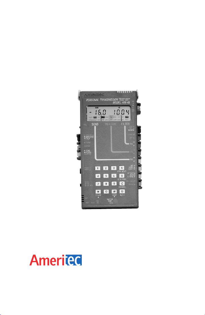
Models AM-48 and AM-48E
Personal Transmission
Test Set
INSTRUCTION MANUAL
Page 2

Models AM-48 and AM-48E
Personal Transmission
Test Set
Instruction Manual
February 4, 2000
Technical Data Subject to
Change without Notice
760 Arrow Grand Circle
Covina, CA 91722 USA
TEL 626.915.5441
FAX 626.915.7181
www.ameritec.com
For extra copies of
this manual, order
Part No. 18-0015 © 2000 Ameritec Corporation
Page 3
Record of Revisions
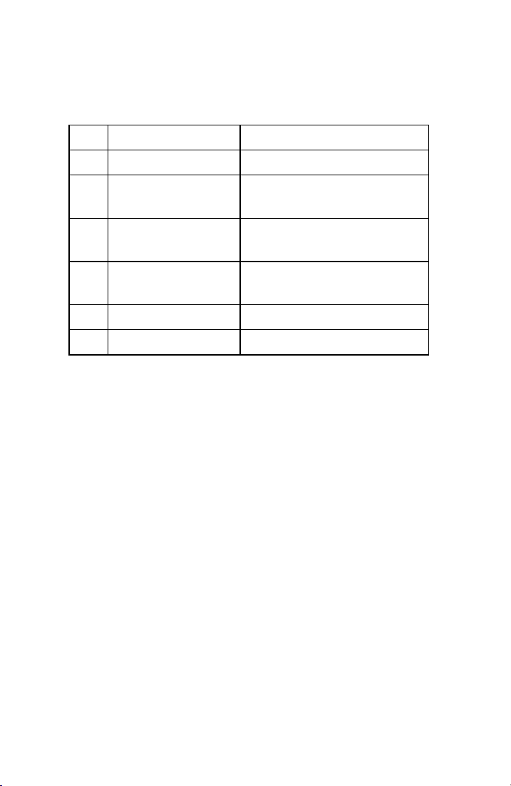
A September 1992 Initial Release.
B January 28, 1998 Minor Update Changes.
C October 2, 1998 Changed Generator
Accuracy Specs.
C1 October 9, 1999 Changed Distortion
specification on 1-6.
D February 4, 2000 Reformatted Manual to
provide new soft copy.
E January 19, 2004 Made a Better PDF
F April 19, 2004 Option
0015-TPG
ii
Page 4

AM-48 Test Set (18-0015) Table of Contents
Table of Contents
1. INTRODUCTION ......................................................................................1-1
1.1 Manual Overview............................................................................... 1-1
1.2 General Description........................................................................... 1-2
1.3 AM-48 Technical Specifications........................................................1-4
1.4 AM-48E Technical Specifications....................................................1-11
2. RECEIVING AND UNPACKING.............................................................. 2-1
2.1 Introduction ........................................................................................2-1
2.2 Inspection when Received ................................................................2-1
2.3 Verification of Contents ..................................................................... 2-1
3. PHYSICAL & FUNCTIONAL DESCRIPTION......................................... 3-1
3.1 Introduction ........................................................................................3-1
3.2 General ..............................................................................................3-1
3.3 Component Location..........................................................................3-2
3.4 Connectors and Cables..................................................................... 3-3
3.5 Switches............................................................................................. 3-5
3.6 Keyboard.......................................................................................... 3-14
3.7 Display .............................................................................................3-17
3.8 Microphone/Speaker........................................................................3-19
3.9 Hand-Held Printer............................................................................ 3-20
3.10 Impedance Adapter .......................................................................3-24
4. POWER CONSIDERATIONS..................................................................4-1
4.1 General ..............................................................................................4-1
4.2 Battery Compartment ........................................................................4-1
4.3 Battery-Selector Switch.....................................................................4-1
4.4 Battery Installation.............................................................................4-3
4.5 Battery Information ............................................................................ 4-3
4.6 AC Power........................................................................................... 4-4
4.7 Power On/Off Switch .........................................................................4-4
0015-TOC
iii
Page 5

Table of Contents (18-0015) AM-48 Test Set
5. SELF-TEST INSTRUCTIONS.................................................................. 5-1
5.1 General ..............................................................................................5-1
5.2 Self-Test Setup..................................................................................5-1
5.3 Quiet Send Mode............................................................................... 5-4
5.4 Send 1004 Hz....................................................................................5-5
5.5 Send PAR (Peak-to-Average Ratio)..................................................5-7
5.6 Dialing ................................................................................................5-8
5.7 Parameter Values for Send Sweep.................................................5-10
6. CONNECTION AND CONFIGURATION.................................................6-1
6.1 Introduction ........................................................................................6-1
6.2 General ..............................................................................................6-1
6.3 Connectors and Cables..................................................................... 6-2
6.4 600Ω/900Ω Line Termination Impedances......................................6-7
6.5 Impedance Adapter ...........................................................................6-9
6.6 Configurations.................................................................................. 6-10
7. OPERATING INSTRUCTIONS................................................................ 7-1
7.1 Introduction ........................................................................................7-1
7.2 General Instructions and Notes.........................................................7-3
7.3 General Operating Notes...................................................................7-3
7.4 Figure Format .................................................................................... 7-4
7.5 General Switch Setup........................................................................ 7-6
7.6 Multiple Use of Keys.......................................................................... 7-8
7.7 Memory..............................................................................................7-9
7.8 General Procedure to Set New Parameter Values.........................7-12
7.9 Send (Generator) Modes and Parameter Settings......................... 7-13
7.10 Types of Send Signals...................................................................7-13
7.11 Send Quiet.................................................................................... 7-14
7.12 Set Parameters from Quiet Display .............................................7-15
7.13 Send Momentary Variable Tones.................................................7-17
7.14 Send 1004 Hz...............................................................................7-18
7.15 Send Continuous Variable Tone..................................................7-19
iv
0015-TOC
Page 6

AM-48 Test Set (18-0015) Table of Contents
7.16 Send Set of Slope Tones .............................................................7-19
7.17 Send Variable Sweep................................................................... 7-20
7.18 Send PAR Waveform ................................................................... 7-22
7.19 Send Momentary 2713 Hz Tone..................................................7-22
7.20 General Instructions and Notes for MEASURE Modes............... 7-22
7.21 Accuracy of Measurements.......................................................... 7-22
7.22 Absolute and Relative Measurements.........................................7-23
7.23 Special Measurement Requirements........................................... 7-24
7.24 Timed Tests..................................................................................7-26
7.25 MEASURE Modes........................................................................7-27
7.26 Measure Level and Frequency.....................................................7-27
7.27 Measure Noise..............................................................................7-28
7.28 Measure PAR................................................................................7-29
7.29 Measure Impulse Noise................................................................7-29
7.30 Measure Notched Noise............................................................... 7-32
7.31 Measure S/N Ratio .......................................................................7-34
7.32 Measure Phase Jitter....................................................................7-34
7.33 Measure Amplitude Jitter..............................................................7-35
7.34 Measure Transients...................................................................... 7-36
7.35 Miscellaneous Operations............................................................ 7-40
7.36 Store and Recall...........................................................................7-40
7.37 Dialing...........................................................................................7-43
7.38 Talking...........................................................................................7-45
7.39 Printing.......................................................................................... 7-45
7.40 Auto Study Result Save................................................................7-56
7.41 Impedance Adapter Measurement Corrections........................... 7-56
7.42 Auto Calibrate...............................................................................7-59
8. EXPLANATION AND APPLICATION OF MEASUREMENTS...............8-1
8.1 Introduction ........................................................................................8-1
8.2 Units of Measurement .......................................................................8-1
8.3 Level (Loss or Gain) and Frequency.................................................8-4
8.4 Idle Channel Noise ............................................................................ 8-4
0015-TOC
v
Page 7

Table of Contents (18-0015) AM-48 Test Set
8.5 Notched Noise (Noise with Tone) ..................................................... 8-4
8.6 Signal-to-Noise (S/N) Ratio...............................................................8-5
8.7 P/AR Measurements..........................................................................8-6
8.8 Gain Slope .........................................................................................8-8
8.9 Idle Channel Impulse Noise ..............................................................8-9
8.10 Phase Jitter.................................................................................... 8-11
8.11 Amplitude Jitter..............................................................................8-11
8.12 Notched Impulse Noise .................................................................8-12
8.13 Phase Hits......................................................................................8-12
8.14 Gain Hits ........................................................................................8-12
8.15 Dropouts.........................................................................................8-12
9. CIRCUIT DIAGRAMS...............................................................................9-1
9.1 Introduction ........................................................................................9-1
9.2 AM-48 Simplified Block Diagram.......................................................9-1
9.3 Impedance Adapter Schematic.........................................................9-3
10. WARRANTY, SERVICE, AND CALIBRATION ..................................10-1
10.1 Warranty.........................................................................................10-1
10.2 Service Policy ................................................................................10-1
10.3 Calibration Policy........................................................................... 10-1
10.4 Return of Unit.................................................................................10-2
11. GLOSSARY........................................................................................... 11-1
vi
0015-TOC
Page 8

AM-48 Test Set (18-0015) Table of Contents
List of Figures
Figure 3-1. AM-48 Location of Components................................................ 3-3
Figure 3-2. AM-48 Connectors.....................................................................3-4
Figure 3-3. Standard AM-48 Cables ............................................................3-4
Figure 3-4. Optional AM-48 Cables..............................................................3-5
Figure 3-5. AM-48 Switch Identification Numbers .......................................3-6
Figure 3-6. AM-48 Keyboard Identification Numbers ................................ 3-15
Figure 3-7. AM-48 Liquid Crystal Display ..................................................3-18
Figure 3-8. Hand-Held Printer, External View............................................3-22
Figure 3-9. Hand-Held Printer, Internal View............................................. 3-23
Figure 3-10. Impedance Adapter................................................................3-24
Figure 4-1. Battery Installation and Selector Switch.................................... 4-2
Figure 5-1. AM-48 Setup for Self-Test (Looped Back)................................5-2
Figure 5-2. General Switch Setup for Self Test...........................................5-3
Figure 5-3. Quiet Send Mode Self Test........................................................5-4
Figure 5-4. Send 1004 Hz Self Test, Switch Settings..................................5-6
Figure 5-5. Send 1004 Hz Self Test, Displays............................................. 5-7
Figure 5-6. Send PAR (Peak-to-Average Ratio).......................................... 5-8
Figure 5-7. Dialing.......................................................................................5-10
Figure 5-8. Default Parameter Settings for SWEEP Send Mode.............. 5-14
Figure 6-1. 2-Wire AM-48 Line Connections................................................6-3
Figure 6-2. 4-Wire AM-48 Line Connections................................................6-4
Figure 6-3. AM-47 Hand-Held Printer Connection with AC Power..............6-5
Figure 6-4. 4-Wire End-to-End Testing......................................................6-11
Figure 6-5. 4-Wire Testing with Responder...............................................6-13
Figure 6-6. 2-Wire Network Testing with Responders............................... 6-14
Figure 7-1. Parameter Settings from QUIET SEND
Figure 7-2. Parameter Settings from 1004 Hz and VAR Tone Displays ...7-18
0015-TOC
vii
Display.....................7-15
Page 9

Table of Contents (18-0015) AM-48 Test Set
Figure 7-3. Parameter Settings from 3-TONE Slope and
PAR SEND Displays......................................................... 7-20
Figure 7-4. Parameter Settings from SWEEP SEND Display...................7-21
Figure 7-5. L/F, NOISE, and PAR MEASURE Displays............................ 7-28
Figure 7-6. IMPLS MEASURE Displays.....................................................7-32
Figure 7-7. Notched NOISE and S/N Ratio MEASURE Displays .............7-33
Figure 7-8. Phase JTR and Amplitude JTR MEASURE Displays............. 7-35
Figure 7-9. TRANS MEASURE Displays..........................................7-39, 7-40
Figure 7-10. Recall and Store Operations .................................................7-42
Figure 7-11. SEND Printouts...................................................................... 7-52
Figure 7-12. MEASURE Printouts, Absolute Measure Mode.................... 7-54
Figure 7-13. MEASURE Printouts, Relative Measure Mode..................... 7-55
Figure 7-14. Impedance Adapter Correction Value Memory Aid............... 7-58
Figure 7-15. AM-48 Auto Calibrate Prompts..............................................7-60
Figure 8-1. Level and Noise Units of Measurement....................................8-2
Figure 8-2. Impulse Noise Thresholds and Blanking Intervals.................. 8-10
Figure 9-1. Simplified Block Diagram of the AM-48.....................................9-2
Figure 9-2. Schematic Diagram of the Impedance Adapter........................9-4
viii
0015-TOC
Page 10

AM-48 Test Set (18-0015) Table of Contents
List of Tables
Table 1-1. AM-48 General Technical Specifications ...................................1-5
Table 1-2. AM-48 Generator (Send) Technical Specifications.................... 1-6
Table 1-3. AM-48 Receiver (Measure) Technical Specifications................1-8
Table 1-4. AM-48 Power/Physical Technical Specifications .....................1-11
Table 2-1. AM-48 Standard Equipment .......................................................2-2
Table 2-2. AM-48 Optional Equipment ........................................................2-2
Table 3-1. Front Panel/Switches Color Coding............................................3-2
Table 3-2. AM-48 SEND, MEASURE, and FILTER Menus.......................3-19
Table 3-3. AM-47 Hand-Held Printer Technical Specifications................. 3-21
Table 7-1. Setup Requirements for Different Keyboard Applications .........7-8
Table 7-2. Steps for Up and Down Arrow Keys........................................... 7-9
Table 7-3. User-Programmable Parameter Values Stored in Memory.....7-11
Table 7-4. Acceptable Holding Tone Ranges............................................7-25
Table 7-5. Special Measurement Requirements........................................ 7-26
Table 7-6. Setup Requirements for Dialing................................................ 7-44
Table 7-7. MF and DTMF Tone Pairs.........................................................7-44
Table 7-8. Impedance Adapter Correction Values.....................................7-57
Table 8-1. P/AR Requirements of Telephone Lines.................................... 8-6
0015-TOC
ix
Page 11

AM-48 Test Set (18-0015) Introduction
1. INTRODUCTION
1.1 Manual Overview
This instruction manual describes Ameritec Corporation’s AM-48
and AM-48E Personal Transmission Test Sets.
Note: Throughout this manual, all references to the "AM-48" also
apply to the "AM-48E", unless otherwise noted. See ¶1.4
for a summary of the differences between the AM-48 and
the AM-48E.
The other paragraphs in this Introduction section are:
1.2 General Description
1.3 AM-48 Technical Specifications
1.4 AM-48E Technical Specifications
The balance of the manual is divided into the following sections:
2. Receiving and Unpacking
3. Physical and Functional Description
4. Power Considerations
5. Self-Test Instructions
6. Connection and Configuration
7. Operating Instructions
8. Explanation and Application of Measurements
9. Circuit Diagrams
10. Warranty, Service, and Calibration
11. Glossary
Index
0015-S01
1-1
Page 12

Introduction (18-0015) AM-48 Test Set
Note: It is suggested that the foldout at the back of the manual be
extended when using this manual. The FOLDOUT, a front view
of the AM-48, defines the numbers of the switches which are
used to identify the switches throughout this manual.
Glossary . Refer to the Glossary to become familiar with the
terminology used in this manual.
Power . Be sure to read Section 4 and observe the WARNING in ¶4.3
before powering up the AM-48.
Self Test . Perform the Self Test in Section 5 to:
1. confirm that all AM-48 circuits and basic functions are
working properly, and
2. obtain "hands-on" experience with the AM-48 to learn how
the controls operate.
Transmission Measurements . Note that Section 7, Operating
Instructions, gives procedures to
explanation and application of the measurements, see Section 8.
For
perform transmission measurements.
1.2 General Description
Definition and Purpose . In one (1) hand-held unit, the AM-48
provides the field engineer with two (2) instruments:
1. a transmission test set, and
2. a telephone "butt-set".
transmission test set tests the integrity and quality of 2-wire or
The
4-wire voice and data transmission lines by sending selected analog
signals and measuring standard parameters of the received signals.
0015-S011-2
Page 13

AM-48 Test Set (18-0015) Introduction
3
The telephone "butt set" enables the field engineer to dial up and
speak back-and-forth with a field engineer at the far end of the
system. The compact and light-weight AM-48 eliminates the need to
carry multiple, bulky test sets.
Functional Overview
AM-48 can send:
• any frequency from 200 Hz to 20 kHz @ -50 to +10 dBm
• continuous 3-tone slope (404, 1004, 2804 Hz)
• continuous, user-defined, sweep tones
• fixed 1004 Hz
• P/AR waveform
• momentary 2713 Hz for WECO 829 loopback
AM-48 can measure:
• level, -65 to +10.9 dBm (absolute or relative)
• frequency, 0 to 19,999 Hz
• idle channel noise
• noise with tone
• three-level impulse noise
• phase jitter
• gain jitter
• transients (dropouts, phase and gain hits, impulse noise)
• signal-to-noise (S/N) ratio
• peak-to-average ratio (P/AR)
Noise filters provided (each with optional 1010 Hz notch)::
• C-Message (Psophometric for AM-48E)
• 3 kHz
• 15 kHz
• Program (Sound-weighted for AM-48E)
0015-S01
1-
Page 14

Introduction (18-0015) AM-48 Test Set
Other features:
• High impedance bridge, 600 or 900 Ohm termination
• Display prompts help in set-up and testing sequences
• On-board memory can store & recall up to 10 user-defined
test set-ups
• Dials: pulse, DTMF, and MF
• Talk/Listen capability
• Printer interface for hard copy of set-up and test results
• Battery life: Alkaline, 6 to 7 hours; NiCad, 3 to 4 hours
• NiCad batteries can be recharged without removing them
from the unit
Testing Configurations: (For details, see ¶6.6)
There are three (3) basic AM-48 configurations used to test
2-wire/4-wire telephone/data communication lines:
1. End-to-end -- requiring two (2) AM-48 units
2. Loopback
3. Testing with responders
1.3 AM-48 Technical Specifications
AM-48 technical specifications are presented in four (4) parts:
1. General (Table 1-1)
2. Generator (Send) (Table 1-2)
3. Receiver (Measure) (Table 1-3)
4. Power/Physical (Table 1-4)
0015-S011-4
Page 15
AM-48 Test Set (18-0015) Introduction
5
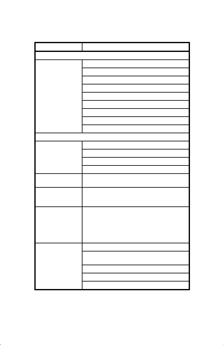
Table 1-1. AM-48 General Technical Specifications
Characteristic Specification
Measurements
Level -65 to +10.9 dBm
Frequency 0 to 19,999 Hz
Noise 10 to 99 dBrn
Notched Noise 10 to 99 dBrn
Signal to Noise 0 to 60 dB
P/AR 0 to 120
Amplitude Jitter 0.0 to 25.0%
Phase Jitter 0.0 to 25.0 degrees
3-Level Impulse Noise Counts from 0 to 9999
Transient Measurements
Dropouts 0 to 9999
Gain Hits 0 to 9999
Phase Hits 0 to 9999
3-Level Impulse Noise Counts from 0 to 9999
Dial Built-in 16 button keypad for dial pulse, DTMF (Touch
Talk Built-in microphone and speaker with push-to-talk
Holding A single line holding circuit is provided for 2-wire
Impedances 600 and 900 ohm.
Tone), or MF dialing.
operation on both 2-wire and 4-wire lines. Earphone
jack for optional earphone.
operation, or the send pair of 4-wire circuits. It
electronically simulates a holding coil with a DC
resistance of approximately 200 ohms. The AC
impedance is high enough to give no more than 0.2 dB
loss at 600 ohm impedance.
Balance > 60 dB below 4 kHz, decreasing 6 dB.octave
above 5 kHz.
Return loss > 30 dB 200-5000 Hz, > 15 dB 5-20 kHz.
DC blocking - 150 Volts.
Bridging impedance > 25 kohms.
0015-S01
1-
Page 16
Introduction (18-0015) AM-48 Test Set
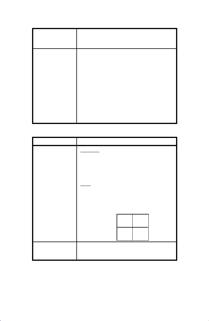
Characteristic Specification
Printer Current loop interface to optional printer for hard copy
of unit setup and measurement results
Store/Recall 10 complete unit setups may be stored by user in
internal nonvolatile memory, and recalled for ease of
repeating frequently-used tests. In addition, the results
of the last impulse or transient study (along with the
associated setups) are stored to nonvolatile memory at
the completion of the study. They are recalled
automatically whenever the unit is turned on.
Also stored in nonvolatile memory are four (4) user-set
parameters (each set from the QUIET mode):
1. Touch Tone/MF Dial Level
2. Power Down Time with momentary power switch
3. Blanking interval for impulse and transient tests
4. 10 user-programmable momentary frequencies
Table 1-2. AM-48 Generator (Send) Technical Specifications
Characteristic Specification
Variable Frequency: 200 Hz to 19,999 Hz in 1 Hz steps.
Frequency may be entered directly via the keypad or
stepped up or down in 10 Hz steps with auto-repeat
steps of 100 Hz (4 steps/second) for fast frequency
slewing. Frequencies are crystal-controlled and
accurate to ±.72 Hz ±.01%.
Level: -50.0 dBm to +10.0 dBm in .1 dB steps. Level
may be entered directly via the keypad or stepped up
or down in .1 dB steps with auto-repeat steps of 1.0 dB
(4 steps/second) for fast level slewing. Level accuracy
is as follows:
+10 dBm
-40 dBm
-50 dBm
200 Hz
±0.2 ±0.5
±0.5 ±1.0
15 kHz 20 kHz
1004 Hz A fixed 1004 Hz holding tone is provided. The
frequency is accurate to ±.025%. Level is the same as
variable.
0015-S011-6
Page 17
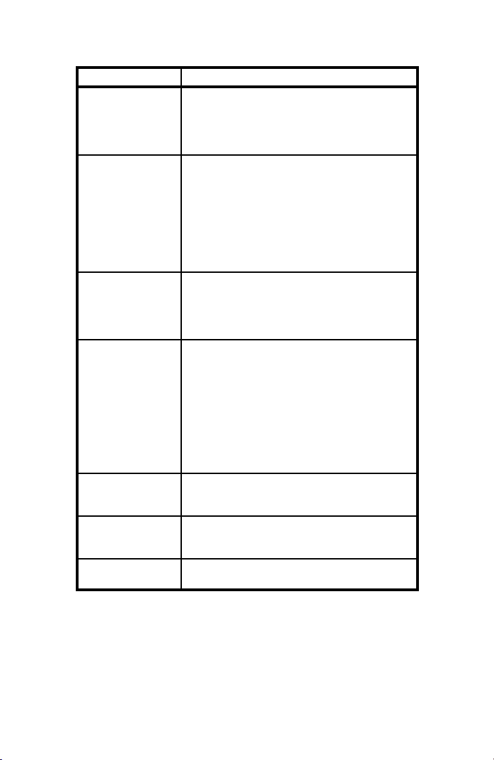
AM-48 Test Set (18-0015) Introduction
Characteristic Specification
3-Tone A three-tone slope frequency mode is provided, which
cycles continuously between 404 Hz, 1004 Hz, and
2804 Hz, giving 5 seconds of each tone. Frequency
accuracy is the same as variable. Level is the same
as variable.
Sweep A programmable frequency sweep generator is
provided. It generates tones continuously from a userspecified START frequency (200 Hz to 19,999 Hz) to a
user-specified STOP frequency (200 Hz to 19,999 Hz),
at a user-specified frequency STEP interval (1 Hz to
19,999 Hz), and at a user-specified step RATE (0.1
second to 19,999 seconds/frequency). Frequency
accuracy is the same as variable. Level is the same
as variable.
PAR A PAR waveform generator is provided, which
generates the 16 simultaneous frequency PAR
waveform per Bell 41009 specifications. The level
may be set from -40.0 dBm to 0.0 dBm, with 0.1 dBm
resolution. Level accuracy is ±0.5 dBm.
Quiet In quiet mode, the line is terminated with a passive
resistance equal to the line impedance. Also, when in
Quiet, one of 10 user-programmable tones may be
momentarily applied to the line by depressing the (0)
thru (9) keys.
Programmable from this mode are (1) Touch Tone dial
level (-50.0 to 7 dBm), (2) Power down Time Off (1 to
255 minutes), (3) Impulse and Transient test Blanking
Interval (1 to 255 ms), and (4) 10 user-programmable
tones for later instant recall.
Aux Tone A momentary pushbutton is provided for the
generation of an auxiliary tone (2713 Hz), used to
activate remote 829-type loopback devices.
SF Skip A Signaling Frequency (SF) Skip mode prevents the
generation of tones between 2450 Hz and 2750 Hz in
variable or sweep modes.
Distortion Total distortion is < -50 dB @ 1004 fixed tone and
< -40 dB @ any other frequency.
0015-S01
1-7
Page 18
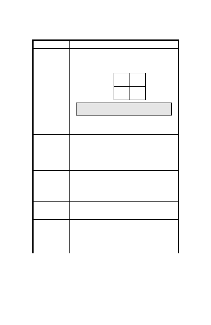
Introduction (18-0015) AM-48 Test Set
Table 1-3. AM-48 Receiver (Measure) Technical Specifications
Characteristic Specification
Level/Freq Level is measured with an average responding detector.
Range is -65.0 to +10.9 dBm with 0.1 dBm resolution.
Accuracy is as follows:
+10 dBm
-40 dBm
-65 dBm
Note: Accuracy is ±0.1 dBm at 1004 Hz from -20
dBm to 0.0 dBm.
Frequency is measured from 200 Hz to 19,999 Hz with an
accuracy of ±.01% ±1 Hz, and a resolution of 1 Hz. Input
level -40 to +10 dBm.
PAR Peak-to-Average Ratio (PAR) is measured from 0 to 120
PAR units to a resolution of 1 PAR unit. Accuracy is ±2
from 30 to 110, ±4 from 0 to 120 over a signal range of -40
to 0 dBm.
PAR signal level is measured from -40 to 0 dBm, with a
resolution of 1 dBm, using an RMS detector.
Noise Noise is measured with an RMS responding detector from
10 to 99 dBrn to 1 dBrn resolution. Accuracy is ±1 dBrn
from 20 to 99 dBrn, and ±2 dBrn from 10 to 20 dBrn.
Weighting Filters are 3 kHz flat, 15 kHz flat, CMSG, and
Program filter.
Notched Noise Notched Noise is the same as noise with the addition of a
1010 Hz notch filter, minimum 50 dB deep from 995 to 1025
Hz.
S/N ratio Signal-to-Noise (S/N) ratio display the ratio of signal
(holding tone) to notched noise. The signal must be -40 to
+10 dBm. The notched noise may be 10 to 70 dBrn. The
S/N ratio may be from 10 to 50 dB. Resolution is 1 dB.
Accuracy is ±1 dB for notched noise 20 to 70 dBrn, and ±2
dB for notched noise from 10 to 20 dBrn.
200 Hz
±0.2 ±0.5
±0.4 ±0.8
15 kHz 20 kHz
0015-S011-8
Page 19
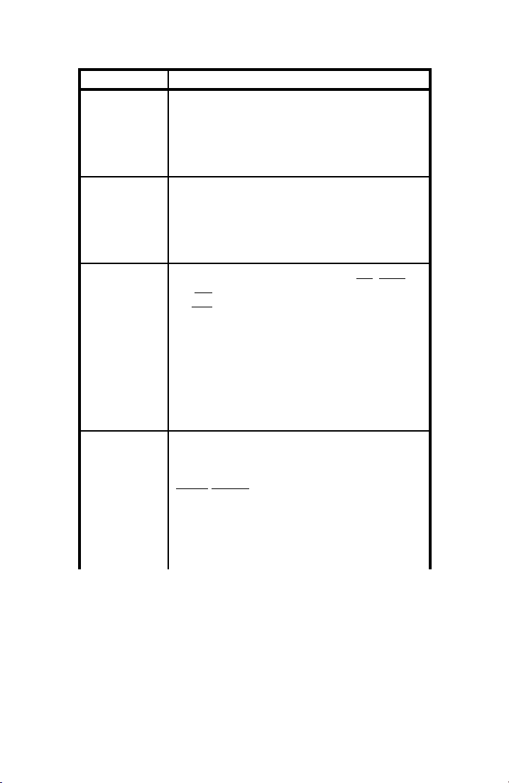
AM-48 Test Set (18-0015) Introduction
9
Characteristic Specification
Amplitude Jitter Displays the incidental amplitude modulation of a holding
Phase Jitter Displays the incidental phase modulation of a holding tone.
Impulse Noise Three (3) noise thresholds are established: Low, Middle,
Transients Counts dropouts, gain hits, phase hits, and 3-level impulse
tone. The holding tone must be -40 to +10 dBm, 990 to
1030 Hz. Amplitude jitter is displayed from 0.0 to 25.0%
with a resolution of .1% and an accuracy of ±.2%, ±5% of
reading.
Weighting filter selection: 20-300 Hz or 4-300 Hz.
The holding tone must be -40 to +10 dBm, 990 to 1030 Hz.
Phase jitter is displayed in degrees from 0.0 to 25.0
degrees with a resolution of .1 degree and an accuracy of
±.2 degree, ±5% of reading.
Weighting filter selection: 20-300 Hz or 4-300 Hz.
and High levels, with an equal interval between them called
the Delta. The maximum High threshold is 105 dBrn for
600 ohm impedance (or 104 dBrn for 900 ohm). The
minimum Low threshold is 30 dBrn. Delta can be 2, 3, 4, or
6 dB. Threshold accuracy: ±1 dB. A user-selected
blanking interval of 1 to 255 ms for each threshold, blocks
further counting of impulses at that threshold.
The study duration timer may be set from .1 minute to
1999.9 minutes in .1 minute steps, or continuous. Each
threshold has a count capacity of 0-9999. Weighting filters
same as noise.
noise with tone. Holding tone must be -40 to +10 dBm, 995
to 1025 Hz
Dropout threshold is -12 dB from the initial level of the
holding tone. A dropout will be counted if the holding tone
drops below the threshold for at least 4 ms ±.5 ms.
Counting of dropouts, gain hits, phase hits, and impulses is
inhibited for a blanking interval which lasts until 1 second
after the holding tone is restored to a level above the
dropout threshold.
0015-S01
1-
Page 20
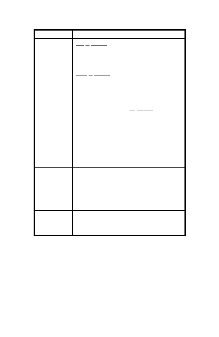
Introduction (18-0015) AM-48 Test Set
Characteristic Specification
Transients
(cont.)
Gain hit threshold can be 2, 3, 4, or 6 dB. A gain hit will be
counted if the level of the holding tone changes up or down
by more than the threshold for at least 4 ms ±.5 ms. A
blanking interval, that is user-set from 1 to 255 ms, blocks
further counting of gain hits.
Phase hit threshold can be 5 to 45 degrees in 1 degree
steps, with an accuracy of ±.5 degrees ±10% of the setting.
A phase hit will be counted if the phase of the holding tone
changes by more than the threshold fro at least 4 ms ±.5
ms. A blanking interval, that is user-set from 1 to 255 ms,
blocks further counting of phase hits.
The three-level impulse noise low threshold can be set from
30 to 110 dBrn with threshold differences of 2, 3, 4, or 6 dB.
Threshold accuracy: ±1 dB. An independent blanking
interval for each threshold, user-set from 1 to 255 ms,
blocks further counting of impulses at that threshold.
The study duration timer may be set from .1 minute to
1999.9 minutes in .1 minute steps, or set to 0 for a
continuous study.
Each transient has a count capacity of 0-9999.
Filters same as noise.
Damping A damp mode reduces the display update rate from
approximately 4 times/second to approximately 2
times/second for reading widely fluctuating measurements.
The same switch, when in <DAMP> position, also changes
the monitoring point of the receive (RCV) monitor speaker
to the output of the auto-range amplifier (significantly
increasing the speaker level).
Term/Bridge When in terminate, the receiver terminates the line in the
selected impedance. When in bridge, the line is bridged by
a high impedance, causing no more than .2 dB loss on a
600 ohm line.
0015-S011-10
Page 21
AM-48 Test Set (18-0015) Introduction
Table 1-4. AM-48 Power/Physical Technical Specifications
Characteristic Specification
Power Four 1.5 VDC "AA" alkaline batteries provide about six
Physical Size: 4.2" (106mm)W x 7.6" (193mm)H x 1.7" (43mm) D.
hours operation. NiCad batteries provide about half the life
of alkaline.
External AC adapter powers unit from 120 VAC and
charges optional NiCad batteries in the unit.
Auto shutoff after last switch actuation is userprogrammable for 0 (no shutoff), or from 1 to 255 minutes.
May be overridden by placing power switch in the <ON>
position. Does not turn itself off while timed study is in
progress.
Weight: 23 oz. with alkaline batteries (slightly less with
NiCad).
Connections to phone line via dual bantam jacks and
RJ11C modular jack.
1.4 AM-48E Technical Specifications
AM-48E is an international version transmission test set which meets
CCITT standards. All specifications for the AM-48 in Tables 1-1
thru 1-4 are identical for the AM-48E, except as described below:
1. Instead of the C-Message
AM-48E has the
Psophometric (PSHO) noise-weighting filter .
See Figures 3-6 and 3-7.
2. Instead of the Program
AM-48E has the
Sound-weighted (SWTD) filter . See Figures
3-6 and 3-7.
3. Instead of the
3TONE slope frequency send mode of 404 Hz,
1004 Hz, and 2804 Hz @ 5 seconds, the AM-48E has a 4-tone
SLOPE frequency send mode of 404 Hz , 1004 Hz , 2004 Hz , and
3004 Hz @ 5 seconds. See Figures 3-6 and 3-7.
(CMSG) noise-weighting filter, the
(PROG) noise-weighting filter, the
0015-S01
1-11
Page 22

Introduction (18-0015) AM-48 Test Set
4. Instead of Signal Frequency (SF) Skip 2450 Hz to 2750 Hz, the
AM-48E has
SF SKIP from 2130 Hz to 2430 Hz .
5. On all noise displays, instead of units of dBrn , the AM-48E
displays the noise in units of
dBm . See ¶8.2 and Figure 8-1 for
definitions and corresponding values of dBrn and dBm units.
0015-S011-12
Page 23

AM-48 Test Set (18-0015) Receiving and Unpacking
2. RECEIVING AND UNPACKING
2.1 Introduction
This section covers procedures to follow when the AM-48 is first
received in its shipping container:
2.2 Inspection when Received
2.3 Verification of Contents
2.2 Inspection when Received
The AM-48 was thoroughly tested and carefully packed before
shipment, and was in good condition when turned over to the carrier
for transport.
The name of the carrier will be noted on the packing slip which
accompanied the shipment.
Upon receipt, thoroughly inspect the outside of the shipping container
for damage. If the container is damaged, and the AM-48 is found to
be damaged or non-operational, immediately contact the carrier and
submit a claim for damages.
Note: To test if the unit is operational, see Section 4 for Power
Considerations and Section 5 for Self-Test Instructions.
2.3 Verification of Contents
After opening and unpacking, use the following equipment lists to
verify that all ordered items have been received. Note that some
items are standard and always included; other items are optional, and
only shipped when specially ordered.
0015-S02
2-1
Page 24
Receiving and Unpacking (18-0015) AM-48 Test Set
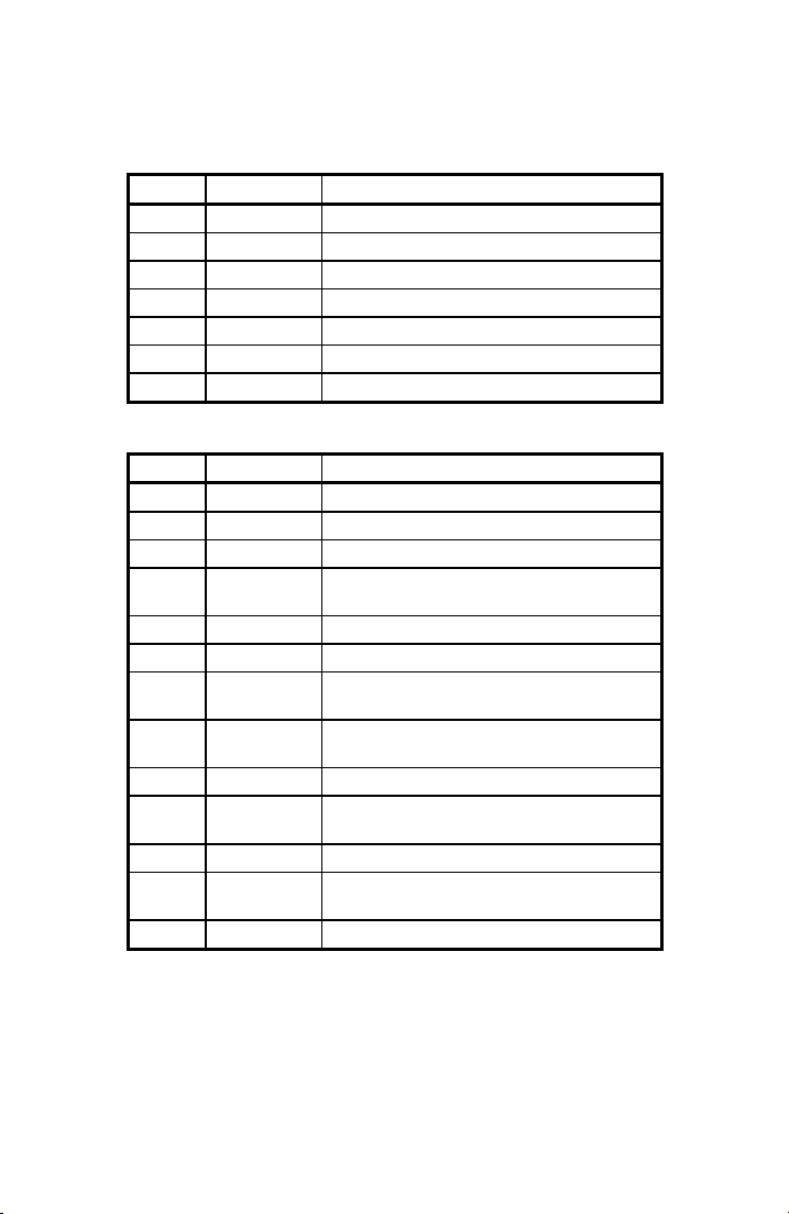
Table 2-1. AM-48 Standard Equipment
Amount Part Number Description
1
4
1
1
1
1
1
AM-48 unit
24-0006 AA-size 1.5 VDC alkaline batteries
48-0049 Modular input cord with minigator clips
82-0005 Earphone
70-0029 AC Adapter
18-0015 AM-48/AM-48E Instruction Manual
87-0009 AC Adapter
Table 2-2. AM-48 Optional Equipment
Amount Part Number Description
1
4
4
1
1
1
1
1
1
1
1
1
1
24-0005 Impedance Adapter (1200, 150, 135, 75 ohms)
24-0006 AA-size alkaline batteries (replacement set)
24-0007 AA-size NiCad (rechargeable) batteries
AM-47 Hand-held printer - includes roll of paper, ribbon
cartridge, and 48-0079 Printer Cable.
26-0014 roll of paper for Hand-held printer
26-0015 ribbon cartridge for Hand-held printer
48-0047 Bantam (M) to Bantam (M) Cable (6') (two
required for 4-wire operation)
48-0048 Bantam (M) to 310 (M) Cable (6') (two required for
4-wire operation)
48-0049 Modular to Minigator Cable (7')
48-0062 Bantam (M) to Minigator Cable (6') (two required
for 4-wire operation)
48-0078 Printer Cable for use with an EIA printer
48-0079 Printer Cable for use with Ameritec Hand-held
printer.
87-0016 AM4 Soft Carrying Case
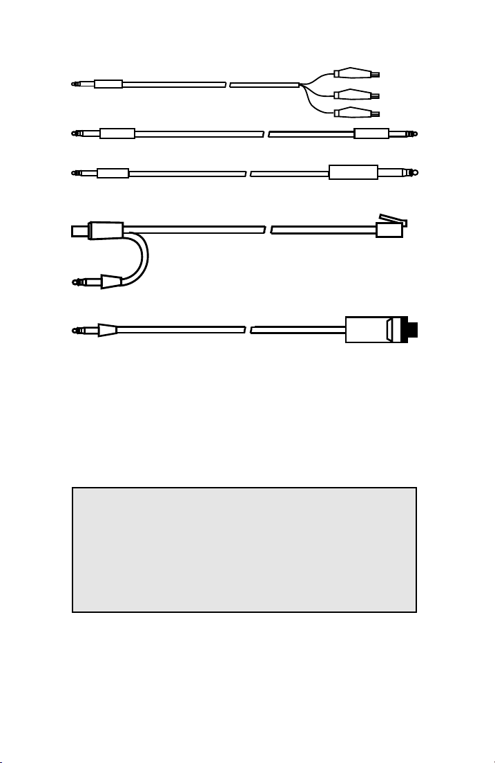
See Figure 3-3 for illustrations of the cables listed in Tables 2-1 and
2-2.
0015-S02
2-2
Page 25

AM-48 Test Set (18-0015) Unit Description
3
3. PHYSICAL & FUNCTIONAL DESCRIPTION
3.1 Introduction
This section illustrates and explains the components of the AM-48.
Also described are the Hand-held Printer and the Impedance Adapter.
This section is divided into the following paragraphs:
3.2 General
3.3 Component Location
3.4 Connectors and Cables
3.5 Switches
3.6 Keyboard
3.7 Display
3.8 Microphone/Speaker
3.9 Hand-held Printer
3.10 Impedance Adapater
See ¶4.2 for the description of the battery compartment.
3.2 General
The AM-48 weighs 23 ounces (with batteries) and measures 4.2" x
7.6" x 1.7" (106mm x 193mm x 43mm).
All electronic components are mounted on three (3) interlocking
printed circuit boards, housed in a high-impact injection-molded ABS
plastic case. The case is factory-sealed, since there are no user-
serviceable parts inside.
To stand or hang the AM-48, use the hinged wire bail at the top of the
case. Lift the bail until it snaps into the detent of the desired position.
The front panel and switches are color-coded to tie together
associated functions.
0015-S03
-1
Page 26

Unit Description (18-0015) AM-48 Test Set
Table 3-1. Front Panel/Switches Color Coding
Color Description
Black & Blue Line controls. Associated with configuring the AM-48 for the
Yellow Send controls. Associated with selecting the desired signal
Red/Pink Measure controls. Associated with selecting the desired
Orange On menus: all noise-weighting filters and the measurements
type of line to be measured.
generator (send) function and controlling the signal generator.
measurement function and measurement characteristics.
that require a noise-weighting filter.
3.3 Component Location
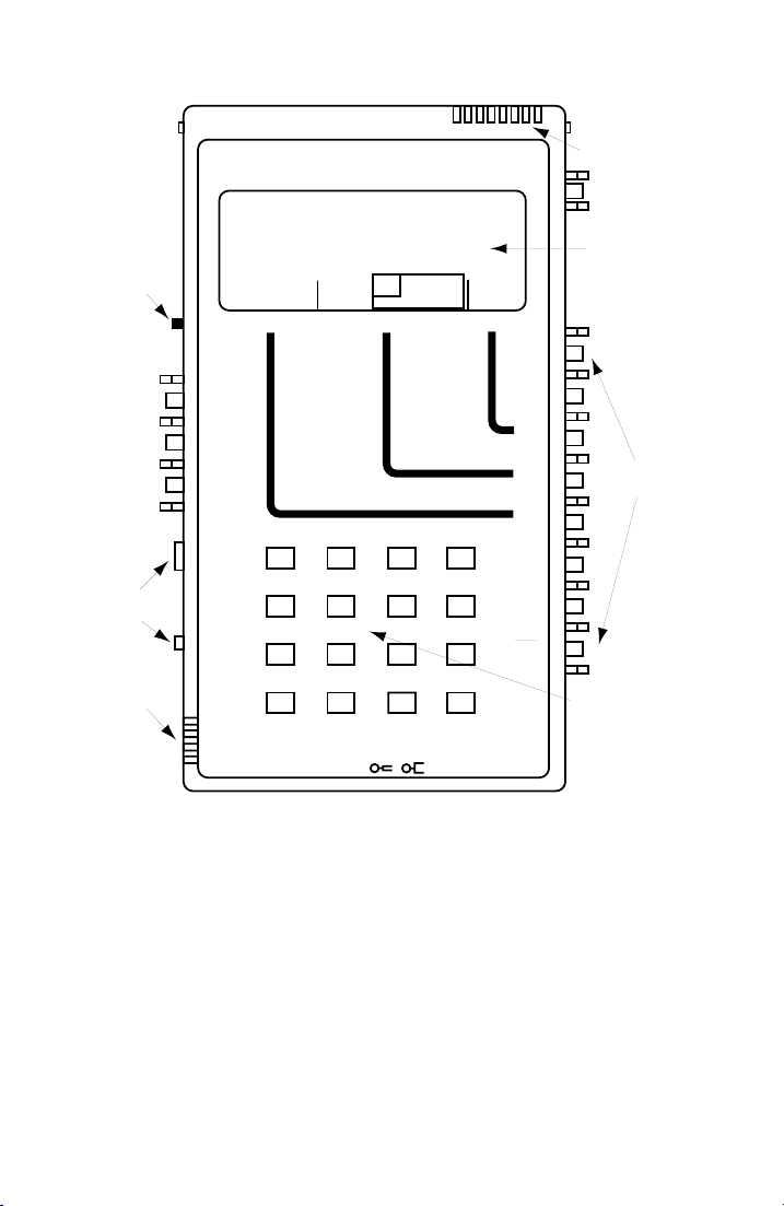
Figure 3-1 shows the location of components on the front panel and
sides.
Front Panel . Liquid crystal display and keyboard.
Sides . There are two (2) slide switches on the left side and a total of
12 color-coded rocker switches along the left and right sides. The
rocker switches are protected from abuse by integral "ribs" molded
into the case. A thumb wheel speaker volume control and slots for
the microphone are also located on the left side.
Top and Bottom . The slots at the top are for the speaker.
Connectors for the transmission line, AC adapter, earphone, and
printer are located along the bottom, as illustrated in Figure 3-2.
Rear Panel . You may access the battery compartment through a slide
door in the rear panel. See ¶4.2 and 4.3 for details.
0015-S033-2
Page 27
AM-48 Test Set (18-0015) Unit Description
3-3
Ameritec
SPEAKER
ON
∇
•
∇
ON/
OFF
MF
LIQUID
CRYSTAL
DISPLAY
∇
•
∇
∇
∇
∇
∇
∇
∇
∇
∇
∇
•
∇
∇
•
∇
∇
∇
ROCKER
SWITCHES
KEYBOARD
THUMB
WHEEL
SLIDE
SWITCHES
MICROPHONE
PERSONAL TRANSMISSION TEST SET
MODEL AM-48
QUIET 1004 VAR
VOL
∇
MON RCV
MON SND
•
∇
TALK
∇
TERM
∇
BRDG
∇
TONE
PULSE
•
∇
ON HK
∇
900Ω
600Ω
∇
∇
2W
4W
•
4W REV
∇
MIC
PRT EARDC9V
PAR
SEND MEASURE FILTER
*
∇
HOLD
L/F
NOISE NOISE S/N
TONE
PAR3 TONE SWEEP
∆
IMPLS ØJTR JTR TRANS
∇
21 A3
54 B6
87 C9
0
STOPSTART
∇
4W/2W
SND4WRCV
ETR/NEXT
ETR/PREV
CANCEL
D#
+/-
3K C-MSG
15K PROG
RCL/STO
ABS
REL
SEND
DAMP
OFF
DTMF
SHIFT
SF SKP
NOR
X TONE
PRINT
SEL
SEL
SEL
CONNECTORS (On Unit End) (Shown in Figure 3-2)
Figure 3-1. AM-48 Location of Components
3.4 Connectors and Cables
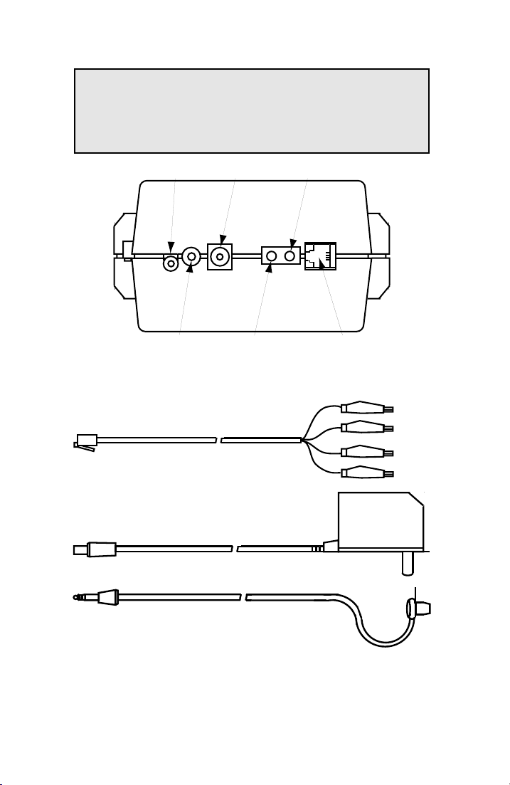
AM-48 connectors are shown in Figure 3-2. Figures 3-3 and 3-4
illustrate the standard and optional cables available for use with the
AM-48. See ¶6.3 for cable connection instructions.
0015-S03
Page 28
Unit Description (18-0015) AM-48 Test Set
Note: The AM-47 Hand-held Printer includes its own cable, P/N
48-0079. The Printer Cable P/N 48-0078 is for connection
to the RS-232 port (25-pin female) of most other serial EIA
printers..
PRINTER JACK
<PRT>
AC ADAPTER
PLUG <DC 9V>
4-WIRE RECEIVE
BANTAM JACK
RJ-11
2.5 mm JACK
EARPHONE JACK
<EAR>
4-WIRE SEND,
2-WIRE
BANTAM JACK
Figure 3-2. AM-48 Connectors
CABLE 48-0049, 7 Ft
AC ADAPTER 70-0029, 6 Ft
EARPHONE 82-0005, 3 Ft
Figure 3-3. Standard AM-48 Cables
RJ11 MODULAR
JACK
YELLOW
GREEN
RED
BLACK
0015-S033-4
Page 29
AM-48 Test Set (18-0015) Unit Description
3-5
GREEN
BANTAM PLUG
CABLE 48-0062, 6 Ft
RED
BLACK
R
T
S
BANTAM PLUG BANTAM PLUG
BANTAM PLUG
CABLE 48-0047, 6 Ft
CABLE 48-0048, 6 Ft
310 PLUG
2.5 mm JACK
PRINTER CABLE 48-0079, 6 Ft
4-WIDE
MODULAR
2.5 mm PLUG
2.5 mm PLUG
PRINTER CABLE 48-0078, 6 Ft
DB25 PLUG
Figure 3-4. Optional AM-48 Cables
3.5 Switches
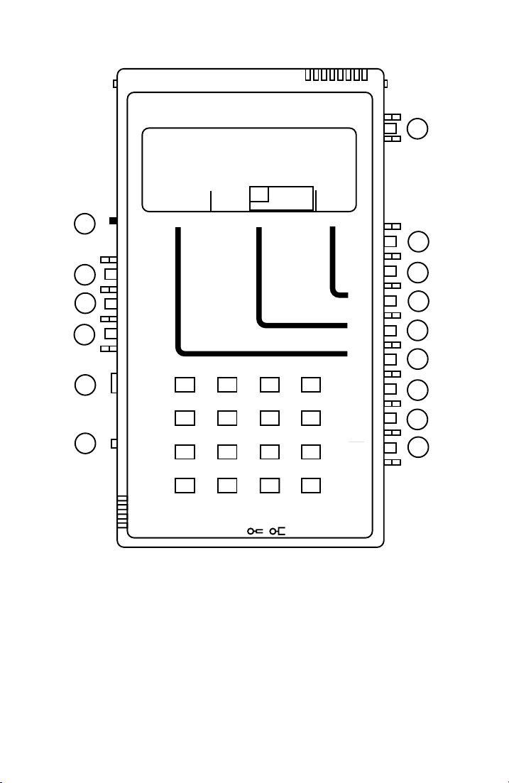
Figure 3-5 shows the location of the AM-48 switches. The functional
descriptions of the switches in this paragraph follows the same
numbering scheme as Figure 3-5.
Note: Throughout this manual, a switch position indicated on the
front panel is referred to with angular brackets, <>. For
example, <ABS> refers to the absolute measurement position
of Switch 2.
Switches are referred to by number throughout this manual.
See Figure 3-5 for ease of reference of switch numbers.
0015-S03
Page 30
Unit Description (18-0015) AM-48 Test Set
Ameritec
PERSONAL TRANSMISSION TEST SET
MODEL AM-48
ON
ON/
OFF
∇
•
∇
1
15
14
13
12
11
10
QUIET 1004 VAR
VOL
∇
MON RCV
MON SND
•
∇
TALK
∇
TERM
∇
BRDG
∇
TONE
PULSE
•
∇
ON HK
∇
900Ω
600Ω
∇
PAR
SEND MEASURE FILTER
HOLD
L/F
NOISE NOISE S/N
TONE
PAR3 TONE SWEEP
IMPLS ØJTR JTR TRANS
21 A3
54 B6
∇
2W
4W
•
4W REV
∇
MIC
PRT EARDC9V
*
87 C9
0
4W/2W
SND4WRCV
STOPSTART
∇
∇
∆
∇
ETR/NEXT
ETR/PREV
CANCEL
D#
+/-
3K C-MSG
15K PROG
RCL/STO
ABS
REL
SEND
DAMP
OFF
SEL
SEL
SEL
DTMF
SHIFT
SF SKP
NOR
X TONE
PRINT
MF
Figure 3-5. AM-48 Switch Identification Numbers
∇
•
∇
∇
∇
∇
∇
∇
∇
∇
∇
∇
•
∇
∇
•
∇
∇
∇
2
3
4
5
6
7
8
9
0015-S033-6
Page 31

AM-48 Test Set (18-0015) Unit Description
3
There are three (3) types of switches:
Thumb Wheel : "Switch" 15 is the only thumb wheel. It is a
volume control. Push up (toward the front panel) on <VOL> to
increase the volume of the monitor speaker. Push down on
<VOL> to decrease the monitor speaker volume.
Slide Switches : Switches 10 and 11 are slide switches. Push
these switches toward the top or the bottom in the direction
indicated by the arrows on the front panel to select the desired
line parameter.
Rocker Switches : The other 12 switches are rocker switches.
The action of these switches is rather like a rocking chair. Rock
the appropriate switch toward or away from the front panel as
indicated by the arrows to activate the desired function. There
are various combinations between toggle and/or momentary
switching action as explained in the functional descriptions
which follow (reference Figure 3-5).
1
Power . Combination toggle and momentary rocker switch.
• Set to <ON> position for power to be on continuously.
• To allow the AM-48 to power down by itself, turn the
power on by momentarily pressing the switch toward
the <ON/OFF> position. The power will shut off
automatically after the TIME OFF setting, if the unit is
left unattended. (See ¶7.12 for instructions to set the
time).
• To turn the power off, momentarily press the switch
toward the <ON/OFF> position.
0015-S03
-7
Page 32

Unit Description (18-0015) AM-48 Test Set
2
Display Select . Three-position toggle switch. This
determines what is being viewed on the display.
• Set <ABS> to view MEASUREMENT mode in
reference.
• Set <REL> to view MEASUREMENT mode in
reference.
• Set <SEND> to view the SEND mode.
See ¶7.22 and 8.2 for explanation of absolute and relative
measurements.
3
Two-position toggle switch. This switch has a dual
function:
A. Controls the display damping. <DAMP> gives a
display update of two times per second (used with
widely fluctuating signals to update the display more
often for better sampling of the measurement).
<OFF> gives a display update of four times per
second.
absolute
relative
B. Controls the monitoring point of the receive monitor
speaker (<MON RCV> position of Switch 14).
<DAMP> gives a monitoring point at the output of the
auto-range amplifier, significantly increasing the
spaeker level.. See Figure 9-1 for a block diagram
showing how this switch interacts with Switch 14.
0015-S033-8
Page 33

AM-48 Test Set (18-0015) Unit Description
3-9
4
Filter Select . Dual momentary switch. Rock up or down
to move FILTER menu cursor left or right to select desired
noise-weighting filter. See Table 7-5 for a list of
measurements that require a noise-weighting filter. See
Figure 3-8 for the FILTER menu.
5
Measure Select . Dual momentary switch. Rock up or
down to move MEASURE menu cursor left or right to
select desired measure mode. See Figure 3-8 for the
MEASURE menu.
6
Send Select . Dual momentary switch. Rock up or down
to move SEND menu cursor left or right to select desired
send (generator) mode. See Figure 3-8 for the SEND
menu.
7
Three-position toggle switch. See Table 7-6 for
interaction of this switch with Switch 12 for dialing.
• Set <MF> to dial multi-frequency tones from the
keyboard.
• Set <DTMF> to dial DTMF (Touch Tone) from the
keyboard.
• Set <SHIFT> to enable the auxiliary functions on the
keyboard. See ¶3.6 for details.
0015-S03
Page 34

Unit Description (18-0015) AM-48 Test Set
8
Two-position toggle plus momentary switch.
• Set <SF SKP> to skip the signaling frequency band of
2450 Hz to 2750 Hz (2130 Hz to 2430 Hz for
AM-48E), avoiding the accidental transmission of
signaling frequencies.
• Set <NOR> to allow the internal signal generator to be
stepped through all frequencies within its range while
in the SWEEP and VAR
• Press <X TONE> to momentarily send a 2713 Hz tone,
overriding the internal signal generator. This feature
is useful for actuating loopback devices. See ¶6.6
Loopback Testing " for the procedure to use the
under "
Western Electric Model 829 loopback device.
9
Dual momentary switch.
• Press <RCL/STO> to recall and/or store up to 10 test
setups. See ¶7.36 for details.
• Press <PRINT> to send unit setup and measurement
results to the printer port, <PRT>. See ¶3.9 and 7.39
for details.
SEND modes.
10
Three-position slide switch. See Figure 6-1 and 6-2 for
2-wire and 4-wire line connections associted with this
switch.
• Set <2W> to connect the internal measurement
circuitry and signal generator across the 2-wire line at
the <SND> jack. The signal generator source
impedance of 600 or 900 ohms terminates the line in
all signal generator modes except QUIET.
0015-S033-10
Page 35

AM-48 Test Set (18-0015) Unit Description
3
In QUIET mode, the line will be terminated only if
Switch 13 is set to <TERM>. See Figure 6-1.
Note: The <RCV> jack is not used when connecting
to 2-wire circuits.
• Set <4W> to connect the internal measurement
circuitry to the <RCV> pair, and the internal signal
generator to the <SND> pair. See the upper half of
Figure 6-2.
• Set <4W REV> to reverse the send and receive pairs.
See the lower half of Figure 6-2.
11
Two-position slide switch.
• Set <600 Ω> (usual position for 4-wire) to
A. apply 600 ohms across the receive pair when
Switch 13 is set to <TERM> and,
B. set the send pair source impedance at 600 ohms.
• Set <900 Ω> (usual position for 2-wire) to
A. apply 900 ohms across the receive pair when
Switch 13 is set to <TERM> and,
B. set the send pair source impedance at 900 ohms.
12
Three-position toggle switch. See Table 7-6 for
interaction of this switch with Switch 7 for dialing.
• Set <TONE> to come off-hook to dial either MF or
DTMF (set Switch 7 to <MF> or <DTMF>
accordingly). <TONE> causes a 200 ohm DC short
across T& R of the send pair to simulate a telephone
off-hook condition on 2-wire dial access lines.
0015-S03
-11
Page 36

Unit Description (18-0015) AM-48 Test Set
Press a button on the 16-button keypad to generate the
appropriate DTMF or MF tone pair, depending on the
setting of Switch 7. See Table 7-7 for a list of MF and
DTMF tone pairs generated by pressing the keys.
• Set <PULSE> to dial pulse. Switch 7 must be set at
either <MF> or <DTMF>. <PULSE> causes a 200 ohm
DC short across T & R of the send pair to simulate a
telephone
off-hook condition on 2-wire dial access
lines. Press a button on the 16-button keypad while in
this mode to cause the DC short to make and break at
10 PPS, 60% break, creating dial pulses in accordance
with the button pressed.
• Set <ON HK> to
pair to simulate a telephone
open the DC across T & R of the send
on-hook condition on
2-wire dial access lines. The 16-button keypad stays
operational, and if pressed, will send out DTMF or
MF tones (see Table 7-7) as selected by Switch 7.
13
Two-position toggle switch.
• Set <TERM> to terminate the
receive (<RCV>) line
with a resistive impedance as elected by Switch 11.
• Set <BRDG> unterminate the receive line and bridge it
only with the impedance of the measurement circuitry
(>25 kohms) across the receive pair.
0015-S033-12
Page 37
AM-48 Test Set (18-0015) Unit Description
3-13
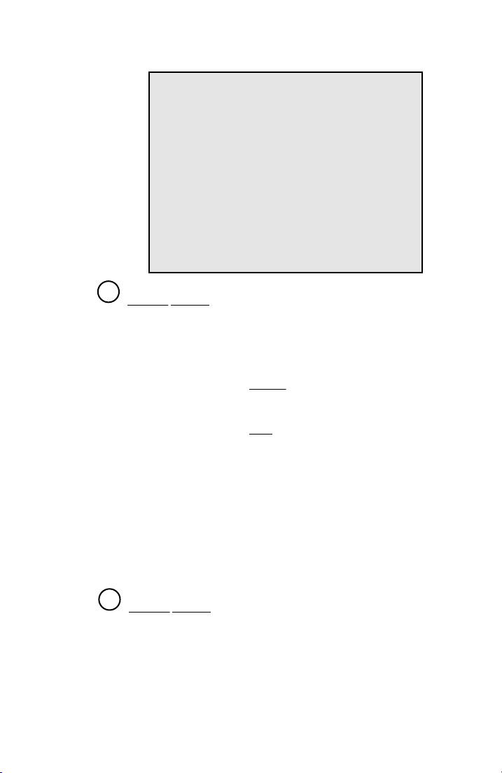
Note: In 2-wire mode, the signal generator source
impedance will terminate the line with 600 or
900 ohms, regardless of the position of
<TERM> / <BRDG>. If the "QUIET" send
mode is selected while in 2-wire bridge mode,
the signal generator will be disconnected from
the send pair, and the send pair source
impedance will be >25 kohms. This will
allow the <TERM> / <BRDG> switch to
function.
14
Speaker Control . Two-position toggle and momentary
switch. See Figure 9-1 for a block diagram showing how
this switch interacts with Switch 3.
• Set <MON RCV> to connect the internal speaker to
audibly monitor the
• Set <MON SND> to connect the internal speaker to
audibly monitor the
receive pair.
send pair.
0015-S03
• Push <TALK> to mute the speaker and connect the
internal microphone to allow "talking" over the send pair.
This feature is useful in voice communication with an
assistant technician at the distant end of the transmission
line being tested. It also allows the AM-48 to be used as a
conventional push-to-talk telephone set on 2-wire dial
networks. See ¶7.38 for more details.
15
Volume Control . This controls the gain of the internal
speaker amplifier. Use this to set the speaker or earphone
loudness to a comfortable level.
Page 38
Unit Description (18-0015) AM-48 Test Set
Note: Switch 3 and Switch 14 control the speaker/
earphone monitoring point. See Figure 9-1 for a
block diagram showing the interaction of these
switches. When Switch 3 is set to <DAMP>, the
monitor point is after the auto-range amplifier,
which significantly increases the speaker level.
WARNING
For a given volume setting, the earphone audio level
sounds much higher than the speaker level. Be careful
to adjust the audio volume down before inserting the
earphone into the ear.
3.6 Keyboard
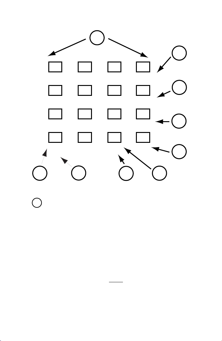
See Figure 3-6 for the AM-48 keyboard with identification numbers
which are referenced in the descriptions of this paragraph.
Auxiliary Functions . The AM-48 is equipped with auxiliary keypad
functions which are identified in Figure 3-6 with reference numbers 2
thru 9. The keys and their auxiliary functions are:
[*] START
[#] STOP
[A] ETR/NEXT
[B] ETR/PREV
[C] CANCEL
[D] ±
Note: To enable the auxiliary functions, set Switch 7 to <SHIFT>.
0015-S033-14
Page 39
AM-48 Test Set (18-0015) Unit Description
3-15
1
2
21 A3
ETR/NEXT
54 B6
ETR/PREV
87 C9
CANCEL
0
*
∇
9
Figure 3-6. AM-48 Keyboard Identification Numbers
1
16-Key Array. The function of the keys depends on the
positions of Switch 7 and Switch 12 (Figure 3-5). See Table
7-1.
To use the keys to dial MF, DTMF, or pulse, set Switches 7
and 12 as shown in Table 7-6. See Table 7-7 for a list of the
dual tones for the different keys.
With Switch 7 in <SHIFT>, the number keys can enter new
parameter values (¶7.8), or momentarily send user-
programmed tones from the QUIET SEND display (¶7.13). The
auxiliary functions of the other keys are described next.
8
STOPSTART
∇
7
D#
+/-
6
3
4
5
0015-S03
Page 40

Unit Description (18-0015) AM-48 Test Set
2
3
[ETR/NEXT], [ETR/PREV]. These keys have a dual
function:
A. To enter new parameter values into memory.
B. To scroll through multiple displays.
After using the number keys to input a new parameter value:
1) Press either [ETR/NEXT] or [ETR/PREV] to enter the
new value into memory.
2) Then press [ETR/NEXT] to step to the next display, or
press [ETR/PREV] to step to the previous display.
If no change was made to the display, or a change was made
with the [∆] or [∇] keys, press [ETR/NEXT or [ETR/PREV] once
to go immediately to the next/previous display. See ¶7.8 for
complete details.
4
[CANCEL]. Press [CANCEL] to erase a value input with the
number keys. The display defaults to the previous value. To
erase an input, press [CANCEL] before pressing [ETR/NEXT] or
[ETR/PREV]. [CANCEL] does not operate after pressing [∆] or
[∇] to change a value. See ¶7.8 for complete details.
5
[±]. This key is used to designate a positive or negative
polarity for a new parameter value input with the number keys.
See ¶7.8 for complete details.
0015-S033-16
Page 41

AM-48 Test Set (18-0015) Unit Description
3
6
9
[START], [STOP]. These keys are used in the IMPLS
(impulse noise) and TRANS (transients, i.e., impulse noise,
phase hits, gain hits, and dropouts) modes to stop/start the
timed test. See ¶7.24 for information on timed tests. The
[START][STOP] functions are in operation only when data is
displayed, i.e., not when a user-entered parameter is displayed.
With a user-entered parameter displayed, these same keys take
on the functions explained for number 7 and 8.
8
7
[∆∆∆∆] / [∇]. Press [∆] or [∇] to step the value of any variable
number displayed either up or down. Hold down [∆] or [∇] for
one (1) second to enable auto-repeat mode and step in
increments ten (10) times the normal increments. See Table
7-2 for the values of the increments, depending on the
parameter.
3.7 Display
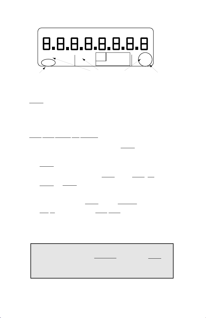
Figure 3-7 shows the AM-48 liquid crystal display:
1. The top line in Figure 3-7 shows all the possible units of
measurement. The units of measurement appear as appropriate
to label the value(s) displayed in the main display field. Time
and Count parameters do not show the units on the display.
2. The main display field has nine (9) 7-segmented characters with
decimal points. The prompts that appear on the display are
"pseudo-alpha" because of the limitations of the 7-segmented
characters. There are three (3) possible types of display fields,
as explained in ¶7.4.
3. Below the main display field are the menus for the three (3)
cursors, shown in detail in Table 3-2.
0015-S03
-17
Page 42
Unit Description (18-0015) AM-48 Test Set
UNITS OF
MEASUREMENT
9-CHARACTER
DISPLAY FIELD
MENUS
FOR AM-48E
PSHO
SWTD
AM-48E
SLOPE
QUIET
DBRN
DBM DB REL
1004 VAR
L/F
PAR
PAR3 TONE SWEEP
DEFAULT CURSOR POSITIONS WHEN POWER TURNED ON
HOLD
NOISE NOISE S/N
TONE
IMPLS ØJTR JTR TRANS
∆
∇
HZ PAR
3K C-MSG
15K PROG
Figure 3-7. AM-48 Liquid Crystal Display
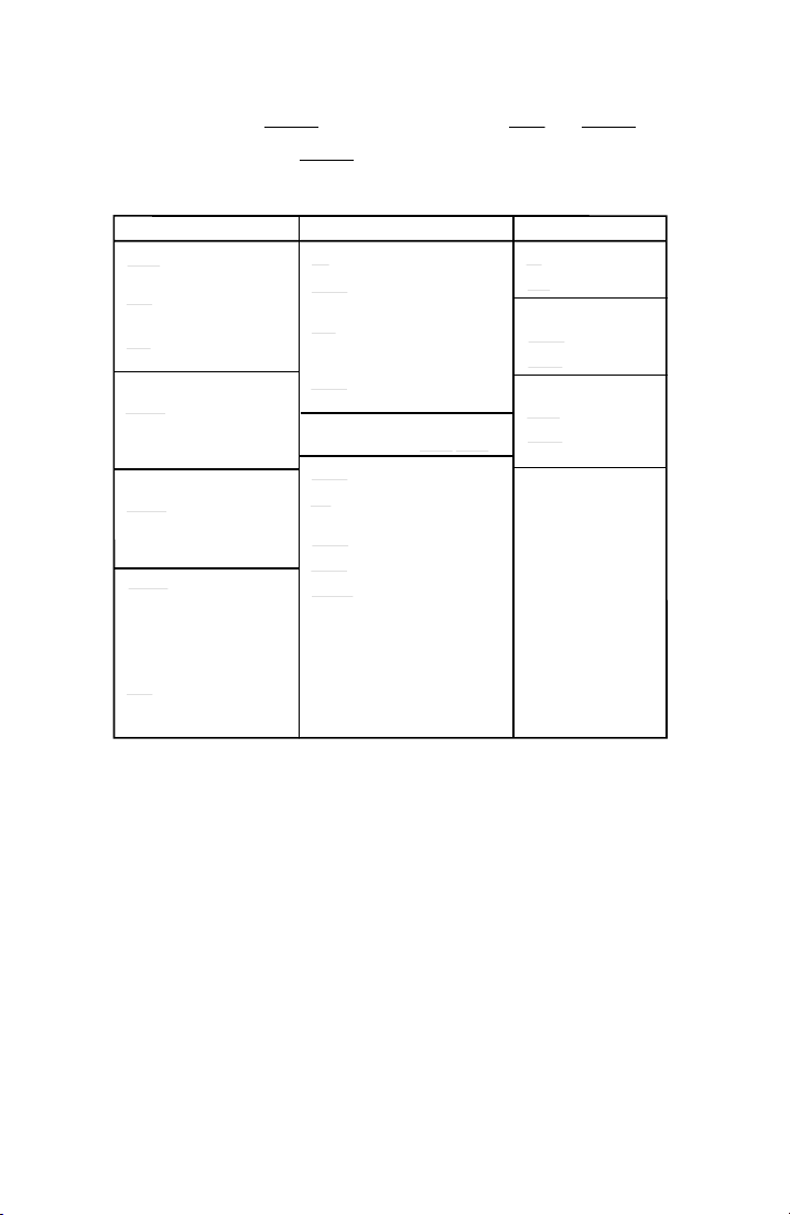
Menus . Table 3-2 defines each possible cursor position for the three
(3) menus. The positions of the three (3) cursors identify the present
SEND mode, MEASURE mode, and FILTER selected. Switches 4, 5,
and 6 move the cursors to select the desired mode of operation.
Menu Color Coding and Framing .
1. All send modes on the SEND menu are yellow .
2. All noise-weighting filter options on the FILTER menu are
orange .
3. On the MEASURE menu, both NOISE modes, IMPLS, S/N, and
TRANS are orange , indicating that these measurements require a
noise-weighting filter.
4. All MEASURE modes
holding tone. The HOLD TONE indicator in the corner of
1004 Hz
within the pink rectangle require a nominal
the rectangle darkens when a valid holding tone is present at the
receive port.
See Table 7-5 for a summary of measurement requirements.
Note: Throughout this manual cursor positions are referred to with
ALL CAPITAL LETTERS, underlined . For example, QUIET
always refers to the Quiet SEND menu cursor position and
associated Quiet mode.
0015-S033-18
Page 43
AM-48 Test Set (18-0015) Unit Description
3-19
The SEND menu is yellow , the MEASURE menu is pink and orange ,
and the FILTER menu is
orange .
Table 3-2. AM-48 SEND, MEASURE, and FILTER Menus
MEASURE MODES
Level/Frequency
L/F
Idle Channel
NOISE
Noise
PAR
Peak-to-Average
Ratio with
Receive Level
IMPLS
Impulse Noise
(Timed Test)
MEASURE MODES LISTED BELOW
NEED 1004 HZ HOLD TONE
Notched Noise
NOISE
S/N
Signal-to-Noise
Ratio
Phase Jitter
∅ JTR
∆
JTR Amplitude Jitter
∇
TRANS
Transients
(Timed Tests):
Impulse Noise,
Phase Hits,
Gain Hits,
Dropouts
FILTER OPTIONS
3K
15K
AM-48 ONLY:
C-MSG
PROG
AM-48E ONLY:
PSHO
SWTD
3 kHZ
15 kHZ
C-Message
Program
Psophometric
SoundWeighted
QUIET
1004
VAR
3TONE
SLOPE
SWEEP
PAR
SEND MODES
Passive Resistor
Termination
1004 Hz Tone
@ Selelcted Level
Variable Continuous
Frequency & Level
AM-48 ONLY:
404 Hz, 1004 Hz,
2804 Hz for 5 sec.
Cyclic @ Selected
Level
AM-48E ONLY:
404 Hz, 1004 Hz,
2004 Hz, 3004 Hz
for 5 sec. Cyclic
@ Selected Level
Tones Stepped
per Selected
Level, Start/Stop
Frequencies,
Step Size and
Sweep Rate
Peak-to-Average
Ratio Waveform
@ Selected Level
3.8 Microphone/Speaker
The speaker is for "listening" on the send or receive pairs, and the
microphone is for "talking" on the send pair. See ¶7.38.
Pressing Switch 14 to <TALK> (momentary position) activates the
microphone.
0015-S03
Page 44

Unit Description (18-0015) AM-48 Test Set
Switches 3 and 14 control the speaker/earphone monitoring point.
See Figure 9-1 for a block diagram showing the interaction of these
switches. When Switch 3 is set to <DAMP>, the monitor point is
after the auto-range amplifier which significantly increases the
speaker level. This is particularly useful for audibly monitoring the
residual noise in notched noise and S/N Ratio measurements.
3.9 Hand-Held Printer
The AM-47 Hand-Held Printer is designed to be used exclusively
with the AM-48 to produce a hard copy of measurements and setups.
Table 3-3 lists technical specifications, Figures 3-8 and 3-9 provide
component locations, Figure 6-3 shows the connectors, and ¶7.39
contains the operating instructions.
Connectors . The connectors are used with the AC Adapter (70-0029)
and the Printer Cable (48-0079) as shown in Figure 6-3. The AC
Adapter is supplied with the AM-48, and the 48-0079 Printer Cable is
supplied with the AM-47 Hand-Held Printer. The input is a special
serial ASCII current loop compatible with the AM-48.
Power . Power is provided by an internal NiCad battery pack. When
the printer is connected, power to the AM-48 comes from the printer
battery pack, prolonging the life of the AM-48 batteries. There is an
internal recharging circuit in the printer that operates when the AC
Adapter is plugged in.
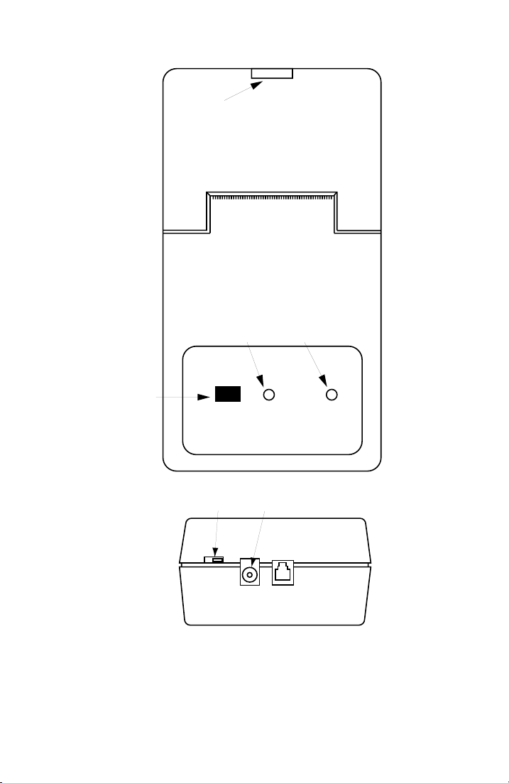
Power Switch . The slide switch to the left of the connectors is for
POWER ON/OFF.
LEDs . The LEDs light as described below:
1. The POWER LED lights continuously when the AC Adapter is
connected and the battery pack is charging (starts charge cycle
each time power is turned ON).
0015-S033-20
Page 45
AM-48 Test Set (18-0015) Unit Description
3
2. The POWER LED
blinks when power is ON and the battery pack
has been charged.
3. The SIGNAL LED lights when data is being received from the
AM-48.
Printing Mechanism . The printing mechanism is a dot matrix impact
type with a replaceable ribbon cartridge. It uses standard-width
adding machine paper. The ribbon cartridge and paper supply are
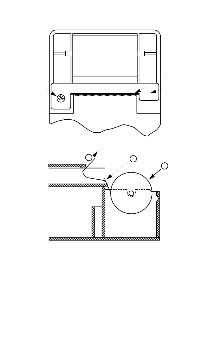
housed within the case (see Figure 3-9). The printout is in a
24-column format (see Figure 7-11 thru 7-13 for example printouts).
In order to conserve paper, no automatic space is made after a
printout. The paper can be advanced manually with the PAPER
ADVANCE button.
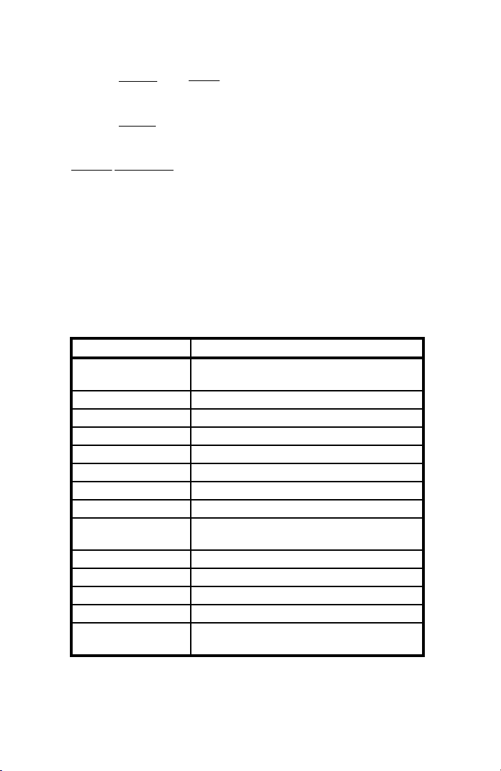
Table 3-3. AM-47 Hand-Held Printer Technical Specifications
CHARACTERISTICS SPECIFICATIONS
Input Signal Serial ASCII Code with 2-Wire Proprietary
Current Loop
Input Connector 4-Wide Modular Jack
Input Speed 300 Baud with 1500 Character FIFO Buffer
Print Type 6 x 8 Impact Dot Matrix
Paper 2.25”W x 1.8” Dia. Adding Machine Paper
Ink Supply Replaceable Inked Ribbon Cartridge
Characters per Line 24
Print Speed 0.7 Lines per Second
Power Internal NiCad Battery Pack with Built-In
Charger
Battery Life Approximately 10,000 Lines
Charge Time 8 to 14 Hours
Size 7.6”L x 3.4”W x 1.9”D
Weight 1.5 lbs.
Cables Printer Cable (48-0079), Supplied AC Adapter
(70-0029) (cables shown in Figures 3-3 & 3-4).
0015-S03
-21
Page 46
Unit Description (18-0015) AM-48 Test Set
PUSH UP HERE
TO REMOVE COVER
PAPER ROLL
COMPARTMENT
(See Figure 3-9)
PAPER CUTTER
BATTERY CHARGE/
PAPER FEED
BUTTON
POWER LED
Ameritec
HAND-HELD PRINTER • Model AM-47
PAPER
ADVANCE
POWER
OFF ON
DATA RECEIVE LED
POWER
9VDCINSIGNAL
IN
SIGNAL
TOP VIEW
POWER SWITCH
AC ADAPTER PLUG
END VIEW
Figure 3-8. Hand-Held Printer, External View
0015-S033-22
Page 47
AM-48 Test Set (18-0015) Unit Description
3-23
PAPER ROLL
RIBBON
MANUAL
RIBBON
TAKE-UP
RIBBON CARTRIDGE
PAPER CUTTER
PAPER ROLL COMPARTMENT
PUSH (PAPER ADVANCE)
BUTTON TO ROUTE
PAPER THROUGH
3
2
PAPER ROLL INSTALLATION
Figure 3-9. Hand-Held Printer, Internal View
FEED PAPER
INTO SLOT
PUSH DOWN
HERE TO
EJECT RIBBON
CARTRIDGE
INSTALL
PAPER
1
ROLL
0015-S03
Page 48
Unit Description (18-0015) AM-48 Test Set
3.10 Impedance Adapter
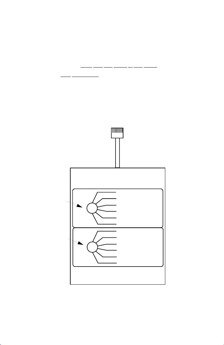
The Impedance Adapter (24-0005) is illustrated in Figure 3-10. It is
used to match the AM-48 to:
1. Line impedance
2. 4-Wire
split impedances
The Impedance Adapter has settings for five (5) different impedances
to match the AM-48 to the user interface. It plugs into the RJ11
modular connector of the AM-48. See ¶6.5 for installation, and ¶7.41
for measurement corrections when the Impedance Adapter is used.
The schematic of the Impedance Adapter is shown in Figure 9-2.
UPPER
KNOB
LOWER
KNOB
other than 600 Ohms or 900 Ohms
RJ11 PLUG
IMPEDANCE ADAPTER
MODEL 240005
THRU
1200 Ω
900 Ω
150 Ω
135 Ω
75 Ω
THRU
1200 Ω
900 Ω
150 Ω
135 Ω
75 Ω
SET AM4 SERIES TEST SET FOR 600 Ω
Ameritec
CORPORATION
Figure 3-10. Impedance Adapter
COVINA, CA. U S A
RJ11 JACK
4W/2W
SEND
4W
RCV
0015-S033-24
Page 49

AM-48 Test Set (18-0015) Power Considerations
4 POWER CONSIDERATIONS
4.1 General
This section covers AM-48 power considerations, including battery
installation, AC Adapter connection, and the power on/off switch.
The AM-48 runs on internal battery or external AC power. Flashing
display decimal points indicate low batteries; alkaline batteries need
replacing, and NiCad batteries need recharging.
Low-Level Noise Measurements . Power the AM-48 with batteries
when making a low-level noise measurement. Do
AM-48 with the AC Adapter for this test, because interference from
the AC source can affect the measurement.
4.2 Battery Compartment
The battery compartment under the rear panel is accessed through a
removable slide door. The compartment takes four (4) AA 1.5-volt
alkaline or NiCad batteries. The battery compartment also serves as a
recharger for NiCad batteries when the AM-48 is connected to 115
VAC with the AC Adapter.
not power the
4.3 Battery-Selector Switch
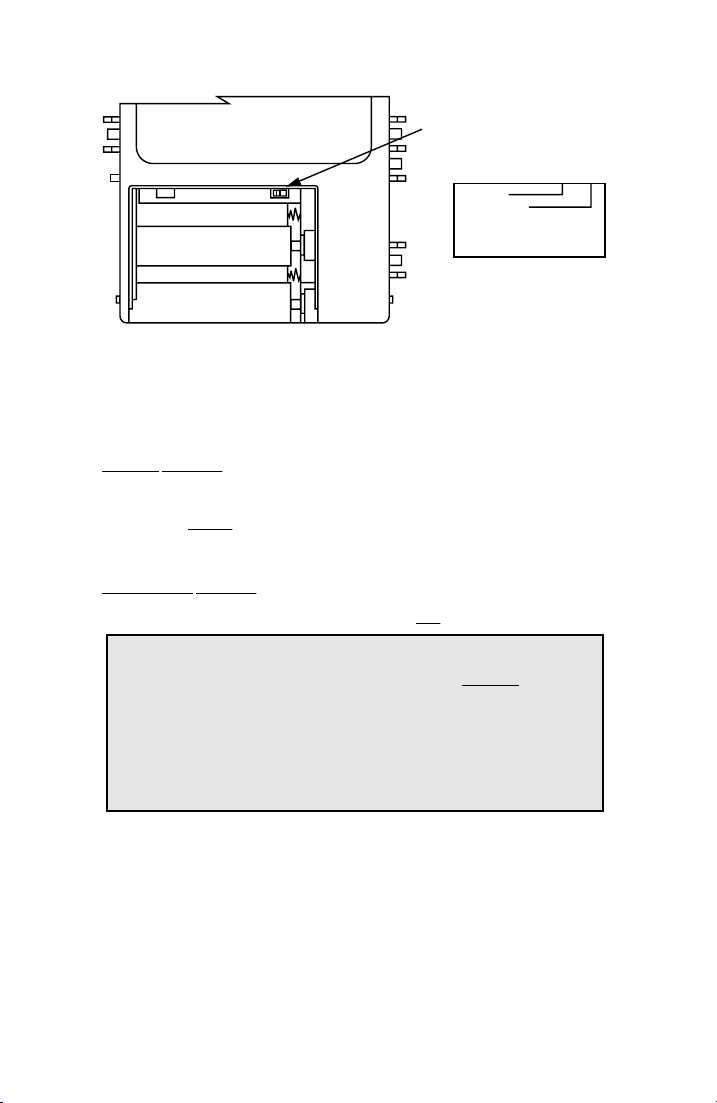
The Battery-Selector Switch is on the inside edge of the battery
compartment as shown in Figure 4-1.
0015-S04
4-1
Page 50
Power Considerations (18-0015) AM-48 Test Set
SELECTOR SWITCH
FOR BATTERY TYPE
NICAD
+
+
+
+
ALKALINE
CAUTION
SET SELECTOR SWITCH
FOR BATTERY TYPE USED
Figure 4-1. Battery Installation and Selector Switch
Using a pointed instrument, such as a pencil, set the Battery-Selector
Switch to “NICAD” or “ALKALINE” position to match the type of
battery used.
NICAD Position . This position connects the internal battery charge
circuitry to charge the NiCad batteries when the AC Adapter is
connected.
Never set the switch to this position when using alkaline
batteries.
ALKALINE Position . The internal battery charge circuitry is
disconnected because alkaline batteries are
not rechargeable.
WARNING: The Battery-Selector Switch MUST be in the
“ALKALINE” position when using alkaline batteries.
Alkaline batteries can explode if the AC Adapter is
used with alkaline batteries with the Battery-Selector
Switch in the “NICAD” position; warranty is voided if
this happens.
\ 0015-S044-2
Page 51

AM-48 Test Set (18-0015) Power Considerations
3
4.4 Battery Installation
To install the batteries:
1. Slide off the battery compartment cover.
2. Set the Battery-Selector Switch per ¶4.3.
3. Lay the ribbon in the base of the compartment (to be able to pull
up on the ribbon for easy removal of the batteries).
4. Install four (4) 1.5-volt AA NiCad or Alkaline batteries as
shown in Figure 4-1.
5. Replace the battery compartment cover.
4.5 Battery Information
General . When new, each battery will furnish approximately 1.5
Volts. The batteries are wired in series, supplying 6 VDC nominal.
An internal DC-to-DC Converter allows operation until the batteries
have discharged to approximately 3 Volts.
To avoid battery chemical leakage :
1. Use only first quality batteries
2. Do not subject the AM-48 to excessively high temperatures.
The warranty does
Alkaline Batteries . The AM-48 is shipped with four (4) high-quality
alkaline batteries, which give approximately 6-7 hours of service.
When the batteries have discharged to approximately 3.5 volts, the
display decimal points will flash. The flashing indicates
approximately 30 minutes of remaining operating life.
0015-S04
not cover damage resulting from battery leakage.
4-
Page 52

Power Considerations (18-0015) AM-48 Test Set
NiCad Batteries . Commercially available AA size Nickel Cadmium
(rechargeable) batteries can be used, but operating life will be
reduced to approximately 3 to 4 hours because of the limited energy
storage capacity of rechargeable batteries. Due to the abrupt end-of-
life discharge curve of Nickel Cadmium batteries, the flashing
decimal points low-battery indication will only provide a few minutes
of warning before the end of operation.
4.6 AC Power
To power the AM-48 with 115 VAC, plug one end of the AC Adapter
(70-0029) into the <DC 9V> connector on the bottom of the unit, and
the other end into an AC wall jack. See Figure 3-3 for the AC
Adapter, and Figure 3-2 for the AC Adapter plug on the AM-48.
The AC Adapter supplies 9 VDC to the AM-48. The locations of the
+ and – DC voltage contacts on the 2.5 mm jack of the AC Adapter
are illustrated on the transformer housing of the AC Adapter itself.
When using the AM-47 Hand-Held Printer, the AC Adapter can be
used to maintain the charge of the printer batteries that power the
AM-48. See Figure 6-3 for connections.
4.7 Power On/Off Switch
The Power On/Off Switch is a combination toggle switch and
momentary switch located at the top right-hand side of the AM-48
(Switch 1 in Figure 3-5).
Automatic Power Shutdown . To allow the AM-48 to power down by
itself, momentarily press the switch toward the <ON/OFF> position to
turn the power on. If the unit is left unattended, the power will shut
off automatically after the TIME OFF setting (see ¶7.12.4 for
instructions to set the time).
\ 0015-S044-4
Page 53

AM-48 Test Set (18-0015) Power Considerations
5
Continuous Power On . Set the switch to the <ON> position for power
to be on continuously.
Note: To turn power on continuously when battery voltage is less
than about 5 VDC, first turn power ON in momentary
<ON/OFF> position, then set switch to <ON>.
Power Off . To turn the power off, momentarily press the switch
toward the <ON/OFF> position.
The position of Switch 2 determines the initial display. The default
power-up cursor positions are shown in Figure 3-7.
0015-S04
4-
Page 54
AM-48 Test Set (18-0015) Self-Test Instructions
5
5 SELF-TEST INSTRUCTIONS
5.1 General
Purpose . This section has two (2) objectives:
1. To practice the main AM-48 operating procedures.
2. To verify that the AM-48 is working properly.
General . Each test in this section is described and illustrated. In the
figures, circled
description; circled
Note: Power is ON for the tests in this section. See Section 4
5.2 Self-Test Setup
Self-Test Setup is depicted in Figures 5-1 and 5-2.
Cable Connection . The tests in this section are done with the AM-48
looped back on itself, not connected to any external equipment. Plug
in the Modular-to-Minigator Cable (48-0049) (supplied with the
AM-48), and connect the minigator clips as shown in Figure 5-1.
The signals sent (generated) through the send port are routed directly
back to the receive port.
letters correspond to the steps of the written
numbers identify the switches.
concerning connecting and turning on power to the AM-48.
0015-S05
-1
Page 55
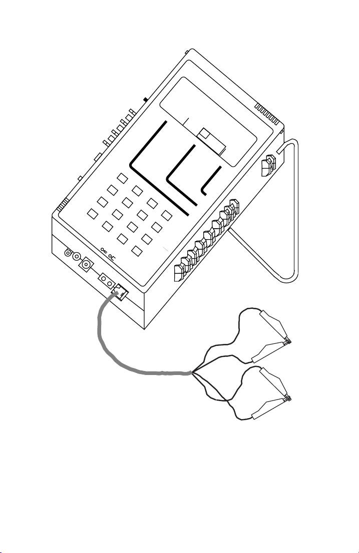
Self-Test Instructions (18-0015) AM-48 Test Set
Ameritec
PERSONAL TRANSMISSION TEST SET
QUIET 1004 VAR
VOL
MIC
PRT EAR
3 TONE SWEEP
SEND
PAR
A
X TONE
∇
SF SKP
NOR
∇
SHIFT
•
∇
DTMF
PAR
MF
•
∇
∇
L/F
NOISE
IMPLS ØJTR
TONE
MEASURE
SEL
∇
SEL
∇
∇
∇
MON RCV
•
∇
MON SND
TALK
∇
TERM
∇
BRDG
∇
TONE
•
∇
PULSE
ON HK
∇
∇
900Ω
600Ω
∇
2W
•
4W
∇
4W REV
START
*
∇
DC
9V
1
4
2
7
5
3
8
6
ETR/NEXT
4W/2W
SND
0
#
STOP
∇
4W
RCV
B
ETR/PREV
9
C
CANCEL
RCL/STO
PRINT
D
+
/
-
HOLD
∇
∇
∇
NOISE
∆
JTR TRANS
OFF
SEL
∇
FILTER
DAMP
∇
S/N
SEND
∇
15K
REL
∇
MODEL AM-48
3K
C-MSG
PROG
ABS
∇
•
∇
ON
∇
•
ON/
∇
OFF
Red (R)
Black (R1)
Yellow (T1)
Figure 5-1. AM-48 Setup for Self-Test (Looped Back)
Green (T)
0015-S055-2
Page 56
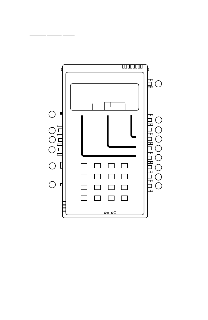
AM-48 Test Set (18-0015) Self-Test Instructions
5-3
General Switch Setup . Figure 5-2 shows the initial positions of the
switches for the tests in this section. Leave these switches in the
positions indicated unless otherwise directed in the instructions for
the individual tests. Switches are referenced by the circled numbers.
Ameritec
PERSONAL TRANSMISSION TEST SET
MODEL AM-48
ON
∇
•
1
∇
ON/
OFF
(MON SND)
(TERM)
(ON HK)
(600 Ω)
(4W)
15
14
12
13
11
10
QUIET 1004 VAR
VOL
∇
MON RCV
MON SND
•
∇
TALK
∇
TERM
∇
BRDG
∇
TONE
PULSE
•
∇
ON HK
∇
900Ω
∇
600Ω
PAR
SEND MEASURE FILTER
HOLD
L/F
NOISE NOISE S/N
TONE
PAR3 TONE SWEEP
IMPLS ØJTR JTR TRANS
21 A3
54 B6
∇
2W
4W
•
4W REV
∇
MIC
PRT EARDC9V
87 C9
0
*
∇
4W/2W
SND4WRCV
STOPSTART
3K C-MSG
∆
15K PROG
∇
∇
ABS
REL
•
SEND
∇
∇
DAMP
OFF
∇
∇
SEL
∇
∇
SEL
∇
∇
SEL
∇
∇
MF
DTMF
•
SHIFT
SF SKP
NOR
X TONE
RCL/STO
PRINT
∇
∇
•
∇
∇
∇
ETR/NEXT
ETR/PREV
CANCEL
D#
+/-
∇
3
4
5
7
8
2
6
9
(ABS)
(DAMP)
(SHIFT)
(NOR)
Figure 5-2. General Switch Setup for Self Test
Switches 4, 5, 6, and 9 do not have a set position because they are all
dual momentary switches. The instructions for each test will indicate
when to rock switches 5 and 6 to move the cursors to desired
positions on the display menus.
0015-S05
Page 57
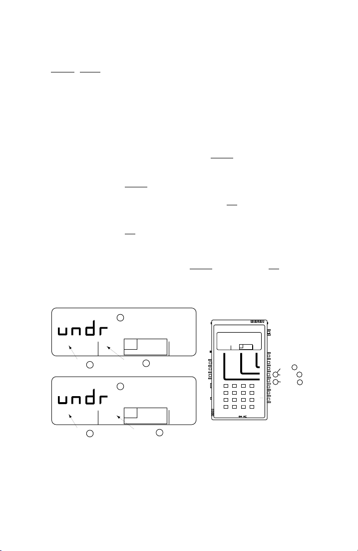
Self-Test Instructions (18-0015) AM-48 Test Set
The FILTER menu cursor (controlled by Switch 4) will default to
C-MSG (PSHO
for AM-48E) when power is turned on. Leave the
cursor in this position for all the tests in this section.
5.3 Quiet Send Mode
Quiet Send Mode switch settings and display are depicted in Figure
5-3.
A. Verify that the SEND menu cursor is in QUIET (default position
when power is first turned on). Rock Switch 6 if necessary to
move cursor to QUIET.
B. Verify that the MEASURE menu cursor is in L/F (default position
when power is first turned on). Rock Switch 5 if necessary to
move cursor to L/F (level/frequency).
C. Display should read “UNDR” with units “DBM” and “HZ”.
D. Rock Switch 5 to move cursor to NOISE (to the right of L/F
E. Display should read “UNDR” with units of “DBRN” (“DBM” for
AM-48E).
QUIET
QUIET
DBM
1004 VAR
QUIET
darkened
DBRN
1004 VAR
QUIET
darkened
L/F
NOISE NOISE S/N
IMPLS ØJTR JTR TRANS
PAR
PAR3 TONE SWEEP
A
L/F
NOISE NOISE S/N
PAR
PAR3 TONE SWEEP
IMPLS ØJTR JTR TRANS
A
C
L/F darkened
E
HOLD
TONE
∆
∇
HOLD
TONE
∆
∇
NOISE darkened
HZ
Ameritec
PERSONAL TRANSMISSION TEST SET
MODEL AM-48
3K C-MSG
15K PROG
B
3K C-MSG
15K PROG
QUIET 1004 VAR
L/F
NOISE NOISE S/N
PAR
PAR3 TONESWEEP
IMPLS ØJTR JTR TRANS
SEND MEASURE FILTER
VOL
∇
MON RCV
MON SND
•
∇
TALK
∇
TERM
∇
BRDG
∇
TONE
PULSE
•
∇
ON HK
∇
900Ω
21 A3
600Ω
∇
54 B6
∇
2W
4W
•
87 C9
4W REV
∇
0*D#
∇
MIC
4W/2W
PRT EARDC9V
SND4WRCV
HOLD
TONE
∆
∇
ETR/NEXT
ETR/PREV
CANCEL
STOPSTART
∇
D
Figure 5-3. Quiet Send Mode Self Test
).
ON
∇
•
∇
ON/
OFF
3K C-MSG
15K PROG
∇
ABS
REL
•
SEND
∇
∇
DAMP
OFF
∇
∇
SEL
Set L/F
∇
∇
SEL
∇
SEL
∇
MF
DTMF
•
SHIFT
∇
SF SKP
NOR
•
X TONE
∇
RCL/STO
∇
PRINT
+/-
B
∇
Set NOISE
5
∇
Set QUIET
6
∇
∇
D
A
0015-S055-4
Page 58
AM-48 Test Set (18-0015) Self-Test Instructions
5-5
5.4 Send 1004 Hz
Send 1004 Hz switch settings are depicted in Figure 5-4, while the
displays are depicted in Figure 5-5.
A. Rock Switch 6 to move SEND menu cursor to 1004.
Note: Turn volume control (“Switch” 15) up or down as desired to
increase or decrease the volume of the speaker sound. With
Switch 14 in <MON SND>, the speaker is monitoring the
1004 Hz tone being sent.
B. Rock Switch 5 if needed to move MEASURE menu cursor to L/F.
C. Read “00.0 ±0.1 DBM” and “1004 HZ” on display.
D. Rock Switch 5 to move MEASURE menu cursor to NOISE.
E. Read “90.0 ±1.0 DBRN” (“00.0 ±1.0 DBM” for AM-48E) on
display.
F. Rock Switch 5 to move MEASURE menu cursor to NOISE (to the
right of HOLD TONE ).
Note: HOLD TONE will be darkened for the remaining steps in this
paragraph.
G. Read typically “32.0 DBRN” (must be <40.0 dBrn) and “1004 HZ”
on display; for AM-48E, “-58.0 DBM” (must be <–50.0 dBm).
H. Rock Switch 5 to move MEASURE menu cursor to S/N (signal-to-
noise ratio).
I. Read typically “58.0 DB” (must be >50.0 dB) and “1004 HZ” on
display.
J. Rock Switch 5 to move MEASURE menu cursor to Ø JTR
K. Read “JITR 00.0 ±0.2˚” on display.
L. Rock Switch 5 to move MEASURE menu cursor to ∆ JTR
M. Read “JITR 00.0 ±0.2” on display.
0015-S05
.
.
Page 59
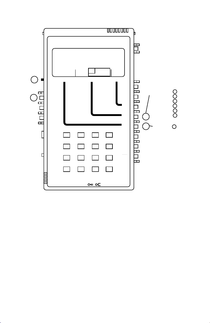
Self-Test Instructions (18-0015) AM-48 Test Set
Ameritec
PERSONAL TRANSMISSION TEST SET
MODEL AM-48
ON
∇
•
∇
ON/
OFF
14
15
QUIET 1004 VAR
PAR
SEND MEASURE FILTER
VOL
∇
MON RCV
MON SND
•
∇
TALK
∇
TERM
∇
BRDG
∇
TONE
PULSE
•
∇
ON HK
∇
900Ω
600Ω
∇
HOLD
L/F
NOISE NOISE S/N
TONE
PAR3 TONE SWEEP
IMPLS ØJTR JTR TRANS
21 A3
54 B6
∇
2W
4W
•
4W REV
∇
MIC
PRT EARDC9V
87 C9
0
*
∇
STOPSTART
4W/2W
SND4WRCV
3K C-MSG
∆
15K PROG
∇
∇
ABS
REL
•
SEND
∇
∇
DAMP
OFF
∇
∇
SEL
∇
∇
SEL
∇
5
∇
SEL
∇
6
∇
MF
DTMF
•
SHIFT
SF SKP
NOR
X TONE
RCL/STO
PRINT
∇
∇
•
∇
∇
∇
ETR/NEXT
ETR/PREV
CANCEL
D#
+/-
∇
Figure 5-4. Send 1004 Hz Self Test, Switch Settings
Set L/F
NOISE
NOISE
S/N
Set 1004
Ø
JTR
∆
JTR
∇
B
D
F
H
J
L
A
0015-S055-6
Page 60
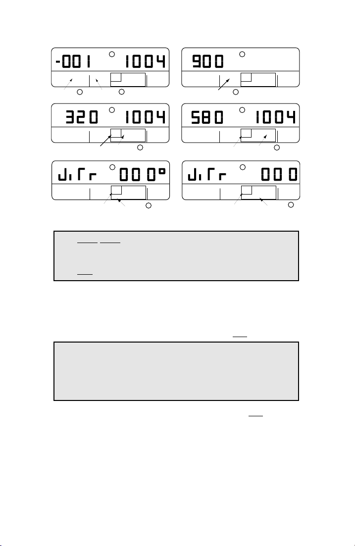
AM-48 Test Set (18-0015) Self-Test Instructions
5
DBM
•
QUIET
1004 VAR
L/F
NOISE NOISE S/N
PAR
PAR3 TONE SWEEP
1004 darkened L/F darkened
DBRN
IMPLS ØJTR JTR TRANS
A
•
QUIET
1004 VAR
L/F
NOISE NOISE S/N
PAR
PAR3 TONE SWEEP
IMPLS ØJTR JTR TRANS
See Note Below
QUIET 1004 VAR
L/F
NOISE NOISE S/N
PAR
PAR3 TONE SWEEP
IMPLS ØJTR JTR TRANS
See Note Below
C
HOLD
TONE
G
HOLD
TONE
K
HOLD
TONE
∆
∇
B
∆
∇
NOISE darkened
∆
∇
ØJTR darkened
HZ
3K C-MSG
15K PROG
HZ
3K C-MSG
15K PROG
F
•
3K C-MSG
15K PROG
J
DBRN
QUIET
1004 VAR
DB
QUIET
1004 VAR
QUIET 1004 VAR
•
L/F
NOISE NOISE S/N
PAR
PAR3 TONE SWEEP
IMPLS ØJTR JTR TRANS
NOISE darkened
•
L/F
NOISE NOISE S/N
PAR
PAR3 TONE SWEEP
IMPLS ØJTR JTR TRANS
See Note Below
L/F
NOISE NOISE S/N
PAR
PAR3 TONE SWEEP
IMPLS ØJTR JTR TRANS
See Note Below
E
HOLD
TONE
∆
∇
D
HZ
I
HOLD
TONE
∆
∇
S/N darkened
M
HOLD
TONE
∆
∇
∆
JTR darkened
∇
Figure 5-5. Send 1004 Hz Self Test, Displays
Note: HOLD TONE is darkened for all measurements with
MEASURE menu cursor inside the pink rectangle.
1004 is darkened for all tests in Figure 5-5.
5.5 Send PAR (Peak-to-Average Ratio)
Send PAR switch settings and display are depicted in Figure 5-6.
A. Rock Switch 6 to move SEND menu cursor to PAR.
Note: Turn volume control (“Switch” 15) up or down as desired to
increase or decrease the volume of the speaker sound. With
Switch 14 in <MON SND>, the speaker is monitoring the PAR
waveform being sent.
3K C-MSG
15K PROG
3K C-MSG
15K PROG
H
3K C-MSG
15K PROG
•
L
B. Rock Switch 5 to move MEASURE menu cursor to PAR.
C. Read “00.0 ±1.0 DBM 100 ±2 PAR” on display.
0015-S05
-7
Page 61
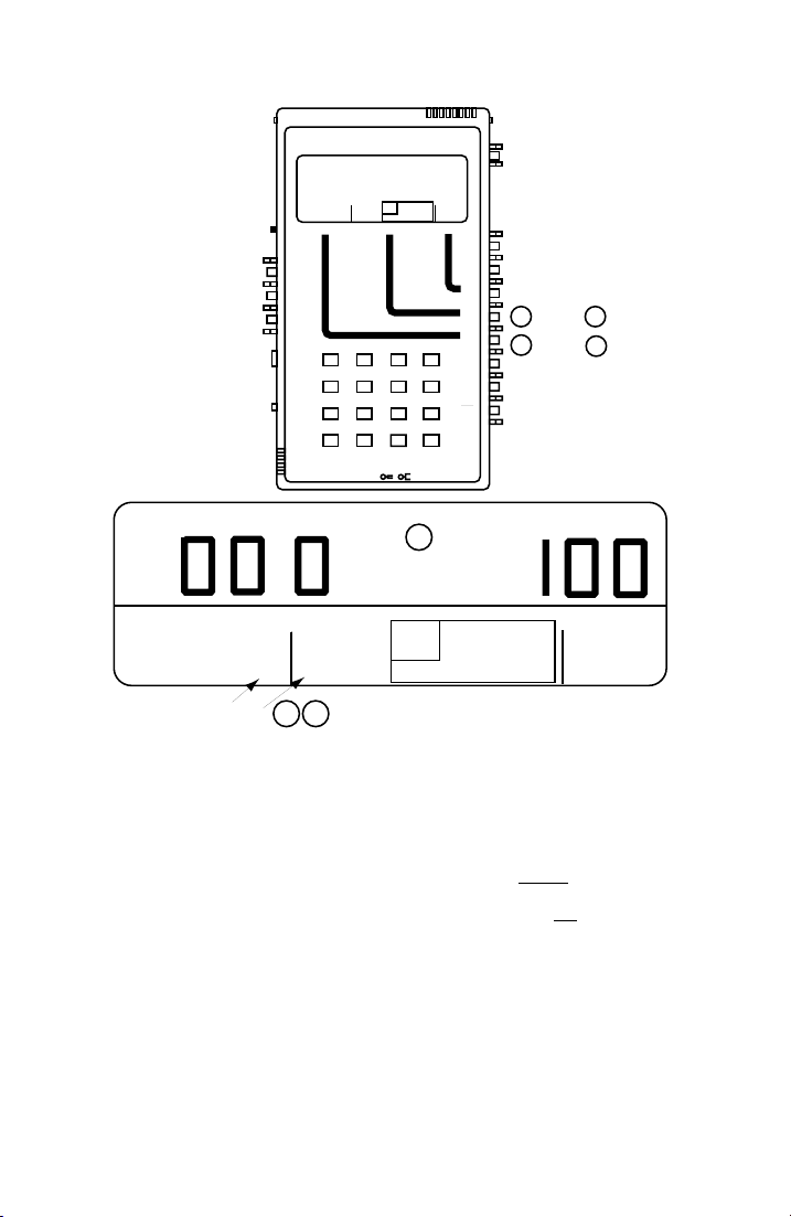
Self-Test Instructions (18-0015) AM-48 Test Set
Ameritec
PERSONAL TRANSMISSION TEST SET
QUIET 1004 VAR
VOL
SEND MEASURE FILTER
∇
MON RCV
MON SND
•
∇
TALK
∇
TERM
∇
BRDG
∇
TONE
PULSE
•
∇
ON HK
∇
900Ω
∇
600Ω
∇
2W
4W
•
4W REV
∇
*
∇
MIC
PRT EARDC9V
L/F
PAR
PAR3 TONE SWEEP
MODEL AM-48
HOLD
NOISE NOISE S/N
TONE
∆
IMPLS ØJTR JTR TRANS
∇
21 A3
54 B6
87 C9
0
STOPSTART
∇
4W/2W
SND4WRCV
ETR/NEXT
ETR/PREV
CANCEL
ON
∇
•
∇
ON/
OFF
3K C-MSG
15K PROG
∇
ABS
REL
•
SEND
∇
∇
DAMP
OFF
∇
∇
SEL
∇
∇
SEL
∇
Set PAR
5 B
∇
SEL
∇
Set PAR
6
∇
MF
DTMF
•
SHIFT
∇
∇
SF SKP
NOR
•
X TONE
∇
∇
RCL/STO
∇
PRINT
D#
+/-
A
DBM
C
PAR
•
QUIET
PAR darkened
1004 VAR
PAR
L/F
PAR3 TONE SWEEP
A B
HOLD
NOISE NOISE S/N
TONE
IMPLS ØJTR JTR TRANS
∆
∇
Figure 5-6. Send PAR (Peak-to-Average Ratio)
5.6 Dialing
Dialing switch settings and display are depicted in Figure 5-7.
A. Rock Switch 6 to move SEND menu cursor to QUIET.
B. Rock Switch 5 to move MEASURE menu cursor to L/F.
C. Set Switch 2 (display select) to <SEND>.
D. Set Switch 7 to <MF>.
E. Set Switch 12 to <TONE>.
3K C-MSG
15K PROG
0015-S055-8
Page 62

AM-48 Test Set (18-0015) Self-Test Instructions
5-9
F. Turn volume control (“Switch” 15) all the way up for maximum
speaker volume.
G. Press various keys on the keypad to dial MF (multiple
frequency) tones. Listen to the dual tones coming from the
speaker. The speaker will emit the tones as long as the key is
held down. Note that key [D] has no MF tones.
Note: See Table 7-7 for list of dual frequencies transmitted in tone
dialing.
H. When doing step G., the display will read “DIAL -10.0 DBM”.
This indicates that –10.0 dBm (factory setting) is the send level.
Tone dialing send level can be changed. See ¶7.12.3 and Figure
7-1 for “TTLEV” (Touch Tone Level) display.
I. Set Switch 7 to <DTMF>.
J. Press various keys on the keypad to dial DTMF (Dual Tone
Multiple Frequency) tones. Listen to the dual tones coming
from the speaker. The speaker will emit the tones as long as the
key is held down.
K. The display will read as in step H.
L. Set Switch 12 to <PULSE>.
M. Press the keys on the keypad and note that no sound is heard.
No battery is connected to the line and line battery voltage is
required for pulse dialing.
0015-S05
Page 63
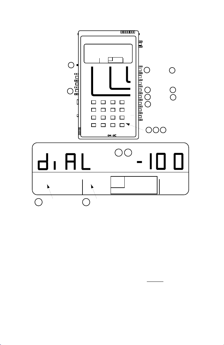
Self-Test Instructions (18-0015) AM-48 Test Set
Ameritec
PERSONAL TRANSMISSION TEST SET
QUIET 1004 VAR
VOL
15
12
SEND MEASURE FILTER
∇
MON RCV
MON SND
•
∇
TALK
∇
TERM
∇
BRDG
∇
TONE
PULSE
•
∇
ON HK
∇
900Ω
∇
600Ω
∇
2W
4W
•
4W REV
∇
*
MIC
PRT EARDC9V
PAR
∇
HOLD
L/F
NOISE NOISE S/N
TONE
PAR3 TONE SWEEP
IMPLS ØJTR JTR TRANS
21 A3
54 B6
87 C9
0
STOPSTART
4W/2W
SND4WRCV
MODEL AM-48
∆
∇
∇
ETR/NEXT
ETR/PREV
CANCEL
ON
∇
•
∇
ON/
OFF
3K C-MSG
15K PROG
∇
ABS
REL
•
SEND
2
(SEND)
∇
∇
DAMP
OFF
∇
∇
SEL
∇
∇
SEL
∇
5
∇
SEL
∇
6
∇
MF
DTMF
•
SHIFT
∇
7
∇
SF SKP
NOR
•
X TONE
∇
∇
RCL/STO
∇
PRINT
D#
+/-
G J M
Set L/F
Set QUIET
C
B
A
DBM
H K
•
QUIET
1004 VAR
PAR
QUIET darkened
A B
L/F
PAR3 TONE SWEEP
L/F darkened
HOLD
NOISE NOISE S/N
TONE
IMPLS ØJTR JTR TRANS
∆
∇
Figure 5-7. Dialing
5.7 Parameter Values for Send Sweep
Parameter Values for Send Sweep settings and display are depicted in
Figure 5-8.
A. Set Switch 2 to <SEND>.
B. Set Switch 7 to <SHIFT>.
C. Rock Switch 6 to move SEND menu cursor to SWEEP.
3K C-MSG
15K PROG
0015-S055-10
Page 64

AM-48 Test Set (18-0015) Self-Test Instructions
5
Note: The MEASURE menu cursor can be in any mode.
Turn volume control (“Switch” 15) up or down as desired to
increase or decrease the volume of the speaker sound. With
Switch 14 in <MON SND>, the speaker is monitoring the
frequencies being swept.
D. Display will read “00.0 DBM” and frequencies which start at “204
HZ” and increase in 100 Hz steps every second up to 19,904 Hz,
at which time the sweep starts again at 204 Hz.
E. Rock Switch 6 once to momentarily exit SWEEP mode. Rock
Switch 6 once in the opposite direction to re-enter SWEEP mode
(SEND menu cursor back to SWEEP). Note that the sweep starts
again at 204 Hz.
F. Press [ETR/NEXT] on the keypad ([A] key).
G. Display will change to “LEVL 00.0 DBM”. This is the first of
the five (5) default parameter settings shown in Figure 5-8.
H. Repeat Step F. four (4) more times and observe the NEXT
displays in sequence:
I. “STRT 204 HZ”
J. “STOP 19904 HZ”
K. “STEP 100 HZ”
L. “RATE 1.0”
M. Press [ETR/PREV] on the keypad ([B] key) five (5) times and
observe the PREVIOUS displays appear in reverse sequence.
Note: In the remaining steps, an example will be given of setting
new parameter values for the SWEEP mode. Carefully note
the procedure, because the same procedure is used for setting
all AM-48 parameter values.
0015-S05
-11
Page 65

Self-Test Instructions (18-0015) AM-48 Test Set
N. Repeat Step E. to start with the first SWEEP display.
O. Press [ETR/NEXT] to go to the NEXT display (sweep frequency
LEVEL).
P. Press [±], same as [D] key. Then press [5] and [0]. Display now
reads “LEVL -5.0 DBM”. Press [±] several times and notice the
“-“ sign appear and disappear. Leave display with the “-“.
Q. Press [ETR/NEXT] again. This enters the new LEVEL, -5.0 dBm.
R. Press [ETR/NEXT] to go to the NEXT display (START frequency
setting).
S. Press [4], [0], [0]. Display now reads “STRT 400 HZ”.
T. Press [ETR/NEXT] again. This enters the new START frequency,
400 Hz.
U. Press [ETR/NEXT] to go to the NEXT display (STOP frequency
setting).
V. Press [1], [6], [0], [0]. Display now reads “STOP 1600 HZ”.
W. Press [ETR/NEXT] again. This enters the new STOP frequency,
1600 Hz.
X. Press [ETR/NEXT] to go to the NEXT display (frequency STEP
setting).
Y. Display now reads “STEP 100 HZ”.
Note: In the next step, a “mistake” will be made when entering a
new parameter value to show how it can be corrected.
Z. Press [2], [0], [0]. Display now reads “STEP 200 HZ”. This is
a mistake; desired step is actually 300 Hz.
AA. Press [CANCEL], same as [C] key. The incorrect value is gone
and the display now reads as in Step Y.
BB. Press [3], [0], [0]. Display now reads “STEP 300 HZ”, the
desired value.
0015-S055-12
Page 66

AM-48 Test Set (18-0015) Self-Test Instructions
5-13
CC. Press [ETR/NEXT] again. This enters the new frequency STEP,
300 Hz.
DD. Press [ETR/NEXT] to go to the NEXT display (RATE, i.e. duration
of each frequency in the sweep).
EE. Display now reads “RATE 1.0”.
FF. Press [∆] momentarily repeatedly and notice the time
increase
0.1 sec at a time: 1.1, 1.2, 1.3. ….sec. Hold [∆] down
continuously and notice that the time starts increasing in steps of
1.0 sec; 2.0, 3.0, 4.0, ….sec. Press momentarily and/or hold
down [∇] and note that the time
decreases in steps of 0.1 and/or
1.0 sec. Use [∆] and [∇] as necessary to step the time (rate) to
2.0 sec.
GG. Display now reads “RATE 2.0”.
HH. Press [ETR/NEXT] to return to the original display. Instead of the
sweep that was seen in Step D., there is now a new sweep that
reflects the settings just entered. Display now reads “-05.0 DBM”
and shows frequencies which start at “400 HZ” and increase in
300 Hz steps every 2 seconds up to 1600 Hz, at which time the
sweep starts again at 400 Hz.
Note: The new parameter settings will remain until (1) they are
changed, or (2) power is turned off. If power is turned off,
the settings will revert back to the default settings as shown
in Figure 5-8.
This completes the self test. See Section 7 for complete operating
instructions and details of other tests and parameter settings not
covered here.
0015-S05
Page 67
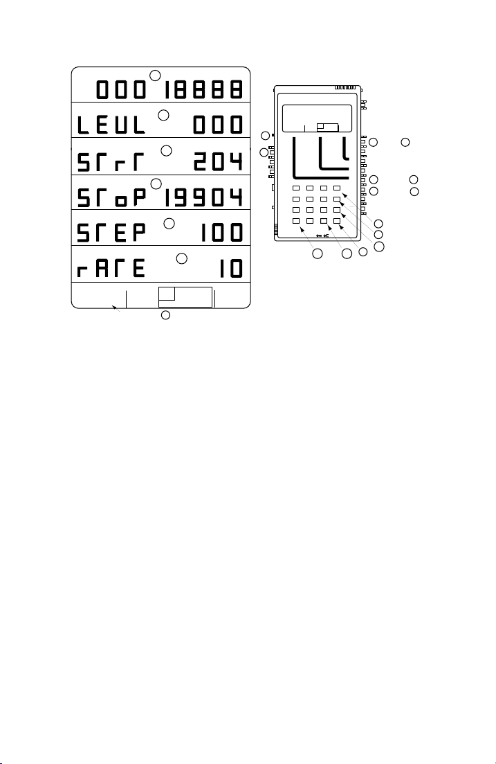
Self-Test Instructions (18-0015) AM-48 Test Set
DBM
DBM
D
•
G
J
HZ
Ameritec
PERSONAL TRANSMISSION TEST SET
•
HZ
I
HZ
HZ
K
VOL
15
∇
MON RCV
MON SND
•
∇
14
TALK
∇
TERM
∇
BRDG
∇
TONE
PULSE
•
∇
ON HK
∇
900Ω
600Ω
∇
∇
2W
4W
•
4W REV
∇
MIC
PRT EARDC9V
L
MODEL AM-48
HOLD
QUIET 1004 VAR
L/F
NOISE NOISE S/N
TONE
∆
PAR
PAR3 TONE SWEEP
IMPLS ØJTR JTR TRANS
∇
SEND MEASURE FILTER
21 A3
54 B6
87 C9
0*D#
STOPSTART
∇
∇
4W/2W
SND4WRCV
3K C-MSG
15K PROG
ETR/NEXT
SF SKP
X TONE
ETR/PREV
RCL/STO
PRINT
CANCEL
+/-
FFFF
•
QUIET 1004 VAR
L/F
NOISE NOISE S/N
PAR
PAR3 TONE SWEEP
IMPLS ØJTR JTR TRANS
SWEEP darkened
HOLD
TONE
C
3K C-MSG
∆
15K PROG
∇
Figure 5-8. Default Parameter Settings for SWEEP Send Mode
ON
∇
•
∇
ON/
OFF
∇
ABS
REL
•
SEND
∇
∇
DAMP
OFF
∇
∇
SEL
∇
∇
SEL
∇
∇
SEL
∇
∇
MF
DTMF
•
SHIFT
∇
∇
NOR
•
∇
∇
∇
(SEND)
2 A
Set SWEEP
6 C
Set SHIFT
7
F
M
AA
P
B
0015-S055-14
Page 68
AM-48 Test Set (18-0015) Connection & Configuration
6
6. CONNECTION AND CONFIGURATION
6.1 Introduction
This section describes the AM-48 connections and configurations
made in preparation for testing. It is divided into the following
paragraphs:
6.2 General
6.3 Connectors and Cables
6.4 600 Ohm/900 Ohm Line Termination Impedances
6.5 Impedance Adapter
6.6 Configurations
In ¶6.6, basic operating instructions are given for testing with the
Western Electric 829 loopback device, as well as with Ameritec
responders.
Note: Section 7 gives detailed AM-48 operating instructions and
Section 8 explains the meaning of the measurements.
6.2 General
Low-Level Noise Measurements . Power the AM-48 with batteries
when making a low-level noise measurement. Do
AM-48 with the AC Adapter for this test because interference from
the AC source can affect the measurement.
“Dry” Circuit Measurements . Set Switch 12 (Figure 3-5) to <ON HK>
when making measurements on “dry” (4-wire only) circuits. “Dry”
circuits have no loop current.
not power the
0015-S06
-1
Page 69

Connection & Configuration (18-0015) AM-48 Test Set
Independent Send and Measure Modes . The Send, Measure, and
Filter modes of the AM-48 operate
combination of Send, Measure, or Filter can be selected. However,
depending on the setup, the resulting measurements may or may not
be valid.
For example, a 1004 Hz holding tone must be sent for various measure
modes and a PAR waveform must be sent when PAR is measured. If
the 1004 Hz tone or PAR waveform were not present in the
corresponding measurement, the measurement would no be valid.
The AM-48 configuration (see ¶6.6) determines in what part of the
system the signals need to be sent and measured.
The correct Send, Measure, and Filter modes are indicated for each
test described in the operating instructions of Sections 5 and 7.
completely independently. Any
6.3 Connectors and Cables
See Figures 3-2 thru 3-4 for illustrations of the AM-48 connectors
and cables. Note that some cables are standard and others are
optional. Connect the appropriate cable(s) described in this
paragraph according to the desired application.
AC Adapter . Connect the circular connector of the AC Adapter to
the <DC 9V> AC Adapter Plug. Plug the two (2) prongs on the other
end into a standard 115 VAC wall socket. Observe the WARNING
in ¶4.3.
Earphone . The earphone can be used in place of the speaker. Use the
earphone to hear better in noisy environments or to listen without
disturbing other people in the area. See the WARNING in ¶3.5.15
before connecting the earphone. Plug the earphone into the <EAR>
Earphone Jack. Note that the internal speaker is disconnected when
the Earphone is plugged in.
0015-S066-2
Page 70
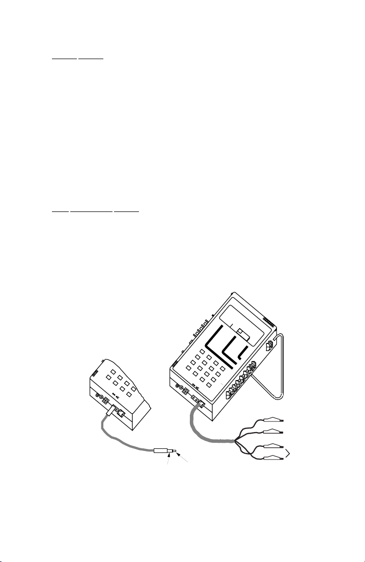
AM-48 Test Set (18-0015) Connection & Configuration
6-3
Printer Cables . There are two (2) types of cables used with printers.
The 48-0079 is used with the AM-47 Hand-Held Printer. The
48-0078 is used to connect with most other 25-pin female serial EIA
printers. The pin assignments of the male connector are:
2 = RCV
3 = XMIT
7 = GND
20 = Data Terminal Ready (+12V typical)
Figure 6-3 shows the connections for the AM-47 Hand-Held Printer.
See ¶7.39 for operating instructions for printing.
Line Connection Cables . The RJ-11 (modular) and three (3) Bantam
cables illustrated in Figures 3-4 and 3-5 are used for line connections.
Use these cables as required to connect the AM-48 to 2-wire or
4-wire lines. Figures 6-1 and 6-2 illustrate and define Modular and
Bantam line connections. Be sure to set Switch 10 (Figure 3-5) to the
appropriate position as indicated in the Figures.
Ameritec
2-WIRE
Set Switch 10 to <2W>
BANTAM-TO-BANTAM
DO NOT USE <RCV>
FOR 2-WIRE
PERSONAL TRANSMISSION TEST SET
QUIET
VOL
3 TONESWEEP
1004
SEND
VAR
PAR
L/F
∇
MON RCV
•
∇
PAR
NOISE
MON SND
TALK
IMPLS ØJTR
HOLD
∇
TERM
∇
BRDG
∇
TONE
•
∇
PULSE
ON HK
∇
∇
MODULAR
∇
2W
•
4W
∇
4W REV
7
MIC
8
PRT EAR
START
*
∇
DC
0
9
9V
C
#
CANCEL
STOP
4W/2W
∇
SND
4W
D
RCV
+
/
-
900Ω
600Ω
1
∇
2W
•
4W
∇
4W REV
4
7
5
MIC
8
PRT EAR
START
*
∇
DC
0
9
9V
#
STOP
4W/2W
∇
SND
4W
D
RCV
+
/
-
TONE
MEASURE
NOISE
∆
∇
JTR TRANS
FILTER
DAMP
2
6
C
CANCEL
OFF
∇
SEL
∇
3
∇
SEL
∇
A
ETR/NEXT
∇
SEL
∇
DTMF
MF
B
∇
ETR/PREV
SHIFT
•
SF SKP
∇
X TONE
NOR
∇
RCL/STO
•
∇
∇
PRINT
∇
S/N
15K
REL
SEND
∇
∇
MODEL AM-48
3K
C-MSG
PROG
ABS
∇
•
∇
T = Tip
R = Ring
ON
∇
•
ON/
∇
OFF
Green (T)
Red (R)
Yellow (T1)
NOT USED
Black (R1)
T
R
Black (R1)
Figure 6-1. 2-Wire AM-48 Line Connections
0015-S06
Page 71
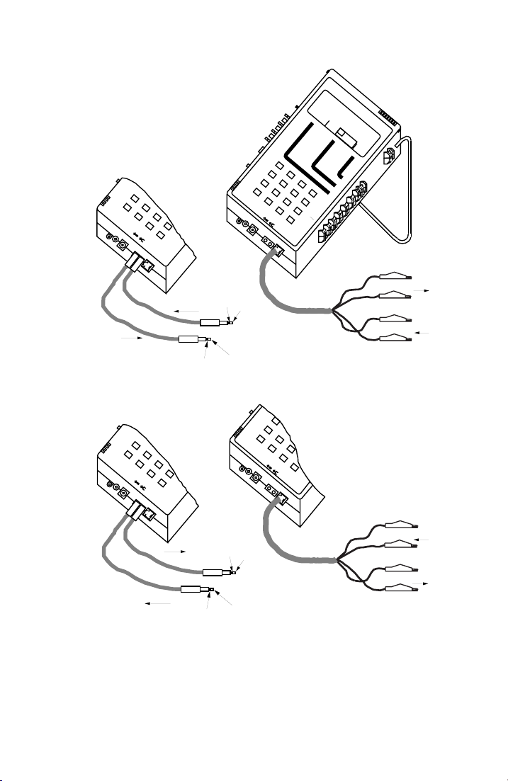
Connection & Configuration (18-0015) AM-48 Test Set
Ameritec
4-WIRE
Set Switch 10 to <4W>
BANTAM-TO-BANTAM
∇
2W
•
4W
∇
4W REV
7
MIC
8
PRT EAR
START
*
∇
DC
0
9
9V
#
CANCEL
STOP
4W/2W
∇
SND
4W
D
RCV
+
/
-
RECEIVE, <RCV>
SEND , <SND>
4-WIRE REVERSED (Frogged)
Set Switch 10 to <4W REV>
BANTAM-TO-BANTAM
∇
2W
•
4W
∇
4W REV
7
MIC
PRT EAR
8
START
*
∇
DC
0
9
9V
#
STOP
4W/2W
∇
SND
4W
D
RCV
+
/
-
C
C
CANCEL
MODULAR
R1
R
PERSONAL TRANSMISSION TEST SET
QUIET 1004 VAR
VOL
3 TONE SWEEP
SEND
PAR
L/F
∇
MON RCV
•
∇
PAR
MON SND
TALK
∇
TERM
∇
BRDG
∇
TONE
•
∇
PULSE
ON HK
∇
∇
900Ω
600Ω
1
∇
2W
•
4W
∇
4W REV
4
2
7
MIC
PRT EAR
5
8
START
*
∇
DC
0
9
9V
#
CANCEL
STOP
4W/2W
∇
SND
4W
D
RCV
+
/
-
NOISE
IMPLS ØJTR
HOLD
TONE
MEASURE
NOISE S/N
∆
∇
JTR
TRANS
15K
FILTER
ABS
REL
SEND
DAMP
∇
OFF
∇
∇
SEL
3
6
B
ETR/PREV
C
∇
∇
SEL
∇
A
ETR/NEXT
∇
SEL
∇
DTMF
MF
∇
SHIFT
•
SF SKP
∇
X TONE
NOR
∇
RCL/STO
•
∇
∇
PRINT
∇
T1
T
∇
2W
•
4W
∇
4W REV
4
MODULAR
7
MIC
8
PRT EAR
START
*
∇
DC
0
9
9V
#
STOP
4W/2W
∇
SND
4W
D
RCV
+
/
-
MODEL AM-48
3K
C-MSG
PROG
∇
•
∇
T = Tip
R = Ring
T1 = TIP 1
R1 = Ring1
T = Tip
R = Ring
T1 = TIP 1
R1 = Ring1
ON
∇
•
ON/
∇
OFF
Green (T1)
SEND , <SND>
Red (R1)
Yellow (T)
RECEIVE, <RCV>
Black (R)
SEND , <SND>
R
T
RECEIVE, <RCV>
T1
R1
Figure 6-2. 4-Wire AM-48 Line Connections
Green (T1)
RECEIVE, <RCV>
Red (R1)
Yellow (T)
SEND , <SND>
Black (R)
0015-S066-4
Page 72
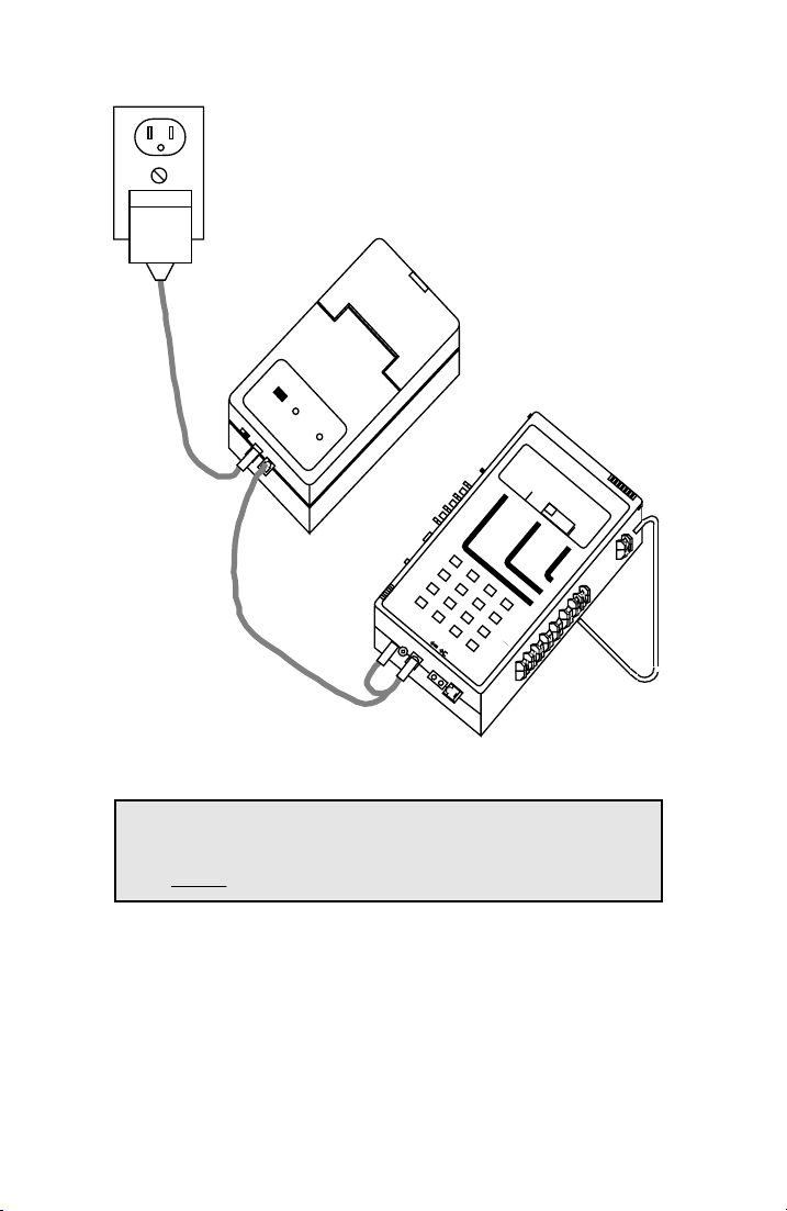
AM-48 Test Set (18-0015) Connection & Configuration
6-5
115 VAC
WALL JACK
AM-47
HAND-HELD PRINTER
AC ADAPTER
(70-0029)
Ameritec
HAND-HELD PRINTER • Model AM-47
PAPER
ADVANCE
OFF ON
POWER
POWER
9VDC
IN
SIGNAL
IN
PRINTER CABLE
(48-0079)
PAPER CUTTER
Am
eritec
VOL
∇
MON RCV
•
∇
MON SND
TALK
2
3
6
ETR/NEXT
B
ETR/PREV
C
CANCEL
D
PERSONAL TRANSMISSION TEST SET
QUIET 1004 VAR
3 TONE SWEEP
SEND
PAR
L/F
PAR
NOISE
IMPLS ØJTR
HOLD
TONE
MEASURE
SEL
∇
A
∇
SEL
∇
DTMF
MF
∇
SHIFT
•
SF SKP
∇
X TONE
NOR
∇
RCL/STO
•
∇
∇
PRINT
∇
AM-48
MODEL AM-48
ON
∇
NOISE S/N
∆
∇
•
JTR TRANS
ON/
∇
OFF
3K
15K PROG
C-MSG
FILTER
ABS
∇
REL
SEND
•
DAMP
∇
∇
OFF
∇
∇
SEL
∇
∇
SIGNAL
∇
TERM
∇
BRDG
∇
TONE
•
∇
PULSE
ON HK
∇
∇
900Ω
600Ω
1
∇
2W
•
4W
∇
4W REV
4
7
5
8
START
*
∇
DC
0
9
9V
#
STOP
4W/2W
∇
SND
4W
RCV
+
/
-
<PRT>
MIC
PRT EAR
<DC 9V>
LINE CONNECTION
CABLE(S) NOT SHOWN
Figure 6-3. AM-47 Hand-Held Printer Connection with AC Power
Note: The RJ-11 and Bantam jacks are wired in parallel, resulting
in an identical connection when either type of plug is used.
Do not use the <RCV> jack to connect 2-wire lines.
0015-S06
Page 73

Connection & Configuration (18-0015) AM-48 Test Set
AM-48 Interface with Line Connections . The position of Switch 10
(Figure 3-5) determines the connection of the AM-48 internal
circuitry to the 2-wire or 4-wire lines. The connections for the
different settings of Switch 10 are listed below:
<2W> Connects the internal measurement circuitry to the
signal generator across the 2-wire line at the <SND>
jack. The signal generator source impedance 600Ω or
900Ω (determined by Switch 11) terminates the line in
all signal generator modes except QUIET. In QUIET
mode, the line will be terminated only if Switch 13 is
set to <TERM>. Note that the
< RCV > jack is not used
to connect to 2-wire lines .
<4W> Connects the internal measurement circuitry to the
<RCV> pair, and the internal signal generator to the
<SND> pair.
<4W REV> Send and receive pairs (as defined above) are reversed.
See ¶6.4 and 6.5 for details about line termination impedance.
AM-48 is Polarity Insensitive . It does not matter which way the Send
pair or Receive pair of contacts are connected. The Send <SND> T
and R can be interchanged without affecting the measurement. The
Receive <RCV> T1 and R1 may also be switched without changing
the measurement.
For example, in Figure 5-1, which shows the loopback connections
for self-test, the connections could be changed as indicated below:
Figure 5-1 Connections Alternate Connections
RED (R) to BLACK (R1)
GREEN (T) to YELLOW (T1)
RED (R) to YELLOW (T1)
GREEN (T) to BLACK (R1)
0015-S066-6
Page 74

AM-48 Test Set (18-0015) Connection & Configuration
6
In general:
1. For 4-wire
a) Use the <SND> T and R (connecting either way) for
the Send contacts
b) Use the <RCV> T1 and R1 (connecting either way) for
the Receive contacts
2. For 2-wire, use <2W> T and R (connected either way). These
contacts are the same as <SND> for 4-wire.
6.4 600Ω/900Ω Line Termination Impedances
It is important that the line(s) be properly terminated with a matching
impedance. This paragraph gives instructions for terminating lines
with 600Ω or 900Ω impedance. To terminate lines with impedance
other than 600Ω or 900Ω connect the Ameritec Impedance Adapter
as per ¶6.5.
To terminate the line(s) correctly with 600Ω or 900Ω:
1. Choose either terminate or bridge mode:
a) Set Switch 13 to <TERM>, terminate mode, or
b) Set Switch 13 to <BRDG>, bridge mode, and terminate
the line with some other device (such as a modem) of
proper impedance.
2. Regardless of the method of termination, set Switch 11 to
<600Ω> or <900Ω> to match the impedance of the line.
Note: An incorrect Switch 11 setting results in about 1.8 dB error
in level and noise readings.
0015-S06
-7
Page 75
Connection & Configuration (18-0015) AM-48 Test Set
Switch 13 Settings . The connections for the settings of Switch 13 are
listed below:
<TERM>
Receive line terminated with a resistive impedance as
selected by Switch 11.
<BRDG> Receive line unterminated and bridged only with the
impedance of the measurement circuitry (>25KΩ) across
the receive pair.
Note: In 2-wire mode, the signal generator source impedance will
terminate the line with 600Ω or 900Ω with Switch 13 in
either <TERM> or <BRDG>. However, if SEND is in QUIET
mode, Switch 13 will be able to function. In 2-wire QUIET
send mode, setting Switch 13 to <BRDG> will disconnect the
signal generator from the send pair and the send pair source
impedance will be >25KΩ. There will be an error of 6 dB if
<BRDG> is incorrectly selected when the line should be
terminated with <TERM>.
Switch 11 Settings . The connections for the settings of Switch 11 are
listed below:
<600Ω> 600Ω applied across the Receive pair when Switch 13 is
set to <TERM>.
Send pair source impedance set at 600Ω.
<900Ω> 900Ω applied across the Receive pair when Switch 13 is
set to <TERM>.
Send pair source impedance set at 900Ω.
0015-S066-8
Page 76

AM-48 Test Set (18-0015) Connection & Configuration
6-9
6.5 Impedance Adapter
The Impedance Adapter (24-0005) is used:
1. To match the AM-48 to a user interface of
600Ω or 900Ω .
2. To match 4-wire split impedances .
See Figure 3-10 for an illustration of the Impedance Adapter; Figure
9-2 is the schematic diagram of the Impedance Adapter.
The Impedance Adapter is used to adapt the AM-48 to impedances of
75Ω, 135Ω, 150Ω, or 1200Ω. For example, high speed digital lines
typically have impedances of 75Ω, 135Ω, or 150Ω. A “THRU”
setting on the Impedance Adapter makes a straight through
connection resulting in a 600Ω or 900Ω termination inside the
AM-48.
To use the AM-48 with the Impedance Adapter:
1. Set AM-48 Switch 11 to <600Ω> and Switch 13 to <BRDG>.
2. Plug the Impedance Adapter into the AM-48 modular jack.
3. Plug a modular line cable into the jack on the Impedance
Adapter.
impedance other than
4. Connect the line cable to the 2-wire or 4-wire line per Figure 6-1
or 6-2.
5. Turn knob(s) on the Impedance Adapter to match the impedance
of the line:
a) For 2-wire, use only the upper knob.
b) For 4-wire, set the upper knob to match the Send pair
impedance and the lower knob to match the Receive
pair impedance.
0015-S06
Page 77
Connection & Configuration (18-0015) AM-48 Test Set
Note: The reading on the AM-48 display needs to be corrected
when the Impedance Adapter is used; see ¶7.41 for
instructions.
6.6 Configurations
There are three (3) basic AM-48 configurations to test 2-wire and 4-
wire telephone and data communication lines:
1. End-to-end - requiring two (2) AM-48’s
2. Loopback
3. Testing with responders
This paragraph describes the different configurations, explains how
they are used, and discusses the advantages and disadvantages.
Note: End-to-end and responder testing applies to either 2-wire or
4-wire. Loopback testing only applies to 4-wire.
End-to-end Testing . Measurements on telephone transmission lines
are usually made by applying an appropriate signal at one end of the
transmission line and then measuring the results at the other end of
the line. This configuration requires a test set at each end of the line
and is called “end-to-end” testing.
Figure 6-4 shows a 4-wire end-to-end configuration, making
measurements over a telephone network that normally connects two
(2) modems. Each AM-48 both sends and receives signals, sending a
signal over the <SND> pair of lines and measuring the signal received
over the <RCV> pair of lines.
End-to-end testing can also be done over 2-wire lines. The AM-48
on one end sends a signal, and the AM-48 on the other end measures
the received signal.
0015-S066-10
Page 78
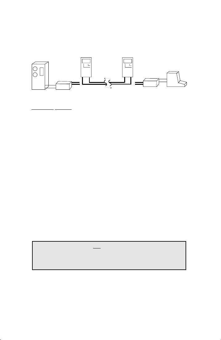
AM-48 Test Set (18-0015) Connection & Configuration
6
End-to-end testing is the most reliable for characterizing the near-to-
far and far-to-near impairments, but it has the disadvantage of
requiring two (2) test sets and an operator at each test site.
CPU
MODEM
AM-48
RCV
Telephone
Network
<RCV> <SND>
<SND>
<RCV>
AM-48
XMIT
RCVXMIT
MODEM
DTE
Figure 6-4. 4-Wire End-to-End Testing
Loopback Testing . The distant end of a 4-wire transmission line can
be looped back (1) manually, or (2) with a commandable loopback
device such as a Western Electric Model 829. The AM-48 at the near
end sends a signal which travels to the distant end where it makes a
U-turn and travels back to the AM-48, which measures the received
signal.
The advantage of this configuration is that it requires only one (1)
operator and test set at a central site. Although this method is more
convenient and less costly than end-to-end testing, it is also less
reliable. The disadvantage is that it does not characterize
transmission impairments in each direction. Instead of detecting
impairments, a loopback measurement could actually cover them up.
An apparently satisfactory loopback measurement may contain
impairments in each direction which cancel each other. Loopback
testing may be useful, providing its limitations are recognized.
Note: A loopback test can not be done on 2-wire because signals
can not be sent and measured simultaneously on the same
pair of lines.
To do a loopback test with a Western Electric Model 829:
1. Connect the AM-48 at the near end of the 4-wire line under test.
0015-S06
-11
Page 79

Connection & Configuration (18-0015) AM-48 Test Set
2. With Switch 8 (Figure 3-5), momentarily press <X TONE> to
send a 2713 Hz tone over the <SND> line. This will trip the
distant Model 829 into loopback.
3. Send the desired test signal with the AM-48 and make the
desired measurement of the looped-back signal.
4. After testing is finished, momentarily press <X TONE> to restore
the Model 829 to its normal, transparent state.
Testing with Responders . The use of multi-function responders
supplies most of the advantages of end-to-end testing with the added
advantage of not requiring an AM-48 at the far end of the system.
This configuration is similar to loopback testing except that the
responder can generate signals in addition to looping back. Unlike a
dedicated loopback device, responders can be used in 2-wire far-to-
near testing.
On 4-wire circuits, a DTMF commandable responder, such as the
Ameritec Model AM3-4, may be placed permanently at the distant
modem where it remains transparent until commanded by DTMF
signals sent from the AM-48 at the central site. In addition to
performing loopback, the responder can send various tones, allowing
for far-to –near tests as well as loopback tests.
EXAMPLE: 4-wire far-to-near and loopback tests for level and
frequency with an Ameritec AM3-4A or AM3-4B Responder:
1. Connect an AM-48 to the near end of a 4-wire facility and an
Ameritec Model AM3-4A or AM3-4B Responder at the far end.
A typical configuration is illustrated in Figure 6-5.
2. Use the AM-48 keypad to send the appropriate DTMF command
sequence to command the responder into milliwatt mode
(responder will generate 1004 Hz, 0 dBm signal). Measure the
received signal and note the level and frequency.
0015-S066-12
Page 80
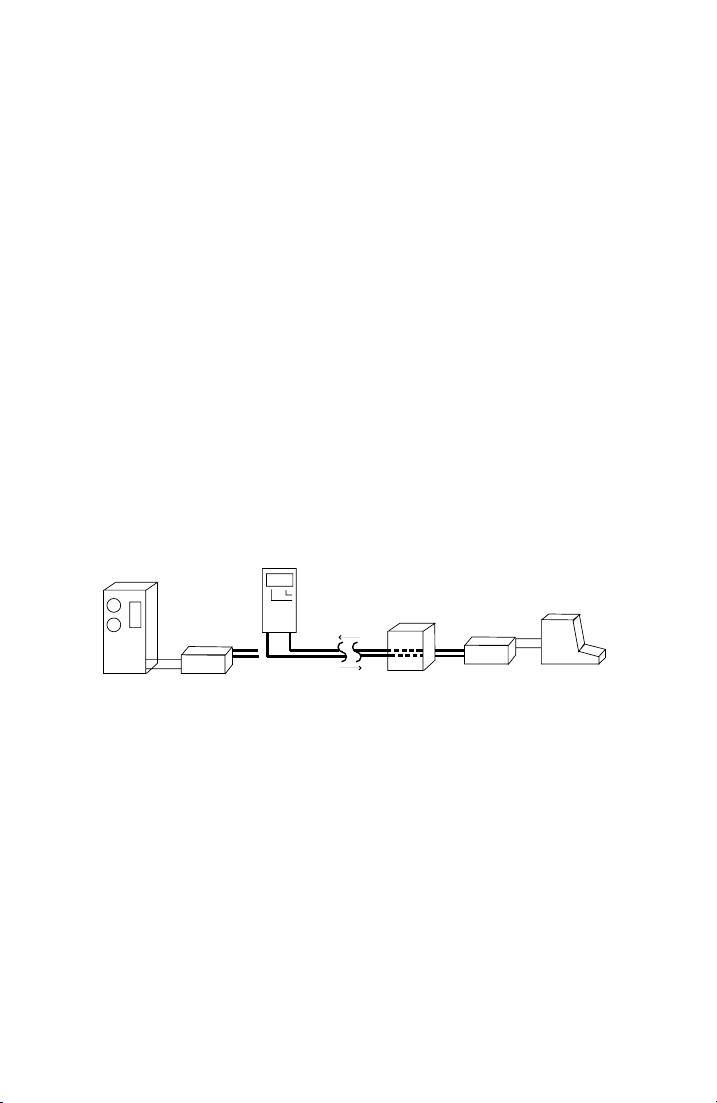
AM-48 Test Set (18-0015) Connection & Configuration
6-13
3. Use the AM-48 keypad to send a DTMF sequence to command
the responder into loopback.
4. Use the AM-48 to send a 1004 Hz tone @ 0 dBm. Measure the
loopback received level and frequency.
5. Use the AM-48 keypad to send a DTMF command sequence to
restore the responder to normal.
On a 2-wire network, dial access responders are very useful in
measuring far-to-near characteristics. An Ameritec AM3-2C
Responder (automatic milliwatt) or AM3-2A Responder can be
dialed up over the network path under test using the AM-48 keypad.
It can then be commanded with touch tone from the AM-48 to make
level measurements or send tones. The AM3-2C can perform far-to-
near level and frequency, idle channel noise, and noise with tone. In
addition to the AM3-2C functions, the AM3-2A can also perform far-
to-near gain slope and near-to-far level. A typical configuration is
illustrated in Figure 6-6.
Loopback Quiet
Send Tones
CPU
MODEM
AM-48
RCV
<RCV>
<SND>
Telephone
Network
Amputate
AM3-4A
Responder
XMIT
RCVXMIT
MODEM
DTE
Figure 6-5. 4-Wire Testing with Responder
0015-S06
Page 81
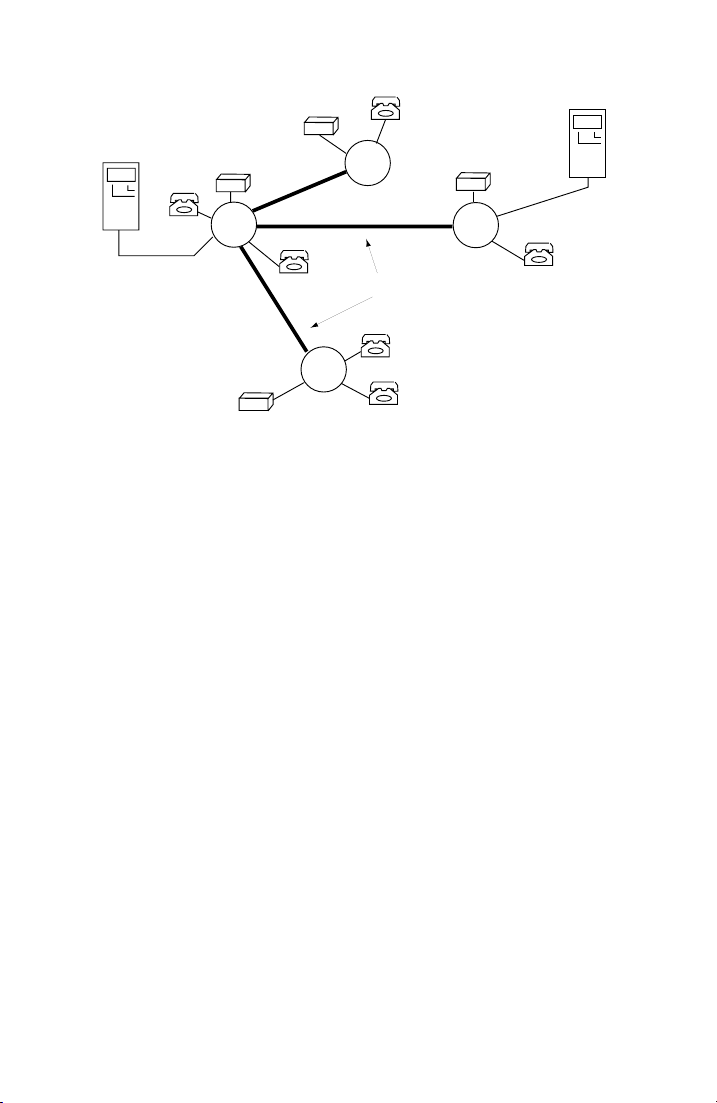
Connection & Configuration (18-0015) AM-48 Test Set
MW
AM-48
<SND>
AM3-2
2W RESPONDER
PBX
CO
FX
MW
TIE
TELEPHONE NETWORK
DISTANT
CO
LOCAL
CO
Figure 6-6. 2-Wire Network Testing with Responders
AM3-2
2W RESPONDER
PBX
AM-48
<SND>
0015-S066-14
Page 82

AM-48 Test Set (18-0015) Operating Instructions
7. OPERATING INSTRUCTIONS
Note: Set up the AM-48 per Section 6 before performing
operations in this section.
7.1 Introduction
The AM-48 operating instructions in this section are divided into five
(5) major subjects and associated paragraphs as listed below:
7.2 General Instructions and Notes
7.3 General Operating Notes
7.4 Figure Format
7.5 General Switch Setup
7.6 Multiple Use of Keys
7.7 Memory
7.8 General Procedure to Set New Parameter Values
7.9 Send (Generator) Modes and Parameter Settings
7.10 Type of Send Signals
7.11 Send Quiet
7.12 Set Parameters from Quiet Display
7.13 Send Momentary Variable Tones
7.14 Send 1004 Hz
7.15 Send Continuous Variable Tone
7.16 Send 3-Tone Slope
7.17 Send Variable Sweep
7.18 Send PAR Waveform
7.19 Send Momentary 2713 Hz Tone
7.20 General Measure Mode Notes
7.21 Accuracy of Measurements
7.22 Absolute and Relative Measurements
7.23 Special Measurement Requirements
7.24 Timed Tests
0015-S07
7-1
Page 83

Operating Instructions (18-0015) AM-48 Test Set
7.25 Measure Modes and Parameter Settings
7.26 Measure Level and Frequency
7.27 Measure Noise
7.28 Measure PAR
7.29 Measure Impulse Noise
7.30 Measure Notched Noise
7.31 Measure S.N Ratio
7.32 Measure Phase Jitter
7.33 Measure Amplitude Jitter
7.34 Measure Transients (Impulse Noise, Notched Noise,
Phase Hits, Gain Hits, and Dropouts)
7.35 Miscellaneous Operations
7.36 Store and Recall
7.37 Dialing
7.38 Talking
7.39 Printing
7.40 Auto Study Result Save
7.41 Impedance Adapter Measurement Corrections
7.42 Auto Calibrate
It is assumed in this section that the user is familiar with basic
AM-48 operation, having followed the self-test instructions of
Section 5. Instead of step-by-step procedures with full details, the
instructions refer to the figures, which summarize the information
needed to perform a test.
Read the general notes in ¶7.2 thru 7.10 and 7.20 thru 7.24 before
going to specific operating instructions.
0015-S077-2
Page 84

AM-48 Test Set (18-0015) Operating Instructions
3
7.2 General Instructions and Notes
¶7.3 thru 7.8 cover general instructions and notes. These paragraphs
should be read before doing a specific test or operation.
7.3 General Operating Notes
Keys . Do not be afraid to experiment with the keys. The AM-48 will
not accept an “illegal” or meaningless keystroke. If an out-of-
tolerance value is entered in a user-programmable variable field, the
display will default to an acceptable value.
Displays .
1. The units of measurement appear at the top of the display, above
the value. Time and count units are not shown, but are given in
the table associated with the corresponding display.
2. Display decimal points will flash when batteries are low.
3. Displays of “OVER” or “UNDR” indicate the signal being
monitored is too high or low to be read.
4. Depending on the mode, there may be multiple displays through
which one can scroll. All displays accessible form each mode
are shown in the figures.
5. To quickly go to the initial display from another display in a
scroll, momentarily exit and then re-enter the same mode by
moving the cursor. See the example in ¶5.7.
Check List . Go through the following check list to cover important
points while performing any operation:
1. Look at the cursor positions on the menus. These indicate what
SEND and MEASURE mode is selected and what noise-weighting
filter is selected.
0015-S07
7-
Page 85

Operating Instructions (18-0015) AM-48 Test Set
2. Note the color-coding and framing of the cursor menus and use
these to determine if a filter is needed (orange functions) or a
holding tone is needed (within the rectangle) for the present
position of the cursors. See ¶3.7 and 7.23 for explanation of
menu framing.
3. Note the setting of Switch 2, the Display Select Switch. This
will indicate what is being viewed on the display. <ABS> or
<REL> indicate that the display is viewing the MEASURE mode;
while <SEND> indicates the display is viewing the SEND mode.
4. Note the setting of Switch 7. This indicates whether the
keyboard is connected to dial (<DTMF> or <MF>) or to operate
the auxiliary functions (<SHIFT>).
7.4 Figure Format
Figures 7-1 thru 7-9 show the display(s) which can be accessed from
the indicated SEND or MEASURE mode. The position of the menu
cursor, the necessary switch settings, and other pertinent information
is indicated in each figure. A detailed description of the arrangement
of the figures is listed below.
1. The
display fields are shown with three (3) types of characters.
The characters are illustrated at the bottom of some figures in a
table labeled “DISPLAY CHARACTER CODE”. The meanings of
the characters are:
Solid : These letters and numbers are fixed and will
a)
always appear just as they are shown. They are
abbreviations for the names of the parameters.
0015-S077-4
Page 86

AM-48 Test Set (18-0015) Operating Instructions
5
b) Cross-hatched : These characters represent values that
variable but cannot be changed by the user from
are
the display in which they are shown. In the SEND
modes these indicate the level and frequency being
sent; in the MEASURE mode, they give the measured
values.
c)
Plain : These characters represent parameter values
variable and can be changed by the user from
that are
the display in which they are shown.
2. Next to each display is a
table of information and instructions
which apply to the adjacent display. The middle column of the
table gives the range of acceptable values to enter for a variable
parameter or the range of values that can be measured.
3. The SEND or MEASURE
cursor setting is shown darkened on the
menu just as it appears at the bottom of the AM-48 display.
There are always three (3) cursors in view, although only one (1)
is shown in each of the figures. The positions of the other two
(2) cursors will depend upon the test configuration and setup.
4. The
switch settings are indicated next to the location of the
switches in the illustration of the AM-48 at the bottom of the
figure. Only the necessary switch settings for the test under
consideration are shown. Set the other switches as appropriate,
according to the test configuration and setup.
5. The
notes on the left at the bottom of the figures relate to the
displays. The notes on the right relate to the switches and
keyboard.
0015-S07
7-
Page 87

Operating Instructions (18-0015) AM-48 Test Set
6. At the bottom of some figures, an alternate display(s) is
illustrated, e.g., “OVER” or “UNDR”, which may be displayed to
call attention to an out-of-tolerance condition.
7.5 General Switch Setup
See ¶3.5 for a summary of the use of each switch. Refer to Figure
3-5 for switch identification number (see ¶3.2). Follow the
guidelines below for proper switch setup.
1. Make connections and set Switches 10, 11, and 13 per the line
interface. See ¶6.3 thru 6.5 for details.
2. Connect and turn on power with Switch 1 per Section 4.
3. Switch 2, Display Select, determines what appears on the
display. Set Switch 2 to the desired position:
a) <ABS> to view MEASURE display (see ¶7.22 for use of
<REL> position).
b) <SEND> to view SEND display
4. Use Switches 5 and 6 to set the display cursor to the desired
SEND and MEASURE modes, and Switch 4 to select a noise-
weighting filter, if required (see Table 7-5).
5. Set Switch 7 to <SHIFT> to enable auxiliary keyboard functions
to:
a) Scroll through multiple displays
b) Use keyboard to change a parameter value
c) Send momentary user-programmed tone from
keyboard in
d) Do Store/Recall
e) Run a transient test
f) Do auto calibrate
Leave Switch 7 in <SHIFT> except when dialing.
QUIET mode
0015-S077-6
Page 88

AM-48 Test Set (18-0015) Operating Instructions
6. Use Switches 3, 14, and 15 to connect a speaker or earphone to
the desired monitoring point and adjust volume. As a rule, leave
Switch 3 <OFF>.
7. Leave Switch 8 in <NOR> unless it is desired to avoid
transmission of tones in the signaling frequency band (in which
case, set to <SF SKIP>).
8. Use Switch 9 as required to Store and Recall setups or output
information to the Printer port. See ¶7.36 and 7.39.
9. Leave Switch 12 in <ON HK> except to go
dial access lines. <TONE> and <PULSE> are
off-hook on 2-wire
off-hook positions
and connect a 200Ω DC short across T and R.
Display Damping Switch . Set Switch 3 to <OFF> for a normal
display update of four (4) times per second, or to <DAMP> to slow the
display update to two (2) times per second.
Switch 3 also affects the monitor point of the speaker. Refer to the
upper part of Figure 9-1 with the descriptions below:
1. With Switch 14 set to <MON RCV> and Switch 3 set to <OFF>,
the speaker monitors the signal on the <RCV> jack (T1, R1) for
4-wire operation.
2. With Switch 14 set to <MON RCV> and Switch 3 set to <DAMP>,
the speaker monitors the received signal (from T1, R1 in 4-wire
operation, or T, R in 2-wire operation) at a point following the
noise weighting filter, notch filter (if in use), and auto-ranging
amplifiers. This is particularly useful for audibly monitoring the
residual noise in notched noise and S/N ratio measurements.
0015-S07
7-7
Page 89
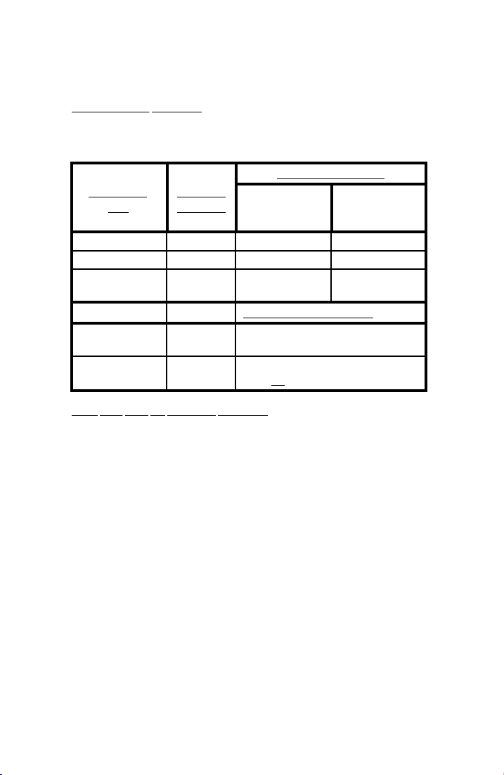
Operating Instructions (18-0015) AM-48 Test Set
7.6 Multiple Use of Keys
Multi-Function Keyboard . See Table 7-1 for different uses of the
keyboard, per the setup (switch numbers per Figure 3-5).
Table 7-1. Setup Requirements for Different Keyboard Applications
SWITCH 12 POSITION
KEYBOARD
USE
Dial DTMF <DTMF> <TONE> <ON HK>
Dial MF <MF> <TONE> <ON HK>
Dial PULSE <DTMF> or
Send Momentary
Variable Tone
Set Parameter
Values
Keys with Two (2) Auxiliary Functions . The (*) and (#) key each
have two (2) auxiliary functions. The [START]/[∆], on the (*) key,
and [STOP]/[∇], on the (#) key, are enabled per the setup.
SWITCH 7
POSITION
<MF>
<SHIFT> From QUIET SEND Display
<SHIFT> Displays in Figures 7-1 thru 7-8 with
2-WIRE
OFF-HOOK
(loop current)
<PULSE> _ _ _ _ _
DISPLAY REQUIREMENTS
plain (not cross-hatched) characters
2-WIRE
ON-HOOK
OR 4-WIRE
The [START] and [STOP] functions only operate from certain displays
in a timed test; see ¶7.24.3.
See ¶7.8.2 and .3 for explanation of the use of the [∆] and [∇]
functions. When the [∆] or [∇] key is pressed continuously, the
“auto-repeat” feature is enabled and repeatedly steps a parameter
value at 10 times the normal step. Table 7-2 lists the momentary and
continuous press steps.
0015-S077-8
Page 90

AM-48 Test Set (18-0015) Operating Instructions
9
Table 7-2. Steps for [∆] and [∇] Keys
PARAMETER MOMENTARY
PRESS STEP
Frequency 10 Hz 100 Hz
Level 0.1 dB 1.0 dB
Time 0.1 minute 1.0 minute
Note that in changing a level, the [∆] key steps mathematically more
positive and the [∇] key steps mathematically more negative . Foe
example, if a negative level is stepped down with the [∇] key, the
value of the number itself will become larger.
CONTINUOUS
PRESS STEP
7.7 Memory
Parameter Values Stored in Memory . Some user-programmable
parameter values are stored in
non-volatile memory . Table 7-3 lists the variable parameters and
in
indicates in which memory they are stored. General information
about the two (2) types of memory is given below:
Volatile Memory . User-set values stored here will be stored as
1.
long as the AM-48 power is on or until changed by the user.
When power is turned off or times out (after turning on with the
momentary power switch), the user-set volatile memory values
will be lost and revert to the
volatile memory and others are stored
default values.
2. Non-Volatile Memory . Values stored here will stay stored even
if AM-48 power is turned off. They will remain until changed
to another value by the user. Also stored in non-volatile
memory are the results and the parameter settings of the last
timed impulse noise or transient test. Note that the timed test
information is not stored in non-volatile memory unless the test
is actually run.
0015-S07
7-
Page 91

Operating Instructions (18-0015) AM-48 Test Set
In order to allow the transfer of timed test information into non-
volatile memory, the AM-48 power will not time-out during a
timed study. The time-out timer restarts at the end of a timed
study.
Level Display . There is only one level setting and it is stored in
volatile memory. For convenience, the level display that shows this
value can be accessed from any SEND display. The level display is
always the second display in the scroll. To access the level display:
1. Set Switch 2 to <SEND>.
2. Set Switch 7 to <SHIFT>.
3. Rock Switch 6 to select any SEND mode.
4. Press [ETR/NEXT]
5. Level display will appear.
Remember that when the level value is changed, it changes the level
for all SEND signals, except for dialed tones (see ¶7.12.3 for
instructions to set touch tone level). When power is turned off, the
send level always defaults to 00.0 dBm. The level for dialed tones,
however, is stored in non-volatile memory.
Store/Recall . Up to 10 test setups, including parameter values, can be
stored in non-volatile memory. A stored test setup can be recalled,
avoiding the need to set cursors and re-enter parameter values for a
routine test. See ¶7.36 for instructions.
0015-S077-10
Page 92
AM-48 Test Set (18-0015) Operating Instructions
Table 7-3. User-Programmable Parameter Values Stored in Memory
VOLATILE MEMORY
PARAMETER DEFAULT LEVEL
Level 00.0 dBm
Variable Frequency 1004 Hz
Variable Sweep Start Frequency 204 Hz
Stop Frequency 19,904 Hz
Step 100 Hz
Rate 1.0 sec
Jitter Bandpass Range 20 Hz – 300 Hz
NON-VOLATILE MEMORY
PARAMETER FACTORY SETTINGS
Dial Level (DTMF and MF) -10.0 dBm
Blanking Interval 125 ms
Time Off with Momentary Power 16 minutes
10 Momentary Frequencies
Not Applicable
(with Volatile Memory Level)
10 Test Setups
Not Applicable
(Stored on Number Keys
using <RCL/STO>)
Timed Test Parameters
Not Applicable
Duration of Timed Test
Impulse Noise Delta
Impulse Noise Threshold
Phase Hit Threshold
Gain Hit Threshold
Timed Test Results
Not Applicable
Time Elapsed
Low Impulse Count
Middle Impulse Count
High Impulse Count
Noise
Phase Hit Count
Gain Hit Count
Dropouts
Phase Locked Loop Frequency
0015-S07
7-11
Page 93
Operating Instructions (18-0015) AM-48 Test Set
7.8 General Procedure to Set New Parameter Values
Note: Set Switch 7 to <SHIFT> to enable the keys to perform the
auxiliary functions.
See ¶7.36 for instructions to store new parameter values for future
use.
Items 2, 3, 4, 5, 7, and 8 shown in Figure 3-6 are the auxiliary
keyboard functions that are used together with the number keys to set
new parameter values. ¶3.6 explains how these keys are used.
See ¶5.7, Steps N thru HH, for an example of setting new parameter
values. To summarize, there are three (3) procedures used to set new
parameter values (confirm Switch 7 in <SHIFT>).
Scroll Through the Displays . To view the displays without
1.
making any changes in parameter values:
(a) Press [ETR/NEXT] to go to the next display.
(b) Press [ETR/PREV] to go to the previous display.
2. Set a New Parameter Value Using the Number Keys.
(a) Press any number key or the [±] key to clear the
display of the old parameter value and start writing a
new value on the display.
Note: Now the [∆] and [∇] keys will not work.
Finish writing the new value with the number keys.
b) If a mistake is made in Step a), press [CANCEL] to
clear the display and view the old value.
c) After using the number keys to write a new value in
Step a), press either [ETR/NEXT] or [ETR/PREV] to
enter the new value into memory, replacing the old
value.
0015-S077-12
Page 94
AM-48 Test Set (18-0015) Operating Instructions
3
Note: Now [CANCEL] will not work.
d) Use Step1 to go to another display.
3. Set a New Parameter Value Using the [∆] and [∇] Keys.
a) Press [∆] and/or [∇] to step the displayed parameter
value up or down to a new value. To step in
increments 10 times the normal increment, hold the
key down continuously. See Table 7-2 for step values.
The new value displayed is entered directly into
memory, replacing the old value.
b) The [CANCEL] key will
value directly replaces the old value in memory.
c) [±] can
d) Use Step1 to go to another display.
not be used to change the sign because it will
clear the display (see Step 2a).
not work here because the new
7.9 Send (Generator) Modes and Parameter Settings
Paragraphs 7.10 thru 7.19 discuss the SEND modes.
Note: For all SEND modes, set Switch 8 to <SF SKIP> to prevent
sending tones in the signaling band of 2450 Hz to 2750 Hz
(2130 Hz to 2430 Hz for AM-48E). Set Switch 8 to
<NOR> to allow all frequencies to be sent.
7.10 Types of Send Signals
The AM-48 Send signals can be classified according to their
duration. The three (3) types of Send signals are:
1. Momentary
2. Continuous
3. Stepped (Slope and Sweep)
0015-S07
7-1
Page 95

Operating Instructions (18-0015) AM-48 Test Set
To send a variable
set the level and frequency per instructions in ¶7.12.1 and 7.12.2.
Send the frequency from the QUIET SEND display by pressing the
number to which the tone is assigned. Momentarily press Switch 8 to
<X TONE> to send
To send a variable continuous tone, set the SEND cursor to VAR and
set the desired level and frequency per ¶7.15.
To send
send continuous PAR, set the SEND cursor to PAR (¶7.18).
To send a pre-programmed set of slope frequencies, set the SEND
cursor to 3TONE (SLOPE
To send variable sweep set the SEND cursor to SWEEP (¶7.17).
continuous 1004 Hz, set the SEND cursor to 1004 (¶7.14). To
momentary tone, set the SEND cursor to QUIET and
momentary 2713 Hz tone (¶7.19).
for the AM-48E) (see ¶7.16).
7.11 Send Quiet
1. See Figure 7-1. Set switches per the SWITCH SETUP illustration
and the SEND cursor per the menu illustration.
2. A Quiet termination display will appear, “_ _ _ _ _ _ _ _”,
confirming that the AM-48 is quiet terminated.
0015-S077-14
Page 96
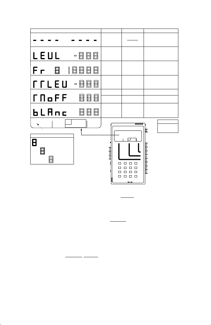
AM-48 Test Set (18-0015) Operating Instructions
5
DBM
QUIET DISPLAYS
•
HZ
TOUCH TONE
LEVEL "TTLEV"
NAME
QUIET
TERMINATION
LEVEL
"LEVL"
FREQUENCY
"FR"
ACCEPTABLE VALUES
10.0 to -50.0 dBm
200 to 19,999 Hz
7.0 to -50.0* dBm
TIME OFF
QUIET 1004 VAR
QUIET darkened
PAR
HOLD
L/F
NOISE NOISE S/N
TONE
PAR3 TONE SWEEP
IMPLS ØJTR JTR TRANS
∆
∇
DISPLAY CHARACTER CODE
Parameter Name (Fixed)
•
Key from which Programmed
Tone is Sent
User-Entered Value
See ¶7.11, 7.12, and 7.13 for instructions.
See ¶7.8 for general procedure to set new parameter values.
3K C-MSG
15K PROG
with momentary power
switch on "TMOFF"
BLANKING INTERVAL
"BLANC"
1 to 255* minutes
1 to 255* millisec (ms)
Ameritec
PERSONAL TRANSMISSION TEST SET
HOLD
QUIET 1004 VAR
L/F
NOISE NOISE S/N
TONE
PAR
PAR3 TONESWEEP
IMPLS ØJTR JTR TRANS
SEND MEASURE FILTER
VOL
∇
MON RCV
MON SND
•
∇
TALK
∇
TERM
∇
BRDG
∇
TONE
PULSE
•
∇
ON HK
∇
900Ω
21 A3
600Ω
∇
54 B6
∇
2W
4W
•
87 C9
4W REV
∇
0*D#
STOPSTART
∇
∇
MIC
4W/2W
SND4WRCV
PRT EARDC9V
SWITCH SETUP
Figure 7-1. Parameter Settings from QUIET SEND Display
0
MODEL AM-48
∆
∇
ETR/NEXT
ETR/PREV
CANCEL
+/-
ON/
OFF
3K C-MSG
15K PROG
ABS
REL
SEND
DAMP
OFF
SEL
SEL
SEL
MF
DTMF
SHIFT
SF SKP
NOR
X TONE
RCL/STO
PRINT
NOTES
Press key ([0] to [9]) to momentarily
send user-programmed tone.
Set level for all tones sent (except
dialed tones.
10 displays.
Set frequencies for tones on keys
[0] to [9].
Set level for DTMF or MF
tones dialed.
Power stays on.
Unused AM-48 powers down
after this time.
For Impulse and Transient tests
Standards:
143ms Bell 41009
125ms IEEE
FACTORY SETTINGS
*
TTLEV
ON
TMOFF
∇
•
BLANC
∇
∇
•
<SEND>
∇
∇
∇
∇
∇
∇
∇
∇
∇
Set QUIET
∇
•
<SHIFT>
∇
∇
•
∇
∇
∇
-10.0 dBm
16 minutes
125 ms
7.12 Set Parameters from Quiet Display
There are a total of 15 displays in the QUIET SEND mode. The third
display in Figure 7-1, “FR 8 18888”, represents 10 different displays,
from “FR 0 18888” to “FR 9 18888”.
See Figure 7-1 for all parameter settings in this paragraph. Set
switches per the SWITCH SETUP
per the menu illustration.
0015-S07
illustration, and set the SEND cursor
7-1
Page 97

Operating Instructions (18-0015) AM-48 Test Set
1. Set Level (see Figure 7-1 and ¶7.8).
a) Go to “LEVL” display.
b) Set desired level value (default value is 00.0 dBm).
c) New level value is stored in volatile memory.
Set Up to 10 Frequencies , sent with number keys from QUIET
2.
display (see Figure 7-1 and ¶7.8).
a) Go to desired “FR” display - - one (1) of 10.
b) The number after “FR” identifies the number key onto
which the frequency is programmed.
c) Set desired frequency value.
d) This value is stored in non-volatile memory.
e) Repeat Steps a) and c) for other frequencies as desired.
Set Touch Tone Level (see Figure 7-1 and ¶7.8).
3.
a) Go to “TTLEV” display.
b) Set desired level value for DTMF and MF dialing.
c) Recommended level (factory setting) is –10.0 dBm.
d) This value is stored in non-volatile memory.
Set Time Off : operates when power is turned on with the
4.
momentary power switch (see Figure 7-1 and ¶7.8).
a) Go to “TMOFF” display.
b) Set desired time value.
c) This value is stored in non-volatile memory (factory
setting is 16 minutes).
d) This time is when the AM-48 will turn off after the
last key or switch activity, if the unit has been turned
on with the momentary power switch.
0015-S077-16
Page 98
AM-48 Test Set (18-0015) Operating Instructions
e) Note that the AM-48 will
“0” is set. A time of “0” is not a desirable setting
when using batteries.
5.
Set Blanking Interval (see Figure 7-1 and ¶7.8).
a) Go to “BLANC” display.
b) Set desired blanking interval value.
c) This value is stored in non-volatile memory (factory
setting is 125 ms).
d) The meaning of the blanking interval for timed tests is
explained in ¶8.9.
e) Note the Bell and IEEE standard settings listed in
Figure 7-1.
not turn itself off if a time of
7.13 Send Momentary Variable Tones
1. With the switches and cursor set per Figure 7-1, program desired
frequencies on the number keys per ¶7.12.2.
2. The level of the tone sent is the value in the “LEVL” display,
stored in volatile memory (factory setting is 125 ms).
3. Go to the QUIET termination display, “_ _ _ _ _ _ _ _”.
Note: First select “SEND 1004” and then step backwards to select
QUIET termination.
4. Press the appropriate number key; [0], [1], [2], . . . . [9], to send
the desired frequency.
5. The tone will be sent for as long as the key is held down.
0015-S07
7-17
Page 99
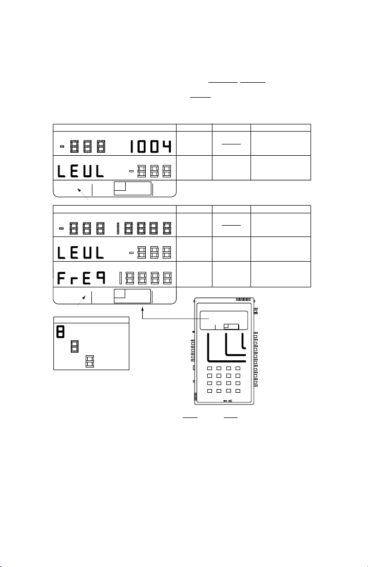
Operating Instructions (18-0015) AM-48 Test Set
7.14 Send 1004 Hz
1. See Figure 7-2. Set switches per the SWITCH SETUP illustration,
and set the SEND cursor per the lower menu illustration.
2. Go to the “LEVL” display and set the desired level value.
DBM
DBM
QUIET 1004 VAR
1004 HZ TONE DISPLAYS
•
L/F
NOISE NOISE S/N
PAR
PAR3 TONE SWEEP
IMPLS ØJTR JTR TRANS
1004 darkened
TONE
HOLD
HZ
•
3K C-MSG
∆
15K PROG
∇
VARIABLE TONE DISPLAYS
DBM
DBM
•
HZ
•
HZ
QUIET 1004 VAR
L/F
NOISE NOISE S/N
PAR
PAR3 TONE SWEEP
IMPLS ØJTR JTR TRANS
HOLD
TONE
VAR darkened
DISPLAY CHARACTER CODE
Parameter Name (Fixed)
•
Key from which Programmed
Tone is Sent
User-Entered Value
See ¶7.8 for general procedure to set new parameter values.
3K C-MSG
∆
15K PROG
∇
Figure 7-2. Parameter Settings from 1004 Hz and VAR Tone Send Displays
NAME
"1004" HZ
TONE
LEVEL
"LEVL"
NAME
VARIABLE
TONE
LEVEL
"LEVL"
FREQUENCY
"FREQ"
Ameritec
PERSONAL TRANSMISSION TEST SET
QUIET 1004 VAR
VOL
∇
MON RCV
MON SND
•
∇
TALK
∇
TERM
∇
BRDG
∇
TONE
PULSE
•
∇
ON HK
∇
900Ω
600Ω
∇
∇
2W
4W
•
4W REV
∇
MIC
PRT EARDC9V
ACCEPTABLE VALUES
10.0 to -50.0 dBm
ACCEPTABLE VALUES
10.0 to -50.0 dBm
200 to 19,999 Hz
SWITCH SETUP
MODEL AM-48
HOLD
L/F
NOISE NOISE S/N
TONE
∆
PAR
PAR3 TONESWEEP
IMPLS ØJTR JTR TRANS
∇
SEND MEASURE FILTER
21 A3
ETR/NEXT
54 B6
ETR/PREV
87 C9
CANCEL
0*D#
STOPSTART
+/-
∇
∇
4W/2W
SND4WRCV
Send Level of 1004 Hz
constant tone.
Set level for all tones sent (except
dialed tones).
Send Level and Frequency of
variable constant tone.
Set level for all tones sent (except
dialed tones).
Set frequency for variable
constant tones.
ON
∇
•
∇
ON/
OFF
3K C-MSG
15K PROG
∇
ABS
REL
•
<SEND>
SEND
∇
∇
DAMP
OFF
∇
∇
SEL
∇
∇
SEL
∇
∇
SEL
∇
Set 1004 or VAR
∇
MF
DTMF
•
<SHIFT>
SHIFT
∇
∇
SF SKP
NOR
•
X TONE
∇
∇
RCL/STO
∇
PRINT
NOTES
NOTES
0015-S077-18
Page 100

AM-48 Test Set (18-0015) Operating Instructions
9
7.15 Send Continuous Variable Tone
1. See Figure 7-2. Set switches per the SWITCH SETUP illustration,
and set the SEND cursor per the lower menu illustration.
2. Go to the “LEVL” display and set the desired level value.
3. Go to the “FREQ” display and set the desired frequency value.
7.16 Send Set of Slope Tones
1. See Figure 7-3. Set switches per the SWITCH SETUP illustration,
and set the SEND cursor per the upper menu illustration.
2. Go to the “LEVL” display and set the desired level value.
3. Go to the initial display and note that the frequencies 404 Hz,
1004 Hz, and 2804 Hz (404 Hz, 1004 Hz, 2004 Hz, and 3004 Hz
for AM-48E) are sent in a cycle @ 5 seconds.
0015-S07
7-1
 Loading...