

Page 1
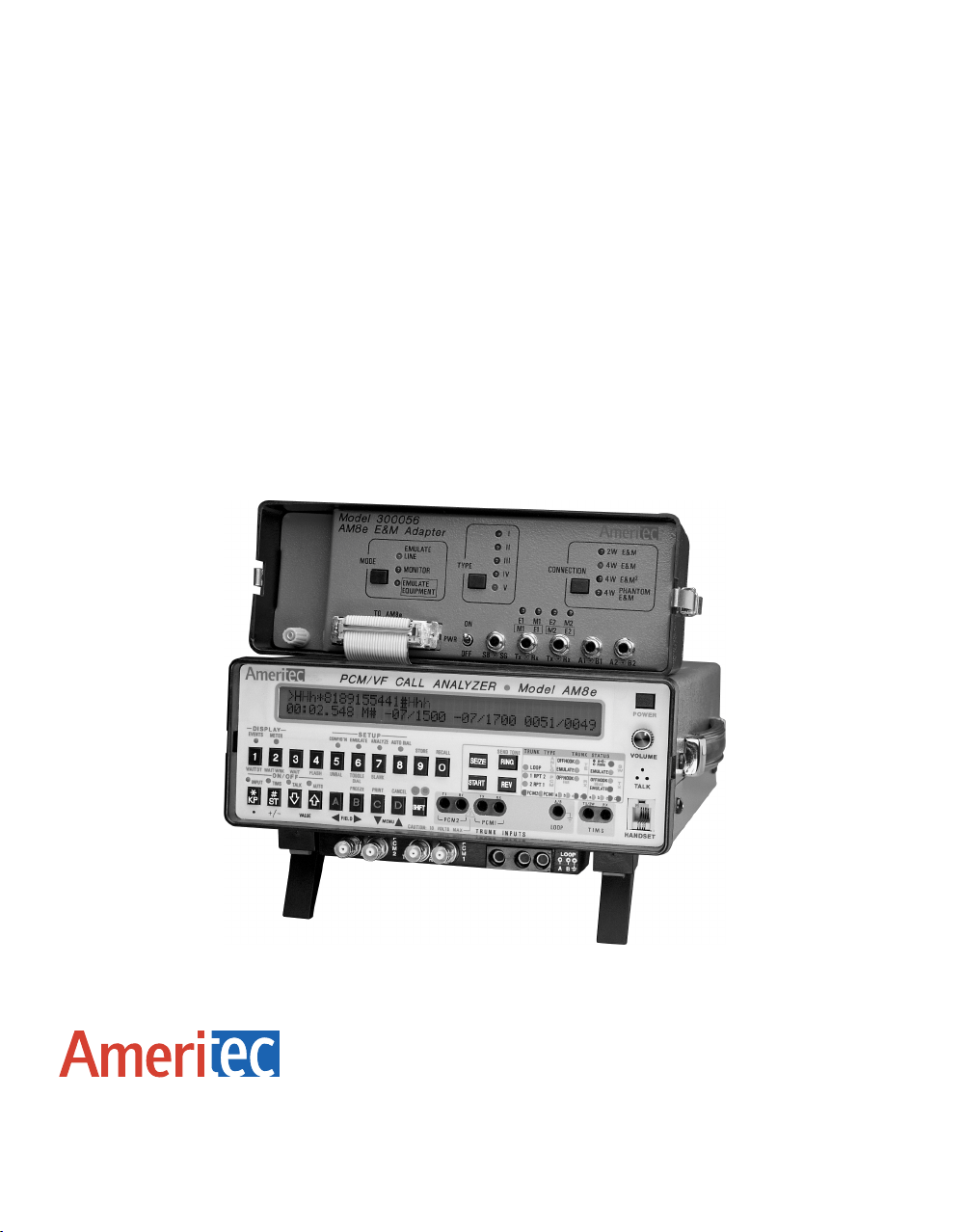
Model 30-0056
AM8e E&M Adapter
(for the Model AM8e PCM/VF Call Analyzer)
Instruction Manual
Page 2

Model 30-0056
AM8e E&M Adapter
(Used with Model AM8e PCM/VF Call Analyzer)
Instruction Manual
October 18, 2000
Technical Data Subject to
Change without Notice
760 Arrow Grand Circle
Covina, CA 91722 USA
TEL 626.915.5441
FAX 626.915.7181
www.ameritec.com
For extra copies of this manual,
order Part No. 18-0044
© 2000 Ameritec Corporation
Page 3

Record of Revisions
00 August, 1992 Preliminary Issue.
01 October, 1992 Original Release.
A May, 1993 Minot formatting changes.
B April, 1994 Revision. New cover. Minor adjustments and spelling corrections.
B1 June, 1995 Updated logos. Minor revisions.
B2 June, 1997 Updated logos, formatting corrections.
C October 18, 2000 Updated electronic copy, reformatted.
This manual was produced on a Power Macintosh using MS Word 6.0 and Adobe Illustrator
6.0.1.
October 18, 2000 0044-TPG.C_ 64
ii
Page 4

Model 300056 AM8e E&M Adapter (18-0044) Table of Contents
Table of Contents
1. INTRODUCTION.......................................................................................................1
1.1 Ameritec AM8e PCM/VF Call Analyzer .....................................................................1
1.2 AM8e Model 300056 E&M Adapter ..........................................................................2
1.3 AM8e Protocol Table Development Guide and Disk.....................................................2
1.4 Overview of E&M Test Configuration ........................................................................3
2. OPERATION OF THE E&M ADAPTER .........................................................................4
2.1 Front Panel Controls and Indicators..........................................................................4
2.1.1 PWR ON/OFF (Power ON/OFF Switch)...............................................................5
2.1.2 MODE (Mode Selector Switch) ..........................................................................5
2.1.3 MODE Indicators (Mode-Selected Indicators) .......................................................5
2.1.4 TYPE (E&M Type-Select Switch) .......................................................................5
2.1.5 TYPE Indicators (E&M Type Indicators) ..............................................................5
2.1.6 CONNECTION (Connection-Type Switch) ...........................................................6
2.1.7 CONNECTION Indicators (Connection-Type Indicators).........................................6
2.1.8 E1/M1, and E2/M2 Indicators (Active Status of E&M Signals) ..................................6
2.2 Connection to the Call Analyzer...............................................................................6
2.2.1 TO AM8e (AM8e Interface Connection)...............................................................6
2.3 Connections to Test Leads .....................................................................................7
2.3.1 SB/SG Connection .........................................................................................8
2.3.2 Tx/Rx for E1/M1.............................................................................................8
2.3.3 Tx/Rx for E2/M2.............................................................................................9
2.3.4 A1/B1 VF Connector .......................................................................................9
2.3.5 A2/B2 VF Connector .......................................................................................9
2.3.6 CO Ground Terminal.......................................................................................9
2.4 Setting the Operating Conditions ...........................................................................10
2.5 Remote Control of E&M Adapter............................................................................12
2.5.1 Remote Setup (ADP Command)......................................................................12
2.5.2 Remote Status (RADP Command) ...................................................................13
2.6 Call Analyzer Display and Bit Indicators ..................................................................13
0044-TOC.C_196 October 18, 2000
iii
Page 5

Table of Contents (18-0044) Model 300056 AM8e E&M Adapter
3. E&M SIGNALING DESCRIPTION ..............................................................................14
3.1 Connection Types ..............................................................................................15
3.1.1 2-wire E&M .................................................................................................16
3.1.2 4-wire E&M .................................................................................................16
3.1.3 4-wire E&M
2
................................................................................................16
3.1.4 Phantom E&M .............................................................................................16
3.2 E&M Trunk Types...............................................................................................18
3.2.1 E&M TYPE I ................................................................................................ 18
3.2.2 E&M TYPE II ...............................................................................................18
3.2.3 E&M TYPE III ..............................................................................................19
3.2.4 E&M TYPE IV.............................................................................................. 20
3.2.5 E&M TYPE V...............................................................................................20
APPENDIX A..............................................................................................................22
A.1 Analog R2 Monitoring in AM8e..............................................................................22
October 18, 2000 0044-TOC.C_196iv
Page 6

Model 300056 AM8e E&M Adapter (18-0044) Table of Contents
List of Figures
Figure 1. 2- and 4-Wire E&M Connections .........................................................................3
Figure 2. 4-Wire Phantom E&M Connection .......................................................................4
Figure 3. Model 300056 AM8e E&M Adapter Front Panel......................................................4
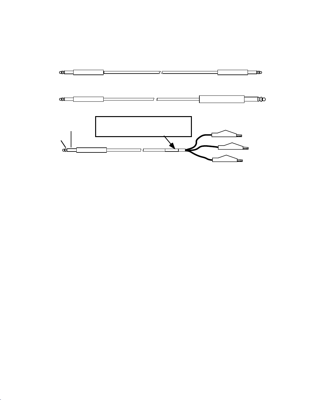
Figure 4. Cables for AM8e E&M Adapter Front Panel Connector ............................................8
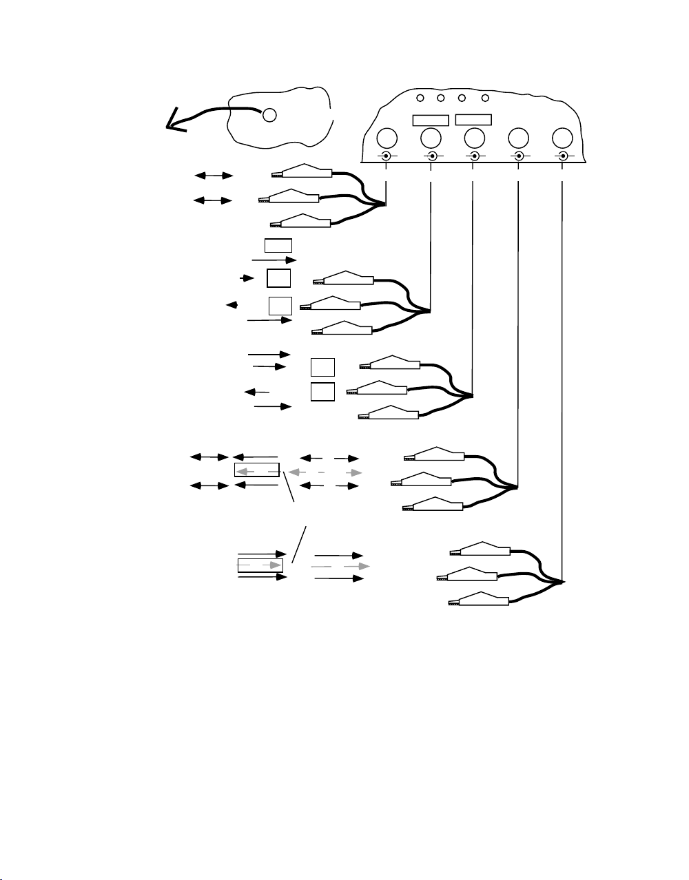
Figure 5. AM8e E&M Adapter Front Panel Connections......................................................10
Figure 6. Signaling Relationships ...................................................................................14
Figure 7. E&M Connection Diagrams ..............................................................................17
Figure 8. E&M Trunk Type Battery and Ground Connections (Type I and II)............................19
Figure 9. E&M Trunk Type Battery and Ground Connections (Type III, IV, and V) ....................21
Figure 10. Analog R2 Monitoring....................................................................................22
0044-TOC.C_196 October 18, 2000
v
Page 7

Table of Contents (18-0044) Model 300056 AM8e E&M Adapter
List of Tables
Table 1. E&M Lead Signaling Conventions.......................................................................19
October 18, 2000 0044-TOC.C_196vi
Page 8

Model 300056 AM8e E&M Adapter (18-0044) Instruction Manual
1. INTRODUCTION
This manual is intended for use with the Ameritec Model 300056 AM8e E&M
Adapter (P/N 300056). This manual should be used in conjunction with the AM8e
PCM/VF Call Analyzer Instruction Manual (P/N 180035), and the AM8e Protocol Table
Development Guide (P/N 180040).
This manual is divided into 4 major sections, as listed in the Table of Contents.
This first introductory section provides an overview of the AM8e VF Call Analyzer,
AM8e E&M Signaling Adapter, and Protocol Table Development Guide; all of which are
of fundamental importance to the instructions in this manual.
The second section describes the Model 300056 AM8e E&M Adapter, its front panel,
and connections.
The third section is an overview of the characteristics of the various E&M
connections and signaling types.
1.1 Ameritec AM8e PCM/VF Call Analyzer
The Ameritec AM8e PCM/VF Call Analyzer is a test set that is designed to emulate,
monitor, and analyze signaling activity at the PCM interface point on an
established connection.
Note: For brevity, the AM8e PCM/VF Call Analyzer will be referred to as the "Call
Analyzer" in the remainder of the text.
The Call Analyzer can emulate, or monitor and identify, activities at the near end
(Tx) or far end (Rx) of either of two 2.048 Mbps PCM spans. This unit is described
in the "Model AM8e PCM/VF Call Analyzer Instruction Manual" (P/N 180035).
Tests can be performed on any of 30 voice channels on the spans, and the Call
Analyzer may operate with any selection of one of eight signaling protocols.
Up to eight protocols may be loaded into the Call Analyzer, either from the factory
or by a user with an MS/DOS Compatible PC. The user may develop custom
protocols to conform to local standards, as described in the "AM8e Protocol Table
Development Guide".
0044-Text.C_ 203 October 18, 2000
1
Page 9

Instruction Manual (18-0044) Model 300056 AM8e E&M Adapter
Although the Call Analyzer can be used to test an analog loop circuit, it is not
specifically designed for direct connection to analog lines using E&M Signaling
conventions; therefore, Ameritec has developed the Model 300056 E&M Adapter.
1.2 AM8e Model 300056 E&M Adapter
The Model 300056 AM8e E&M Adapter is physically designed to replace the front
cover of the Call Analyzer. The illustration on the cover of this manual shows both
units as they would be set up for use.
Note: For brevity, the Model 300056 AM8e E&M Signaling Adapter will be referred
to as the "E&M Adapter".
The E&M Adapter is electrically connected to the Call Analyzer via a ribbon cable
from a "TO AM8e" connector on its front panel to the LINE/TIMS connector on the
rear panel of the Call Analyzer. All power and PCM2 input and output connections
between the E&M Adapter and the Call Analyzer are via this connector.
The interfaces between the E&M signaling and VF circuits are via bantam jacks on
the front panel of the E&M Adapter.
Functionally, the E&M Adapter is an Analog to Digital/Digital to Analog signal
converter, which converts an E&M Signal from its line or equipment interface at a
Central Office, to 2.048Mbps PCM Rx and Tx Signals, which are processed by the
Call Analyzer. This allows the Call Analyzer to Emulate or Monitor either the
near-end (Tx) or far-end (Rx) signaling on an E&M interface. The user must select
PCM2 as PCM input.
1.3 AM8e Protocol Table Development Guide and Disk
The AM8e Protocol Table Development Guide (P/N 180040) is a user's guide to
developing custom signaling protocols for the AM8e on an MS/DOS-compatible
Personal Computer. Also included with the Guide is a Development Disk, which
must be used together with third-party software as described in the Guide.
Custom protocols are required for E&M monitoring and emulation.
In many cases, Ameritec has developed protocols which may be supplied to the
user on a disk (or provided with the Call Analyzer). For example, "E&M_ADAPT"
(9220040-PP) will enable the Call Analyzer to be used with the E&M Adapter.
October 18, 2000 0044-Text.C_ 203
2
Page 10
Model 300056 AM8e E&M Adapter (18-0044) Instruction Manual
Other protocols are listed in an Addendum to the Guide (P/N 180126). For more
information, contact your local Ameritec Sales or Instruments Group
representative.
1.4 Overview of E&M Test Configuration
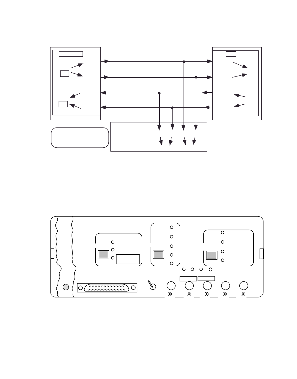
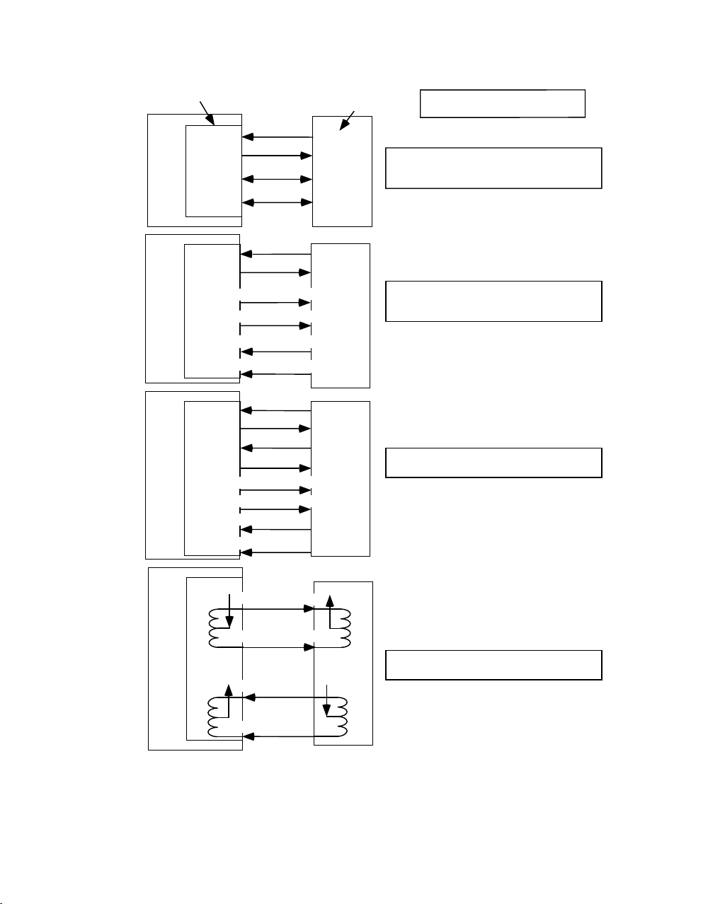
Figure 1 shows the interfaces between terminal signaling equipment and a
Central Office Switch trunk interface using 2-Wire E&M, 4-Wire E&M, or 4-Wire
2
E&M
connections. Figure 2 shows 4-Wire phantom E&M. The figures illustrate the
positions of the E&M Signaling Adapter to emulate or monitor the terminal or
switch. Both commonly-used circuit identifications "(T), (R), (T1), (R1), (E),
(M)" and E&M Adapter signal labeling on the front panel "A1, B1, A2, B2, E1, M1"
are shown in these illustrations.
BANTAM PLUG
BANTAM PLUG
sleeve
ring
tip
BANTAM PLUG
CABLE 48-0047, 6 FT.
CABLE 48-0048, 6 FT.
NOTE: Cables manufactured before 5/7/92 are
Green (Ring - r) and RED (Tip - t) and will not have
this color-code label
CABLE 48-0062, 6 FT.
Figure 1. 2- and 4-Wire E&M Connections
BANTAM PLUG
310 PLUG
RED (Ring)
GREEN (Tip)
BLACK (Sleeve)
0044-Text.C_ 203 October 18, 2000
3
Page 11
Instruction Manual (18-0044) Model 300056 AM8e E&M Adapter
r
Switch or E&M Call Analyzer Terminal or E&M Call Analyze
4W PHANTOM E&M OVERVIEW
EQUIPMENT mode
A1
(T)
(M)
M1
(R)
B1
(Trunk
Interface)
(T1)
A2
(E)
E1
(R1)
B2
NOTE: 4 Wire Phantom
connection is Trunk-type
V only.
internal
E1
Figure 2. 4-Wire Phantom E&M Connection
2. OPERATION OF THE E&M ADAPTER
2.1 Front Panel Controls and Indicators
Figure 3 shows the front panel of the E&M Adapter. The figure identifies the
sub-section number descriptions which follow.
LINE mode
A2B2(T1)
(M)
(R1)
A1
(T)
(R)
B1
A2 B2A1 B1
E&M Call Analyzer
M1
(E)
E1
Monitoring connections
M1
Model 300056
I
II
III
IV
V
(2.1.8)
E1M1M1E1E2M2M2
SB SG A2 B2Tx Rx A1 B1
(2.3.1) (2.3.2) (2.3.3) (2.3.4) (2.3.5)
Tx Rx
CONNECTION
(2.1.6)
(2.1.7)
E2
2W E&M
4W E&M
4W E&M
PHANTOM
4W
E&M
2
PWR
TYPE
(2.1.1)
ON
OFF
(2.1.5)
(2.1.4)
AM8e E & M Adapter
MODE
CO
GROUND
(2.3.6)
TO AM8e
(2.1.3)
(2.1.2)
EMULATE
LINE
MONITOR
EMULATE
EQUIPMENT
(2.2.1)
Figure 3. Model 300056 AM8e E&M Adapter Front Panel
October 18, 2000 0044-Text.C_ 203
4
Page 12

Model 300056 AM8e E&M Adapter (18-0044) Instruction Manual
2.1.1 PWR ON/OFF (Power ON/OFF Switch)
This switch allows the user to turn the power on and off.
Note: Power (+16V) is provided by the Call Analyzer, which must also be turned
ON. The cable between the Call Analyzer and the AM8e E&M Signaling
Adapter must also have been connected (refer to ¶2.2.1).
2.1.2 MODE (Mode Selector Switch)
This switch allows the user to emulate either a switch/trunk interface (equipment)
or a signaling circuit (line) location, or to monitor the connection between
locations.
The user may change the defined mode by pressing the mode switch to step to
the next mode until the desired mode is reached. Possible Modes indicated on
the panel are EMULATE LINE, MONITOR, and EMULATE EQUIPMENT.
2.1.3 MODE Indicators (Mode-Selected Indicators)
These indicators display the selected mode. As the user changes modes, the
indicators change. The illuminated LED indicates the current mode of operation.
2.1.4 TYPE (E&M Type-Select Switch)
This switch allows the user to select the E&M type that is active. Each press of
the switch selects, in rotation, the 5 common E&M types. For further description
of each of the E&M types, refer to Section 3.
2.1.5 TYPE Indicators (E&M Type Indicators)
These LED's indicate which of the five common E&M types (I, II, III, IV, or V) has
been selected.
0044-Text.C_ 203 October 18, 2000
5
Page 13

Instruction Manual (18-0044) Model 300056 AM8e E&M Adapter
2.1.6 CONNECTION (Connection-Type Switch)
This switch allows the user to select between E&M Connection Types. Each press
of the switch selects, in rotation, the four common line connection types. For
further description of the E&M connections, refer to Section 3. The types selected
are:
2 Wire E&M See ¶3.1.1
4 Wire E&M See ¶3.1.2
4 Wire E&M
4 Wire Phantom E&M See ¶3.1.4
2
See ¶3.1.3
2.1.7 CONNECTION Indicators (Connection-Type Indicators)
These LED's indicate to the user the connection type that has been selected.
2.1.8 E1/M1, and E2/M2 Indicators (Active Status of E&M Signals)
These LED's display the status of the E&M signaling leads on the Tx and Rx jacks
below them. When lighted, they indicate that the signal is present.
Note: When EMULATE EQUIPMENT is selected, the functions of the jacks and
indicators are reversed. This is signified within the rectangular marking
surrounding (MODE:) "EMULATE EQUIPMENT", "M1 E1", and "M2 E2" on
the front panel.
2.2 Connection to the Call Analyzer
2.2.1 TO AM8e (AM8e Interface Connection)
This is a DB-25 male connector, shown in Figure 3, where the 25-pin female
connector of Cable 48015600 (supplied with the unit) is connected.
The other end of this cable has a 24-pin ribbon connector which connects to the
LINE/TIMS connector on the rear panel of the Call Analyzer.
October 18, 2000 0044-Text.C_ 203
6
Page 14
Model 300056 AM8e E&M Adapter (18-0044) Instruction Manual
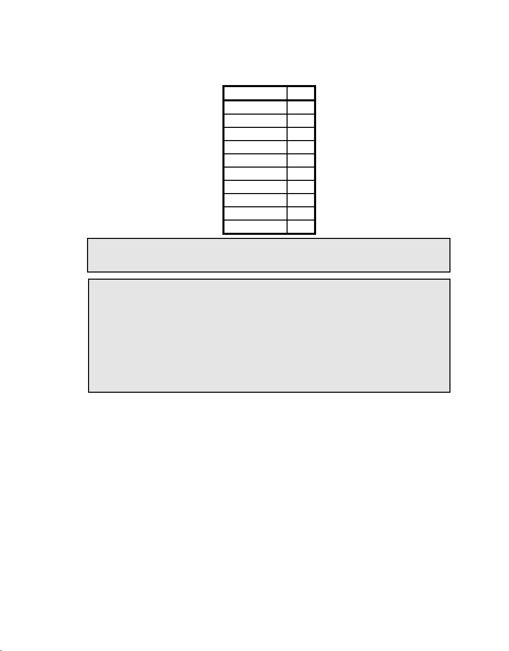
The signals provided from the Call Analyzer are as shown below:
SIGNAL PIN
LID-R 9
LID-T 10
LID-R1 11
LID-T1 12
CO GROUND 15
CO GROUND 16
CO GROUND 21
CO GROUND 22
+16 volt power 23
+16 volt power 24
CAUTION: Power should be turned OFF on the AM8e before making this
connection.
CAUTION: When using the LINE/TIMS jack as a connection point from the Call
Analyzer to the CO for LOOP or PCM signals (when not using the E&M
Adapter); BE SURE THAT PINS 23 and 24 are NOT connected to CO
ground.
(These connections were not provided in early Call Analyzers, which
show pins 9-11 as unused, and pins 23 and 24 as extra CO
GROUNDS).
2.3 Connections to Test Leads
Connections for the E&M signaling, ground, battery, and VF interfaces may be
made with any of the three types of cables which have a bantam connection on
one end and a bantam plug, type 310 plug, or clip leads on the other. Figure 4
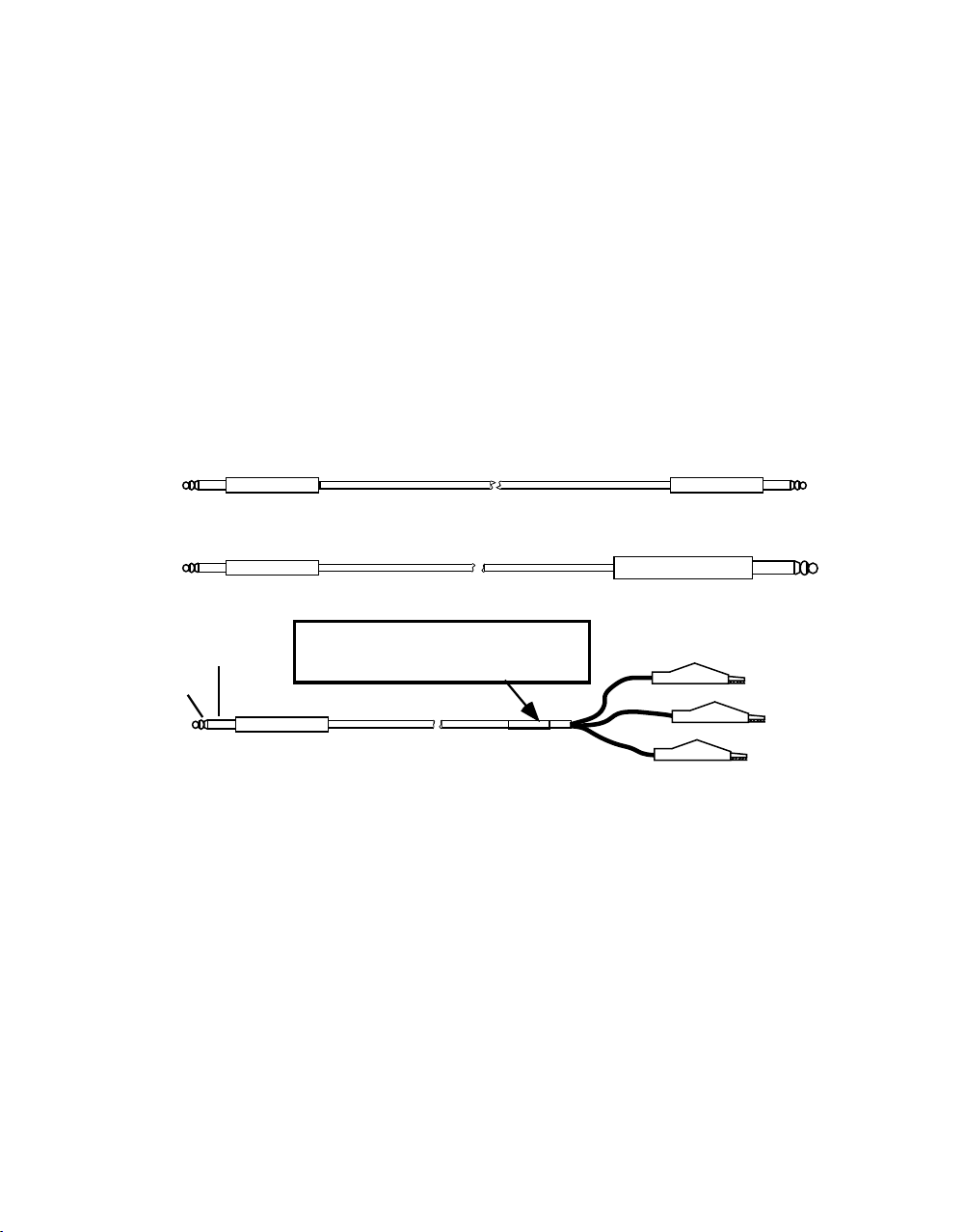
shows these cables. An additional single conductor is required to connect the
CO GROUND.
Figure 4 is a detailed illustration of the jacks on the E&M Signaling Adapter. The
figure further shows the E&M, VF, SG, and SB leads as if cables with clip leads
were connected to the jacks.
0044-Text.C_ 203 October 18, 2000
7
Page 15
Instruction Manual (18-0044) Model 300056 AM8e E&M Adapter
Signaling leads are identified as they would appear on the clip leads when the
appropriate MODE, TYPE, and CONNECTION are selected. Further information on
the jacks is provided in the subsections which follow.
BANTAM PLUG
BANTAM PLUG
NOTE: Cables manufactured before 5/7/92 are
sleeve
ring
tip
BANTAM PLUG
Green (Ring - r) and RED (Tip - t) and will not have
this color-code label
Figure 4. Cables for AM8e E&M Adapter Front Panel Connector
2.3.1 SB/SG Connection
This is a bantam jack for connection to the line Signal Battery (SB) and Signal
Ground (SG). SB is on the tip conductor; SG is on the ring conductor. CO
Ground is on the sleeve conductor. This connection is used only for E&M trunk
types II, III, and IV.
2.3.2 Tx/Rx for E1/M1
This is a bantam jack for connection to the E1 and M1 leads. The status of these
signaling leads is indicated by the E1 and M1 indicators directly above the
connection. For MODE MONITORING and EMULATE LINE, E1 is on the tip
conductor, and M1 is on the ring conductor. When the unit is set to MODE,
EMULATE EQUIPMENT, the connections are reversed. These leads are used for all
connection and trunk types except 4W Phantom E&M.
CABLE 48-0047, 6 FT.
CABLE 48-0048, 6 FT.
CABLE 48-0062, 6 FT.
BANTAM PLUG
310 PLUG
RED (Ring)
GREEN (Tip)
BLACK (Sleeve)
October 18, 2000 0044-Text.C_ 203
8
Page 16

Model 300056 AM8e E&M Adapter (18-0044) Instruction Manual
2.3.3 Tx/Rx for E2/M2
This is a bantam jack for connection to the E2 and M2 leads. These leads are used
only for 4 Wire E&M
above). The status of these signaling leads (when used) is indicated by the E2
and M2 indicators directly above the connection. For MODE, MONITORING and
EMULATE LINE, E2 is on the tip conductor, and M2 is on the ring conductor.
When the unit is set to MODE, EMULATE EQUIPMENT, the connections are
reversed.
2
connection type (in addition to the E1 M1 leads, described
2.3.4 A1/B1 VF Connector
This is a bantam jack connection for the 4W Transmit or 2W Transmit/Receive VF
leads. The tip (or A1) is on the tip conductor; the ring (or B1) is on the ring
conductor.
Note: In EMULATE LINE or EQUIPMENT, signal flow is out of the E&M Adapter.
When in MONITOR mode, this jack must be connected to the A1 and B1
(transmit) leads from the terminal (line).
2.3.5 A2/B2 VF Connector
This is a bantam jack connection to the Receive VF leads. These leads are used
(in addition to the A1 B1 leads) with 4 Wire E&M, 4W E&M
connections.
Note: In EMULATE LINE or EQUIPMENT signal flow is into the E&M Adapter.
When in MONITOR mode, this jack must be connected to the A2 and B2
(receive) leads to the terminal (line).
2
, and 4W Phantom E&M
2.3.6 CO Ground Terminal
This is a yellow binding post located at the left end of the Adapter. It should be
used to connect the Central Office ground to the adapter. (A similar binding post
on the back of the AM8e VF/PCM Call Analyzer may also be used.) The binding
post is recessed so that there will be no interference when the Adapter is secured
to the front of the AM8e VF/PCM Call Analyzer for carrying or storage.
0044-Text.C_ 203 October 18, 2000
9
Page 17
Instruction Manual (18-0044) Model 300056 AM8e E&M Adapter
Used for
E&M Types
II, III, IV
Used for E&M Types
I, II, III, IV, V (except
4W Phantom E&M
connection
Used only for 4W E&M
connection
HDX VF for
2W E & M
FDX VF for 4W E&M
CO Ground
Yellow Binding Post
RED (Ring)
SG
SB
CO Ground
MONITOR M1
(Rx)
MONITOR E1
MONITOR M2
2
MONITOR E2
for 4W E & M
Derived E&M Leads for 4W Phantom
E&M connection (E&M Type I or V)
(Tx)
(Rx)
FDX VF
BLACK (Sleeve)
M1 E1
E1 M1
(Tx)
E
(2.3.6)
GREEN (Tip)
boxed items are for
EMULATE EQUIPMENT
RED (Ring)
GREEN (Tip)
n. c.
M2 E2
E2 M2
n. c.
EMULATE
LINE // MONITOR
//
E
E M
//
//
EMULATE
LINE & MONITOR
M
(2.3.1)
RED (Ring)
B1 (R)
A1 (T)
E1M1M1E1E2M2M2
Tx RxSB SG A2 B2Tx Rx A1 B1
(2.3.2)
GREEN (Tip)
RED (Ring)
GREEN (Tip)
n. c.
B2 (R1)
A2 (T1)
n. c.
(2.1.8)
E2
(2.3.3) (2.3.4) (2.3.5)
RED (Ring)
GREEN (Tip)
Figure 5. AM8e E&M Adapter Front Panel Connections
2.4 Setting the Operating Conditions
Both the Call Analyzer and E&M Adapter must be configured correctly for the mode,
and an appropriate protocol must be selected in the Call Analyzer. This protocol
must be designed for translating the incoming PCM signal from the E&M Adapter
into Call Analyzer events or for translating the Call Analyzer events into a PCM
signal that the E&M Adapter will convert into E, M, and VF signals.
October 18, 2000 0044-Text.C_ 203
10
Page 18
Model 300056 AM8e E&M Adapter (18-0044) Instruction Manual
The basic steps for setting up, connecting, and using the E&M Adapter follow:
1. Remove the Signaling Adapter from the front of the Call Analyzer by
opening the holding clips on either side, and set it on top of or beside the
PCM/VF Call Analyzer.
2. After verifying that the Call Analyzer is turned OFF, connect the 48015600
Ribbon Cable (supplied) between the "TO AM8e" connector on the
Signaling Adapter and the LINE/TIMS connector on the PCM/VF Call
Analyzer.
3. Make the appropriate connections for the E&M test configuration. Refer
to Figures 1, and 4 - 7 and accompanying descriptive text. For
emulation, disconnect through-connections (if not done by test jacks at
the CO). For monitoring, leave the connections in place.
4. Turn ON the Call Analyzer and the E&M Adapter, and verify that the PWR
indicator on the E&M Adapter is lighted.
5. Set both units to match. (The E&M Adapter may be set directly through the
front panel MODE, TYPE, and CONNECTION switches, previously
described, or remotely through AM8e commands as described in
sub-section 2.5.)
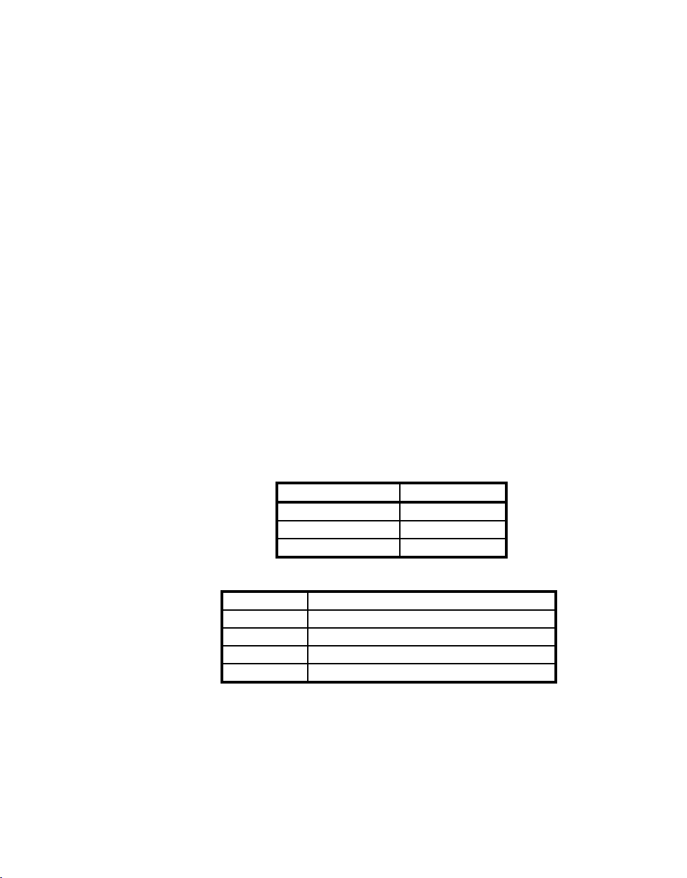
E&M ADAPTER CALL ANALYZER
EMULATE LINE MODE - emulate
EMULATE EQUIPMENT MODE - emulate
MONITOR MODE - monitor
6. Also set the following Call Analyzer parameters:
IMITATE te/line or switch (not significant for PCM operations)
ANALOG/PCM pcm int clk
PROTOCOL For the E&M requirements at the test location
INPUT PCM2
Channel 1
7. Set the correct TYPE of E&M for the equipment under test.
8. Set the correct CONNECTION type for the equipment under test.
9. To set up other parameters and perform tests, follow the procedures in
the Model AM8e PCM/VF Call Analyzer Instruction Manual (18-0035).
0044-Text.C_ 203 October 18, 2000
11
Page 19

Instruction Manual (18-0044) Model 300056 AM8e E&M Adapter
Note: The E&M Protocol may automatically set the Call Analyzer parameters. If
you have any further questions in setting up the test configuration,
applications help is available from 8 AM to 5 PM Pacific Time by
contacting Customer Service at the address or phone numbers on the title
sheet of this manual.
2.5 Remote Control of E&M Adapter
The E&M Adapter may be set directly through the use of the front panel MODE,
TYPE, and CONNECTION switches, or remotely through a terminal connected to
the Call Analyzer's RS232 port. A command is used for setting each switch, and
another command is used to read the conditions that have been set up.
2.5.1 Remote Setup (ADP Command)
Each E&M Adapter switch can be set remotely through the use of the following
command:
(ADP=xyz) x must be 1 for E&M Adapter
y = switch
z= switch selection as shown below
if y then z
0 = MODE 0 = EMULATE LINE
1 = TYPE 0 = I
2 = CONNECTION 0 = 2W E&M
1 = MONITOR
2 = EMULATE EQUIPMENT
1 = II
2 = III
3 = IV
4 = V
1 = 4W E&M
2 = 4W E&M
3 = 4W PHANTOM E&M
2
As an example, three commands would be required to place the E&M Adapter into
monitor mode for a type III, 4 wire E&M connection:
(ADP=101) (ADP=112) (ADP=121)
October 18, 2000 0044-Text.C_ 203
12
Page 20

Model 300056 AM8e E&M Adapter (18-0044) Instruction Manual
2.5.2 Remote Status (RADP Command)
The settings of the E&M Adapter switches can be read remotely through the use of
the following command and response:
command response
(RADP) ADAPTER STATUS = m t c (as shown below)
m = MODE t = TYPE c = CONNECTION
0 = EMULATE LINE
1 = MONITOR
2 = EMULATE EQUIPMENT
0 = I
1 = II
2 = III
3 = IV
4 = V
0 = 2W E&M
1 = 4W E&M
2 = 4W E&M
3 = 4W PHANTOM E&M
2
As an example, the status for the monitor mode, type III, 4 wire E&M connection:
(RADP) ADAPTER STATUS=121
2.6 Call Analyzer Display and Bit Indicators
When the E&M Adapter and Call Analyzer are processing calls, both the display and
the bit indicators (LEDs) on the Call Analyzer front panel provide call information.
The display and bit indicators may be read locally or by remote control, as
desired. Refer to the AM8e PCM/VF Call Analyzer Instruction Manual for information
on the front panel and Remote Control.
Events and details are displayed on the Call Analyzer in accordance with the
protocol that is used.
The "Tx" and "Rx", "a" and "b" bit indicators on the Call Analyzer monitor the
states of the E&M type indicators (refer to 2.1.5). The "c" and "d" indicators are
always set to 1 (ON).
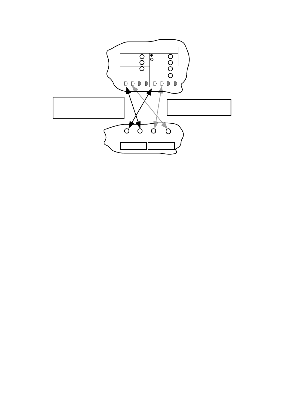
The following diagram shows the relation between the E and M signals as
displayed on the front panel of the E&M Adapter, the "a" and "b" indicators on the
Call Analyzer front panel, and the open or closed states of the signaling relays
(described in sub-section 3.2 and shown in Figure 8).
0044-Text.C_ 203 October 18, 2000
13
Page 21
Instruction Manual (18-0044) Model 300056 AM8e E&M Adapter
TRUNK STATUS
OFFHOOK
EMULATE EMULATE
OFFHOOK
FAR
abcd
A+B-
T
RING
E
R
OFFHOOK
X
NEAR
EMULATE
abcd
Bit indicator is ON (1) for
signaling circuit relay
closed. OFF (0) for relay open.
M1
E1
M1
E2M2M2
E1
Figure 6. Signaling Relationships
When monitoring the Rx and Tx indications with a remote terminal, the E&M
protocol will normally use channel 1. All other channels will be inactive.
3. E&M SIGNALING DESCRIPTION
E&M Signaling is a type of DC signaling interface between switching equipment
and transmission equipment. It is used in conjunction with VF signaling lines
(A1, B1, A2, and B2) and, for some E&M types, ground and battery lines.
S
W
T
X
Call Analyzer Front Panel
Rx and Tx bit displays
c and d indicators are always ON (1)
The b indicator is only valid
for 4W E&M connection
2
E&M Analyzer E and M lead Indicators.
Lighted = ON (1) at Call Analyzer
E2
By changing the voltage level or ground/open circuit conditions on the E&M
leads, (depending on type) information may be transferred between the switching
equipment and the transmission equipment; such as seizure of circuit, seize
acknowledgement, circuit release, dial pulsed digits, etc.
The way in which signals are applied to the leads allows each lead to have the
same name on both ends of the physical connection between the switching
equipment and the line, and permits a tip-tip and ring-ring patching
configuration.
October 18, 2000 0044-Text.C_ 203
14
Page 22

Model 300056 AM8e E&M Adapter (18-0044) Instruction Manual
The E&M Adapter follows these conventions:
• From the switching equipment point of view, the "M" lead typically
transmits either a ground or battery condition to the transmission
equipment, while the "E" lead typically receives either open or ground
signals from the transmission equipment.
Therefore, the front panel of the AM8e E&M Adapter is marked to show
this signal direction for the E and M leads for LINE or EQUIPMENT
emulation. (MONITOR is the same as LINE).
• From the transmission equipment point of view, the "M" lead typically
receives either open or ground signals from the line equipment, while the
"E" lead typically transmits either a ground or battery condition to the
switching equipment. A second set of markings on the front panel shows
these signal directions.
• When the unit is monitoring "E" is assumed to be a signaling output, and
M is assumed to be a signaling input.
3.1 Connection Types
The E&M Adapter provides for the four basic E&M connection types. These are
illustrated in Figure 7. (Figure 1 also illustrates the connection of an E&M Adapter
and Call Analyzer).
• 2-wire E&M: E1, M1, A1 (tip), B1 (ring)
• 4-wire E&M: E1, M1, A1 (tip), B1 (ring), A2 (tip1), B2 (tip2)
2
• 4-wire E&M
: E1, M1, E2, M2, A1 (tip), B1 (ring), A2 (tip1), B2 (ring 2)
• 4-wire E&M Phantom: A1, B1, A2, B2. (E-lead signals are carried via the A1
B1 lines, while M-lead signals are carried via the A2 B2 lines.
• In addition to the VF and DC signaling lines, SB (signal battery) and SG
(signal ground) leads are used in E&M types II through IV to supply battery
and ground signal levels between the signaling ends. (Refer to
sub-section 3.2 for the ways in which these leads are used).
0044-Text.C_ 203 October 18, 2000
15
Page 23

Instruction Manual (18-0044) Model 300056 AM8e E&M Adapter
3.1.1 2-wire E&M
A1 and B1 are bi-directional (half-duplex), acting as both send and receive for VF
signals including voice, DTMF signaling, and MF signaling. The E and M leads
send and receive DC signaling voltages in accordance with the E&M type. SB and
SG leads are used in types II through IV.
3.1.2 4-wire E&M
A1 and B1 are uni-directional, handling only VF send signals. A2 and B2 are also
uni-directional, handling only VF receive signals (a full-duplex configuration).
The E&M leads send and receive signaling voltages in accordance with the E&M
type. SB and SG leads are used in types II through IV.
3.1.3 4-wire E&M
A1 and B1 and A2 and B2 are also full duplex for VF signaling. There are two sets
of E&M leads which allow DC signaling from both ends simultaneously. This is a
Type V interface which does not require SB or SG leads.
2
3.1.4 Phantom E&M
A1 and B1 and A2 and B2 are full duplex for VF signaling. Physical E&M
connections are not required because the circuit ends are terminated by center
tapped transformers. This configuration is also sometimes called a "derived
circuit". The connection to E and M circuits is made via transformer center taps
within the equipment (and the E&M Analyzer). Phantom E&M can only be used
with a type V connection, because there is no way to transport the SB and SG
leads through the derived circuit.
• When in emulate line mode, the E signal is sent via the A1 and B1 leads,
while the M signal is received via the A2 and B2 leads.
• When in emulate equipment mode, the M signal is sent via the A1 and B1
leads, while the E signal is received via the A2 and B2 leads.
• When in monitor mode, the E signal can be monitored via the A1 and B1
leads, and the M signal can be monitored via the A2 and B2 leads.
October 18, 2000 0044-Text.C_ 203
16
Page 24
Model 300056 AM8e E&M Adapter (18-0044) Instruction Manual
EMULATE
EQUIPMENT
Switch
Switch
Switch
Trunk
Circuit
Trunk
Circuit
Trunk
Circuit
(Rx)
(Tx)
T (A1)
R (B1)
T1 (A2)
R1 (B2)
T (A1)
R (B1)
T1 (A2)
R1 (B2)
CONNECTION
2W E&M
E1
M1
T (A1)
R (B1)
4W E&M
E1
M1
T1 (A2)
R1 (B2)
T (A1)
R (B1)
4W E&M
E1
M1
E2
M2
T1 (A2)
R1 (B2)
T (A1)
R (B1)
2
EMULATE
LINE or MONITOR
(Tx)
(Rx)
Signaling
Circuit
Signaling
Circuit
Signaling
Circuit
MODE: Setting on E&M Adapter if it is
substituted for (or monitors) the circuit.
TYPE I and V shown. Refer to Figure 8 for ground
and battery application to E & M lines and for use
of SB and SG leads for TYPEs II, III, and IV.
TYPE I and V shown. Refer to Figure 8 for ground
and battery application to E & M lines and for use
of SB and SG leads for TYPEs II, III, and IV.
TYPE V only. Refer to Figure 8 for application of
Ground and Battery to E & M leads.
E
T (A1)
R (B1)
T1 (A2)
R1 (B2)
4W PHANTOM
E&M
T1 (A2)
R1 (B2)
T (A1)
R (B1)
MM
Signaling
Circuit
E
TYPE I or V only. Refer to Figure 8 for application of
Ground and Battery to E & M leads.
Switch
Trunk
Circuit
Figure 7. E&M Connection Diagrams
0044-Text.C_ 203 October 18, 2000
17
Page 25

Instruction Manual (18-0044) Model 300056 AM8e E&M Adapter
3.2 E&M Trunk Types
There are five different types of E&M trunk signaling methods (identified by
Roman numerals I, II, III, IV, and V) which are in common use. The types differ
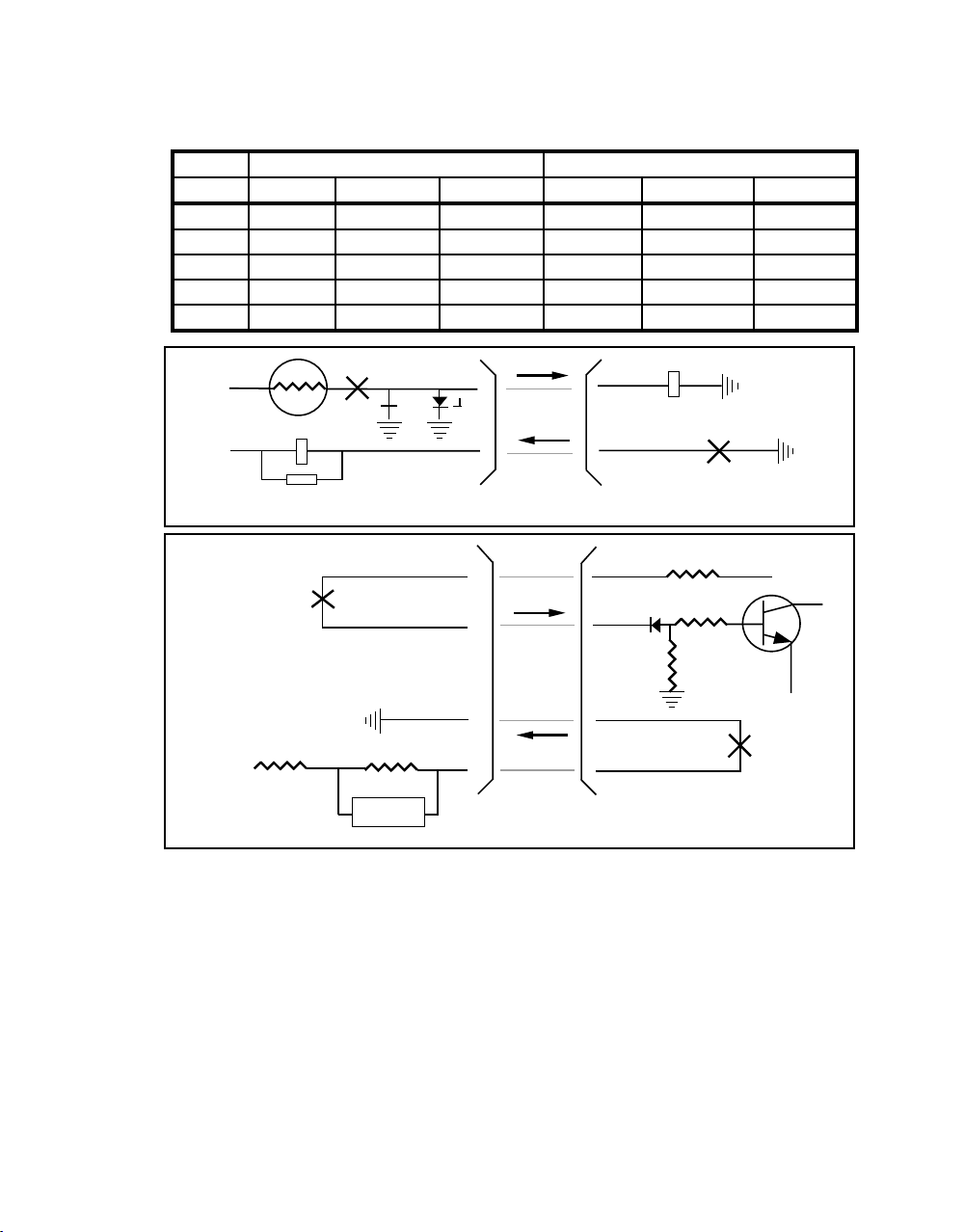
mainly in the way Battery and Ground are supplied to the E&M leads. Table 1
summarizes these differences for ON HOOK and OFF HOOK conditions. Figure 8
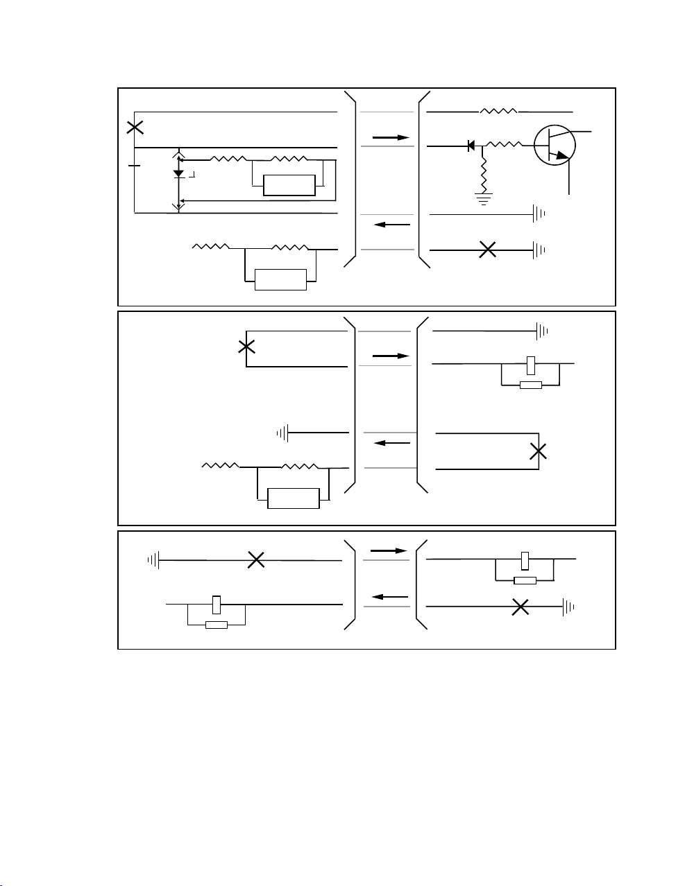
shows simplified schematic diagrams for each type. Sub-sections 3.2.1 through
3.2.5 describe each type.
3.2.1 E&M TYPE I
The Type I interface is the original E&M Interface. Signaling on the M lead is from
the trunk equipment to the transmission equipment.
• Battery is supplied for Off-Hook condition.
• Ground is supplied for On-Hook condition
• The E lead is used for signaling from the transmission equipment to the
trunk equipment.
• Local transmission equipment facility ground is used for Off-Hook,
• Open circuit is used for On-Hook.
3.2.2 E&M TYPE II
The Type II interface (as well as Types III and IV) makes use of two additional
leads, SB (Signal Battery) and SG (Signal Ground).
In the Type II interface, battery voltage is supplied to the trunk equipment by the
signaling equipment on the SB lead.
The Trunk equipment signals the signaling equipment by opening and closing a
connection between SB and the M lead.
The effect is that the trunk equipment signals the signaling equipment with
battery for Off-Hook and open for On-Hook.
Signaling from the signaling equipment to the trunk equipment is accomplished
by opening and closing a connection between the E lead and ground.
The effect is to signal from the signaling equipment to the trunk equipment with
open for On-Hook and ground for Off-Hook.
October 18, 2000 0044-Text.C_ 203
18
Page 26
Model 300056 AM8e E&M Adapter (18-0044) Instruction Manual
Table 1. E&M Lead Signaling Conventions
TRUNK TO SIGNALING CIRCUIT SIGNALING TO TRUNK CIRCUIT
TYPE LEAD ON-HOOK OFF-HOOK LEAD ON-HOOK OFF-HOOK
I M Ground Battery E Open Ground
II M Open Battery E Open Ground
III M Ground Battery E Open Ground
IV M Open Ground E Open Ground
V M Open Ground E Open Ground
– 48 V
– 48 V
TYPE I
– 48 V
TYPE II
R
E
Trunk Circuit
P
Figure 8. E&M Trunk Type Battery and Ground Connections (Type I and II)
3.2.3 E&M TYPE III
P
SENSOR
Trunk Circuit
SB
SG
M
E
M
E
M
E
SB
M
SG
E
Signaling Circuit
M
R
Signaling Circuit
– 48 V
– 24 V
R
The Type III interface is essentially the same as the Type I interface in that
signaling on the M lead is with battery for Off-Hook and ground for On-Hook.
The difference between Types I and III is that with Type III signaling, Battery and
Ground used for signaling on the M lead are supplied to the trunk equipment on
the SB and SG leads, respectively.
0044-Text.C_ 203 October 18, 2000
19
Page 27

Instruction Manual (18-0044) Model 300056 AM8e E&M Adapter
3.2.4 E&M TYPE IV
The signaling used with the Type IV interface is essentially the same as the Type II
interface. The difference is in that with Type IV signaling the SB lead is grounded
in the signaling equipment, and battery is supplied to the M lead.
The trunk circuit provides a path for the battery to ground by closing the contacts
between M and SB. The effect is to signal with open for On-Hook and ground for
Off-Hook.
The E lead is used to signal from the signaling equipment to the trunk equipment
by closing contacts between E and SG in the signaling equipment. The effect is
to signal using open for On-Hook and ground for Off-Hook.
3.2.5 E&M TYPE V
Type V is not used in the North American Network, but is the most common E&M
Type outside of North America. Like the Type I interface, the Type V interface
does not use the SB and SG leads.
The difference from Type I is that with Type V signaling battery is supplied to the
M lead on the signaling equipment side instead of the trunk equipment side.
The trunk equipment signals to the signaling equipment by closing contacts to
local ground, thereby providing a path for the battery to ground on the M lead.
The effect is to signal using open for On-Hook and ground for Off-Hook.
The trunk circuit provides battery to the E lead. Signaling on the E lead is from
the signaling equipment to the trunk equipment by closing contacts from the
signaling equipment E lead to local ground. The effect is to signal using open for
On-Hook and ground for Off-Hook.
October 18, 2000 0044-Text.C_ 203
20
Page 28
Model 300056 AM8e E&M Adapter (18-0044) Instruction Manual
P
TYPE III
TYPE IV
– 48 V
– 48 V
950
P
38
SENSOR
SENSOR
Trunk Circuit
SENSOR
Trunk Circuit
SB
SG
SB
M
E
M
SG
E
R
– 48 V
– 24 V
Signaling Circuit
SB
M
SG
E
SB
M
M
– 48 V
SG
E
E
Signaling Circuit
M
– 48 V
P
– 48 V
TYPE V
E
Trunk Circuit
P
M
E
M
E
Signaling Circuit
Figure 9. E&M Trunk Type Battery and Ground Connections (Type III, IV, and V)
0044-Text.C_ 203 October 18, 2000
21
Page 29
Instruction Manual (18-0044) Model 300056 AM8e E&M Adapter
APPENDIX A
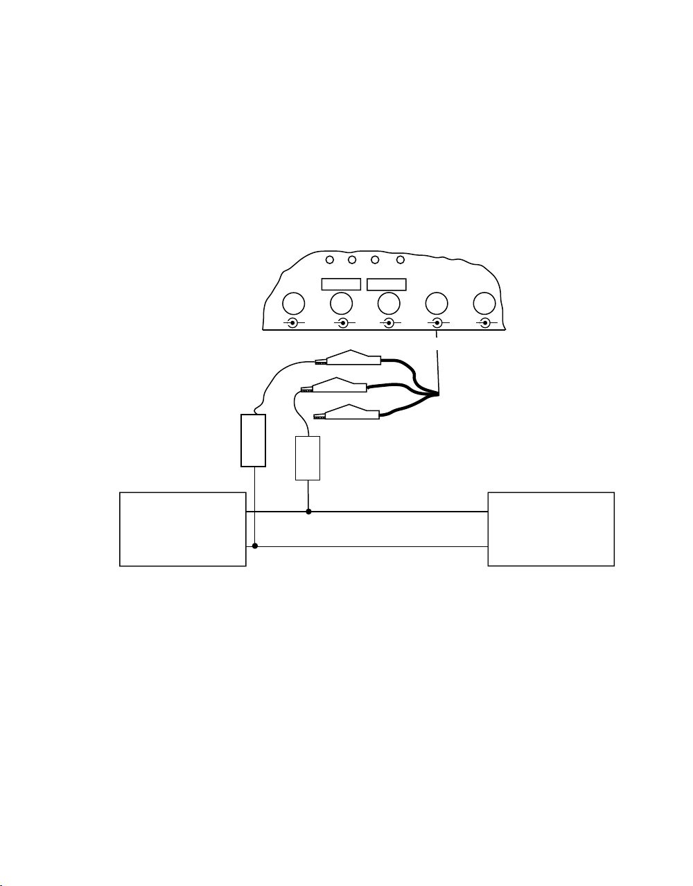
A.1 Analog R2 Monitoring in AM8e
The user can monitor the R2 digit in 2-wire (loop) Analog circuits by connecting
the analog circuit to the A1 B1 leads of the E&M Adapter. None of the other leads
are used in this configuration.
A diagram of the configuration is shown in Figure 10.
E&M Adapter
A
Analog R2
Terminal end
B
Blocking Capacitors
C1 and C2
can be 100 µF
200 V or higher
Analog R2
Switch end
E1M1M1E1E2M2M2
Tx RxSB SG A2 B2Tx Rx A1 B1
RED (Ring)
GREEN (Tip)
C2
A
B
BLACK (Sleeve)
C1
E2
(2.3.4)
480062 cable (or equivalent)
Figure 10. Analog R2 Monitoring
Set switches on the E&M Adapter as follows:
MODE: MONITOR TYPE: V CONNECTION: 2W E&M
Set the Call Analyzer as described in ¶2.4. Protocol selected must have been
designed for Analog R2 Monitoring.
October 18, 2000 0044-Text.C_ 203
22
Page 30

Ameritec is dedicated to serving the worldwide
telecommunications community by providing
competitively priced, state-of-the-art test equipment
that is supported by the finest in marketing,
engineering development and customer service.
760 Arrow Grand Circle
Covina, CA 91722 USA
TEL 626.915.5441
FAX 626.915.7181
www.ameritec.com
 Loading...