


Document No. ICA-451
OPERATIONS AND INSTRUCTIONS FOR CONTINUED AIRWORTHINESS (ICA) MANUAL
FOR
MODEL AK-451-( ) Series
406 MHz ELT Emergency Locator Transmitter with GPS/NAV position
AMERI - KING CORPORATION
17881 Sampson Lane
Huntington Beach, CA 92648
Tel: (714) 842-8555
Fax: (714) 842-4235
PREPARED BY |
AMERI-KING CORP. |
|
PAGE |
|
Q. Phan |
|
NO. |
||
DATE: 10-22-08 |
SUBJECT |
|
|
2 |
|
|
|
|
|
CHECKED BY |
OPERATIONS AND |
|
REPORT |
REV NO. |
INSTRUCTIONS FOR |
|
|||
K. Van |
CONTINUED |
|
NO. |
|
DATE: 10-22-08 |
|
IM-451 |
NC-1 |
|
AIRWORTHINESS (ICA) |
|
|||
|
|
|
|
|
|
MANUAL |
|
|
|
PREPARED BY: _______________________________________ DATE: 4/4/07
Quang Phan, Senior Design Engineer
APPROVED BY: _______________________________________ DATE: 4/8/07
Keith Van, Engineering Manager
APPROVED BY: _______________________________________ DATE: 4/10/07
Victor Vu, General Manager
REVISION TABLE
|
REVISION |
DESCRIPTION |
CHANGED |
APPROVED |
DATE |
|
|
BY |
BY |
|
|||
|
|
|
|
|
||
|
NC |
First Release |
Q.P. |
K. V. |
10-22- |
|
|
|
|
|
|
2008 |
|
|
NC-1 |
Add Periodic |
|
|
|
|
|
|
Maintenance Check List |
Q.P. |
K.V. |
10-24- |
|
|
|
with Compliance Cross |
|
|
08 |
|
|
|
References |
|
|
|
|
|
|
|
|
|
|
|
|
|
|
|
|
|
|
|
|
|
|
|
|
|
|
|
|
|
|
|
|
|
|
|
|
|
|
|
|
|
|
|
|
|
|
|
|
|
|
|
|
|
|
|
|
|
|
|
|
|
|
|
|
|
|
|
|
|
|
|
|
|
|
2

DOCUMENT NO.: IM-451 REV. NC
APPLICABILITY
Model/Part |
Fixed Whip |
Or Fixed Rod |
Or Fixed |
Portable Whip |
No.: |
Antenna |
Antenna |
Blade Antenna |
Antenna |
|
451017-1B |
451017-2A |
451017-3A |
451017-4S |
|
406/121.5 |
406/121.5/243 |
406/121.5/243 |
406/121.5/243 |
|
MHz |
MHz |
MHz |
MHz |
|
|
|
|
|
AK451- |
S |
S |
S |
- |
(AF) |
S |
S |
S |
M |
AK451- |
- |
- |
- |
M |
(AF)(AP) |
- |
- |
- |
M |
AK - 451- |
|
|
|
|
(AP) |
|
|
|
|
AK - 451-(S) |
|
|
|
|
M: Mandatory. The respective model must be accompanied by this antenna. S: Selective. The respective model must be accompanied by at least 1 of these antennas.
- : Not applicable
4500010-1: Battery Package, Lithium, LiMnO2, 90 Hrs Lasting.
TS-451: Computer Test Set and ELT Coding Equipment for AK-451
|
|
TABLE OF CONTENTS |
|
Table of Contents............................................................................................ |
4 |
||
List of Figures................................................................................................. |
|
6 |
|
|
|
SECTION I |
|
|
|
GENERAL INFORMATION & |
|
|
|
BATTERY REPLACEMENT INSTRUCTIONS |
|
1.1 |
Scope |
............................................................................................ |
7 |
1.2 |
Overview .......................................................................................... |
7 |
|
|
1.2.1 |
Application and Equipment Limitation.............................. |
7 |
|
1.2.2 |
Certification ....................................................................... |
8 |
1.3 |
Technical Characteristics.................................................................. |
8 |
|
1.4 |
Battery replacement instructions ...................................................... |
13 |
|
|
1.4.1 |
ELT main unit battery replacement instructions ................ |
13 |
|
1.4.2 |
ELT remote unit battery replacement instructions ............. |
15 |
|
|
SECTION II |
|
|
|
OPERATIONS |
|
2.1 |
General |
........................................................................................ |
16 |
2.2 |
Operation ........................................................................................ |
17 |
|
2.3 |
Transmitter Functional Test ................................................................. |
17 |
|
|
2.3.1 |
Main Switch ON/OFF/ARM Operation................................. |
18 |
|
2.3.2 |
Transmitter ID Programming and Self-Test .......................... |
18 |
|
2.3.3 |
System Integration Test ......................................................... |
19 |
|
2.3.4 |
Green ON Lights and Buzzer Sound Functions..................... |
22 |
|
2.3.5 |
Transmitter Functional Test for ELT-(S) only....................... |
22 |
SECTION III
INSTRUCTIONS FOR CONTINUED AIRWORTHINESS (ICA)
3.1 |
Periodic Maintenance (Instructions for Continued Airworthiness).... |
26 |
|
|
3.1.1 |
Secure Inspection................................................................... |
26 |
|
3.1.2 |
Corrosion Inspection for Coaxial Cable................................. |
26 |
3 |
4 |
3.1.3 |
Corrosion Inspection for Remote Wiring Modular Cable |
......26 |
3.1.4 |
Expiration Date Check............................................................ |
26 |
3.1.5 |
Battery Leakage Check........................................................... |
26 |
3.1.6 |
Operational Test ..................................................................... |
26 |
3.1.7.1 |
G-Switch Check...................................................................... |
26 |
3.1.7.2 |
Antenna Check ....................................................................... |
27 |
3.1.8 |
Verification of Digital Message.............................................. |
27 |
3.1.9 |
Verification of Registration .................................................... |
29 |
3.1.10 |
Verification of ELT/GPS interface......................................... |
30 |
3.1.10.1 ELT to GPS Interface Information .................................. |
30 |
|
3.1.10.2 ELT/GPS Interface Communication Formats ................. |
31 |
|
3.1.10.3 ELT/FMC Interface and Checkout Process..................... |
32 |
|
3.1.10.424-Bit Address Maintenance Check (mandatory for Installations reprogramming
|
by Ameri-King’s authorized dealer)................................ |
33 |
3.1.10.5 GPS Position Test............................................................ |
33 |
|
3.2 Periodic Maintenance (Instructions for Continued Airworthiness) for |
||
Canadian Installation ............................................................................ |
35 |
|
3.2.1 |
Regular Periodic Maintenance Test........................................ |
36 |
3.2.2 |
Power output test, Performance Testing ................................. |
36 |
3.2.3 |
Frequency Test / Current Draw Test, Performance Testing ... |
38 |
3.2.4 |
Audio Modulation, Performance Testing ............................... |
40 |
3.2.5Transmitter Functional Test…..……………………………..40
3.2.6 |
Performance Test Marking and Log Book Entry ................... |
40 |
3.2.7 |
Shipping.................................................................................. |
40 |
Periodic Maintenance Check List With Compliance Cross References .......... |
41 |
|
List of Figures |
|
Figure 1: Front view of ELT........................................................................... |
15 |
Figure 2: 3-D view of ELT ............................................................................. |
15 |
Figure 3: ELT Front Panels-Main Unit and Remote Unit............................... |
20 |
Figure 4: Battery Replacement for ELT Main Unit........................................ |
14 |
Figure 5: Battery Replacement for ELT Main Unit (Actual View) ................ |
14 |
Figure 6: Battery Replacement for ELT Remote Unit .................................... |
15 |
Figure 7: ELT-(S) complete assembly with antenna....................................... |
24 |
Figure 8: Verify parameter setting.................................................................. |
34 |
5 |
6 |
SECTION I
GENERAL INFORMATION
1.1SCOPE
This manual contains information necessary for the Operations and Instructions for Continued Airworthiness (ICA) of the model AK-451, Emergency Locator Transmitter, manufactured by Ameri-King Corporation, California, U.S.A.
1.2OVERVIEW
. The Ameri-King AK-451-( ) Series is a FAA TSO C-126/91a approved, EASA ETSO approved, 406 MHz ELT Emergency Locator Transmitter, Types (AF) Automatic Fixed, (AP) Automatic Portable, (S) Survival. It may transmit aircraft GPS/NAV position data, immediately and accurately, on triple (406 Satellite /243 Military /121.5 Civilian) MHz frequencies.
1.2.1Application and Equipment Limitation.
This manual constitutes FAA approved data as described in AC 43.9-1E, paragraph (h)(2) and AC 43-201, chapter 2, paragraph 201(a)(6) for major alterations. Not all installations are “major”; consult your local FAA ACO for clarification.
In Canada, Installation of an ELT in an aeronautical product is carried out under a Supplemental Type Certificate (STC). This is a separate regulatory requirement and should therefore be in a separate document manual for the Operations and Instructions for Continued Airworthiness (ICA).
The conditions and tests required for TSO approval of this article are minimum performance standards. It is the responsibility of those desiring to install this article on a specific type or class of aircraft to determine that the aircraft installation conditions are within the TSO standards. TSO articles must have separate approval for installation in an aircraft. The article may be installed only if further evaluation by the applicant documents an acceptable installation and it is approved by the FAA Administrator. The article may be installed only if performed under 14 CFR parts 43 or the applicable airworthiness requirement. For installations outside of the US, contact your local civil aviation authority for guidance (Ref. TSO-C126 paragraph D).
Lithium battery safety concerns include the possibility of fire, venting violently, and venting of toxic gases (Ref. TSO-C126 paragraph 5.a.(2)).
The AK-451 ELT described in this manual was designed, tested and certified as a complete system including the following components:
•ELT Transmitter w/ integral battery
•ELT Mounting Tray and Velcro Holder
•ELT Antenna and Coaxial Cable Assembly
•ELT Remote Switch and Remote Wiring Cable Assembly
•ELT Audible Buzzer Monitor unit and T-Adapter Connector
Note:
Only Ameri-King approved system components may be used for a TSO approved system.
1.2.2Certification:
The AK-451 has been certified to the following:
•FAA TSO-C126
•FAA TSO-C91a
•ETSO-2C126 per European Aviation Safety Agency (EASA)
•FAR Part 91 – mandatory automatic ELT requirements
•Cospas-Sarsat T.001
47 CFR Part 87 (FCC requirements) Note: Per FCC regulations 47 CFR § 2.902, the ELT is tested per “Verification” method.
Note:
The AK-451 is certified to meet the requirements of FAA TSO-C126, TSO-C91a and EASA ETSO-2C126 per EUROCAE ED-62. For use outside the US or EASA member states, contact your local civil aviation authority for ELT requirements.
Note:
There is no electronic connection between TCAS or Mode S systems and the ELT, only the ID number is common. The ELT may accept aircraft GPS/NAV Lat/Long position data, then transmits the position data on the 406 MHz digital long messages..
1.3TECHNICAL CHARACTERISTICS
SPECIFICATIONS: CHARACTERISTICS:
APPROVALS: FAA TSO-C126 / C91a,
and EASA ETSO-2C126/2C91a
BATTERIES:
4500010-1: Battery Pack, Lithium, LiMnO2, 90 Hrs lasting, 4D cells
7 |
8 |
PHYSICAL CHARACTERISTICS: |
|
||
• |
SIZE AND WEIGHT: |
|
|
|
Main Unit: |
|
(4.27”Wx2.95”Hx5.64”L) 1lbs 14oz |
|
Remote Unit: |
(1.58”W x 0.65”H x 2.00”L) 1.0 oz |
|
|
Transport Blade type, 451 017-3: 600 Knots airspeed, 1.4 lbs |
||
|
Business Rod type, 451 017-2: |
350 Knots airspeed, 0.5 lb |
|
|
General Aviation whip type, |
|
|
|
|
451 017-1: |
250 Knots airspeed, 0.25 lb |
|
Portable Antenna, 451 017-4: |
(17”L) 4.0 oz |
|
|
Mounting Tray & Velcro holder: |
(4.51”W x 0.75”H x 5.87”L) 4.0 oz |
|
• |
MOUNTING HOLE SPACING: |
|
|
Mounting Tray: |
4 Trapezoid Corners (L1=2.76”; L2=1.76”; H=2.01”) |
||
Remote Unit: |
4 Rectangular Corners (1.825”W x 0.490”H) |
||
Fixed Antenna: |
7 / 5 / 1 Holes (0.500” Diameter) for Blade / Rod / Whip |
||
|
|
respectively |
|
•CASE AND COLOR:
No Sharp Edges, High Impact, Flame Retorted, Fire Resistant, Waterproof, High, Temperature ABS Plastic. Safety International Orange Color.
•GENERAL SPECIFICATIONS (STANDARD CONDITIONS):
• |
TRANSMITTER: |
|
|
|
Operating Frequencies: |
406.028 MHz ± 0.001 MHz |
|
|
|
121.500 MHz ± 0.0025 % |
|
|
|
243.000 MHz ± 0.0025 % |
|
|
|
Short term stability ≤ 2 x 10 −9 /100ms |
|
|
|
Medium slope -1 to +1x10 −9 /min |
|
|
Modulation |
Medium Residual variant ≤ 3 x 10 −9 |
|
|
|
|
|
|
Characteristics: |
Audio Sweep Frequency: Download |
|
|
|
Sweeping: |
(1600-300) Hz |
|
|
Sweep Rate: |
3 Hz ± 1 Hz |
|
|
Modulation Factor: |
More than 0.85 |
|
|
Occupied Bandwidth: |
Less than 25 Hz |
|
|
Voice Modulation: |
Included |
|
Modulation Duty Cycle: |
(33-55) % Square Wave AM Continuous |
|
|
|
Peak Effective Radiated50mW @ 121.5 MHz |
|
|
RF Power (PERP): |
50mW @ 125/243.0 MHz |
|
|
|
5W @ 406.028 MHz |
|
Equivalent Isotropic |
100mW (-10dBW) @121.5/243.0 MHz |
|
(min) |
Radiated Power (EIRP): |
6dBW ± 4dB @406.028 MHz (max) |
•BATTERY REQUIREMENTS:
Transmitter Main Unit: Battery Pack consists of 4 cells LiMnO2 or LiSO2
|
“D” Size |
Remote Unit: |
DURACELL DL 1/3 NB, Lithium Cell |
•AUTOMATIC CRASH ACTIVATION:
Velocity Change of 2.3 ± 0.3 G (4.5 ± 0.5 FPS) per TSO C-126 (DO204A) and ETSO-2C126 (EUROCAE ED-62) requirement.
•ANTENNA RADIATION CHARACTERISTICS:
Radiation on 121.5, 243.0 MHz, and 406.028 MHz
Vertically polarized & Omni directional in the Horizontal Plane.
• |
CRASHWORTHINESS: |
100g, 23 ms, 6 directions |
•ACTIVATION MONITOR:
Manual ON and RESET functions are located on both ELT Main Unit and Remote Unit. The two Green ON lights flashing, located on the ELT Main Unit and Remote Switch Unit and a buzzer are to indicate when the ELT is transmitting. Both ELT Main Unit and Remote Unit are self-powered by their internal batteries. Automatic activation is remained, regardless whether the Cable Interconnect between the Main Unit and the Remote Unit is open or shortened.
GPS INTERFACE PROTOCOL: |
Aviation RS-232 |
|
(Latitude/ Longititude Insert Messages) |
Baud Rate (fixed): |
9600 |
|
Parity: |
None |
|
Data Bits: |
8 |
|
Stop Bits: |
1 |
Garmin International Inc.:
• All Series: 150/ 250/ 400/420/430/ 500/520/530
Honeywell Bendix-King Inc.:
• KLN 88, KLN89, KLN89B, KLN 90, KLN90B, KLN94, KLN900.
9 |
10 |
Arnav Systems Inc.:
• R50, R50i, STAR 5000, FMS 5000, MFD (Multi-Functional Display).
II Morrow:
• FLYBUDDY, 2001 NMS
Trimble Nav Inc.:
• NAV 1000, NAV 2000, TNL 2100, and TNL3100. The following Trimble systems all require a RS-422 to RS-232 adapter: NAV 3000, TNL 1000, TNL 2000, TNL 2000A, TNL 3000, 2000 APPROACH, 2000 APPROACH PLUS, 2101 APPROACH, 2101 APPROACH
PLUS, 2101 I/O APPROACH, 2101 I/O APPROACH PLUS.
ENVIRONMENTAL TEST SPECIFICATIONS:
•RTCA DO-204A; DO-183
•TSO-C126/C91a, RTCA DO-160E ENV. CAT.: F1XBA (204/183) (204/183)XR(204/183)XXSXXXXAC(204/183)BXXXX (204)
• |
TEMP. AND ALTITUDE: |
Category F1 |
|
Low Temperature: |
-20°C Operating; -55°C Storage. |
|
High Temperature: |
+55°C Operating; +85°C Storage. |
•OPERATING LIFE: 5W @ 406.208 MHz for 24 hrs @ 20°C
50mW @ 121.5 MHz
50mW @ 243.0 MHz
(Minimum Requirement throughout a 50 hour period at –20°C)
•TEMP VARIATION: Category B, 10°C minimum per minute
•HUMIDITY: Category A, 95% RH, 50 hours
• |
SHOCK: |
operating |
500G, 4 ± 1msec |
||
• |
IMPACT: |
Penetration of 55 lbs mass, 6 drops, 4 |
• |
CRUSH: |
surfaces |
1000 lbs, 4 surfaces |
||
• |
VIBRATION: |
10G, Sinusoidal, (5-2000) Hz, 3 axes |
• |
WATERPROOF: |
Category R, 15 minutes Spray, 6 sides |
•IMMERSION SALT WATER: Category S, 24 hours Immersion, 160
hours at + 55°C
• SALT SPRAY: Category S, 48 hours exposure to the Salt Fog, and 48 hours drying
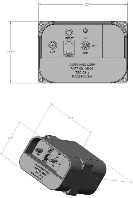
Figure 1: Front view of ELT
Figure 2: 3-D view of ELT
11 |
12 |

1.4BATTERY REPLACEMENT INSTRUCTIONS
1.4.1ELT MAIN UNIT BATTERY REPLACEMENT INSTRUCTIONS
All batteries are strongly advised to be serviced by Ameri-King or its authorized service centers. End users may return the entire ELT for replacing the batteries and post functional tests.
The Ameri-King Corp. Model AK-451 ELT is designed to use only with Ameri-King lithium battery packages which have been tested per TSO-C126, TSO-C91a requirements.
The use of any other battery will void all warranties of the ELT by Ameri-King Corp. The ELT does not meet the requirements of TSO-C126, and TSO-C91a or FAR 91.52 if used with any other type of battery. Using any other battery is not allowed (forbidden).
The Ameri-King Battery Pack has a 10 years shelf life and 5 years useful life. It will last for 78 hours at -20 deg C, at end of 5 years battery life.
FAR 91.52 (d) (i) requires that ELT batteries be replaced when the transmitter has been in use for more than one cumulative hour.
The label sticker for expiration date of the batteries must be affixed on the outside of the ELT battery case and recorded in the aircraft logs.
|
|
|
WARNING |
|
|
|
||
|
|
USE ONLY DURING SITUATIONS OF GRAVE |
|
|
|
|||
|
|
|
AND IMMINENT DANGER! |
|
|
|
||
LITHIUM BATTERY PACK – NON-RECHARGEABLE |
|
|||||||
P/N 4500010 -1 |
FOR USE ON Model AK-451-(AF)(AP)(S) |
|
||||||
RTCA DO-160E Environmental Categories |
|
|||||||
F1XB(227)(227)(227)XXXXXXXXXXXXXXXXXX |
|
|||||||
Replace battery pack |
Replace Main Batteries |
|
|
|||||
|
|
|
|
|
||||
after one culmulative hour |
By Date: _________ |
|
|
|||||
of use or by date shown: |
|
|
||||||
*Battery type: Lithium LiMn02 |
|
|
|
|
|
|||
|
|
|
|
|
|
|
|
|
|
|
|
|
|||||
|
NEVER CHARGE, SHORT CIRCUIT, PUNCTURE, |
|
|
|
||||
|
|
DEFORM, INCINERATE, OR OPEN. DO NOT |
|
|
||||
|
SUBMERGE IN WATER OR HEAT ABOVE 85OC. |
|
Battery Box Silkscreen |
|||||
|
|
|
REMOVE WHEN DISCHARGED |
|
||||
|
|
|
|
|
|
|
|
|
|
|
|
|
|
|
|
|
|
The owner or operator may perform Battery replacement provided that the accessibility, removal and reinstallation of the ELT can be considered “simple” as prescribed in Advisory Circular 91-44A, Paragraph 8.a (See Appendix B).
The following is a step-by-step instruction for replacing ELT Battery Pack P/N 4500010-( ) Series:
1.Using the 3/32” Hex Driver supplied with the ELT, remove the 4 retaining screws and split lock washers that attach the battery case to the ELT Transmitter Assembly (See Figure15).
2.Insure both battery connectors are locked-in properly by its tab. Verify the battery pack voltage is 13 +/- 0.5 VDC
Ensure that the gasket is in place (See Figure 4).
3.Place the Transmitter Assembly face down on a bench. Press down on the battery case to compress the battery contact springs. Replace the four battery retaining screws and lock washers and evenly tighten until the battery case is pulled flat against the Transmitter Assembly.
4.Remove any existing battery replacement date labels from the battery case and install the new label you prepared in step 3 above in a readily visible location on the ELT.
5.After battery replacement, a transmitter function test must be performed as described in section 2.3 of this manual.
WARNING |
FOR AVIATION EMERGENCY USE ONLY. |
UNLICENSED OPERATION UNLAWFUL |
Figure 3: Battery Replacement for ELT Main Unit
Figure 4: Battery Replacement for ELT Main Unit (Actual View)
13 |
14 |
 Loading...