


AK-451-ELT

1
Document No. IM-451 Rev NC-4.1h
dated July 5, 2014
INSTALLATION AND OPERATION MANUAL
FOR
MODEL AK-451-( ) Series
406 MHz ELT Emergency Locator Transmitter with
GPS/NAV position
AMERI - KING CORPORATION
17881 Sampson Lane
Huntington Beach, CA 92648
Tel: (714) 842-8555
Fax: (714) 842-4235
Email: ameriking9@aol.com
www.ameri-king.com

2
REVISION TABLE
REVISION
DESCRIPTION
CHANGED
BY
APPROVED
BY
DATE
NC
First Release
T.N.
K. V.
4/4/07
NC-1
Add PLB
Programming
T.N.
K.V.
9/5/07
Para. 1.2.1 d) and
Product Pictures
added
Para. 1.2.4.1,
1.2.4.2, 1.2.4.3,
and 1.2.4.4
revised
NC-2
Para. 2.4.5
deleted
T.N.
K.V.
9/10/07
Add Volume 2
for AK-451-PLB
for clarity
NC-3
Para 1.2.1 c. and
3.1.c revised
T.N.
K.V.
9/11/07
Para 3.3.5 added
Volume 2, Para
4.1 &4.3.2
revised
NC-4
Para 1.2.1 b and
2.2.3 revised
T.N.
K.V.
9/26/07
NC-4.1
Para 1.2.2, 2.2,
2.4.6, FAA form
337, 2.5.1,
revised
TSO-C142
information,
RTCA DO-160E
form for TSO C227 deleted
QP
KV
6/16/08

3
NC-4.1a
Revise: Para
2.5.1 & 3.5 to
meet Canadian
compliances
QP
KV
10/22/08
NC-4.1b
EASA Review
updated
QP
KV
10/31/08
NC-4.1c
EASA, T.C.
approved
updated
QP
KV
11/26/08
NC-4.1d
Brazil Anatel
Approval
updated
T.N.
KV
11/27/08
NC-4.1e
Japan Approval
Certificates
added
T.N.
KV
11/30/08
NC-4.1f
FAA and EASA
Antenna
approvals added
T.N.
KV
01/27/12
NC-4.1g
Clarify statement
for battery pack
service
T.N.
KV
01/09/12
NC-4.1h
Delete Optional
Multi Axes G Sw
Provision
(-12)(-16)
(-13)(-19)
KV
KV
7/5/14

4
AK-451 ELT Sets *** with no GPS / NAV Position:
Ameri-King P/N
Description
Antennas
Included
AK-451-(AF)(AP)/
Whi/Por (AK-451-
2/2D) triple/dual Freq.
ELT Set for
General Aviation,
U.S.A. Registration
Whip Antenna P/N AK
451.017-1B
and
Portable Antenna P/N AK
451.017-4(S)
AK-451-(AF)(AP)/
Whi/Por (AK-451-
20/20D) triple/dual Freq.
ELT Set for
General Aviation, Canadian
Registration
AK-451-(AF)(AP)
/Whi/Por/WW
(AK-451-21/21DCountry) triple/dual
Freq
ELT Set for
General Aviation.
Worldwide, Europe/
Australia/ Asia/Africa
Registration.
AK-451-(AF)(AP)
/Rod3/Por
(AK-451-3)
ELT Set
for Business Jet Aircraft
Rod3 Antenna P/N AK
451.017-2A-1 and
Portable Antenna P/N AK
451.017-4(S)
AK-451-(AF)(AP)
/Rod4/Por
(AK-451-4)
ELT Set
for Business Jet Aircraft
Rod4 Antenna P/N AK
451.017-2A and Portable
Antenna P/N AK
451.017-4(S)
AK-451-(AF)(AP)
/Bla/Por
(AK-451-5)
ELT Set
for Transport Aircraft
Blade Antenna P/N AK
451.017-3A and Portable
Antenna P/N AK
451.017-4(S)
AK-451-(AP)
(AK-451-10)
ELT Set Auto Portable, with
portable soft case ONLY (no
other accessories included)
Portable Antenna P/N AK
451.017-4(S)
permanently attached to
the unit
AK-451-(S)
(AK-451-11)
ELT Survival, with portable
soft case ONLY (no other
accessories included)
AK-451-(AF)(AP)
/Heli/Whi/Por
(AK-451-15)
ELT Set for Helicopter
Whip Antenna** P/N AK
451.017-1B and Portable
Antenna P/N AK 451.017-
4(S)
AK-451-(AF)(AP)
/Heli/Rod3/Por
(AK-451-14)
ELT Set for Helicopter
Rod3 Antenna P/N AK
451.017-2A-1 and
Portable Antenna P/N AK
451.017-4(S)

5
AK-451 ELT Sets *** with GPS / NAV Position:
Ameri-King P/N
Description
Antennas
Included
AK-451-(AF)(AP) w/
GPS/Whi/Por
(AK-451-23/6) Triple Freq,
(AK-451-23D/6D) Dual Freq.
ELT Set, with GPS/NAV
Position, for General Aviation
Whip Antenna P/N AK
451.017-1B
and
Portable Antenna P/N
AK 451.017-4(S)
AK-451-(AF)(AP) w/
GPS/Rod3/Por
(AK-451-7)
ELT Set, with GPS/NAV
Position, for Business Jet
Aircraft
Rod3 Antenna P/N AK
451.017-2A-1
and
Portable Antenna P/N
AK 451.017-4(S)
AK-451-(AF)(AP) w/
GPS/Rod4/Por
(AK-451-8)
ELT Set, with GPS/NAV
Position, for Business Jet
Aircraft
Rod4 Antenna P/N AK
451.017-2A
and
Portable Antenna P/N
AK 451.017-4(S)
AK-451-(AF)(AP) w/
GPS/Blade/Por
(AK-451-9)
ELT Set, with GPS/NAV
Position, for Transport Aircraft
Blade Antenna P/N AK
451.017-3A
and
Portable Antenna P/N
AK 451.017-4(S)
AK-451-(AF)(AP) w/
GPS/Heli/Whip/Por
(AK-451-17)
ELT Set, for Helicopter, with
GPS/NAV Position.
Whip Antenna** P/N
AK 451.017-1B
and
Portable Antenna P/N
AK 451.017-4(S)
AK-451-(AF)(AP)w/ GPS /
Heli / Rod3 / Por
(AK-451-18)
ELT Set, for Helicopter, with
GPS/NAV Position.
Rod3 Antenna P/N AK
451.017-2A-1
and
Portable Antenna P/N
AK 451.017-4(S)
** Whip antenna must have separate approval for installation in a Helicopter (see para. 2.2.2)
*** Each Ameri-King ELT Set comes with dual Antennas, a FREE Soft Case (P/N SC-451) and
a FREE Accessory Set including Remote Switch Unit, Pre-Fabricated 25’ Wiring Harness
Assembly, Audio Buzzer, T-Splitter, and 6’ Coaxial Cable Assembly.

6
DOCUMENT NO.: IM-451 REV. NC- 4.1g
Model/Part
No.:
Fixed Whip
Antenna
AK
451.017-1B
406/121.5
MHz
Or Fixed Rod
Antenna
AK 451.017-
2A
406/121.5/243
MHz
Or Fixed
Blade Antenna
AK 451.017-
3A
406/121.5/243
MHz
Portable Whip
Antenna
AK 451.017-
4(S)
406/121.5/243
MHz
AK- 451-(AF)
AK-451(AF)(AP)
AK - 451-(AP)
AK - 451-(S)
S
S
-
-
S
S
-
-
S
S
-
-
M
M
M
APPLICABILITY
M: Mandatory. The respective model must be accompanied by this antenna.
S: Selective. The respective model must be accompanied by at least 1 of these
antennas.
- : Not applicable
4500010-1: Battery Package, Lithium, LiMnO2, 90 Hrs Lasting.
TS-451: Computer Test Set and ELT Coding Equipment for AK-451

7
TABLE OF CONTENTS
Revision Page ..................................................................................................2
Table of Contents.............................................................................................7
List of Figures ..................................................................................................12
SECTION I
GENERAL INFORMATION
1.1 Scope ............................................................................................14
1.2 Overview ...........................................................................................14
1.2.1 Description .................................................................................14
1.2.2 Application and Equipment Limitation ......................................17
1.2.3 Certification ...............................................................................18
1.2.4 Programming ..............................................................................18
1.2.4.1 User Location Protocols (Long Message) ...........................18
1.2.4.2 Standard Location Protocols (Long Message) ....................19
1.2.4.3 National Location Protocols (Long Message) .....................19
1.2.4.4 User (non-location) Protocols (Short Message) ..................19
1.3 Technical Characteristics ..................................................................19
1.4 Accessories supplied .........................................................................24
1.4.1 Installation kit ............................................................................24
1.5 License requirement ..........................................................................24
SECTION II
INSTALLATION AND TEST
2.1 Unpacking and inspecting equipment................................................25
2.2 Mechanical installation......................................................................25
2.2.1 ELT main unit location and installation .....................................26
2.2.1.1 ELT Location Determination...........................................26
2.2.1.2 Mounting tray and Clamp Holder installation .................29
2.2.2 Antenna location and installation ...............................................33
2.2.2.1 Antenna location determination.......................................33
2.2.2.2 Antenna installation .........................................................35
2.2.2.2.1 Whip Antenna Installation ....................................35
2.2.2.2.2 Rod Antenna Installation ......................................40
2.2.2.2.3 Blade Antenna Installation ....................................43
2.2.2.2.4 Integral Antenna Installation ................................46

8
2.2.3 ELT remote unit location and installation ...................... 48
2.2.4 Wiring interconnecting harness ...................................... 51
2.2.5 Audible Monitor Location and Installation .................... 54
2.2.6 Wiring cable Installation................................................. 55
2.3 Electrical installation ........................................................................ 55
2.4 Post installation test .......................................................................... 55
2.5 Battery installation and replacement ................................................ 68
2.5.1 ELT main unit battery installation & replacement.......... 68
2.5.2 ELT remote unit battery installation & replacement ...... 71
2.6 FAA Form 337 ................................................................................. 72
SECTION III
OPERATION
3.1 General ........................................................................................ 73
3.2 Operation ........................................................................................ 74
3.3 Transmitter Functional Test ................................................................. 74
3.3.0 Quick Operation Check ......................................................... 75
3.3.1 Main Switch ON/OFF/ARM Operation ................................. 76
3.3.2 Transmitter ID Programming and Self-Test .......................... 76
3.3.3 System Integration Test ......................................................... 77
3.3.4 Green ON Lights, Buzzer Sound, and Antenna check ........... 80
3.3.5 Transmitter Functional Test for ELT-(S) only ....................... 81
3.4 Periodic Maintenance (Instructions for Continued Airworthiness) .... 86
3.4.1 Secure Inspection ................................................................... 86
3.4.2 Corrosion Inspection for Coaxial Cable ................................ 86
3.4.3 Corrosion Inspection for Remote Wiring Modular Cable ...... 86
3.4.4 Expiration Date Check ........................................................... 86
3.4.5 Battery Leakage Check .......................................................... 86
3.4.6 Operational Test..................................................................... 86
3.4.7.1 G-Switch Check ..................................................................... 86
3.4.7.2 Antenna Check....................................................................... 87
3.4.8 Verification of Digital Message ................................ ............. 87
3.4.9 Verification of Registration ................................................... 89
3.4.10 Verification of ELT/GPS interface ........................................ 90
3.4.10.1 ELT to GPS Interface Information ................................. 90
3.4.10.2 ELT/GPS Interface Communication Formats ................. 91
3.4.10.3 ELT/FMC Interface and Checkout Process .................... 92

9
3.4.10.4 24-Bit Address Installation Test (mandatory for
Installations reprogramming
by Ameri-King’s authorized dealer) ................................92
3.4.10.5 GPS Position Test ............................................................93
3.5 Periodic Maintenance (Instructions for Continued Airworthiness)
for Canadian Installation ................................ ................................ .......94
3.5.1 Regular Periodic Maintenance Test ........................................95
3.5.2 Power output test, Performance Testing ................................ .95
3.5.3 Frequency Test / Current Draw Test, Performance Testing ...97
3.5.4 Audio Modulation, Performance Testing ...............................99
3.5.5 Transmitter Functional Test ....................................................99
3.5.6 Performance Test Marking and Log Book Entry ....................99
3.5.7 Shipping ..................................................................................99
SECTION IV
REGISTRATION AND RESPONSIBLE USE
4.1 Registration .......................................................................................100
4.1.1 Registration importance ......................................................100
4.1.2 Where to register .................................................................100
4.1.3 Registration in the United States ................................ .........100
4.1.4 Registration in Canada ........................................................101
4.1.5 Registration outside of the United States and Canada ........101
4.1.6 Change of ownership or contact information ......................101
4.1.7 Lost ELT’s ..........................................................................102
4.1.8 Stolen ELT’s .......................................................................102
4.2 Responsibility ....................................................................................102
4.2.1 Responsible Use ..................................................................102
4.2.2 Preventing false alarms .......................................................103
4.2.3 Report false alarms..............................................................103
4.2.4 To report false alarms in the United States
contact any of the following ................................................103
SECTION V
WARRANTY AND SERVICE
5.1 Limited Warranty ..............................................................................104
5.2 Repair Service ...................................................................................105
5.3 Factory Comprehensive Test Service ................................................105

10
APPENDIX A
Retrofit Instructions from AK-450 to AK-451 .......................................................106
APPENDIX A.1
Quick Operation Check ..........................................................................................114
APPENDIX B
Periodic Maintenance Check List with Compliance Cross References ..................115
APPENDIX C
FAA Action Notice A 8150.3 Emergency Locator Transmitter recommended
Supplemental Inspection Procedure (FAR Part 91 Operations) ..............................119
APPENDIX D
Excerpt from FAA AC 91-44A Paragraph 8.a which defines when Battery
Replacement may be done under FAR 43.3 (h) as Preventive Maintenance ..........123
APPENDIX E
FAA Advisory Circular AC.13-2B, Section 37.C ..................................................124
APPENDIX F
Registering a 406 MHz Beacon for U.S.A..............................................................125

11
APPENDIX G
International 406 MHz Beacon Registration Database (IBRD)
Countries Allowing Individual Registration ........................................................... 128
APPENDIX H
ELT Coding Programming, ID Reader and Maintenance Test, P/N TS-451 .......... 133
APPENDIX I
RTCA DO-160D Environmental Qualification Forms ........................................... 145
APPENDIX I.1
RTCA DO-160E Environmental Qualification Forms ........................................... 147
APPENDIX J
Approval, FAA TSO C-126 / C-91a Equipment Approval dated 07/24/2008 ........ 150
Approval, Incomplete Technical Standard Order for ELT Antenna TSO C126
and C91a dated 11/4/2010 .................................................................... 152
Approval, EASA ETSO 2C-126/2C-91a EASA.IM.21O.1102
dated 11/20/2008 .................................................................................. 154
Approval, EASA ETSO 2C-126/2C-91a EASA.IM.21O.10033545
dated 1/27/2011 .................................................................................... 155
Approval, Transport Canada dated 11/26/2008 ...................................................... 156
Approval, Industry Canada, ID 2474A-A451PLAFAPS, dated 11/06/2008 .......... 158
Approval, Brazil Certificado Anatel, dated 03/31/2009 ......................................... 159
Approval, EASA Minor Change Approval 10027068, dated 9/3/2009 .................. 160
Approval, EASA Minor Change Approval 10027068 Rev 1, dated 1/10/2011 ...... 162
Approval, EASA Minor Change Approval 10026866, dated 8/18/2009 ................ 165
Approval, EASA Minor Change Approval 10026863, dated 8/18/2009 ................ 167
Approval, EASA Minor Change Approval 10026863 Rev 1, dated 11/15/2010 .... 169
Approval, EASA Minor Change Approval P-EASA.A.C.12674
dated 7/24/2009 .................................................................................... 171
Approval, Austria for "Historic Aircraft" like PA-18, 19 Series,
Bücker T131, JOB 15, CSS13, dated 4/16/2010 ................................... 174
Email Response from EASA to Ameri-King re. Acceptability of FAA
Form 8130-3 Export Form in EU Europe Union dated 10/2/2009 ....... 220
Approval, Japan Civil Aviation Board TSO C-126 and C91a ................................ 222
Approval, Japan Ministry of Internal Affairs and Communications Certificate ..... 224
Approval, COSPAS-SARSAT Type Approval Certificate No.179
dated 09/24/2007 .................................................................................. 226
APPENDIX K
Material Safety Data Sheet for Battery ................................................................... 229

12
List of Figures
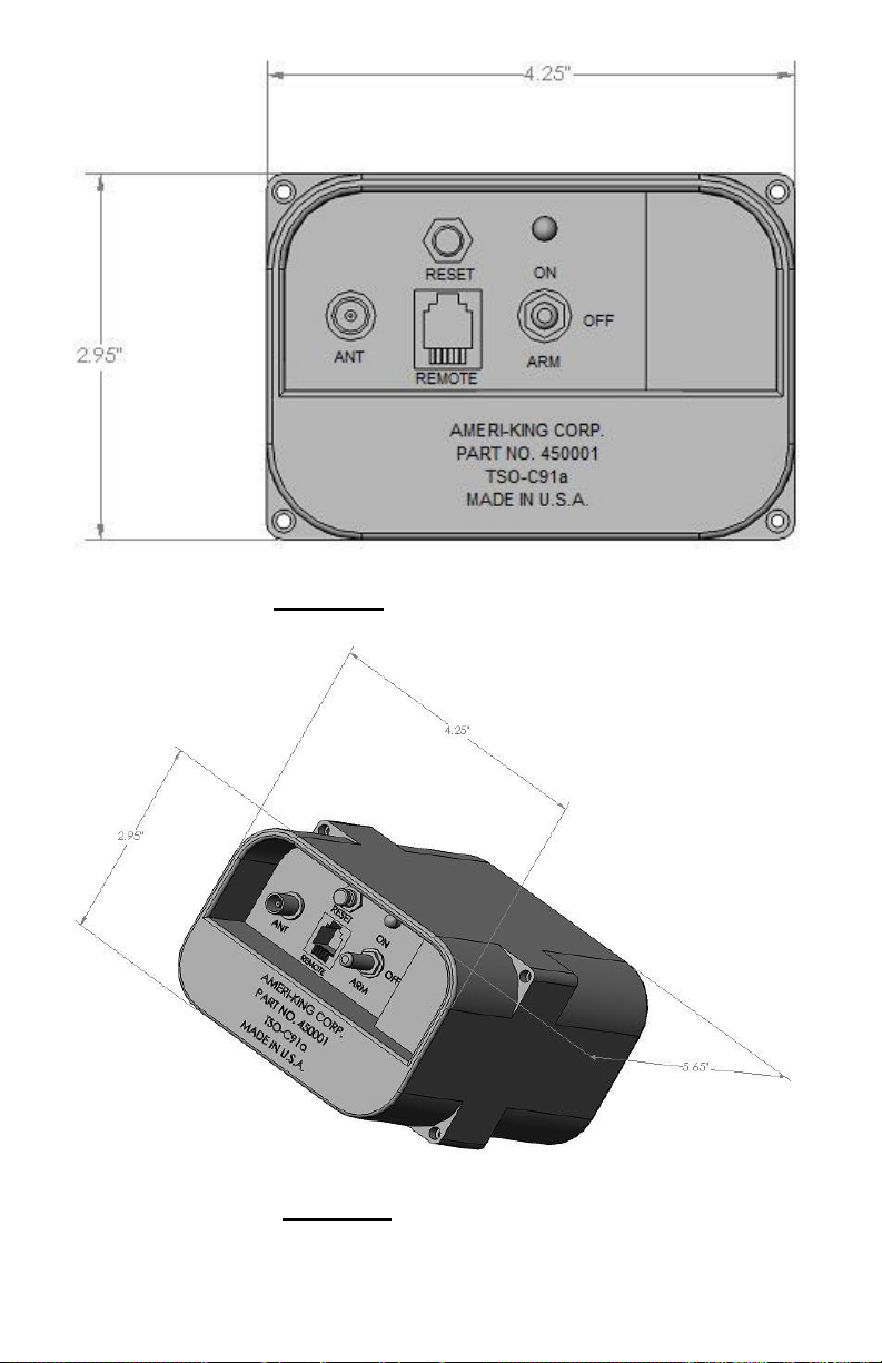
Figure A: Front view of ELT .......................................................................... 23
Figure B: 3-D view of ELT ............................................................................. 23
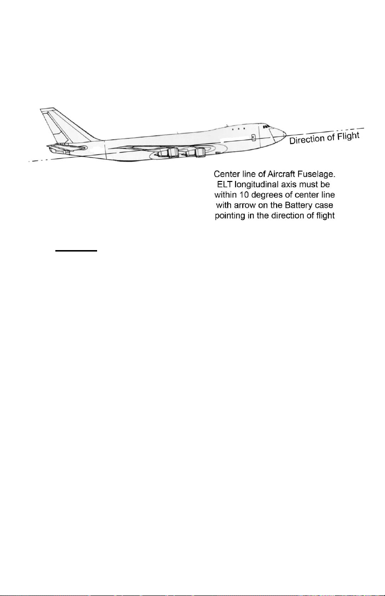
Figure 1: Direction Determination for Fixed Wing Aircraft ........................... 28
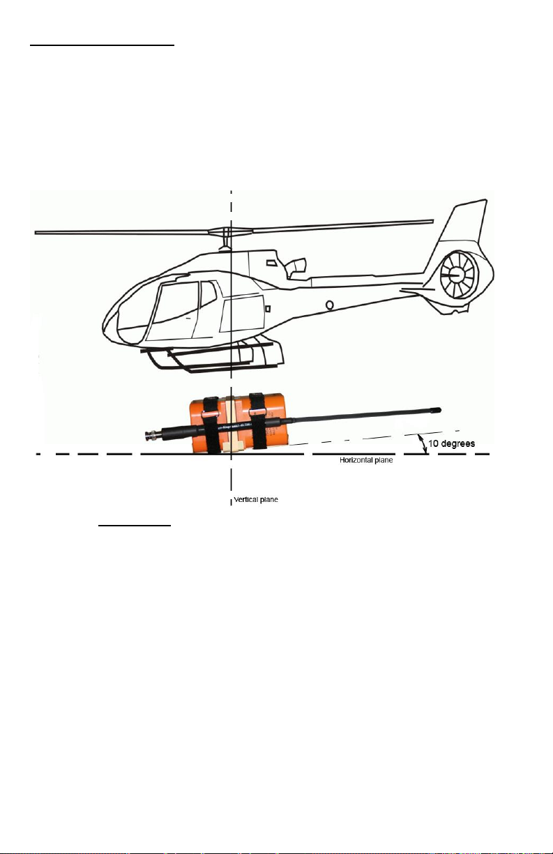
Figure 1.1: Direction Determination for Helicopter ....................................... 29
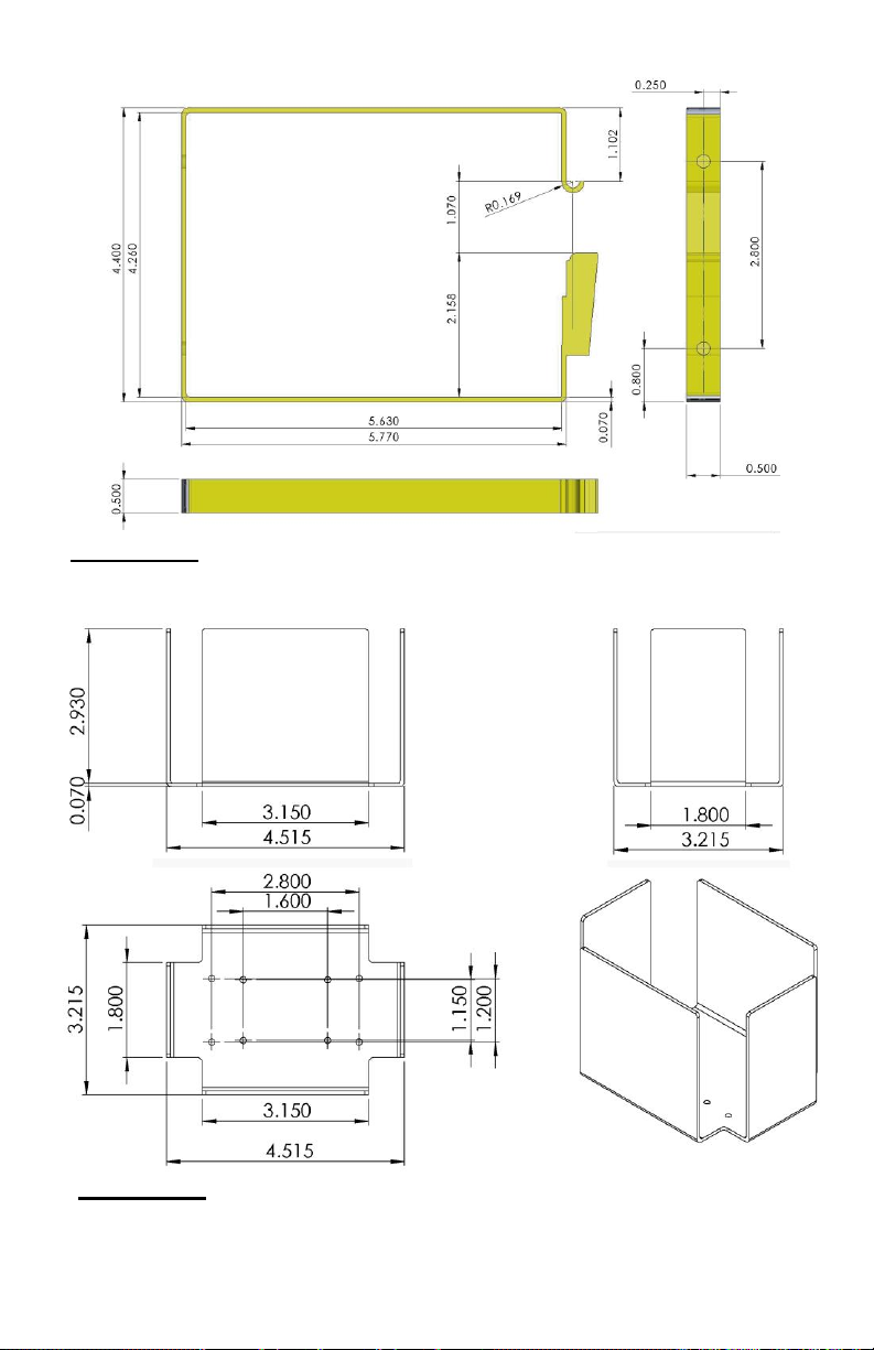
Figure 2.1: Mounting Tray for ELT- (AF)(AP). P/N 450 013 ........................ 31
Figure 2.1a: Mounting Tray for ELT- (AP) with integral antenna & ELT-(S)
P/N 450 013-2 ........................................................................... 30
Figure 2.1.1: Optional Adapter Tray for ELT- (AF)(AP). P/N 450 013-1 ...... 38
Figure 2.1.2: ELT with mounting tray, holder, and adapter tray............. 39
Figure 2.2: Holder for ELT- (AF)(AP) P/N 450 014 ...................................... 31
Figure 2.2a: Holder for ELT-(AP) with integral antenna
P/N 450 014-1 ........................................................................... 30
Figure 3: Mounting Tray with Clamp Holder for ELT- (AF)(AP) ................. 32
Figure 4: Reserved
Figure 5: Antenna ground plane for nonmetallic aircraft ................................ 34
Figure 6: Whip Antenna (AK 451.017-1B) .................................................... 37
Figure 6.1: Reserved
Figure 7: Rod Antenna (AK 451.017-2A) ...................................................... 41
Figure 7.1: Rod Antenna (AK 451.017-2A-1) ................................................ 42
Figure 8: Blade Antenna (AK 451.017-3A) .................................................... 46
Figure 9: Integral Portable Whip Antenna (AK 451.017-4(S))
(Ant ground plane is not required) ................................................ 47
Figure 10: ELT Remote Switch Installation ................................................... 49
Figure 10.1: Mounting bracket for ELT Remote Unit (Continued) ................ 49
Figure 11: Remote Audio Buzzer Monitor P/N 451018 ................................ 50
Figure 11.1: Buzzer may be fastened directly onto the Remote Switch Unit . 51
Figure 12.1: Interconnecting Wiring Cable between ELT Remote Unit
and Main Unit, Part No. 4510041 ............................................. 52
Figure 12.2: Interconnecting Wiring Cable between ELT Remote Unit
and Main Unit, Part No. 4500041 ............................................. 53
Figure 13: Verify parameter setting ................................................................ 60
Figure 14.1a: Wiring diagram for AK-451 with 4-wire interconnecting
ELT Main Unit and Remote Switch Unit .................................. 62
Figure 14.1b: Wiring diagram for AK-451 with 2-wire interconnecting
ELT Main Unit and Remote Switch Unit .................................. 63
Figure 14.1c: Wiring Diagram for retrofitting AK-451 with 4-wire+
interconnecting ELT Main Unit and Remote Switch Unit,
Artex, Pointer, Kannad, ACK Tech, etc……………………………64

13
Figure 14.1d: Wiring Diagram for retrofitting AK-451 with 2-wire
interconnecting ELT Main Unit and Remote Switch Unit,
D&M, Narco, Joliet, etc. .......................................................................... 65
Figure 14.2a: Wiring Diagram for AK-451 with GPS Position
and 3-inch T adapter with 4-wire interconnecting ELT Main Unit
and Remote Switch Unit........................................................................... 66
Figure 14.2b: Wiring Diagram for AK-451 with GPS Position
and 3-inch T adapter with 2-wire interconnecting ELT Main Unit
and Remote Switch Unit........................................................................... 67
Figure 15: Battery Replacement for ELT Main Unit .............................................. 69
Figure 16: Battery Pack Replacement for ELT Main Unit (Actual View) ............. 70
Figure 16.1: Battery Cell Replacement for ELT Main Unit (Actual View) ........... 70
Figure 17: Battery Replacement for ELT Remote Unit .......................................... 71
Figure 18: ELT Front Panels-Main Unit and Remote Unit .................................... 78
Figure 19: ELT-(AP)(S) complete assembly with antenna ..................................... 83
Figure 20: Verify parameter setting ........................................................................ 93

14
SECTION I
GENERAL INFORMATION
1.1 SCOPE
This manual contains information necessary for the installation, test and operation of
the model AK-451, Emergency Locator Transmitter, manufactured by Ameri-King
Corporation, California, U.S.A.
1.2 OVERVIEW
1.2.1 Description
The Ameri-King AK-451-( ) Series is a FAA TSO’d approved, EASA ETSO’d
approved, 406 MHz ELT Emergency Locator Transmitter, Types (AF) Automatic
Fixed, (AP) Automatic Portable, (S) Survival. It transmits aircraft GPS/NAV position
data, immediately and accurately, on triple (406 Satellite /243 Military /121.5
Civilian) MHz frequencies. The supreme advantage feature is the aircraft GPS/NAV
Latitude / Longitude exact position shall be transmitted, within 1 minute, on the very
first burst, without waiting for a Polar Orbiting Satellite (could be up to 4 hours).
Enhance the accuracy significantly, for the ground search area, from 1-2 kilometers
(non GPS/ NAV Position) to 22 meters typical (with GPS/NAV Position). Having a
triple frequency insures your distress message reaches both NOAA Satellite
Operation and US Air Force AFSR Ground Operation, Search and Rescue Team, with
100% fully confidence, due to transmitting on both 243.0 MHz Military and 121.5
MHz Civilian bands, for immediate ground search dispatch, narrowing the searching
time.
The AK-451 ELT Emergency Locator Transmitter is micro controller based
equipment. It is extremely reliable equipment, designed to meet TSO-C126 and TSOC91A requirements, batteries operated and self contained.
The ELT Emergency Locator Transmitter is designed only for emergency use. The
model AK-451 may be used as one or more of the following ELT types:
a. Automatic Fixed-ELT (AF):
The ELT (AF) is designed to be permanently attached to the aircraft before and after a
crash. Aural and flashing light monitors are provided to alert the flight crew that the
ELT has been activated and is transmitting. It is designed to aid the Cospas-Sarsat
satellite and SAR teams in locating a crash site.
The model AK-451 (AF) consists of an ELT main unit, an aircraft-fixed antenna,
coaxial cable assembly, remote switch unit, interconnect wiring assembly, a T-adapter
connector, an audible buzzer monitor, a mounting tray, and clamp holders.
The ELT (AF) has an automatic activation G-Switch. It is activated automatically
upon a crash or manually operated.

15
b. Automatic Portable-ELT (AF) (AP) with dual antennas:
The ELT (AF) (AP) is designed to be rigidly attached to the aircraft before the crash,
but readily removable from the aircraft after a crash. It functions as an ELT (AF)
during a crash sequence. The aircraft mounted antenna may be disconnected and a
portable antenna (mounted on the ELT mounting tray) is then attached to the ELT.
All mentioned procedures require no tools. Flashing light indicator on the ELT is
provided to alert the user that the ELT has been activated and is transmitting. The
ELT can be tethered to a survivor or a life raft. It is designed to aid the Cospas-Sarsat
satellite and SAR teams in locating the crash site or survivor(s).
The model AK-451 (AF) (AP) consists of an ELT main unit, an aircraft-fixed
antenna, a portable antenna, coaxial cable assembly, remote switch unit, interconnect
wiring assembly, a T-adapter connector, an audible buzzer monitor, a mounting tray,
clamp holders and portable soft case..
The ELT (AF)(AP) has an automatic activation G-Switch. It is activated
automatically upon a crash or manually operated.
If for any reason, a fixed mounting is not required, the ELT (AF)(AP) can be used as
a Portable Device, due to it ‘s manual operated hand use Portability. Check Local
and/or national regulations for this issue.
c. Automatic Portable-ELT (AP) with integral antenna:
The ELT (AP) is designed to be rigidly attached to the aircraft before the crash, but
readily removable from the aircraft after a crash. It functions as an ELT (AF) during
a crash sequence. All mentioned procedures require no tools. Flashing light indicator
on the ELT is provided to alert the user that the ELT has been activated and is
transmitting. The ELT can be tethered to a survivor or a life raft. It is designed to aid
the Cospas-Sarsat satellite and SAR teams in locating the crash site or survivor(s).
The model AK-451 (AP) consists of an ELT main unit with an integral antenna,
remote switch unit, interconnect wiring assemblies, an audible buzzer monitor, a
mounting tray, clamp holders and portable soft case.
The ELT (AF) has an automatic activation G-Switch. It is activated automatically
upon a crash or manually operated.
If for any reason, a fixed mounting is not required, the ELT (AF)(AP) can be used as
a Portable Device, due to it ‘s manual operated hand use Portability. Check Local
and/or national regulations for this issue.

16
d. Survival-ELT (S, Category A):
The ELT (S) shall survive the shock, impact and crush tests, after a crash. This type
of ELT does not have automatic activation G-Switch and is intended to be removed
from the aircraft.
It functions as an ELT (P). Flashing light indicator on the ELT is provided to alert the
user that the ELT has been activated and is transmitting. The ELT can be tethered to a
survivor or a life raft. It is designed to aid the Cospas-Sarsat satellite and SAR teams
in locating the crash site or survivor(s).
The model AK-451-(S) consists of an ELT main unit with integral antenna and a
portable soft case.
The ELT (S) has no automatic activation G-Switch. It is activated manually only.

17
The Main Unit features include:
ON / OFF / ARM Main Switch
Green ON Light
RESET Push Button Switch
The Remote Unit features include:
ON Push Button Switch
Green ON Light
RESET Push Button Switch.
All functions of the AK-451 are under micro-controller control. A self-test routine
checks ELT operation and installation, then presents the results as visual and auditory
'error code' to aid in troubleshooting and to indicate status. Software is approved per
requirements of RTCA/DO-178B for level D software.
The battery pack consists of four D-size lithium, and is field replaceable. Rated life is
5 years or one hour of use, whichever comes first, as specified by FAR 91.207(c).
Installation kits are available that contain all major components needed to install the
beacon.
1.2.2 Application and Equipment Limitation
This manual constitutes FAA approved data as described in AC 43.9-1F, paragraph
(h)(2) and AC 43-210, chapter 2, paragraph 201(a)(6) for major alterations. Not all
installations are “major”; consult your local FAA ACO for clarification.
In Canada, Installation of an ELT in an aeronautical product is carried out under a
Supplemental Type Certificate (STC). This is a separate regulatory requirement and
should therefore refer to Ameri-King Document No. ICA-451 for the Operations and
Instructions for Continued Airworthiness (ICA).
The conditions and tests required for TSO approval of this article are minimum
performance standards. It is the responsibility of those desiring to install this
article on a specific type or class of aircraft to determine that the aircraft
installation conditions are within the TSO standards. TSO articles must have
separate approval for installation in an aircraft. The article may be installed
only if further evaluation by the applicant documents an acceptable installation
and it is approved by the FAA Administrator. The article may be installed only
if performed under 14 CFR parts 43 or the applicable airworthiness
requirement. For installations outside of the US, contact your local civil aviation
authority for guidance (Ref. TSO-C126 paragraph D).
Lithium battery safety concerns include the possibility of fire, venting violently,
and venting of toxic gases (Ref. TSO-C126 paragraph 5.a.(2)).

18
The AK-451 ELT described in this manual was designed, tested and certified as a
complete system including the following components:
ELT Transmitter w/ integral battery
ELT Mounting Tray and clamp Holder
ELT Antenna and Coaxial Cable Assembly
ELT Remote Switch and Remote Wiring Cable Assembly
ELT Audible Buzzer Monitor unit and T-Adapter Connector
Note:
Only Ameri-King approved system components may be used for a TSO approved
system.
1.2.3 Certification:
The AK-451 has been certified to the following:
FAA TSO-C126, C91a, C142
ETSO-2C126 per European Aviation Safety Agency (EASA)
FAR Part 91 – mandatory automatic ELT requirements
Cospas-Sarsat T.001
47 CFR Part 87 (FCC requirements) Note: Per FCC regulations 47
CFR § 2.902, the ELT is tested per “Verification” method.
Note:
The AK-451 is certified to meet the requirements of FAA TSO-C126, TSO-C91a and
EASA ETSO-2C126 per EUROCAE ED-62. For use outside the US or EASA
member states, contact your local civil aviation authority for ELT requirements.
1.2.4 Programming:
Ameri-King will program in any protocol at no charge. The AK-451 supports all
available worldwide ELT protocols in long message and short message. For a
complete ELT protocol, please see C/S document G.005 and T.001 available at
www.cospas-sarsat.com. For use outside the US, please contact your local civil
aviation authority for accepted or required programming protocols.
The AK-451 supports the following protocols:
1.2.4.1 User Location Protocols (Long Message):
Coding ELT with beacon serial identification
Coding ELT with aircraft operator designator and a serial number
Coding ELT with aircraft 24-bit address
Coding ELT with aircraft nationality and registration marking

19
1.2.4.2 Standard Location Protocols (Long Message):
Coding ELT with 24-bit address
Coding ELT with Type approval number and a serial number
Coding ELT with aircraft operator designator and a serial number
1.2.4.3 National Location Protocols (Long Message):
National Location Protocol (Coding for ELTs)
1.2.4.4 User (non-location) Protocol (Short Message):
Serial User Protocol Coded with ELTs Unique Beacon Serial Number.
Serial User Protocol Coded with the Aircraft Operator Designator and a
Serial Number.
Serial User Protocol Coded with the Aircraft 24-Bit Address.
Aviation User Protocol Coded with the Aircraft Nationality and
Registration Marking.
Note 1: The AK-451 is pre-programmed at the factory using ELT with C/S type
approval number and serial number, Standard Location Protocol (Long Message) or
Serial User Protocol (Short Message), for US aircraft.
Note 2: The AK-451 is pre-programmed at the factory using ELT with 24 Bit aircraft
address, Standard Location (Long Message) or Serial User (Short Message),
for Canadian aircraft. Your 24 Bit aircraft address, may be obtained from
http://www.tc.gc.ca/aviation/activepages/ccarcs/aspscripts/en/quicksearch.asp
Note 3: There is no electronic connection between TCAS or Mode S systems and the
ELT, only the ID number is common. The ELT may accept aircraft GPS/NAV
Lat/Long position data, then transmits the position data on the 406 MHz digital long
messages.
1.3 TECHNICAL CHARACTERISTICS
SPECIFICATIONS: CHARACTERISTICS:
APPROVALS: FAA TSO-C126 / C91a, C142
and EASA ETSO-2C126/2C91a
BATTERIES:
4500010-1: Battery Pack, Lithium, LiMnO2, 90 Hrs lasting, 4D cells
Note: For Canadian aircraft installation, use 4500010-1 only.
4500010-2: Battery Pack, Lithium, LiSO2, 87 Hrs lasting, 4D cells

20
PHYSICAL CHARACTERISTICS:
SIZE AND WEIGHT:
Main Unit: (4.27”Wx2.95”Hx5.64”L) 1lbs 14oz
Remote Unit: (1.58”W x 0.65”H x 2.00”L) 1.0 oz
Transport Blade type, 451 017-3: 600 Knots airspeed, 1.4 lbs
Business Rod type, 451 017-2: 350 Knots airspeed, 0.5 lb
General Aviation whip type,
451 017-1: 300 Knots airspeed, 0.25 lb
Portable Antenna, 451 017-4: (17”L) 4.0 oz
Mounting Tray & Clamp holder: (4.51”W x 0.75”H x 5.87”L) 4.0 oz
MOUNTING HOLE SPACING:
Mounting Tray: 4 Trapezoid Corners (L1=2.76”; L2=1.76”; H=2.01”)
Remote Unit: 4 Rectangular Corners (1.825”W x 0.490”H)
Fixed Antenna: 7 / 5 / 1 Holes (0.500” Diameter) for Blade / Rod / Whip
respectively
CASE AND COLOR:
No Sharp Edges, High Impact, Flame Retorted, Fire Resistant, Waterproof, High,
Temperature ABS Plastic, Safety International Orange Color.
GENERAL SPECIFICATIONS (STANDARD CONDITIONS):
TRANSMITTER:
Operating Frequencies: 406.028 MHz ± 0.001 MHz
121.500 MHz ± 0.005 %
243.000 MHz ± 0.005 %
(Note: AK-451-2D/6D/20D/21D/23D will turn off 243 MHz)
Short term stability ≤ 2 x 10⁹/100ms
Medium slope -1 to +1x10⁹/min
Medium Residual variant ≤ 3 x 10⁹
Modulation
Characteristics: Audio Sweep Frequency: Download
Sweeping: (1600-300) Hz
Sweep Rate: 3 Hz ± 1 Hz
Modulation Factor: More than 0.85
Occupied Bandwidth: Less than 25 Hz
Voice Modulation: Included
Modulation Duty Cycle: (33-55) % Square Wave AM Continuous
Peak Effective Radiated50mW @ 121.5 MHz
RF Power (PERP): 50mW @ 125/243.0 MHz
5W +/- 1.58W @ 406.028 MHz
(35.34 to 38.18) dBm @ 406.028 MHz

21
Equivalent Isotropic 100mW (-10dBW) @121.5/243.0 MHz
(min)
Radiated Power (EIRP): 6dBW ± 4dB @406.028 MHz (max)
Emission Designator: 16K0G1D for 406.028 MHz
3K20A3X for 121.5 MHz
BATTERY REQUIREMENTS:
Transmitter Main Unit: Battery Pack consists of 4 cells, LiMnO2 or
LiSO2,“D” Size
Remote Unit: DURACELL DL 1/3 NB, or Equiv. Lithium Cell
AUTOMATIC CRASH ACTIVATION:
Velocity Change of 2.3 ± 0.3 G (4.5 ± 0.5 FPS) per TSO C-126 (DO204A) and ETSO-2C126 (EUROCAE ED-62) requirement.
ANTENNA RADIATION CHARACTERISTICS:
Radiation on 121.5, 243.0 MHz, and 406.028 MHz
Vertically polarized & Omni directional in the Horizontal Plane.
CRASHWORTHINESS: 100g, 23 ms, 6 directions
ACTIVATION MONITOR:
Manual ON and RESET functions are located on both ELT Main Unit and Remote
Unit. The two Green ON lights flashing, located on the ELT Main Unit and Remote
Switch Unit and a buzzer are to indicate when the ELT is transmitting. Both ELT
Main Unit and Remote Unit are self-powered by their internal batteries. Automatic
activation is remained, regardless whether the Cable Interconnect between the Main
Unit and the Remote Unit is open or shortened.
GPS INTERFACE PROTOCOL: Aviation RS-232
(Latitude/ Longititude Insert Messages) Baud Rate (fixed): 9600
Parity: None
Data Bits: 8
Stop Bits: 1
Garmin International Inc.:
• All Series: 150/ 250/ 400/420/430/ 500/520/530
Honeywell Bendix-King Inc.:
• KLN 88, KLN89, KLN89B, KLN 90, KLN90B, KLN94, KLN900.

22
Arnav Systems Inc.:
• R50, R50i, STAR 5000, FMS 5000, MFD (Multi-Functional Display).
II Morrow:
• FLYBUDDY, 2001 NMS
Trimble Nav Inc.:
• NAV 1000, NAV 2000, TNL 2100, and TNL3100. The following Trimble systems
all require a RS-422 to RS-232 adapter: NAV 3000, TNL 1000, TNL 2000, TNL
2000A, TNL 3000, 2000 APPROACH, 2000 APPROACH PLUS, 2101
APPROACH, 2101 APPROACH
PLUS, 2101 I/O APPROACH, 2101 I/O APPROACH PLUS.
ENVIRONMENTAL TEST SPECIFICATIONS:
RTCA DO-204 ; DO-183
TSO-C126/C91a, RTCA DO-160E ENV. CAT.: F1XBA (204/183)
(204/183)XR(204/183)XXSXXXXAC(204/183)BXXXX (204)
TEMP. AND ALTITUDE: Category F1
Low Temperature: -20°C Operating; -55°C Storage.
High Temperature: +55°C Operating; +85°C Storage.
OPERATING LIFE: 5W @ 406.208 MHz for 24 hrs @ 20°C
50mW @ 121.5 MHz
50mW @ 243.0 MHz
(Minimum Requirement throughout a 50
hour period at –20°C)
TEMP VARIATION: Category B, 10°C minimum per minute
HUMIDITY: Category A, 95% RH, 50 hours
operating
SHOCK: 500G, 4 ± 1msec
IMPACT: Penetration of 55 lbs mass, 6 drops, 4
surfaces
CRUSH: 1000 lbs, 4 surfaces
VIBRATION: 10G, Sinusoidal, (5-2000) Hz, 3 axes
WATERPROOF: Category R, 15 minutes Spray, 6 sides
IMMERSION SALT WATER: Category S, 24 hours Immersion, 160
hours at + 55°C
SALT SPRAY: Category S, 48 hours exposure to the
Salt Fog, and 48 hours drying
23
Figure A: Front view of ELT
Figure B: 3-D view of ELT

24
1.4 ACCESSORIES SUPPLIED
1.4.1 INSTALLATION KIT:
PART NO. DESCRIPTION
4500010-1 Lithium Battery Pack LiMnO2
or 4500010-2 Lithium Battery Pack LiSO2
450004 Remote Switch Control Unit
4510041 or 4500041 Remote Wiring Cable Assy.
450013 / 450013-1 Mounting Tray
451014 / 450014 Clamp Holder
4510171 Coaxial cable assembly
451018 Audible Buzzer Monitor
4510181 T-Adapter connector
AK 451.017(-1B)/(-2A)/(-2A-1)/
(-3A)/(-4(S)) Antenna Assembly
4510131 Optional Floating Collar
SC-451 Soft Case
SC-451-T Tether
1.5 FCC LICENSE REQUIREMENT:
In the U.S.A.: Not required per FCC.
Note: Radio station license of the aircraft is required by telecommunication
regulations in several European countries.

25
SECTION II
INSTALLATION AND TEST
2.1 UNPACKING AND INSPECTING EQUIPMENT
Handle with extreme care when unpacking the equipment. Visual inspection of the
equipment for evidence of damage incurred during shipment. Any claim should be
promptly filed with the transportation company. Save the shipping container to
substantiate the claim. Retain the container and packaging material for possible
future use.
2.2 MECHANICAL INSTALLATION
The ELT is designed with the installer in mind. All accessories, which are required
for complete ELT system installation, are provided, including Mounting Tray, Clamp
Holder, Coaxial Cable Assembly and Wiring Cable Assembly.
Because of the critical nature of an ELT, it is very important that the installation be
performed according to the following instructions. Installation of the ELT is
somewhat unique, as is the installation of any TSO-C126 and TSO-C91a ELT; it
requires experience in sheet metal work and avionics. Only licensed technicians
should install the ELT.
Many problems associated with the older ELTs were due to poor installation.
Therefore, duplicating a previous ELT installation with the AMERI-KING ELT may
not be acceptable.
Installations must be made by qualified personnel in accordance with FAA
regulations. Duplicating a previous installation may not be acceptable. Refer to the
Department of Transportation Regional ACO for detailed information.
Please refer to FAA AC 43.13 for guideline.
RTCA DO-182 recommends:
"All ELT system components which must survive a crash intact, should be attached to
the airframe in such a manner that the attachment system can support a 100g load ...in
the plus and minus directions of the three principal axes of the aircraft."
RTCA documents may be obtained from:
RTCA, Inc.
1828 L Street, NW
Suite 805
Washington, DC 20036
Tel: 202-833-9339
Fax: 202-833-9434
www.rtca.org
info@rtca.org

26
Note:
Installation in a pressurized aircraft constitutes a major modification. Consult the
Department of Transportation Regional Officer before proceeding.
Note:
Aircraft manufacturers may also have guidance on ELT installation; refer to and
follow any applicable Type Approval or STC data for your aircraft. If located outside
of the US, follow all applicable regulations for your national authority.
By signing either the aircraft logbooks or the FAA Form 337, you are stating that the
installation has been performed in accordance with the current FARs and with the
steps and procedures outlined herein.
In Canada, all installations must be performed in accordance with the Engineering
and Inspection Manual Part II, Chapter III, Section 3.12.
Remember: Your Professional installation may save someone’s life.
2.2.1 ELT MAIN UNIT LOCATION AND INSTALLATION
2.2.1.1 ELT LOCATION DETERMINATION:
Many of the original ELT installations are inadequate as far as unit location and
surface rigidity are concerned. Just because the “old” ELT was located in a particular
position doesn’t mean the “new” ELT should be located there as well.
The tail section of an airplane is least likely to be damaged during a crash and
therefore, it provides a good mounting environment for the ELT unit. Refer to Figure
1 for Direction Determination for Fixed Wing Aircraft and Helicopter, respectively.
Accessibility of the unit is an important factor in the location of the ELT. Mount the
unit as far aft as practical but where it can be easily retrieved for maintenance.
The mounting surface must be extremely rigid; therefore, mounting the ELT directly
to the aircraft skin is unacceptable.
Mounting an ELT directly to the aircraft skin induces “crash hiding” vibration and
provides a very poor structural mounting surface. The mounting location must be
able to support 100 pounds of force in any direction with no appreciable distortion in
the structure. It must also be able to withstand a 350-pound force in any direction
without tearing or breaking the aircraft structure.
Please refer to FAA AC 43.13 for guideline.

27
Following are the FAA guidelines for mounting a TSO-C91a ELT, per RTCA
DO-183 paragraph 3.1.8:
1. “The ELT shall be mounted to primary aircraft load carrying structures such as
trusses bullheads, longerons, spars, or floor beams.”
2. “The mounts shall have a maximum static local deflection no greater than 2.5
mm (0.1 in) when a force of 451 Newtons (100lbs) is applied to the mount in the most
flexible direction. Deflection measurements shall be made with reference to another
part of the airframe not less than 0.3 meters (3 feet) from the mounting location.”
In addition, RTCA Document number DO-182 recommends that “all ELT system
components which must survive a crash intact, should be attached to the airframe in
such a manner that the attachment system can support a 100g load…in the plus and
minus directions of the three principal axes of the aircraft.”
The ELT must be mounted with the arrow which is printed on the battery case
pointing in the direction of flight. The ELT should be mounted with its longitudinal
axis aligned within 10 degrees of the longitudinal axis of the aircraft fuselage. Avoid
mounting the ELT near sources of strong EMI/RFI radiation. (See Fig. 1)
If this is a new installation or if the current installation is unacceptable, find a location
per the following:
RTCA suggests the aft section of the fuselage. Statistically, this is the least likely
section of the aircraft to receive damage in a crash. It is also near the antenna
connection, minimizing cable length between the transmitter and antenna. Maintain
access for maintenance. If possible, avoid locating the ELT where it will be subjected
to chemical fluids such as deicing compounds, cleaning fluids, etc. Over time, these
may attack the plastic and metal components.
The mounting location must conform to the requirements of RTCA DO-204 and AC
43.13-2B. DO-204 Sec 3.1.8 states:
"The ELT shall be mounted to primary aircraft load carrying structures such as
trusses, bulkheads, longerons, spars, or floor beams (not aircraft skin). The mounts
shall have a maximum static local deflection no greater than 2.5 mm (0.1 in.) when a
force of 450 Newton's (100 lbs) is applied to the mount in the most flexible direction.
Deflection measurements shall be made with reference to another part of the airframe
not less than 0.3 meters (1 foot) nor more than 1.0 m (three feet) from the mounting
location."
Separate mounting-hole patterns are provided so that, if the AK-451 is replacing an
existing ELT listed below, the original mounting holes can be used. Remove the old
ELT holder or tray and install the AK-451 mounting tray in its place. Stainless steel
hardware is recommended. Use hardware conforming to an accepted standard such as
AN or Mil-Spec.
28
Compatible patterns (See Figure 2.1.1) include:
ACK Technologies E-01
Artex 100/110, G406, C406 and B406 series, ELT-200 series
Narco ELT-910, ELT-10
Pointer model ELT 3000-XX
Figure 1: Direction Determination for Fixed Wing Aircraft
29
Helicopter Installations:
The AK-451-(14)(15)(17)(18) may be mounted so that the arrow aligns with the
longitudinal axis of the aircraft. If necessary, the ELT may be tilted Nose down up to
10 degrees, (see Figure 1.1). The ELT mount may be rotated about the aircraft center
axis, i.e., the ELT can be mounted on the floor, walls or over head, so long as it
‘points’ to the front of the aircraft.
Also, refer to aircraft manufacturer’s data (Type Approval or STC information)
and/or national regulations regarding installation on helicopters.
Figure 1.1: Direction Determination for Helicopter
2.2.1.2 MOUNTING TRAY AND CLAMP HOLDER INSTALLATION:
After selecting a suitable location meeting all of the above requirement, drill, mount,
must install the ELT MountingTray as shown in Figures2.1.2and 3.Mark the4 holes in
trapezoidal locations needed for the tray using the tray as a guide. Be sure the tray
aligns within 10 degrees of the longitudinal axis of the aircraft (and in direction of
flight). The mounting Tray may be mounted on the Horizontal plane or Side wall, or
Overhead, as long as the FORWARD Arrow direction shown on the ELT is adhered.
Note: The purpose of 4 holes in trapezoidal configuration is to assure that both the
ELT and mounting tray will be placed in the correct direction (with the arrow
FORWARD direction marking on the ELT must be adhered.) Therefore, make
sure the direction of the 4 mounting holes in trapezoidal configuration is correct.
If a reinforcement (Doubler) plate is needed to meet the rigidity requirements of
paragraph 2.2.1.1, fabricate one using the tray as a guide.
30
Figure 2.2a: Holder for ELT-(AP) with integral antenna and ELT-(S)
P/N 450 014-1
Figure 2.1a: Mounting Tray for ELT-(AP) with integral antenna and
ELT-(S)
P/N 450 013-2
 Loading...