

American Standard AUD2B080AFV32A, AUD2D120AFV52A, TUD2B060AFV32A, TUD2B080AFV32A, TUD2C080AFV42A Installer's Manual
...
18- CD24D1- 2
Installer’s Guide
Variable Speed, 2-Stage, 80% Upflow/ Horizontal
Gas-Fired Furnaces, “Fan Assisted Combustion
System” with Whole House Air Cleaner
*UD2B060AFV32A
*UD2B080AFV32A
*UD2C080AFV42A
*UD2B100AFV32A
*UD2D120AFV52A
*__First letter may be “A” or “T”
ALL phases of this installation must comply with NATIONAL, STATE AND LOCAL CODES
IMPORTANT — This Document is customer property and is to remain with this unit.
Please return to service information pack upon completion of work.
For VENT SIZING INFORMATION see:
USA —
National Fuel Gas Code ........ ANSI Z223.1/ NFPA 54 (latest version)
CANADA —
Natural Gas Installation Code ..... CAN/ CGA-B149.1 (latest version)
Propane Installation Code ............ CAN/ CGA-B149.2 (latest version)
USA/ CANADA ALTERNATE —
Category I Venting Guide .......... Pub. No. 18-CH23D1 (latest version)
Available in French Canadian (FC)
Upflow/ Horizontal*
This unit is equipped with an integrated high efficiency
Whole House Air Cleaner. Careful consideration must
be taken in the installation process to avoid personal injury, property damage or equipment damage. These instructions do not cover all variations in systems or provide for every possible contingency. Should further information be desired or particular problems arise which
are not covered sufficiently by this manual, contact
your local distributor or the manufacturer as listed on
the Furnace nameplate.
In addition, these Furnaces are suitable for installation
in an attic, garage or crawl space with ducted supply
and return air.
*Units are BOTTOM RETURN only
Horizontal Conversion for these furnaces
may be left or right side rotation.
Safety signal words are used to designate a degree or level of seriousness associated with a particular hazard. The
signal words for safety markings are WARNING and CAUTION.
a. WARNING indicates a potentially hazardous situation which, if not avoided, could result in death or serious in-
jury.
b. CAUTION indicates a potentially hazardous situation which, if not avoided, may result in minor or moderate in-
jury. It is also used to alert against unsafe practices and hazards involving only property damage.
A341789P08
Installer’s Guide
▲
▲
▲
SAFETY SECTION
!
WARNING
CARBON MONOXIDE POISONING HAZARD
Failure to follow the steps outlined below for each
appliance connected to the venting system being
placed into operation could result in carbon
monoxide poisoning or death.
The following steps shall be followed for each appliance
connected to the venting system being placed into
operation, while all other appliances connected to the
venting system are not in operation:
1. Seal any unused openings in the venting system.
2. Inspect the venting system for proper size and
horizontal pitch, as required in the National Fuel
Gas Code, ANSI Z223.1/NFPA 54 or the CSA
B149.1 Natural Gas and Propane Installation Code
and these instructions. Determine that there is no
blockage or restriction, leakage, corrosion and other
deficiencies which could cause an unsafe condition.
3. As far as practical, close all building doors and
windows and all doors between the space in which
the appliance(s) connected to the venting system
are located and other deficiencies which could
cause an unsafe condition.
4. Close fireplace dampers.
5. Turn on clothes dryers and any appliance not
connected to the venting system. Turn on any
exhaust fans, such as range hoods and bathroom
exhausts, so they are operating at maximum speed.
Do not operate a summer exhaust fan.
6. Follow the lighting instructions. Place the appliance
being inspected into operation. Adjust the
thermostat so appliance is operating continuously.
7. Test for spillage from draft hood equipped appliances
at the draft hood relief opening after 5 minutes of
main burner operation. Use the flame of a match or
candle.
8. If improper venting is observed during any of the
above tests, the venting system must be corrected
in accordance with the National Fuel Gas Code,
ANSI Z221.1/NFPA 54 and/or CSA B149.1 Natural
Gas and Propane Installation Code.
9. After it has been determined that each appliance
connected to the venting system properly vents
where
tested as outlined above, return doors,
windows, exhaust fans, fireplace dampers and any
other gas -fired burning appliance to their previous
conditions of use.
!
WARNING
FIRE OR EXPLOSION HAZARD
Failure to follow the safety warnings exactly could result in serious injury, death or property damage.
Improper servicing could result in dangerous operation, serious injury, death, or property damage.
!
WARNING
Failure to follow safety warnings exactly, could
result in a fire or explosion causing property
damage, personal injury or loss of life.
— Do not store or use gasoline or other flammable
vapors and liquids in the vicinity of this or any
other appliance.
— WHAT TO DO IF YOU SMELL GAS
• Do not try to light any appliance.
• Do not touch any electrical switch;
do not use any phone in your building.
• Immediately call your gas supplier from a
neighbor’s phone. Follow the gas supplier’s
instructions.
• If you cannot reach your gas supplier,
call the fire department.
— Installation and service must be performed by
a qualified installer, service agency or the gas
supplier.
The following safety practices and precautions must be
followed during the installation, servicing, and operation of this Furnace.
1. Use only with the type of gas approved for this Furnace. Refer to the Furnace rating plate.
2. Install this Furnace only in a location and position
as specified in “Location and Clearances” (page 4) of
these instructions.
3. Provide adequate combustion and ventilation air to
the Furnace space as specified in “Air for Combustion and Ventilation” (page 9), of these instructions.
4. Combustion products must be discharged outdoors.
Connect this Furnace to an approved vent system
only, as specified in the “Venting” section (page 12),
of these instructions.
5. Never test for gas leaks with an open flame. Use a
commercially available soap solution made specifically for the detection of leaks to check all connections, as specified in the “Gas Piping” section of
these instructions on page 19.
6. Always install the Furnace to operate within the
Furnace’s intended temperature-rise range with a
duct system which has an external static pressure
within the allowable range, as specified on the unit
rating plate. Airflow with temperature rise for cfm
versus static is shown in the Service Facts accompanying this Furnace.
7. When a Furnace is installed so that supply ducts
carry air circulated by the Furnace to areas outside
the space containing the Furnace, the return air
shall also be handled by a duct(s) sealed to the Furnace casing and terminating outside the space containing the Furnace.
© 2008 Trane All Rights Reserved 18-CD24D1-2
▲
!
▲
▲
CAUTION
To prevent shortening its service life, the Furnace
should not be used as a “Construction Heater” during
the finishing phases of construction until the requirements listed in item 9, a-i of the safety section of this
publication have been met. Condensate in the presence of chlorides and fluorides from paint, varnish,
stains, adhesives, cleaning compounds, and cement
create a corrosive condition which may cause rapid deterioration of the heat exchanger.
!
CAUTION
Chemicals used to during construction may cause
damage to the COLLECTION CELL.
!
WARNING
DO NOT USE SEMI-RIGID METALLIC GAS CONNECTORS (FLEXIBLE GAS LINES) WITHIN THE FURNACE
CABINET.
FAILURE TO FOLLOW THIS WARNING COULD RESULT
IN PROPERTY DAMAGE, PERSONAL INJURY OR
DEATH.
8. A gas-fired Furnace for installation in a residential
garage must be installed as specified in “Location
and Clearances” section (page 4) , of these instructions.
9. The Furnace may be used for temporary heating of
buildings or structures under construction
when the following conditions have been met:
a. The Furnace venting system must be complete
and installed per manufacturers instructions.
b. The Furnace is controlled only by a room Com-
fort Control (no field jumpers).
c. The Furnace return air duct must be complete
and sealed to the Furnace.
d. The Furnace input rate and temperature rise
must be verified to be within nameplate marking.
e. 100% of the Furnace combustion air require-
ment must come from outside the structure.
f. The Furnace return air temperature range is
between 55
g. Clean the Furnace, duct work, and components
upon substantial completion of the construction
process, and verify Furnace and whole house
air cleaner operating conditions including ignition, input rate, temperature rise and venting,
according to the manufacturer's instructions.
h. Remove the Whole House Air Cleaner and
store in a clean, dry location during the
construction process. To be reinstalled when
construction is complete. See page 27 for proper
air cleaner removal.
i. An external field supplied air filter must be
used during construction.
0
and 800 Fahrenheit.
only
Installer’s Guide
Contents
Safety Section 2
Installation Instructions 4
General 4
Location and Clearances 4
Outline Drawings 6
Upflow Installation 7
Horizontal Installation 7
Air For Combustion and Ventilation 9
Duct Connections 10
General Venting 12
Venting Routed Through a Masonry Chimney 12
Field Wiring Diagrams 14
Electrical Connections 19
Gas Piping 19
Combustion and Input Check 21
High Altitude Derate 22
Start-up and Adjustment 23
Preliminary Inspections 23
Lighting Instructions 23
Sequence of Operation 24
Control and Safety Switch Adjustments 24
Conditions Affecting System Operation 26
Whole House Air Cleaner Maintenance 26
IFC Error Flash Codes 28
Checkout Procedure 30
10. This product must be gas piped by a Licensed
Plumber or Gas Fitter in the Commonwealth of
Massachusetts.
18-CD24D1-2 3

Installer’s Guide
▲
▲
GENERAL INSTALLATION INSTRUCTIONS
The manufacturer assumes no responsibility for equipment installed in violation of any code or regulation.
It is recommended that Manual J of the Air Conditioning Contractors Association (ACCA) or A.R.I. 230 be followed in estimating heating requirements. When estimating heating requirements for installation at Altitudes above 2000 ft., remember the gas input must be
reduced (See combustion and input check page 21).
Material in this shipment has been inspected at
the factory and released to the transportation
agency without known damage. Inspect exterior
of carton for evidence of rough handling in shipment. Unpack carefully after moving equipment
to approximate location. If damage to contents is
found, report the damage immediately to the delivering agency.
Codes and local utility requirements governing the
installation of gas fired equipment, wiring, plumbing,
and flue connections must be adhered to. In the absence of local codes, the installation must conform with
latest edition of the National Fuel Gas Code ANSI
Z223.1 • National Installation Code, CAN/CGA B149.1.
The latest code may be obtained from the American Gas
Association Laboratories, 400 N. Capitol St. NW,
Washington D.C. 20001.
1-800-699-9277 or www.aga.org
These furnaces have been classified as Fan Assisted
Combustion system CATEGORY I furnaces as required
by ANSI Z21.47 “latest edition” and CAN/CGA 2.3.
Therefore they do not require any special provisions for
venting other than what is indicated in these instructions. (Category I defined on pages 12 and 13).
LOCATION AND CLEARANCES
!
WARNING
Do NOT install the Furnace directly on carpeting, tile or
other combustible material other than wood flooring.
!
CAUTION
Do NOT install the Furnace in a corrosive or contaminated atmosphere.
Failure to follow this warning could result in early
equipment failure.
The location of the Furnace is normally selected by the
architect, the builder, or the installer. However, before
the Furnace is moved into place, be sure to consider the
following requirements:
1. Is the location selected as near the chimney or vent
and as centralized for heat distribution as practical?
2. Do all clearances between the Furnace and enclosure equal or exceed the minimums stated in Clear
ance Table on the Outline Drawings?
3. Is there sufficient space for servicing the Furnace
and other equipment? A minimum of 24 inches
front accessibility to the Furnace must be provided.
Any access door or panel must permit removal of
the largest component.
4. Are there at least 3 inches of clearance between the
Furnace combustion air openings in the front panel
and any closed panel or door provided?
5. Are the ventilation and combustion air openings
large enough and will they remain unobstructed? If
outside air is used, are the openings set above the
highest snow accumulation level? (See the Air for
Combustion and Ventilation section, page 9)
6. A heavy gauge steel plate is attached to the
bottom of the unit for protection during shipping and handling prior to the unit installation. Leave this plate in place until the unit is
ready to be connected to the ductwork.
7. A Pre-filter is
the furnace containing a Whole House Air
Cleaner. If the use of a Pre-Filter is desired, it
must be installed at least 6" away from the Whole
House Air Cleaner. The additional pressure drop
of the Pre-Filter must be considered during duct
design or evaluation to ensure proper airflow.
8. Allow sufficient height in supply plenum above the
Furnace to provide for cooling coil installation, if
the cooling coil is not installed at the time of this
Furnace installation.
9. A Furnace shall be installed so electrical components are protected from water.
10. DO NOT use silicon based sealant in the airstream.
This causes a coating on the FIELD CHARGER pins
that will decrease the efficiency of the air cleaner.
11. Allow a minimum of 24 inches clearance in front of
the air cleaner to permit removal of COLLECTION
CELL and FIELD CHARGER.
12. DO NOT install furnace where the air cleaner can
be exposed to UV light.
not required to be installed with
4 18-CD24D1-2
NOTE: Do NOT install an atomizing style humidifier in
the return plenum of this unit.
13. Flow-through Bypass Humidifiers
Excessive bypass air may cause water blow-off,
which will adversely affect system operation and air
cleaner performance. To verify bypass airflow, follow the Bypass Humidifier Pre-Installation Checkout and Set-Up Procedures available through your
local distributor. Ask for publication number 18CH37D1-1.
Steam and Flow-through Fan Power Ductmounted Humidifiers
Follow the humidifier installation instructions.
These should only be installed on the supply air
side of the system.
Other Duct Mounted Humidifiers are not recommended for installation with the air
cleaner.
14. If the Furnace is installed in a residential garage,
it must be installed so that the burners, and the ignition source are located not less than 18 inches
above the floor and the Furnace must be located or
protected to avoid physical damage from vehicles.
15. The whole house air cleaner is designed to run at a
maximum indoor relative humidity of 65%.
Installer’s Guide
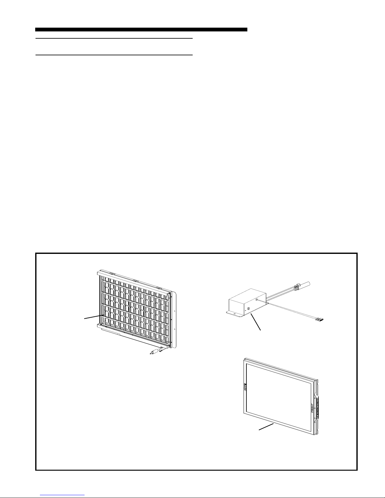
Figure 1. COMPONENTS OF THE INTEGRATED WHOLE HOUSE AIR CLEANER
1
Components of the integrated Whole House Air Cleaner:
1) FIELD CHARGER - Charges the contaminants
2) COLLECTION CELL - removes and collects very small
impurities from the air.
3) Power Supply - the solid state power supply converts
the 24 Volt AC to the high-voltage, direct current
required to power the FIELD CHARGER and COLLECTION CELL.
Check carefully for any shipping damage. This
must be reported to and claims made against the
transportation company immediately. Check to be
sure all major components are in the unit. Any
missing parts should be reported to your supplier
at once, and replaced with authorized parts only.
2
3
18-CD24D1-2 5
Installer’s Guide
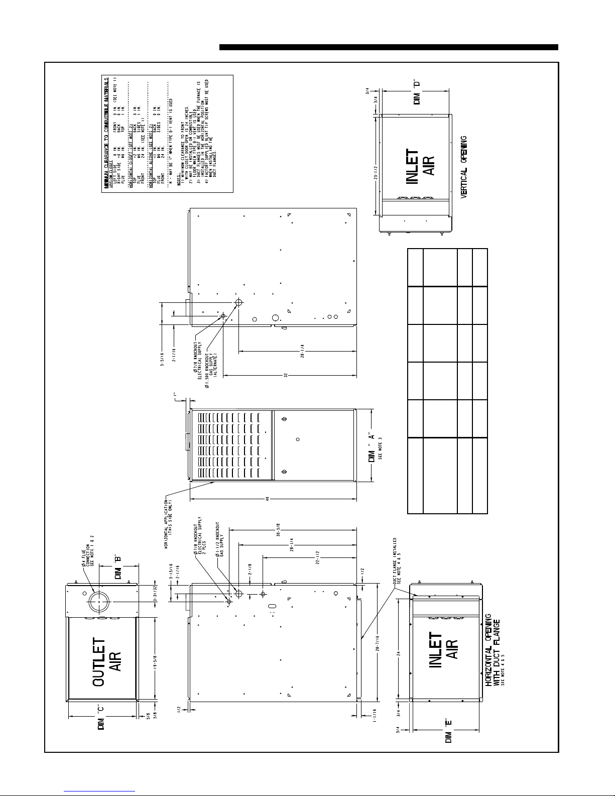
MODEL DIM "A" DIM "B" DIM "C" DIM "D" DIM "E"
*UD2B060AFV32A
*UD2B080AFV32A
*UD2B100AFV32A
17-1/2" 9-5/8" 16-1/4" 16" 16"
*UD2C080AFV42A 21" 13-1/16" 19-3/4" 19-1/2" 19-1/2"
*UD2D120AFV52A 24-1/2" 15-5/16" 23-1/4" 23" 23"
* PREFIX LETTER MAY BE "A" OR "T"
(ALL DIMENSIONS ARE IN INCHES)
*UD2 OUTLINE DRAWING
Bottom Return ONLY
6 18-CD24D1-2
INSTALLATION INSTRUCTIONS
▲
▲
!
CAUTION
Bottom panel for furnace to remain in place until unit
reaches final installation location. If bottom panel is removed before installation the collection cell and field
charger must also be removed to protect installation
personnel.
!
CAUTION
Remove the COLLECTION CELL and remove and discard the cardboard over the cell.
Installer’s Guide
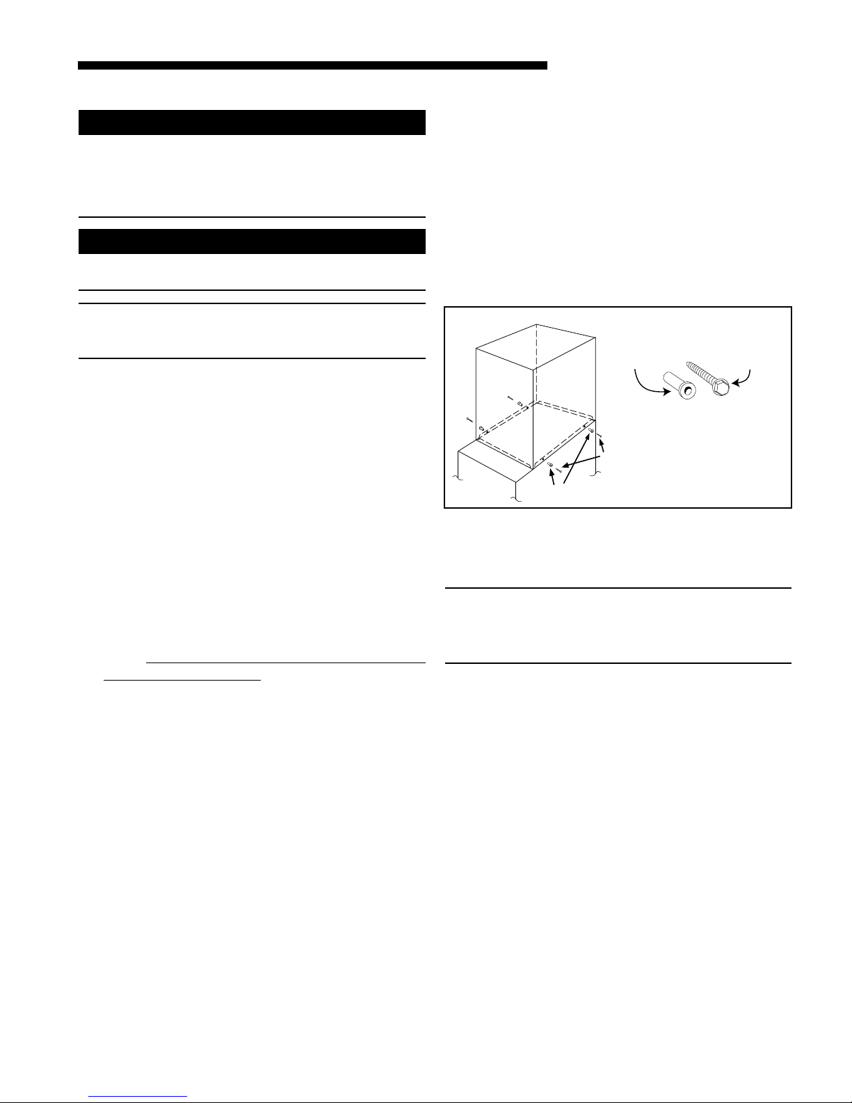
UPFLOW INSTALLATION
Standoffs and screws (See Figure 2) are included with
the cased coils for attachment to the Furnace. There
are clearance alignment holes near the bottom of the
coil wrapper. Drill screws are used to engage the Furnace top flanges. The standoff is inserted into the cabinet alignment hole. The drill screws are inserted
through the standoffs then screwed into the Furnace
flange. The coil is always placed downstream of the Furnace airflow. The above instructions apply only if the
coil is on top of an upflow Furnace.
NOTE: No sheetmetal screws may be used from 0-4"
from the bottom of the unit. Screws will interfere with
the Air Cleaner. See Figure 4.
REMOVING THE BOTTOM PLATE
a. Once the furnace is in place, remove the two screws
located at the front bottom corners of the Furnace.
b. Lean the furnace back slightly and remove the bot-
tom panel.
c. Replace the two screws removed in step a.
REMOVING THE COLLECTION CELL AND FIELD
CHARGER
When COLLECTION CELLS and FIELD CHARGER
must be removed, follow the steps below.
a. Remove the lower furnace door.
b. Remove the four screws holding the inner blower
panel and remove panel. Set aside in a safe place
until the unit is set in place and ready to start up.
c. Remove the COLLECTION CELL by sliding for-
ward.
Remove the cardboard from the COLLECTION CELL and discard. Set aside in a safe place
until the unit is set in place and ready to start up.
d. Disconnect the Green return wire and the Red high
voltage wire. Twist and pull the connector on the
Red wire to release.
e. Remove the two hold down screws on the bottom of
the FIELD CHARGER and retain.
f. Remove the Field Charger. Set aside in a safe
place until the unit is set in place and ready to start
up.
g. Set furnace in place. Repeat step a-g in reverse or-
der. Do Not put cardboard back in Furnace. Inner
blower door MUST be put back into place.
FOR VERTICAL
CASED
COIL
U
P
F
F
L
U
O
R
W
N
A
C
E
STANDOFFS
(BOTH SIDES)
STANDOFFS (4)
SCREWS
(BOTH SIDES)
DRILL SCREWS (4)
Figure 2
HORIZONTAL INSTALLATION
The coil and furnace must be fully supported when used
in the horizontal position.
IMPORTANT:
The 2/4TXC cased coil must be placed downstream of the
furnace. In horizontal installations, the apex of the coil
may point either toward or away from the furnace. See
the 2/4TXC coil Installer's Guide for more details.
The cased coil is secured to the Furnace and both the
Furnace and the cased coil must be properly supported.
The brackets mount using the rear screws on the coil
case and use the screws provided to secure the bracket
to the Furnace. The remaining bracket is placed as
close to center as possible (horizontally) between the
coil case front and the upflow Furnace, converted to
horizontal, aligns and attaches to the TXC coil. However, the coil requires additional support.
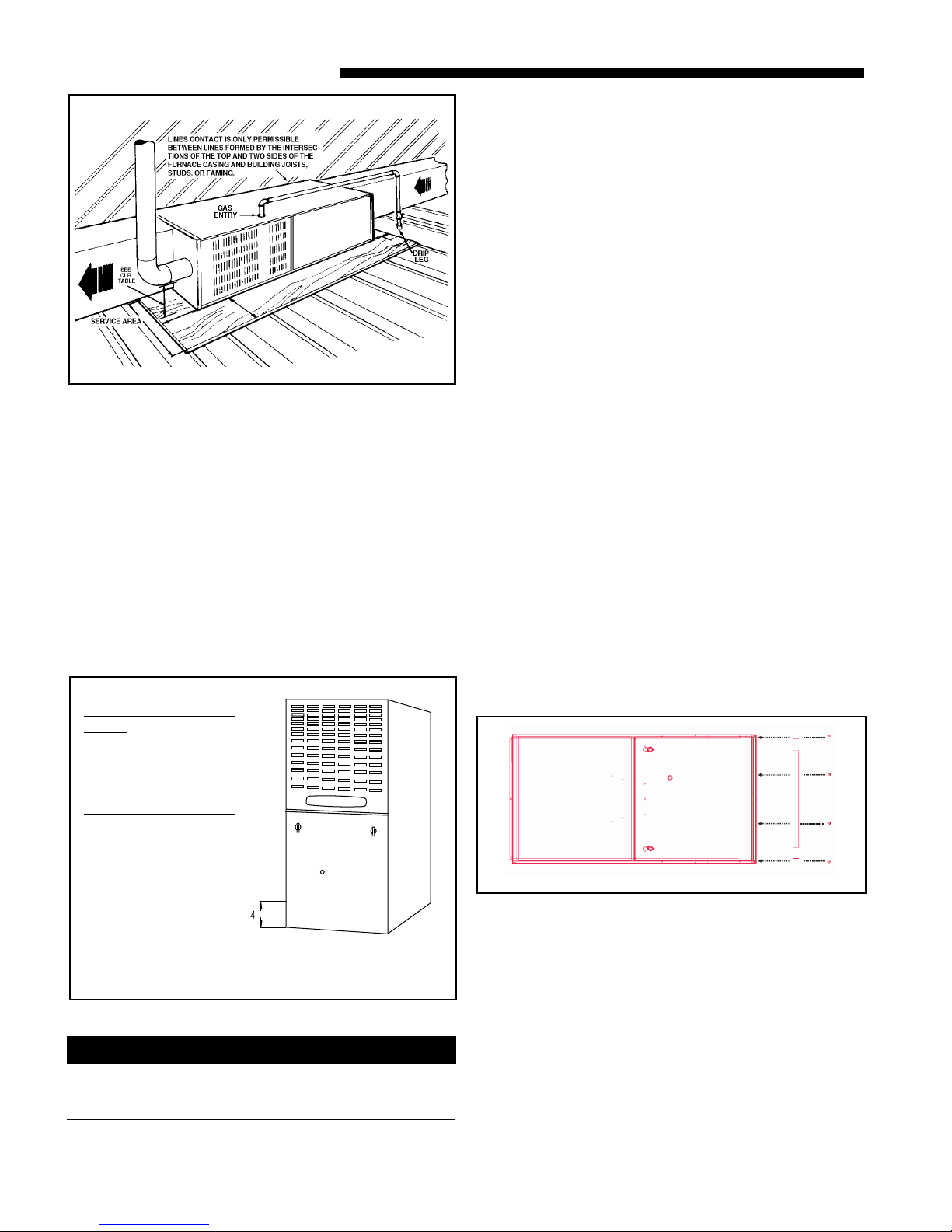
The horizontal Furnace installation in an attic should
be on a service platform large enough to allow for
proper clearances on all sides and service access to the
front of the Furnace (See Figure 3 & Clearance Table
1). Line contact is only permissible between lines
formed by intersections of the top and two sides of the
furnace casing and building joists, studs, or framing.
18-CD24D1-2 7
Installer’s Guide
▲
Typical Upflow/ Horizontal Attic Installation
1
Figure 3
The Furnace may be placed horizontally in a crawl space on a
pad or other noncombustible material which will raise the
unit for sufficient protection from moisture. The Furnace
must be supported at both ends and the middle when installed horizontally. The Furnace must also be elevated
approximately 4-6 inches to allow clearance for the condensate drain to exit the cabinet in the horizontal position.
The horizontal Furnace may also be suspended from the
joists using all-thread rods with a substantial metal support
frame that supports the entire length of the furnace. The rods
need to be of sufficient length to allow for proper clearances
from combustible materials. The frame needs to be at least
32" in length to allow for access to service panels.
If the Furnace is suspended using steel strap, it must be supported at all four corners and in the middle at the front of the
Furnace.
Materials
• Duct Flanges
Two 23.5" Flanges
Two Additional Flanges
15.92" (for 17.5" cabinet)
19.42" (for 21" cabinet)
21.92" (for 24.5" cabinet)
• Screws
Eight 5/16" Blunt Tip Screws with 5/16" Hex
Head
Steps
1. See Figures 5, 6, and 7 for flange orientation.
2. Attach flanges 1, 2, and 3 (Fig 7) to the unit using
the factory provided screws and the pre-drilled
holes in the wrapper. Flanges 1 and 2 are the
23.5" flanges that are generic to all units. Flange
3 will be one of two short flanges and the length
of which is dependent on the cabinet size.
3. Attach flange 4 (Fig 7) to the duct work (Flanges
should be inside duct work). Flange 4 is the
remaining short flange.
4. Place duct work with single flange over the 3
flanges that are currently attached to the unit
5. Attach duct work to remaining 3 flanges.
6. Attach the front flange from step 3 to the unit by
drilling 1/8" holes into the bottom channel. Use
the factory provided 5/16" blunt tip screws to
attach.
7. Use field supplied material to make an adequate
seal. DO NOT use silicon based sealant in
the airstream.
NOTE: No sheetmetal
screws may be used
from 0-4" from the
bottom of the unit.
Screws will interfere
with the air cleaner.
Figure 4
NOTE: Do NOT install screws to the bottom of the
unit except with Duct Flanges and Screws provided.
GUIDE FOR THE INSTALLATION OF DUCT FLANGES
Failure to use pre-drilled holes and the factory
provided screws can potentially damage air cleaner
components.
"
!
CAUTION
Figure 5: Horizontal Left
8 18-CD24D1-2

Installer’s Guide
Use pre-drilled
holes
1
4
Figure 6: Bottom View - Pre-drilled holes
1
4
2
Use predrilled
holes
3
2
Use predrilled
holes
3
AIR FOR COMBUSTION AND VENTILATION
Adequate flow of combustion and ventilating air must
not be obstructed from reaching the Furnace. Air openings provided in the Furnace casing must be kept free
of obstructions which restrict the flow of air. Airflow restrictions affect the efficiency and safe operation of the
Furnace. Keep this in mind should you choose to remodel or change the area which contains your Furnace.
Furnaces must have a free flow of air for proper performance.
Provisions for combustion and ventilation air shall be
made in accordance with “latest edition” of Section 5.3,
Air for Combustion and Ventilation, of the National
Fuel Gas Code, ANSI Z223.1, or Sections 7.2, 7.3 or 7.4
of CSA B149.1 Installation Codes, and applicable provisions of the local building codes. Special conditions created by mechanical exhausting of air and fireplaces
must be considered to avoid unsatisfactory Furnace operation.
Furnace locations may be in “confined space” or “unconfined space”. Unconfined space is defined in Table 2 and
Figure 8. These spaces may have adequate air by infiltration to provide air for combustion, ventilation, and
dilution of flue gases. Buildings with tight construction
(for example, weather stripping, heavily insulated,
caulked, vapor barrier, etc.), may need additional air
provided as described for confined space.
Figure 7: Bottom View Flange Attachment
Tab le 1
Minimum Clearance to Combustible Materials
Upflow Closet
Left Side 0 inches Front 3 inches (note 1)
Right Side 0 inches Back 0 inches
Flue 6 inches * Top 1 inch
Horizontal Closet
(see note 2)
Top 2 inches Back 3 inches
Flue 6 inches * Sides 1 inch
Front 18 inches (note 1)
Horizontal Alcove
(see note 2)
Top 1 inch Back 0 inches
Flue 6 inches Sides 0 inches
Front 18 inches
* May be 1" when type B-1 vent is used
NOTES:
1) Minumum clearance to front on *UD2D120 is 6 inches
2) May be installed on combustible floor when type B-1 vent is used.
UNCONFINED
50 CU. FT. OR MORE
PER 1000 BTU/ HR. INPUT
ALL EQUIP. INSTALLED
Figure 8
TABLE 2
MINIMUM AREA IN SQUARE FEET
FOR UNCONFINED SPACE INSTALLATIONS
FURNACE
MAXIMUM BTUH
INPUT RATING
60,000
80,000
100,000
120,000
140,000
WITH 8 FT. CEILING
MINIMUM AREA IN SQUARE
FEET OF UNCONFINED SPACE
375
500
625
750
875
1. All air from inside the building as in Figure 10: The
confined space shall be provided with two permanent openings communicating directly with an additional room(s) of sufficient volume so that the combined volume of all spaces meets the criteria for an
unconfined space. The total input of all gas utilization equipment installed in the combined space
shall be considered in making this determination.
Refer to Table 3, for minimum open areas required.
18-CD24D1-2 9
 Loading...