

American Standard TMM4A0A18S21SA, TMM4A0A24S21SA, TMM4A0B30S21SA, TMM4A0B36S31SA Installer's Manual
WALL-MOUNT AIR HANDLERS
1.5-3TON COOLING
ALL phases of this installation must comply with NATIONAL, STATE AND LOCAL CODES
Important: This Document is customer property and is to remain with this unit.
Installer’s Guide
Section 1. Features
1.1 Standard Features
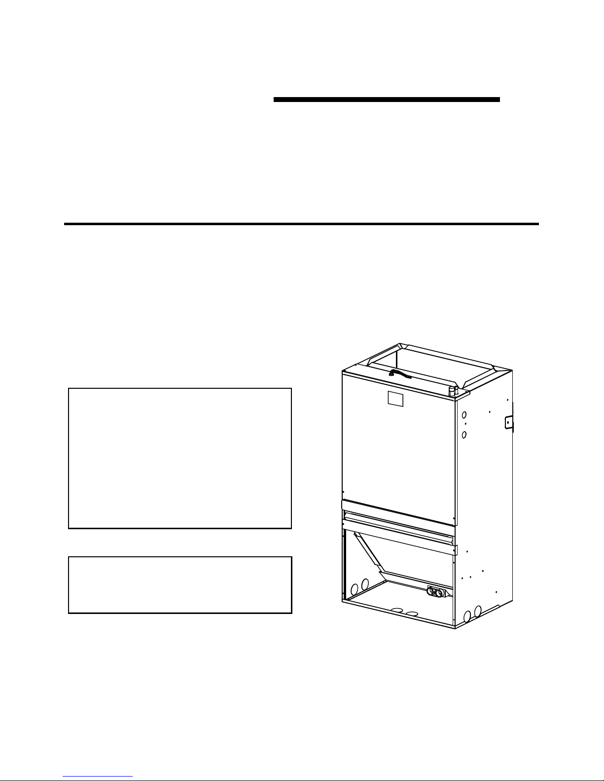
The TMM4A series wall mount air handler is designed for installation in a closet, utility room, alcove
and can be wall mounted. These versatile units are applicable to air conditioning applications. Field
installed electric resistance heaters are available.
18-GF07D1-1
• FRONT OR BOTTOM RETURN AIR.
• PAINTED FINISH ON GALVANIZED STEEL
• STURDY POLYCARBONATE DRAIN PANS
- The TMM4A wall mount air handler has factory
installed drain pans and is shipped for upflow
applications only.
•
208/230 VAC OPERATION
1.2 Optional Accessories
• 5, 7.5 and 10 kW SINGLE PHASE ELECTRIC
HEATERS
- Circuit breakers are standard on all single
phase 5, 7.5 and 10 kW heaters.
•
STUD OR WALL MOUNTING TABS
•
FULLY INSULATED CABINET
•
3/4'' NPT PRIMARY AND SECONDARY DRAINS
TMM4A0A18S21SA
TMM4A0A24S21SA
TMM4A0B30S21SA
TMM4A0B36S31SA
2
SAFETY HAZARD! This information is intended for use by
individuals possessing adequate backgrounds of electrical
and mechanical experience. Any attempt to repair a central air
conditioning product may result in personal injury and/or
property damage. The m anufacturer or seller cannot be
responsible for the interpretation of this information, nor can it
assume any liability in connection with its use.
Important: These instructions do not cover all variations in systems
nor provide for every possible contingency to be met in connection
with the installation. Should further information be desired or should
particular problems arise which are not covered sufficiently for the
purchaser ’s purposes, the m atter should be referred to your
installing dealer or local distributor.
Note: The manufacturer recommends installing ONLY A.H.R.I.
approved, matched indoor and outdoor systems. Some of the
benefits of installing approved matched indoor and outdoor split
systems are maximum efficiency, optimum performance, and the
best overall system reliability.
Important: Installation of this unit shall be made in accordance with
the National Electric Code, NFPA No. 90A and 90B, and any other
local codes or utilities requirements.
Note: The small air handlers have been evaluated in accordance
with the Code of Federal Regulations, Chapter XX, Part 3280 or the
equivalent. “SUITABLE FOR MOBILE HOME USE.”
WARNING
WARNING
WARNING
WARNING
WARNING
WARNING
HAZARDOUS VOLTAGE!
Disconnect all electrical power, including remote disconnects
before installing or servicing. Follow proper lockout/tagout
procedures to ensure the power can not be inadvertently
energized. Failure to disconnect power before servicing could
result in death or serious injury.
CAUTION
CORROSION HAZARD! To prevent shortening its service life,
the air handler should not be used during the finishing phases
of construction. The low return air temperatures can lead to
the formation of condensate. Condensate in the presence of
chlorides and fluorides from paint, varnish, stains, adhesives,
cleaning compounds , and cement creates a corrosive
condition which may cause rapid deterioration of the cabinet
and internal components.
CAUTION
SAFETY HAZARD! Sharp Edge Hazard. Be careful of sharp
edges on equipment or any cuts made on sheet metal while
installing or servicing. Personal injury may result.
LIVE ELECTRICAL COMPONENTS! During installation,
testing, servicing, and troubleshooting of this product, it may
be necessary to work with live electrical components. Failure
to follow all electrical safety precautions when exposed to live
electrical components could result in death or serious injury.
EXPLOSION HAZARD!
Do not store corrosive or combustible materials, gasoline, or
other flammable vapors or liquids near the unit. Failure to
follow this warning could result in property damage, serious
personal injury, or death.
ELECTRICAL HAZARD!
Grounding Required! Follow proper local and state electrical
code on requirements for grounding. Failure to follow this
warning could result in property damage, serious personal
injury, or death.
HAZARDOUS VAPORS! Do not install an air handler with a
non-ducted return in the same closet, alcove, or utility room
as a fossil fuel device. Hazardous vapors can be distributed
throughout the conditioned space and equipment damage can
result.
WARNING
THIS PRODUCT CONTAINS FIBERGLASS WOOL
INSULATION! FIBERGLASS DUST AND CERAMIC FIBERS
ARE BELIEVED BY THE STATE OF CALIFORNIA TO
CAUSE CANCER THROUGH INHALATION. GLASSWOOL
FIBERS MAY ALSO CAUSE RESPIRATORY, SKIN, OR EYE
IRRITATION.
PRECAUTIONARY MEASURES
• Avoid breathing fiberglass dust
• Use a NIOSH approved dust/mist respirator
• Avoid contact with the skin or eyes. Wear long-sleeved,
loose fitting clothing, gloves, and eye protection.
• Wash clothes separately from other clothing, rinse washer
thoroughly.
• Operations, such as sawing, blowing, tear-out, and spraying
may generate fiber concentrations requiring ad ditional
respiratory protection. Use the appropriate NIOSH approved
respirator in these situations.
FIRST AID MEASURES
EYE CONTACT: FLUSH EYES WITH WATER TO REMOVE DUST
IF SYMPTOMS PERSIST, SEEK MEDICAL ATTENTION.
SKIN CONTACT: WASH AFFECTED AREA GENTLY WITH SOAP
AND WARM WATER AFTER HANDLING.
Section 2. Safety Information
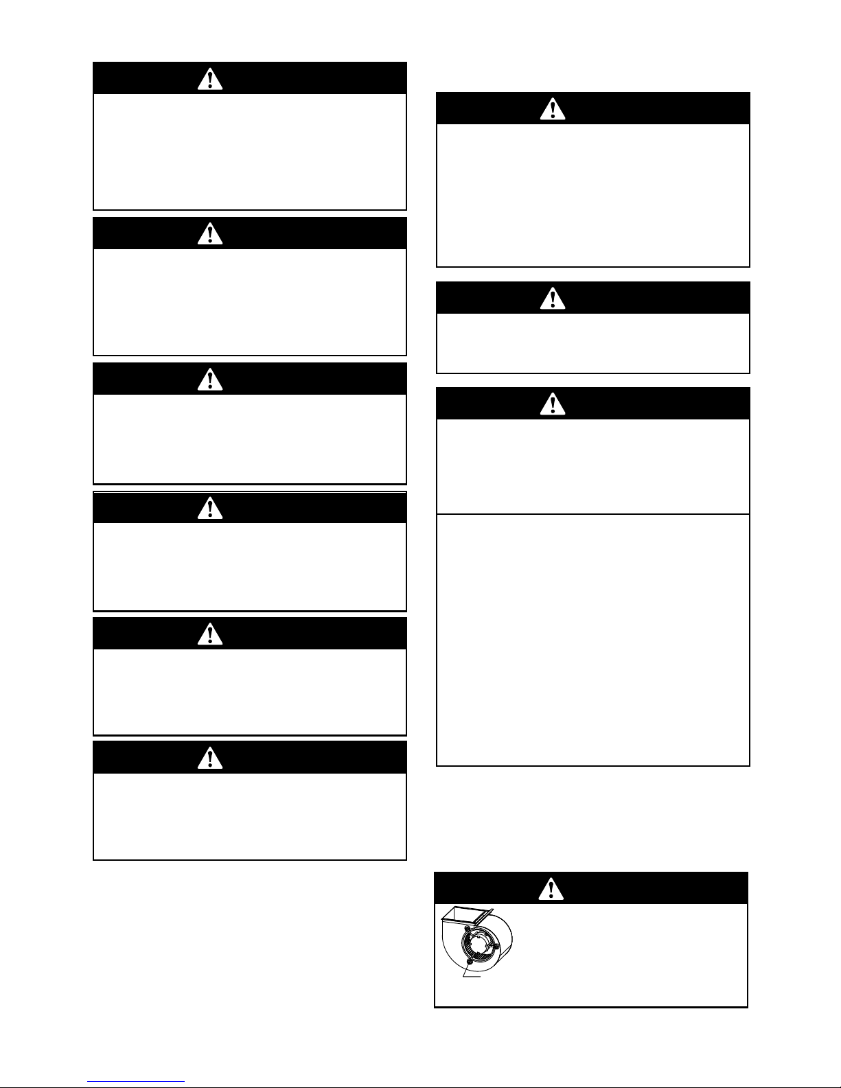
WARNING
Make sure the blower motor support is tight
(3-motor mount bolts) then check to see if
wheel is secured to motor shaft before
operating unit.
BLOWER MOTOR
SHIPPING BOLT
3
Carefully unpack the unit and inspect the contents for damage. If
any damage is found at the time of delivery, proper notification and
claims should be made with the carrier.
Check the rating plate to assure model number and voltage, plus
any kits match with what you ordered. The manufacturer should be
notified within 5 days of any discrepancy or parts shortage.
The small air handler should be centrally located and may be
installed in a closet, alco ve, utility room , basement. Minimum
clearances must be met.
The air handler comes standard with two different options for
mounting, wall mount or frame mount. Both mounting options require
the unit to be level from side to side and from front to back in order to
allow condensate to properly drain from the unit. Failure to do this will
result in condensate to leak out from the unit potentially causing
structural damage to the surrounding support structures, dry wall,
carpet, etc. around the unit. Also, both mounting structures require
the ability to accommodate a minimum of 150 lb load. Failure to do
this will cause damage to the support structure and potentially
damage the unit.
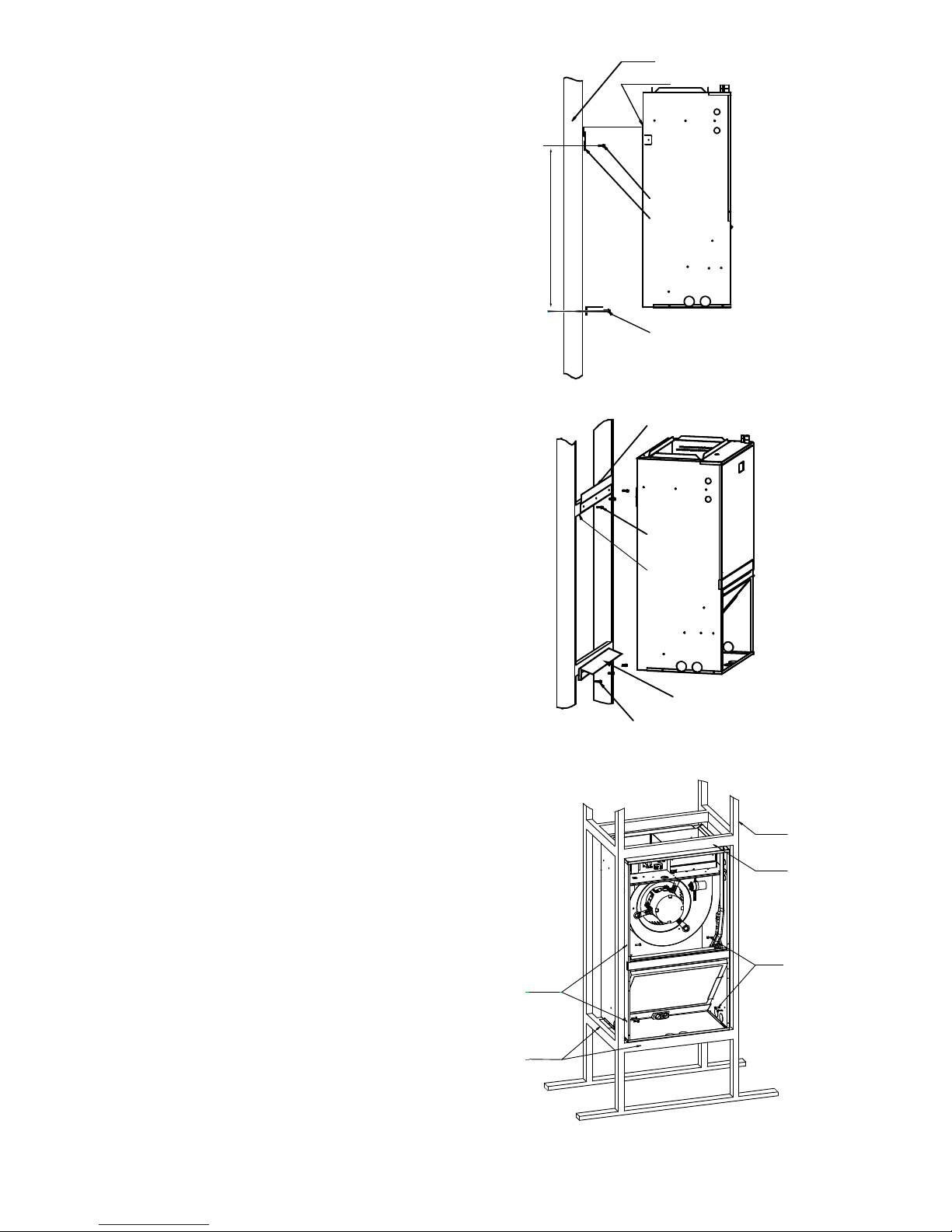
The air handler comes standard with an upper and lower wall mount
bracket. Reference Figure 3-1 for more detail.
1. Remove lower wall mounting bracket from the back of the unit by
removing one screw which attaches the bracket to the air handler.
Note: Discard the screw after you have removed the wall mounting
bracket.
2. Install bracket on the wall by using 3 wood screws (not provided).
Make sure the bracket is level in order to provided proper drainage
from the unit. Note: Do not attach the wall mounting bracket into
unsupported dry wall. Make sure that the wood screws are going into
a structure that can suppport a minimum of 150 lb load.
3. Lift the air handler above the wall mounting bracket and attached
the unit to the installed bracket. Reference Figure 3-1.
4. Install the additional bottom plate for extra support for this type
mounting (see figure 3-1).
Note: The additional plate is shipped in the bottom of the shipping
carton (only for 30/36k unit).
3.2.1 WALL MOUNT
Fig. 3-2 FRAME MOUNT
The air handler comes with 8 clearance holes 4 on each side. These
holes are used to mount the air handler inside of a frame structure
(see Figure 3-2). When mounting in this fashion, make sure that the
wood screws are mounted from within the air handler and not outside
of the unit. Installing the screws from the outside of the unit, And
notice don’t damage to the coil.
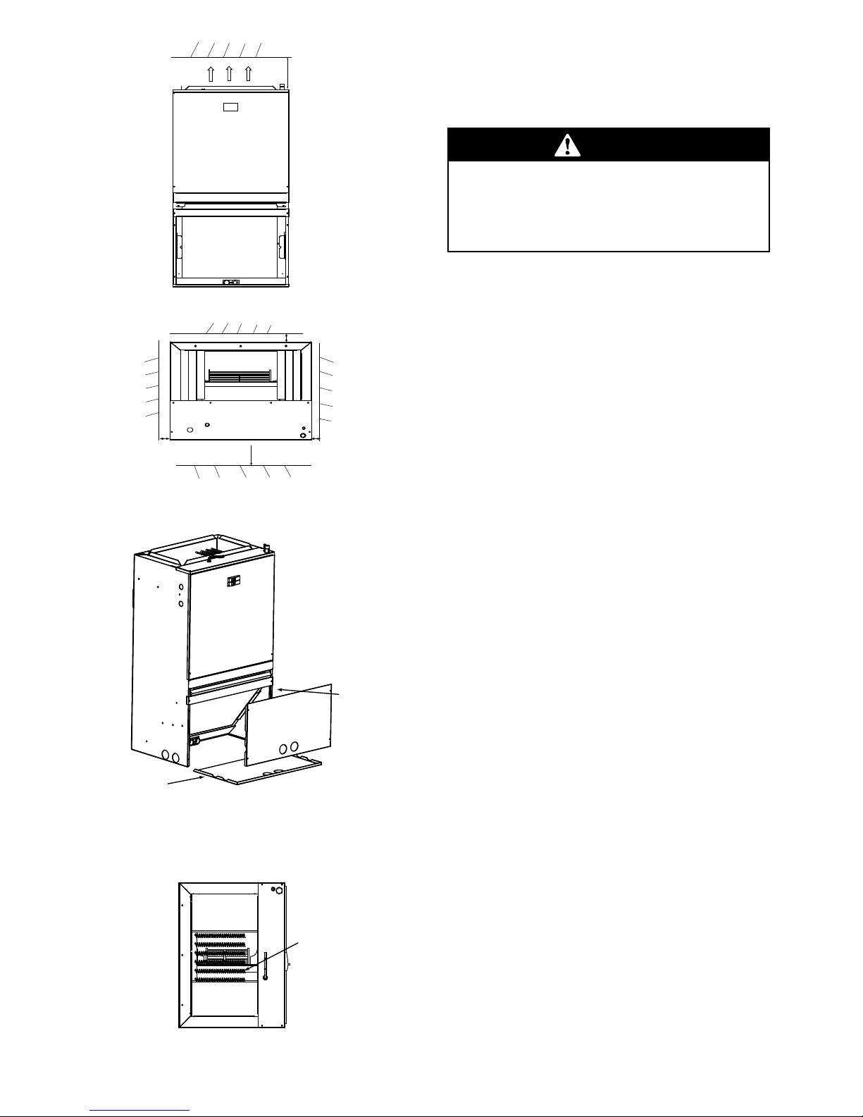
For ensure the proper installation for frame mount, Select the enough
solid and level site. Ensure enough space required for installation and
maintenance(See Figure. 3-3)
3.2.2 FRAME MOUNT
PROVIDED WALL
MOUNT BRACKET
WALL MOUNT PLATE
WOOD SCREWS
SUPPORTING 2˝X4˝
STRUCTURE
WALL STRUCTURE
WOOD SCREWS
WOOD SCREWS
PROVIDED WALL
MOUNT BRACKET
NOTE: MOUNTING WALL AND SUPPORTING
STRUCTURE MUST BE ABLE TO SUPPORT A
MINIMUM OF 150 LBS.
PROVIDED AIR HANDLER
MOUNTING BRACKET
Fig. 3-1 WALL MOUNT
WOOD SCREWS
31.5˝
Section 3. Installation Instructions
3.1 Unpacking
3.2 Location
WALL STRUCTURE
SUPPORTING
2"X4" STRUCTURE
WOOD SCREWS
SUPPORTING
2"X4" STRUCTURE
STUD ATTACHMANT
HOLES
4
REMOVE BOTTOM COIL
PANEL OFF PLATE
INSTALL FRONT
COIL PANEL
Fig. 3-4 DIFFERENT AIR SUPPLY
3.2.3 CONFIGURATIONS
Fig.3-3 Space for frame mount
≥0"
Fig. 3-5 HEATER ELEMENTS INSTALLATION
ELECTRIC HEATER KITS
Bottom Return Conversion: Divert the return air from the factory
standard front return to a bottom return.Remove the cross brace
when converting cabinet to bottom return.
3.3 Duct Work
3.4 Condensate Drain
Field ductwork must comply with the National Fire Protection
Association NFPA 90A, NFPA 90B an d any applicable local
ordinance.
WARNING
Do not, under any circumstances, connect return ductwork to any
other heat producing device such as fireplace insert, stove, etc.
Unauthorized use of such devices may result in fire, carbon
monoxide poisoning, explosion, personal injury or property
damage.
Sheet metal ductwork run in unconditioned spaces must be insulated
and covered with a vapor barrier. Fibrous ductwork may be used if
constructed and installed in accordance with SMACNA Construction
Standa rd on Fibrous Glass Ducts. Ductwork must comply with
National Fire Protection Association as tested by U/L Standard 181
for Class I Air Ducts. Check local codes for requirements on
ductwork and insulation.
• Duct system must be designed within the range of external static
pressure the unit is designed to operate against. It is important that
the system airflow be adequate. Make sur e supply and return
ductwork, grills, special filters, accessories, etc. are accounted for in
total resistance. See airflow performance tables in this manual.
• Design the duct system in accordance with “ACCA” Manual “D”
Design for Residential Winter and Summer Air Conditioning and
Equipment Selection. Latest editions are available from: “ACCA” Air
Conditioning Contractors of America, 1513 16th Street, N.W.,
Washington, D.C. 20036. If duct system incorporates flexible air
duct, be sure pressure drop Information (straight length plus all
turns) shown in “ACCA” Manual “D” is accounted for in system.
• Supply plenum is attached to the 3/4” duct flanges supplied with
the unit.
IMPORTANT: If an elbow is included in the plenum close to the unit,
it must not be smaller than the dimensions of the supply duct flange
on the unit.
• IMPORTANT: The front flange on the return duct if connected to
the blower casing must not be screwed into the area where the
power wiring is located. Drills or sharp screw points can damage
insulation on wires located inside unit.
The unit is supplied with primary and auxiliary condensate drains
that have 3/4” NPT connections. Both drains must be trapped
outside the unit and piped in accordance with applicable building
codes. Do not reduce the drain line size less than the connection
size on the drain pan. Condensate should be piped to an open drain
or to the outside. All drains must pitch downward away from the unit
a minimum of 1/4” per foot of line to ensure proper drainage.
Insulate the primary drain line to prevent sweating where dew point
temperatures may be met. (Insulation is optional depending on
climate and application needs.)
• Secure the supply and return ductwork to the unit flanges, using
proper fasteners for the type of duct used and tape the duct-to-unit
joint as required to prevent air leaks.
Important: If cleanout Tee is used, standpipe must be sealed/capped.
Top view of the indoor unit clearance(including air duct).
》20"
≥0"
≥24"
≥0"
Front of unit
AIRFLOW
 Loading...