

American Standard AFD145ALFR, TFD175ALFR, TFD145ALFR, AFD175ALFR, AFD210ALFR Service Manual
...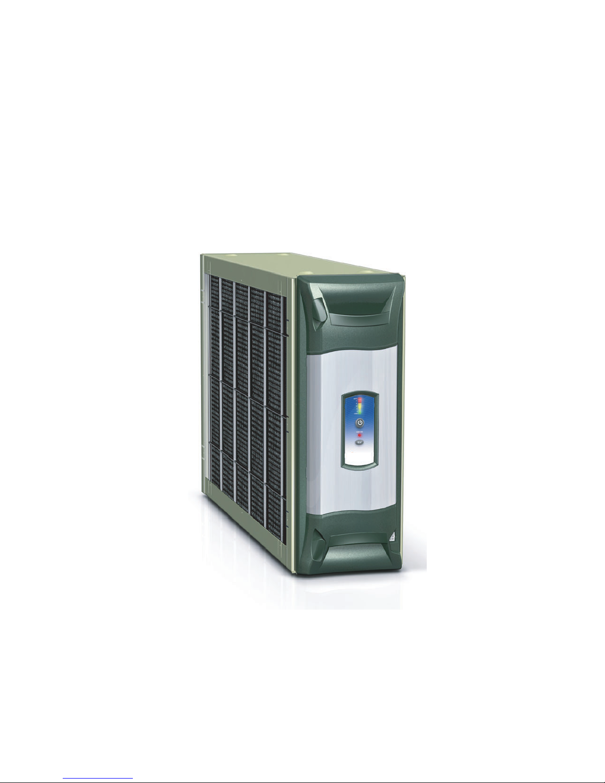
IFD AIR CLEANER SERVICE MANUAL
PUB NO. 34-3446-01
Service Manual
44
4
44
1
33
3
33
11
1
11
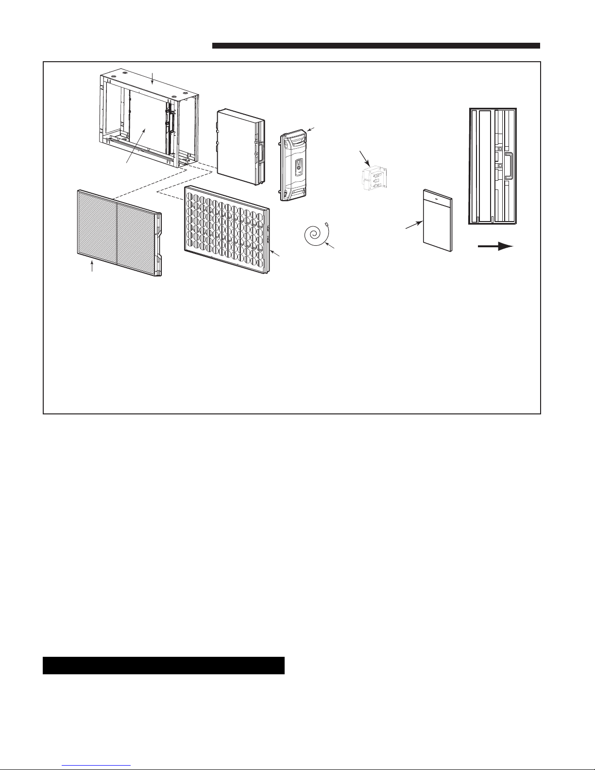
COMPONENTS OF THE AIR CLEANER
55
5
55
66
6
77
7
77
66
88
8
88
33
3
33
22
2
22
11
1
11
22
2
22
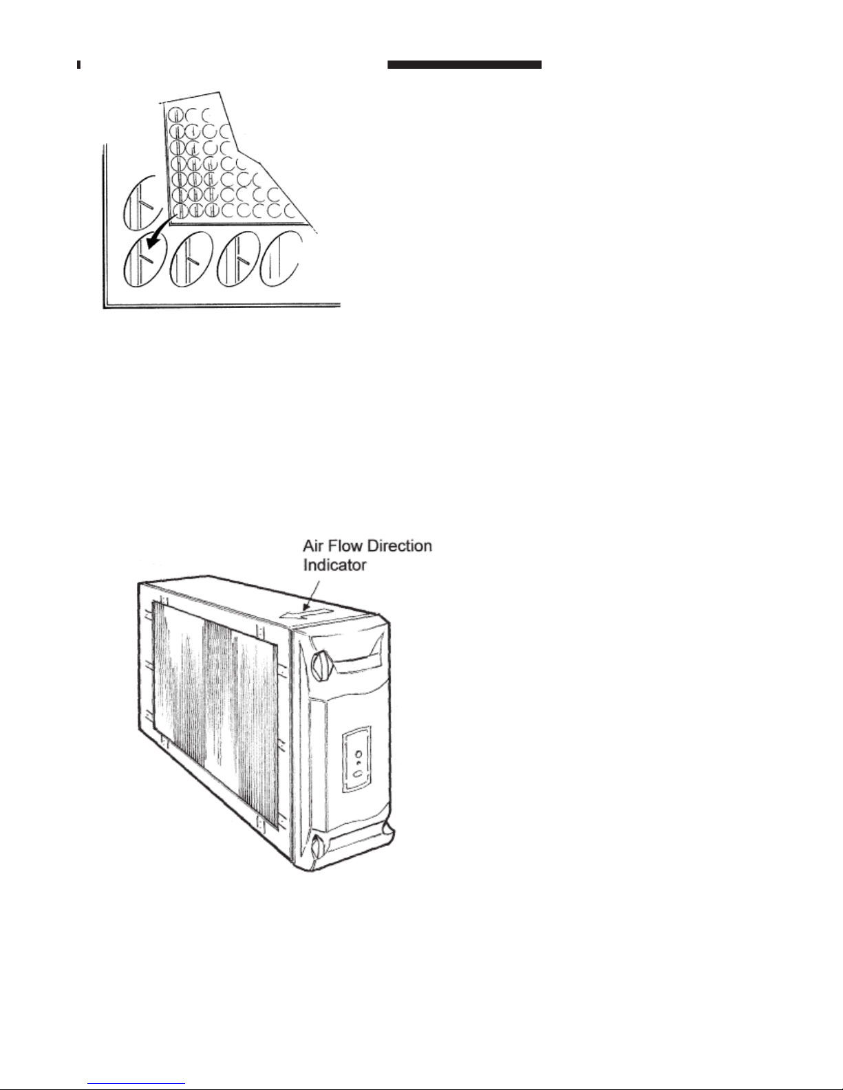
AIR
FLOW
33
3
33
1) Pre-filter - traps large particles such as hair and lint before
they can enter the cell section.
2) Field Charger - Charges the contaminants
3) Collector Cell (2) - removes and collects small impurities
from the air.
4) Cabinet - mounts between the furnace/air handler and
return air duct work and houses the collector cells, field
charger and pre-filter.
5) Power Door - the solid state power supply components
that convert the 24 Volt AC to the high-voltage, direct
current required to power the field charger and cells. Allows
access to the fluted collector cells, field charger and prefilter.
6) Transformer - supplies 24 Volts to the indoor unit and air
cleaner
7) 24 Volt Power / Control Cable
8) Gasket, Literature and Hardware Packet
THEORY OF OPERATION
Air in the home is circulated through the heating and cooling system, maintaining the temperature at a comfortable
level. At the same time, the circulated return air is passing through the indoor equipment millions of small air-born
particles such as smoke and pollen, most of them are to small to be visible, are carried by the returning air to the
Electronic Air Cleaner. The reasons this Electronic Air Cleaner efficiency is so superior to previous models is the new
design of the ionizing section call the field charger section and the radical departure from charged metal collector
plates to charged insulated collector cells. The air-born particles in the return air pass through the field charger section
where the positive high voltage ionizer pins are located. The positive high voltage on the field charger pins will cause
the air-born particles passing by them to become positively charged. The collector cells surfaces are insulated from the
high voltage, which will reduce electrical arcing noise. These charged collector cells attract and hold the positively
charged air-born particles to their negative insulated charged surfaces. An electrostatic electronic air cleaner makes
use of the basic law of attraction, opposite charges attract.
!
WARNING
▲
RISK OF ELECTRIC SHOCK: These servicing instructions
are for use by qualified personnel only. To reduce the risk of
electric shock, do not perform any servicing other than that
contained in these operating instructions unless you are
qualified to do so.
© 2005 American Standard Inc. All Rights Reserved SF
Service Manual
FIELD CHARGER IONIZER PINS ARE POSITIVE CHARGED.
AT THE NORMAL POWER SETTING THE IONIZER PINS WILL HAVE
9,600 VOLTS DC APPLIED TO THEM.
THE POWER SETTING CAN BE CHANGED IN THE SET UP MODE OF
OPERATION.
COLLECTOR CELLS ARE INSULATED CELLS WITH ONE SIDE OF THE
CELL POSITIVELY CHARGED AND THE OTHER SIDE OF THE CELL
NEGATIVELY CHARGED. A POSITIVELY CHARGED AIRBORNE
PARTICLE WILL BE ATTRACTED AND HELD IN PLACE TO THE
NEGATIVELY CHARGED AREA OF THE COLLECTOR CELL.
SF 3
Service Manual
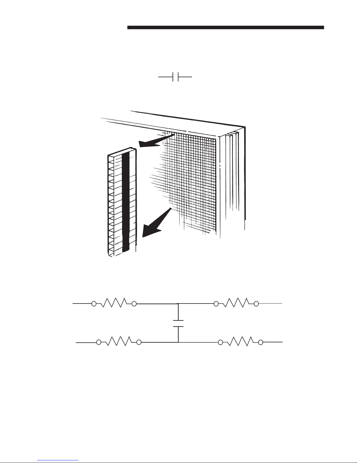
COLLECTOR CELL CONSTRUCTION
Collector cells start out as a strip of corrugated box plastic strips. On the top and bottom of the strip a conductive
ink strip is applied. These inked plastic strips are then glued together, one on top of the other forming the collector
cells. Electrically the cell is now a capacitor.
Capacitor Symbol
10 meg ohm resistors are placed in each leg of the cell to limit high current surges.
10 Meg Ohms
OUTPUT
Cell Strips
10 Meg Ohms
The standard Digital Ohm Meter will not read over 10 meg Ohms. The total resistance from the Collector High
Voltage input terminal to it’s High Voltage output terminal is 20 Meg Ohms.
10 Meg Ohms
INPUT
10 Meg Ohms
4 SF
Service Manual
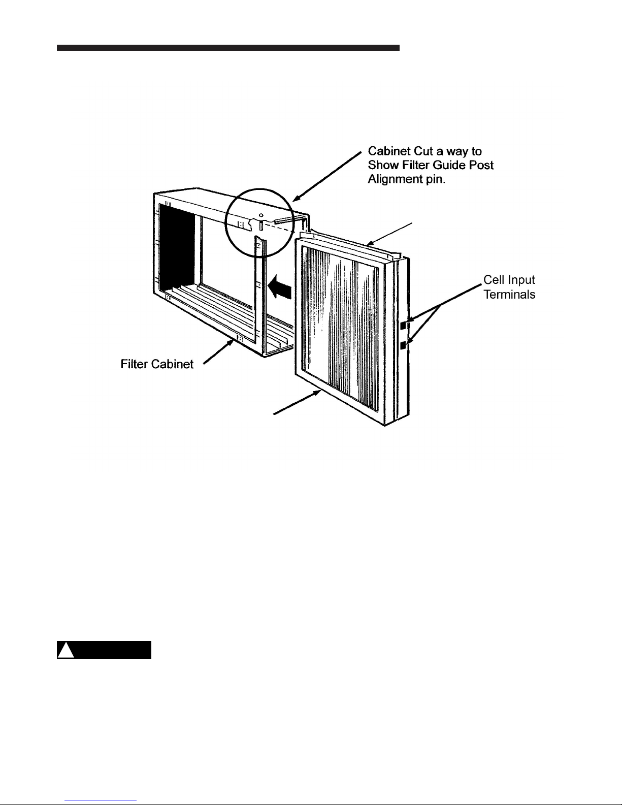
Collector Cell Guide Strips
Collector Cell
CAUTION
!
Do Not expose filter to UV light. UV light can cause plastic
material to deteriorate which may lead to filter damage
SF 5
 Loading...