

American Standard TUY060R9V3W, AUY120R9V5W, AUY080R9V3W, TUY100R9V4W, TUY120R9V5W Service Facts
...
Service Facts
Gas Furnace – Var. Speed Blower –
Var. Speed Inducer – Two Stage Heat –
X341119P12
Direct Vent
Models: * - First letter may be “A” or “T”
*UY060R9V3W *DY060R9V3W
*UY080R9V3W *DY080R9V3W
*UY100R9V4W *DY100R9V4W
*UY120R9V5W *DY120R9V5W
IMPORTANT — This document contains a wiring diagram and service information. This is customer property and is to
MODEL
TYPE
RATINGS 2
1st Stage Input BTUH
1st Stage Capacity BTUH (ICS)
2nd Stage Input BTUH
2nd Stage Capacity BTUH (ICS)
Temp. rise (Min.-Max.) °F.
BLOWER DRIVE
Diameter - Width (In.)
No. Used
Speeds (No.)
CFM vs. in. w.g.
Motor HP
R.P.M.
Volts / Ph / Hz
COMBUSTION FAN - Type
Drive - No. Speeds
Motor HP - RPM
Volts / Ph / Hz
FLA
FILTER — Furnished?
Type Recommended
Hi Vel. (No.-Size-Thk.)
VENT — Size (in.)
HEAT EXCHANGER
Type -Fired
-Unfired
Gauge (Fired)
ORIFICES — Main
Nat. Gas. Qty. — Drill Size
L.P. Gas Qty. — Drill Size
GAS VALVE
PILOT SAFETY DEVICE
Type
BURNERS — Type
Number
POWER CONN. — V /Ph / Hz 4
Ampacity (In Amps)
Max. Overcurrent Protection (Amps)
PIPE CONN. SIZE (IN.)
DIMENSIONS
Crated (In.)
WEIGHT
Shipping (Lbs.) / Net (Lbs)
1 Central Furnace heating designs are certified by AGA and CSA.
2 For U.S. applications, above input ratings (BTUH) are up to 2,000 feet, derate 4% per 1,000 feet for elevations above 2,000 feet above sea level.
For Canadian applications, above input ratings (BTUH) are up to 4,500 feet, derate 4% per 1,000 feet for elevations above 4,500 feet above sea level.
3 Based on U.S. government standard tests.
4 The above wiring specifications are in accordance with National Electrical Code; however, installations must comply with local codes.
remain with this unit. Please return to service information pack upon completion of work.
WARNING
*UY060R9V3W
Upflow / Horizontal
39,000
3
3
37,000
60,000
56,000
35 - 65
DIRECT
10 x 8
Variable
See Fan Performance Table
1/2
Variable
115/1/60
Centrifugal
Direct - Variable
1/50 - 5000
33 - 110/3/60 - 180
1.0
Yes
High Velocity
1 - 17x25 - 1 in.
2 Round
Aluminized Steel - Type I
3 — 45
3 — 56
Redundant - Two Stage
Hot Surface Igniter
Multiport Inshot
115/1/60
11.1
1/2
H x W x D
41-3/4 x 19-1/2 x 30-1/2
158 / 146
DISCONNECT POWER BEFORE SERVICING
PRODUCT SPECIFICATIONS
*UY080R9V3W
Upflow / Horizontal
52,000
48,000
80,000
73,000
35 - 65
DIRECT
10 x 8
1
See Fan Performance Table
20
3
15
1
Variable
1/2
Variable
115/1/60
Centrifugal
Direct - Variable
1/50 - 5000
33 - 110/3/60 - 180
1.0
Yes
High Velocity
1 - 17x25 - 1 in.
2 Round
Aluminized Steel - Type I
20
4 — 45
4 — 56
Redundant - Two Stage
Hot Surface Igniter
Multiport Inshot
4
115/1/60
11.1
15
1/2
H x W x D
41-3/4 x 19-1/2 x 30-1/2
168 / 156
1
*UY100R9V4W
Upflow / Horizontal
65,000
60,000
100,000
93,000
35 - 65
DIRECT
10 x 10
1
Variable
See Fan Performance Table
1
Variable
115/1/60
Centrifugal
Direct - Variable
1/50 - 5000
33 - 110/3/60 - 180
1.0
Yes
High Velocity
1 - 20x25 - 1 in.
3 Round
Aluminized Steel - Type I
20
5 — 45
5 — 56
Redundant - Two Stage
Hot Surface Igniter
Multiport Inshot
5
115/1/60
13.5
20
1/2
H x W x D
41-3/4 x 23 x 30-1/2
197 / 185
*UY120R9V5W
Upflow / Horizontal
78,000
72,000
120,000
112,000
40 - 70
DIRECT
10 x 10
1
Variable
See Fan Performance Table
1
Variable
115/1/60
Centrifugal
Direct - Variable
1/50 - 5000
33 - 110/3/60 - 180
1.0
Yes
High Velocity
1 - 24x25 - 1 in.
3 Round
Aluminized Steel - Type I
20
6 — 45
6 — 56
Redundant - Two Stage
Hot Surface Igniter
Multiport Inshot
6
115/1/60
15.2
20
1/2
H x W x D
41-3/4 x 26-1/2 x 30-1/2
206 / 193
B - FURNACES
NOTICE: Since the manufacturer has a policy of continuous product and product data improvement,
it reserves the right to change design and specifications without notice.
© 2005 American Standard Inc. All Rights Reserved
Page B-651-438
W.M. 1/05R

Service Facts
PRODUCT SPECIFICA TIONS
MODEL
TYPE
RATINGS 2
1st Stage Input BTUH
1st Stage Capacity BTUH (ICS)
2nd Stage Input BTUH
2nd Stage Capacity BTUH (ICS)
Temp. rise (Min.-Max.) °F.
BLOWER DRIVE
Diameter - Width (In.)
No. Used
Speeds (No.)
CFM vs. in. w.g.
Motor HP
R.P.M.
Volts / Ph / Hz
COMBUSTION FAN - Type
Drive - No. Speeds
Motor HP - RPM
Volts / Ph / Hz
FLA
FILTER — Furnished?
Type Recommended
Hi Vel. (No.-Size-Thk.)
VENT — Size (in.)
HEAT EXCHANGER
Type -Fired
-Unfired
Gauge (Fired)
ORIFICES — Main
Nat. Gas. Qty. — Drill Size
L.P. Gas Qty. — Drill Size
GAS VALVE
PILOT SAFETY DEVICE
Type
BURNERS — Type
Number
POWER CONN. — V / Ph / Hz 4
Ampacity (In Amps)
Max. Overcurrent Protection (Amps)
PIPE CONN. SIZE (IN.)
DIMENSIONS
Crated (In.)
WEIGHT
Shipping (Lbs.) / Net (Lbs)
1 Central Furnace heating designs are certified by AGA and CSA.
2 For U.S. applications, above input ratings (BTUH) are up to 2,000 feet, derate 4% per 1,000 feet for elevations above 2,000 feet above sea level.
For Canadian applications, above input ratings (BTUH) are up to 4,500 feet, derate 4% per 1,000 feet for elevations above 4,500 feet above sea level.
3 Based on U.S. government standard tests.
4 The above wiring specifications are in accordance with National Electrical Code; however, installations must comply with local codes.
3
3
*DY060R9V3W
Downflow / Horizontal
39,000
36,000
60,000
56,000
35 - 65
DIRECT
10 x 8
1
Variable
See Fan Performance Table
1/2
Variable
115/1/60
Centrifugal
Direct - Variable
1/50 - 5000
33 - 110/3/60 - 180
1.0
Yes
High Velocity
2 - 14x20 - 1 in.
2 Round
Aluminized Steel - Type I
20
3 — 45
3 — 56
Redundant - Two Stage
Hot Surface Igniter
Multiport Inshot
3
115/1/60
11.1
15
1/2
H x W x D
41-3/4 x 19-1/2 x 30-1/2
160/ 146
*DY080R9V3W
Downflow / Horizontal
52,000
48,000
80,000
74,000
35 - 65
DIRECT
10 x 8
1
Variable
See Fan Performance Table
1/2
Variable
115/1/60
Centrifugal
Direct - Variable
1/50 - 5000
33 - 110/3/60 - 180
1.0
Yes
High Velocity
2 - 14x20 - 1 in.
2 Round
Aluminized Steel - Type I
20
4 — 45
4 — 56
Redundant - Two Stage
Hot Surface Igniter
Multiport Inshot
4
115/1/60
11.1
15
1/2
H x W x D
41-3/4 x 19-1/2 x 30-1/2
168 / 158
1
*DY100R9V4W
Downflow / Horizontal
65,000
60,000
100,000
94,000
35 - 65
DIRECT
10 x 10
1
Variable
See Fan Performance Table
3/4
Variable
115/1/60
Centrifugal
Direct - Variable
1/50 - 5000
33 - 110/3/60 - 180
1.0
Yes
High Velocity
2 - 16x20 - 1 in.
3 Round
Aluminized Steel - Type I
20
5 — 45
5 — 56
Redundant - Two Stage
Hot Surface Igniter
Multiport Inshot
5
115/1/60
13.5
20
1/2
H x W x D
41-3/4 x 23 x 30-1/2
185 / 175
*DY120R9V5W
Downflow / Horizontal
78,000
72,000
120,000
112,000
40 - 70
DIRECT
10 x 10
1
Variable
See Fan Performance Table
1
Variable
115/1/60
Centrifugal
Direct - Variable
1/50 - 5000
33 - 110/3/60 - 180
1.0
Yes
High Velocity
2 - 16x20 - 1 in.
3 Round
Aluminized Steel - Type I
20
6 — 45
6 — 56
Redundant - Two Stage
Hot Surface Igniter
Multiport Inshot
6
115/1/60
15.2
20
1/2
H x W x D
41-3/4 x 26-1/2 x 30-1/2
206 / 196
2 Page B-651-438
SAFETY SECTION
Service Facts
!
WARNING
▲
CARBON MONOXIDE POISONING HAZARD
Failure to follow the steps outlined below for each
appliance connected to the venting system being
placed into operation could result in carbon monoxide
poisoning or death.
The following steps shall be followed for each appliance
connected to the venting system being placed into
operation, while all other appliances connected to the
venting system are not in operation:
1. Seal any unused openings in the venting system.
2. Inspect the venting system for proper size and
horizontal pitch, as required in the National Fuel Gas
Code, ANSI Z223.1/NFPA 54 or the CAN/CGA B149
Installation Codes and these instructions. Determine
that there is no blockage or restriction, leakage,
corrosion and other deficiencies which could cause an
unsafe condition.
3. As far as practical, close all building doors and
windows and all doors between the space in which the
appliance(s) connected to the venting system are
located and other deficiencies which could cause an
unsafe condition.
4. Close fireplace dampers.
5. Turn on clothes dryers and any appliance not
connected to the venting system. Turn on any exhaust
fans, such as range hoods and bathroom exhausts, so
they are operating at maximum speed. Do not operate
a summer exhaust fan.
6. Follow the lighting instructions. Place the appliance
being inspected into operation. Adjust the thermostat
so appliance is operating continuously.
7. If improper venting is observed during any of the above
tests, the venting system must be corrected in
accordance with the National Fuel Gas Code,
ANSI Z221.1/NFPA 54 and/or CAN/CGA B149
Installation Codes.
8. After it has been determined that each appliance
connected to the venting system properly vents where
tested as outlined above, return doors, windows,
exhaust fans, fireplace dampers and any other gas-fired
burning appliance to their previous conditions of use.
!
WARNING
▲
CARBON MONOXIDE POISONING HAZARD
Failure to follow the installation instructions for the venting
system being placed into operation could result in carbon
monoxide poisoning or death.
!
WARNING
▲
FIRE OR EXPLOSION HAZARD
Failure to follow the safety warnings exactly could result in
serious injury, death or property damage.
Never test for gas leaks with an open flame. Use a com-
mercially available soap solution made specifically for the
detection of leaks to check all connections. A fire or
explosion may result causing property damage, personal
injury, or loss of life.
!
WARNING
▲
FIRE OR EXPLOSION HAZARD
Failure to follow the safety warnings exactly could result in
serious injury, death or property damage.
Improper servicing could result in dangerous operation,
serious injury, death, or property damage.
!
WARNING
▲
BODILY INJURY CAN RESULT FROM HIGH VOLTAGE
ELECTRICAL COMPONENTS, FAST MOVING FANS, AND
COMBUSTIBLE GAS. FOR PROTECTION FROM THESE
INHERENT HAZARDS DURING INSTALLATION AND
SERVICING, THE ELECTRICAL SUPPLY MUST BE
DISCONNECTED AND THE MAIN GAS VALVE MUST BE
TURNED OFF. IF OPERA TING CHECKS MUST BE
PERFORMED WITH THE UNIT OPERATING, IT IS THE
TECHNICIAN’S RESPONSIBILITY TO RECOGNIZE THESE
HAZARDS AND PROCEED SA FELY.
!
CAUTION
▲
The integrated furnace control is polarity sensitive. The hot
leg of the 115 VAC power must be connected to the BLACK
field lead.
!
WARNING
▲
The cabinet must have an uninterrupted or unbroken
ground according to National Electrical Code, ANSI/
NFPA 70 - “latest edition” and Canadian Electrical Code,
CSA C22.1 or local codes to minimize personal injury if an
electrical fault should occur. A failure to follow this warning could result in an electrical shock, fire, injury, or death.
Page B-651-438 3
Service Facts
SEQUENCE OF OPERA TION
Thermostat call for heat (2-stage thermostat)
Call for 1st stage only:
W1 thermostat contacts close signaling the control module to
run its self-check routine. After the control module has
verified that the 1st stage pressure switch contacts are open
and the limit switch(es) contacts are closed, the draft blower
will be energized.
As the induced draft blower comes up to speed, the pressure
switch contacts will close and the ignitor warm up period will
begin. The ignitor will heat for approx. 20 seconds, then the
gas valve is energized in 1st stage to permit gas flow to the
burners.
The flame sensor confirms that ignition has been achieved
within the 4 second ignition trial period.
As the flame sensor confirms that ignition has been achieved,
the delay to fan ON period begins timing and after approx. 45
seconds the indoor blower motor will be energized at low
speed and will continue to run during the heating cycle.
Call for 2nd stage after 1st stage:
W2 thermostat contacts close signaling a call for 2nd stage
heat. After a 30 second delay, the induced draft blower will
be energized on high speed and the 2nd stage pressure
switch contacts will close. The gas valve is energized in
2nd stage and the indoor blower motor in high speed.
2nd stage satisfied, 1st stage still called:
W2 thermostat contacts open signaling that 2nd stage
heating requirements are satisfied.
The induced draft blower is reduced to low speed allowing
the 2nd stage pressure switch contacts to open and the gas
valve is reduced to 1st stage. The indoor blower motor is
reduced to low speed.
1st stage satisfied:
W1 thermostat contacts open signaling that 1st stage
heating requirements are satisfied. The gas valve will close
and the induced draft blower will be de-energized. The
indoor blower motor will continue to run for the fan off period
(Field selectable at 60, 100, 140 or 180 seconds), then will be
de-energized by the control module.
Thermostat call for heat (1-stage Thermostat)
W1/W2 (jumpered) thermostat contacts close signaling a call
for heat. 1st stage sequence of operation remains the same as
above. 2nd stage heat will energize after the stage delay
timer (field selectable at .5, 5, 10 or 15 minutes) has expired.
Thermostat satisfied:
W1/W2 (jumpered) contacts open signaling the control
module to close the gas valve. The induced draft blower is
switched to low speed and de-energized after the post purge
timer has expired. The indoor blower motor will continue to
operate after the flames are extinguished and then is
switched to low heat speed for the FAN-OFF period.
!
WARNING
▲
Should overheating occur, or the gas supply fail to shut off,
shut off the gas valve to the unit before shutting off the
electrical supply. Failure to follow this warning could result
in property damage, personal injury, or death.
Indoor blower operation with thermostat fan switch “ON”:
Fan is R-G.
R-W energized, fan continues to run without interruption.
Heat Low speed if it is a two stage furnace.
Heat speed if it is a single stage furnace.
INDOOR BLOWER TIMING
Heating: The integrated furnace control module controls
the indoor blower. The blower start is fixed at 45 seconds
after ignition. The FAN-OFF period is field selectable by
dip switches SW-2, #1 and #2 at 60, 100, 140, or 180
seconds. The factory setting is 100 seconds.
W1-W2 stage delay (jumpered together) is field selectable by
dip switch SW-1, #1 and #2 at .5, 5, 10 or 15 minutes. The
factory setting is 10 minutes. (See wiring diagram).
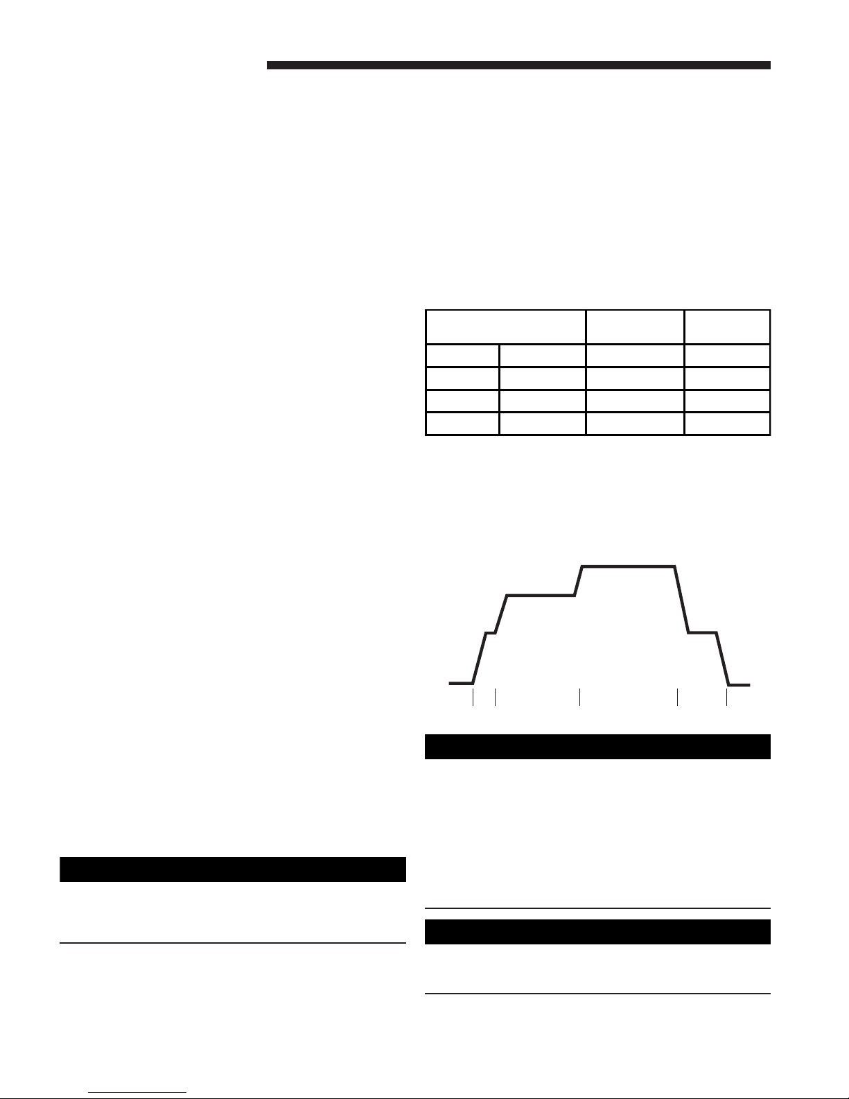
Cooling: The fan delay-off period is set by dip switches on
the Integrated Furnace Control. The options for cooling
delay off is field selectable by dip switches #5 and #6.
The following table and graph explain the delay-off settings:
COOLING OFF - DELAY OPTIONS
SWITCH SETTINGS SELECTION
5 - OFF 6 - OFF NONE SAME
5 - ON 6 - OFF 1.5 MINUTES 100% *
5 - OFF 6 - ON 3 MINUTES 50%
5 - ON 6 - ON ** 50 - 100%
* - This setting is equivalent to BAY24X045 relay benefit
** - This selection provides ENHANCED MODE, which is a
ramping up and ramping down of the blower speed to provide
improved comfort, quietness, and potential energy savings.
See Wiring Diagram notes on the unit or in the Service Facts
for complete wiring setup for ENHANCED MODE. The graph
which follows, shows the ramping process.
100% if necessary
80%
Dehumidify
50%
Fast Coil Cooling
OFF
1
minute
BODILY INJURY CAN RESULT FROM HIGH VOLTAGE
ELECTRICAL COMPONENTS, FAST MOVING FANS, AND
COMBUSTIBLE GAS. FOR PROTECTION FROM THESE
INHERENT HAZARDS DURING INSTALLATION AND
SERVICING, THE ELECTRICAL SUPPLY MUST BE
DISCONNECTED AND THE MAIN GAS VALVE MUST BE
TURNED OFF. IF OPERATING CHECKS MUST BE PERFORMED WITH THE UNIT OPERATING, IT IS THE
TECHNICIAN’S RESPONSIBILITY TO RECOGNIZE THESE
HAZARDS AND PROCEED SAFELY.
The integrated furnace control is polarity sensitive. The hot
leg of the 115 VAC power must be connected to the BLACK
field lead.
7.5
minutes
!
▲
▲
WARNING
!
CAUTION
NOMINAL
AIRFLOW
50%
Efficiency
OFF
3
minutes
4 Page B-651-438
PERIODIC SERVICING REQUIREMENTS
Service Facts
!
WARNING
▲
Disconnect power to the unit before removing the blower
door. Allow a minimum of 10 seconds for IFC power supply
to drain to 0 volts. Failure to follow this warning could
result in property damage, personal injury or death.
!
WARNING
▲
CARBON MONOXIDE POISONING HAZARD
Failure to follow the service and/or periodic maintenance
instructions for the furnace and venting system, could
result in carbon monoxide poisoning or death.
1. GENERAL INSPECTION – Examine the furnace
installation annually for the following items:
a. All flue product carrying areas external to the furnace
(i.e. chimney, vent connector) are clear and free of
obstruction. A vent screen in the end of the vent (flue)
pipe must be inspected for blockage annually.
b. The vent connector is in place, slopes upward and is
physically sound without holes or excessive corrosion.
c. The return air duct connection(s) is physically sound,
is sealed to the furnace and terminates outside the
space containing the furnace.
d. The physical support of the furnace should be sound
without sagging, cracks, gaps, etc., around the base so
as to provide a seal between the support and the base.
e. There are no obvious signs of deterioration of the furnace.
2. FILTERS – Filters should be cleaned or replaced (with
high velocity filters only), monthly and more frequently
during high use times of the year such as midsummer
or midwinter.
3. BLOWERS – The blower size and speed determine the
air volume delivered by the furnace. The blower motor
bearings are factory lubricated and under normal
operating conditions do not require servicing. If motor
lubrication is required it should only be done by a
qualified servicer. Annual cleaning of the blower wheel
and housing is recommended for maximum air output,
and this must be performed only by a qualified servicer
or service agency.
4. IGNITER – This unit has a special hot surface direct
ignition device that automatically lights the burners.
Please note that it is very fragile and should be handled
with care.
!
CAUTION
▲
Do not touch igniter. It is extremely hot.
5. BURNER – Gas burners do not normally require
scheduled servicing, however, accumulation of foreign
material may cause a yellowing flame or delayed
ignition. Either condition indicates that a service call is
required. For best operation, burners must be cleaned
annually using brushes and vacuum cleaner.
Turn off gas and electric power supply. To clean burners,
remove burner box cover (6 to 8 screws) and top burner
bracket. Lift burners from orifices.
NOTE:
Be careful not to break igniter when removing burners.
Clean burners with brush and/or vacuum cleaner. Reassemble parts by reversal of the above procedure. The
burner box must be resealed when replacing box cover.
NOTE:
On LP (propane) units, some light yellow tipping of the
outer mantle is normal. Inner mantle should be bright blue.
Natural gas units should not have any yellow tipped flames.
This condition indicates that a service call is required. For
best operation, burners must be cleaned annually using
brushes and vacuum cleaner.
NOTE:
On LP (propane) units, due to variations in BTU content and
altitude, servicing may be required at shorter intervals.
!
WARNING
▲
CARBON MONOXIDE POISONING HAZARD
Failure to follow the service and/or periodic maintenance
instructions for the furnace and venting system, could
result in carbon monoxide poisoning or death.
6. HEAT EXCHANGER/FLUE PIPE – These items must be
inspected for signs of corrosion, and/or deterioration at the
beginning of each heating season by a qualified service
technician and cleaned annually for best operation. To
clean flue gas passages, follow recommendations below:
a. Turn off gas and electric power supply.
b. Inspect flue pipe exterior for cracks, leaks, holes or
leaky joints. Some discoloration of PVC pipe is normal.
c. Remove burner compartment door from furnace.
d. Inspect around insulation covering flue collector box.
Inspect induced draft blower connections from
recuperative cell and to the flue pipe connection.
e. Remove burners. (See 4.)
f. Use a mirror and flashlight to inspect interior of heat
exchanger, be careful not to damage the igniter, flame
sensor or other components.
g. If any corrosion is present, contact a service agency.
Heat exchanger should be cleaned by a qualified
service technician.
h. After inspection is complete replace burner box cover,
burners, and furnace door.
i. Restore gas supply. Check for leaks using a soap
solution. Restore electrical supply. Check unit for
normal operation.
7. COOLING COIL CONDENSATE DRAIN - If a cooling
coil is installed with the furnace, condensate drains
should be checked and cleaned periodically to assure
that condensate can drain freely from coil to drain. If
condensate cannot drain freely water damage could
occur. (See Condensate Drain in Installer’s Guide.)
!
CAUTION
▲
Label all wires prior to disconnection when servicing
controls. Wiring errors can cause improper and
dangerous operation.
Verify proper operation after servicing.
!
WARNING
▲
NEVER USE AN OPEN FLAME TO TEST FOR GAS LEAKS:
AN EXPLOSION COULD OCCUR, CAUSING INJURY OR
DEA TH.
Page B-651-438 5
Service Facts
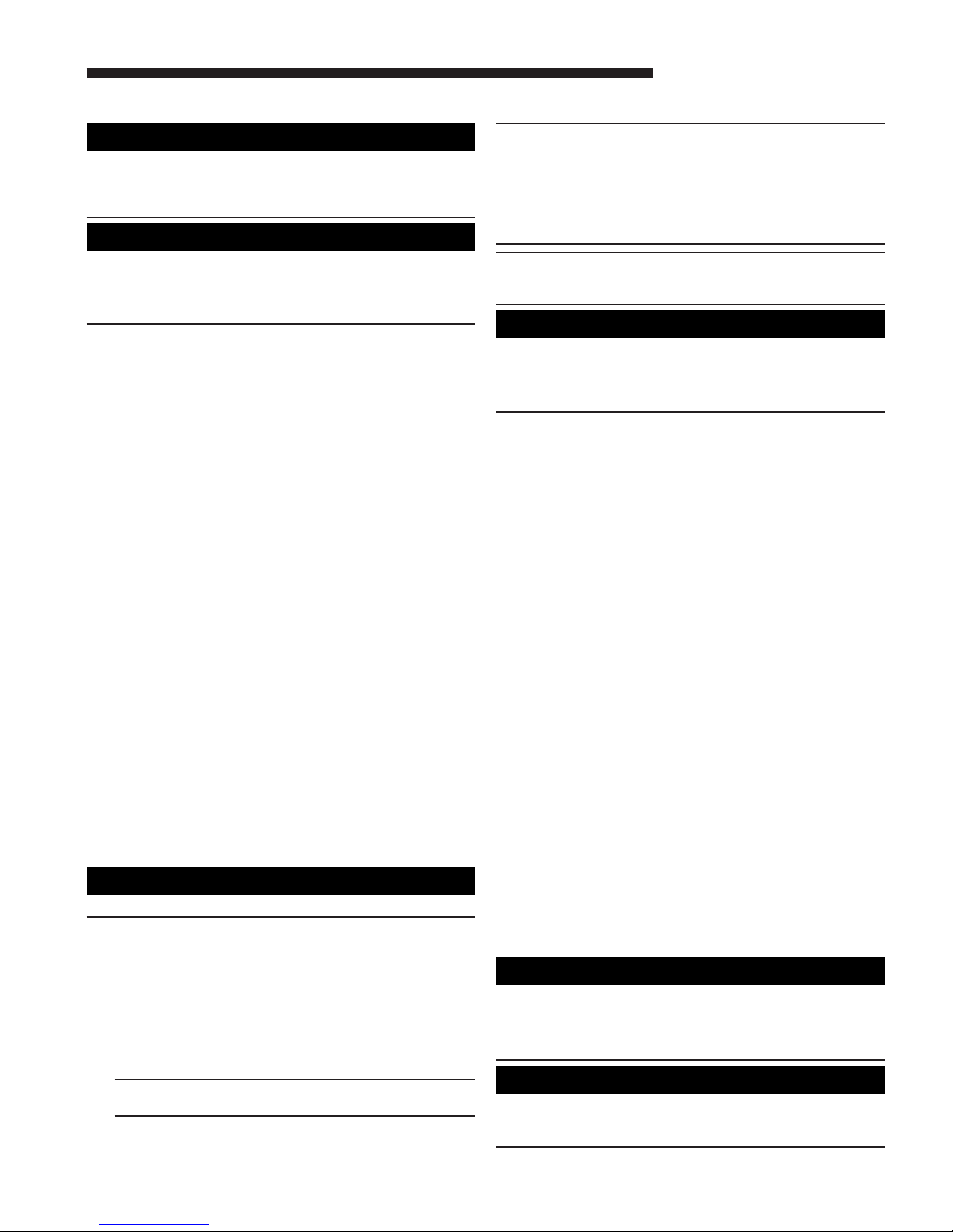
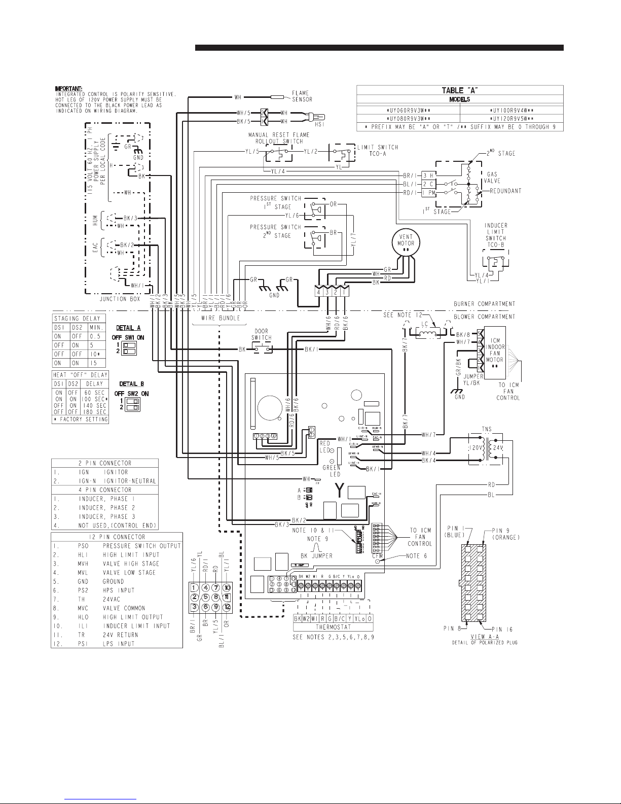
*UY WIRING DIAGRAM
6 Page B-651-438
 Loading...