

Page 1
Installation Instructions
Instrucciones de Instalacion
Instructions d'installation
COLONY SOFT DECK MOUNT TRIM KIT
JUEGO DECORATIVO PARA CUBIERTA COLONY
TROUSSE DE GARNITURE POUR MONTAGE SUR
PLAGE D’ÉVIER COLONY
Thank you for selecting American-Standard...the benchmark of fine
quality for over 100 years. To ensure that your installation proceeds smoothly-please read these instructions carefully before you begin.
Gracias por preferir American Standard…. El punto de referencia de la más fina calidad por más de
100 años. Para asegurar que su instalación se efectue de la mejor forma favor de leer estas
instrucciones cuidadosamente antes de empezar.
Nous vous remercions d'avoir choisi American Standard... synonyme de qualité
supérieure depuis plus de 100 ans. Pour s'assurer d'une installation sans
inconvénients, veuillez lire attentivement ces instructions avant de commencer.
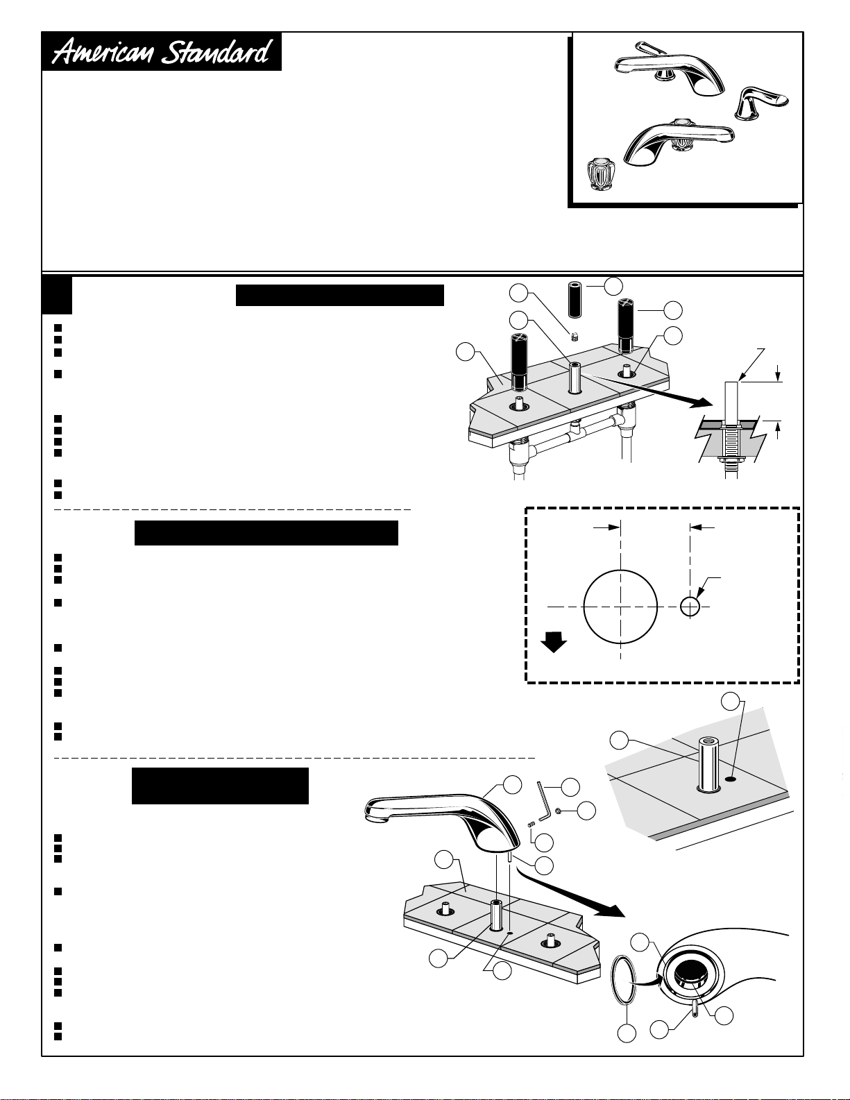
SPOUT INSTALLATION
1
Complete FINISHED DECK (A) before trim installation.
Turn off the water supplies.
Remove the GUARDS (1) from the VALVE BODIES (2). Remove the
SPOUT GUARD (3) and 1/4" PLUG (4) from the SPOUT SHANK (5).
The SPOUT SHANK (6) height should be 1" to 2" above the FINISHED
DECK (A). Cut the SPOUT SHANK (5) if necessary. Remove all burrs
and bevel the end of the shank. Failure to do so may damage
the SPOUT O-ring during installation and cause water leakage.
Drill a 3/16" HOLE (C) in the finished deck. See TEMPLATE for location.
Lubricate the SPOUT O-RING (6).
Remove the PLUG BUTTON (7) from the SPOUT (8).
Position the RUBBER RING (9) in the GROOVE (B) in the base of the SPOUT (8).
Push the SPOUT (8) down onto the SPOUT SHANK (5) and align the SPOUT PIN (12)
with the 3/16" DRILLED HOLE (C) in the FINISHED DECK (A).
Tighten the SET SCREW (10) securely with the 5mm HEX KEY (11).
Insert the PLUG BUTTON (7) into the SPOUT (8).
CAUTION
Turn off hot and cold water
supplies before beginning.
T975.400/400BP
T975.500/500BP
4
5
A
H
Certified to comply with ANSI A112.18.1
U.S. Patent No. D403,750
3
1
2
C
M968757D
REMOVE ALL
BURRS AND
BEVEL
1"- 2"
ARMADO
DE LA LLAVE
Complete la CUBIERTA TERMINADA (A) antes de instalar el juego decorativo.
Cierre el suministro de agua.
Quite los PROTECTORES (1) del CUERPO DE LAS VÁLVULAS (2). Quite el PROTECTOR
DEL GRIFO (3) y el TAPÓN (4) de 1/4 de pulgada (6,4 mm) del POSTE DEL GRIFO (5).
La altura del POSTE DEL GRIFO (5) debe ser de 1 a 2 pulgadas (25 a 51 mm) sobre
la CUBIERTA TERMINADA (A). Corte el POSTE DEL GRIFO (5) si es necesario. Quite todas
las rebabas y bisele el extremo del poste. Si no lo hace, puede dañar la junta tórica
del GRIFO durante la instalación y ocasionar fugas.
Taladre un AGUJERO (C) de 3/16 de pulgada (4,8 mm) en la cubierta terminada.
Consulte la PLANTILLA para conocer la ubicación.
Lubrique las JUNTAS TÓRICAS DEL GRIFO (6).
Quite el BOTÓN OBTURADOR (7) del GRIFO (8).
Coloque el ANILLO DE CAUCHO (9) en la RANURA (B) de la base del GRIFO (8).
Empuje el GRIFO (8) hacia abajo sobre el POSTE DEL GRIFO (5) y alinee el PASADOR DEL
GRIFO (12) con el AGUJERO PERFORADO (C) de 3/16 de pulgada (4,8 mm) en la CUBIERTA TERMINADA (A).
Apriete firmemente el TORNILLO DE SUJECIÓN (10) utilizando la LLAVE HEXAGONAL (11) de 5 mm.
Inserte el BOTÓN OBTURADOR (7) en el GRIFO (8).
INSTALLER
LE ROBINET
Terminer la PLAGE DE L’ÉVIER FINIE (A) avant d’installer les garnitures.
Couper l’alimentation d’eau.
Retirer les PROTECTEURS (1) des CORPS DE VANNE (2). Retirer
le PROTECTEUR DU BEC (3) et le TAMPON (4) de 6 mm de la TIGE
DU BEC (5).
La TIGE DU BEC (6) devrait dépasser la PLAGE DE L’ÉVIER
FINIE (A) d’une hauteur de 2,5 à 5,0 cm. Couper la TIGE DU
BEC (5) si nécessaire. Retirer toutes les barbures et niveler
l’extrémité de la tige. Sinon, le joint torique du BEC risque
d’être endommagé durant l’installation et causer des fuites d’eau.
Percer un TROU (C) de 5 mm dans la plage de l’évier finie. Se
reporter au GUIDE pour connaître l’emplacement.
Lubrifier le JOINT TORIQUE DU BEC (6) et
Retirer la CAPSULE DU TAMPON (7) du BEC (8).
Placer la BAGUE DE CAOUTCHOUC (9) dans la RAINURE (8) située dans la base du BEC (8).
Pousser le BEC (8) vers le bas dans la TIGE DU BEC (5) et aligner la GOUPILLE DU BEC (12) avec le
TROU PERCÉ (C) de 5 mm situé dans la PLAGE DE L’ÉVIER FINIE (A).
Serrer la VIS DE RÉGLAGE (10) fermement au moyen d’une CLÉ HEXAGONALE (11) de 5 mm.
Insérer la CAPSULE DU TAMPON (7) dans le BEC (8).
ADVERTENCIA: Cierre la tuberia de la ali mentación
del agua caliente y fría antes de comenzar lainstalación
ATTENTION
Fermer l'alimentation
d'eau chaude et froideavant de
commencer.
FRONT
8
A
5
C
11
10
12
20.5mm
(13/16")
3/16" DIA.
HOLE
TEMPLATE FOR
SPOUT ROLL
PIN LOCATION
PLANTILLA DE UBICACIÓN DEL
PASADOR DE GIRO DEL GRIFO
GUIDE POUR L’EMPLACEMENT DE LA
GOUPILLE CYLINDRIQUE DU BEC.
C
5
7
B
12
9
6
Page 2
2
VALVE TRIM
4
2
Fit ESCUTCHEON SEALS (1) into underside of VALVE ESCUTCHEONS (2).
Thread the VALVE ESCUTCHEONS (2) into the VALVE BODIES (3). Align the HANDLE
STEM (4) with the SLEEVE (5) as necessary. Thread the VALVE ESCUTCHEON (2) into
the BODIES (3) until the ESCUTCHEON (2) contacts the finished deck.
1
3
JUEGO DE ESCUDETE
Coloque los SELLOS DE LOS CHAPETONES (1) en la parte inferior de los CHAPETONES
DE LAS VÁLVULAS (2).
Enrosque los CHAPETONES DE LAS VÁLVULAS (2) en los CUERPOS DE LAS VÁLVULAS (3).
Alinee el TALLO DE LA LLAVE (4) con el MANGUITO (5) si es necesario. Enrosque el
CHAPETÓN DE LA VÁLVULA (2) en el CUERPO (3) hasta que el CHAPETÓN (2) haga contacto con la cubierta terminada.
5
KIT D'ÉCUSSON
Insérer les JOINTS DE ROSACE (1) dans la face inférieure des JOINTS DE VANNE (2).
Enfiler les JOINTS DE VANNE (2) dans les CORPS DE VANNE (3). Aligner la TIGE DE LA POIGNÉE (4) avec le MANCHON (5),
au besoin. Enfiler le JOINT DE VANNE (2) dans les CORPS (3) jusqu’à ce que le JOINT (2) entre en contact avec la plage de l’évier finie.
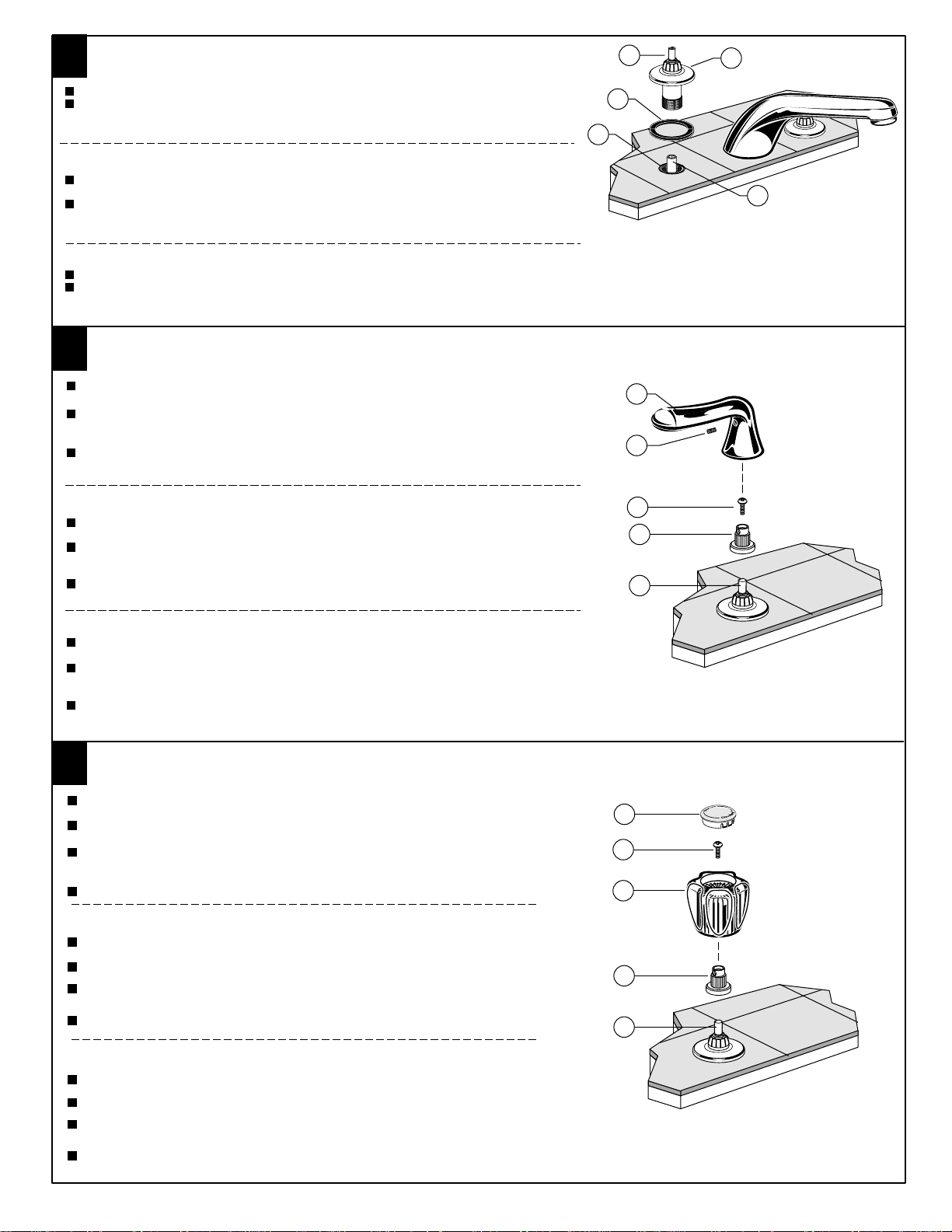
INSTALL LEVER HANDLE TRIM
3
Turn HANDLE STEM (1) to "OFF" position.
Place the HANDLE ADAPTER (2) on the HANDLE STEM (1).
Install the ADAPTER SCREW (3) and tighten securely.
Position LEVER HANDLE (4) and place on ADAPTER (2). Install the
HANDLE SCREW (5) and tighten securely.
INSTALACIÓN DE LA MANIJA
Gire el TALLO DE LA LLAVE (1) a la posición de cierre.
Coloque el ADAPTADOR DE LA LLAVE (2) en el TALLO DE LA LLAVE (1). Instale el TORNILLO
DEL ADAPTADOR (3) y apriételo firmemente.
Ajuste la posición de la LLAVE DE PALANCA (4) y colóquela sobre el ADAPTADOR (2).
Coloque el TORNILLO DE LA LLAVE (5) y apriételo firmemente.
4
5
3
2
1
INSTALLATION DE LA POIGNÉE
Placer la TIGE DE LA POIGNÉE (1) en position « FERMÉE ».
Placer l’ADAPTATEUR DE POIGNÉE (2) sur la TIGE DE LA POIGNÉE (1). Installer la VIS
D’ADAPTATION (3) et serrer fermement.
Mettre la MANETTE À VOLANT (4) en position et la placer sur l’ADAPTATEUR (2).
Installer la VIS POUR MANETTE (5) et serrer fermement.
INSTALL ACRYLIC HANDLE TRIM
4
Turn HANDLE STEM (1) to "OFF" position.
Place the HANDLE ADAPTER (2) on the HANDLE STEM (1).
Position ACRYLIC HANDLE (3) and install on ADAPTER (2).
Install the HANDLE SCREW (4) and tighten securely.
Push in INDEX BUTTON (5). (Hot-left side , Cold-Right side)
INSTALE LAS MANIJAS ACRÍLICAS
Gire el TALLO DE LA LLAVE (1) a la posición de cierre
Coloque el ADAPTADOR DE PIE DE LA MANIJA (2) en el PIE DE LA MANIJA (1).
Ubique la MANIJA ACRÍLICA (3) en el ADAPTADOR DE PIE DE LA MANIJA (2).
Instale el TORNILLO DE MANIJA (4) y ajuste bien.
Presione sobre BOTÓN ÍNDICE (5).
INSTALLER LES POIGNÉES EN ACRYLIQUE
Placer la TIGE DE LA POIGNÉE (1) en position « FERMÉE ».
Placer l’ADAPTATEUR DE POIGNÉE (2) sur la TIGE DE LA POIGNÉE (1).
Placer la POIGNÉE EN ACRYLIQUE (3) sur la l’ADAPTATEUR DE POIGNÉE (2).
Installer les VIS POUR LES POIGNÉES (4) et bien serrer.
Insérer le BOUTON INDICATEUR (5).
5
4
3
2
1
H
M968757D
Page 3
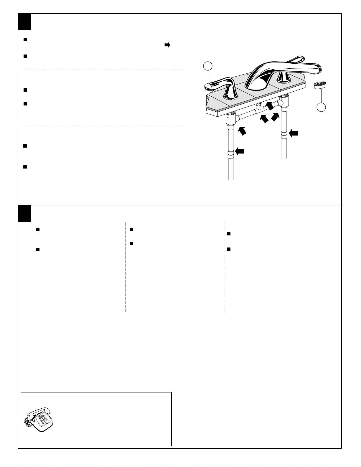
TEST INSTALLED FAUCET
5
Remove STREAM STRAIGHTENER (1). With handles in OFF position,
turn on water supplies and check all connections for leaks.
Operate both handles to flush water lines thoroughly.
Replace STREAM STRAIGHTENER (1).
PRUEBA DE LA LLAVE INSTALADA
Quite el REGULADOR DEL CHORRO DE AGUA (1). Cierre las llaves, abra el
suministro de agua y revise las conexiones para asegurar que no tengan fugas.
Girar ambos manerales para dejar fluir el agua de las tuberias.
Accionar la varilla del drenaje y cheque contra fugas. Reinstalar el
REGULADOR DEL CHORRO DE AGUA (1).
TESTER L'INSTALLATION DU ROBINET
Retirer le DISPOSITIF DE REDRESSEMENT DU JET (1). Tout en gardant les
poignées en position FERMÉE, mettre l’alimentation d’eau en marche
et vérifier tous les raccords pour s’assurer qu’il n’y ait pas de fuites.
Ouvrir les deux POIGNÉES, rincer les conduits d'eau abondamment.
Opérer la TIGE DE LEVAGE et vérifier si le VIDAGE fuit. Replacer
DE REDRESSEMENT DU JET (1).
2
1
le DISPOSITIF
If faucet drips proceed as
6
follows:
Stream straightener may accumulate
dirt causing distorted and reduced
water flow. Remove aerator and rinse
clean.
If spout drips, operate handles
several times from OFF to ON position.
Do not force-handles turn only 90˚.
CARE INSTRUCTIONS:
DO: SIMPLY RINSE THE PRODUCT CLEAN WITH
CLEAR WATER. DRY WITH A SOFT COTTON
FLANNEL CLOTH.
DO NOT: DO NOT CLEAN THE PRODUCT WITH
SOAPS, ACID, POLISH, ABRASIVES, HARSH
CLEANERS, OR A CLOTH WITH A COARSE
SURFACE.
Si la llave gotea proceda como
sigue:
El aireador tal vez acumule suciedad,
causando un flujo no uniforme del agua
Remover el aireador, enjuagar y limpiar.
Si la salida gotea gire los manerales
varias veces desde la posición de cerrado a la posición de abierto. No force
los manerales, solamente girelos a 90
grados.
INSTRUCCIONES DE CUIDADO
DEL PRODUCTO:
LIMPIE EL PRODUCTO CON AGUA LIMPIA
Y SÉQUELO CON UNA TELA SUAVE DE
FRANELA DE ALGODÓN.
NO LIMPIE EL PRODUCTO CON JABÓN,
ÁCIDOS, PULIDORES, ABRASIVOS,
LIMPIADORES FUERTES O TELAS ÁSPERAS.
Si le robinet coule, suivre les instructions
suivantes:
La saleté peut s'accumuler dans l'aérateur et
causer un débit d'eau plus faible ou inégal.
Enlever l'aérateur et rincer.
Si le bec coule, ouvrir et fermer les poignées
plusieurs fois de suite. Ne pas forcer. Tourner
seulement à 90˚.
INSTRUCTIONS POUR L'ENTRETIEN
FAIRE : SIMPLEMENT RINCER LE PRODUIT AVEC DE
L'EAU CLAIRE JUSQU'À CE QU'IL SOIT PROPRE SÉCHER
AVEC UN LINGE DE FLANELLE DE COTON DOUX.
NE PAS FAIRE : NE PAS NETTOYER LE PRODUIT AVEC
DES SAVONS, DE L'ACIDE, DU POLISH, DES ABRASIFS,
DES NETTOYANTS AGRESSIFS OU UN LINGE À TEXTURE
RUGUEUSE.
For toll-free information and answers to your questions, call:
Para información y respuestas a sus preguntas, llame sin costo al:
Pour information et réponses à vos questions, composer sans frais:
Weekdays Días laborales de las Sur semaine:
CANADA 1-800-387-0369 (TORONTO 1-905-306-1093)
Weekdays Días laborales de las Sur semaine:
Product names listed herein are trademarks of American Standard Inc.
©American Standard Inc. 2001
1 800 442-1902
8:00 to 8:00 p.m. EST
8:00 to 7:00 p.m. EST
ASSISTANCE TÉLÉPHONIQUENUMBERO DE EMERGENCIAHOTLINE FOR HELP
M968757D
Page 4
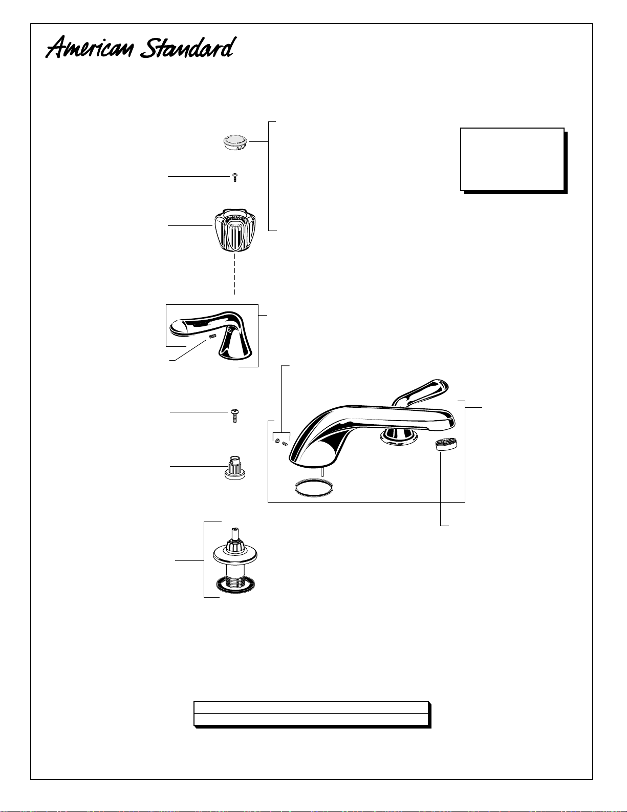
M918504-0070A
SCREW
Tornillo
VIS
M908423-0070A
ACRYLIC HANDLE
Maneral Acrilico
POIGNÉE ACRYLIQUE
M918075-0070A
HANDLE SCREW
TORNILLO DE LA MANIJA
VIS DE LA POIGNÉE
M918504-0070A
SCREW
TORNILLO
VIS
COLONY SOFT DECK MOUNT TRIM KIT
JUEGO DECORATIVO PARA CUBIERTA COLONY
TROUSSE DE GARNITURE POUR MONTAGE SUR
PLAGE D’ÉVIER COLONY
MODEL NUMBER
NÚMERO DE MODELO
H
M950144-0070A
INDEX, BUTTON, HOT
Boton Indicador de
Agua Caliente
BOUTON INDEX, CHAUD
M950143-0070A
INDEX, BUTTON, COLD
Boton Indicador de
Agua Fria
BOUTON INDEX, FROID
M916803-YYY0A
METAL LEVER HANDLE
MANIJA METÁLICA
POIGNÉE MÉTALLIQUE PLEINE
M961461-YYY0A
BUTTON AND SCREW
BOTON Y TORNILLO
BOUTON ET VIS
NUMÉRO DE MODÈLE
T975.400BP
T975.400
T975.500BP
T975.500
M961640-YYY0A
SPOUT
BOQUILLA
BEC
M918021-0070A
ADAPTER
ADAPTAR
APPROPRIER
M961460-0020A
VALVE ESCUTCHEON KIT
JUEGO DE ESCUDETE
KIT D'ÉCUSSON
Replace the "YYY" with appropriate finish code
Reemplace las letras "YYY" por el código de acabado
Remplacer le "YYY" par le code de finition approprié
CHROME, CROMO, CHROME
POLISHED BRASS, BRONCE PULIDO, LAITON POLI
002
099
028678-0070A
STREAM STRAIGHTENER
REGULADOR DE CHORRO DE AGUA
REDRESSEUR DE JET
M968757D
Page 5

Installation
Instructions
DECK MOUNT
TUB FILLERS
COLONY DIVERTER & PERSONAL
SHOWER TRIM KIT
Thank you for selecting American-Standard...the benchmark
of fine quality for over 100 years.
T990 SERIES
To ensure that your installation proceeds smoothly--please
read these instructions carefully before you begin.
INDEX
BUTTON
HANDLE
SCREW
HANDLE
SHOWER
ESCUTCHEON
VALVE
ESCUTCHEON
RUBBER RING
SHOWER
HOSE
Certified to comply with ANSI A112.18.1
U.S. Patent No. D403,750
HAND SHOWER
SEAL WASHER
M968356
HOLDER
INSTALL DIVERTER VALVE TRIM
1
REMOVE THE DIVERTER GUARD.
Place the ESCUTCHEON SEAL over the DIVERTER BODY.
Thread the VALVE ESCUTCHEON into the DIVERTER BODY.
Align the HANDLE STEM with the SLEEVE as necessary.
Thread the VALVE ESCUTCHEON into the BODY until the
ESCUTCHEON contacts the finished deck.
SEAL
WASHER
DIVERTER
GUARD
HANDLE
STEM
ESCUTCHEON
SEAL
SLEEVE
VALVE
ESCUTCHEON
FINISHED
DECK
Page 6

S
R
INSTALL HANDLE TRIM
2
Turn HANDLE STEM fully clockwise (Tub Filler position).
INDEX
BUTTON
HANDLE
SCREW
Place the HANDLE on the HANDLE STEM. Install the
HANDLE SCREW and tighten securely.
Push the INDEX BUTTON into the top of HANDLE.
INSTALL HAND SHOWER
3
HANDLE
HANDLE
STEM
Unscrew the HOLDER from the SHOWER ESCUTCHEON. Slip the
SHOWER HOSE through the HOLDER and the SHOWER ESCUTCHEON.
Insert a SEAL WASHER into the SHOWER HOSE CONNECTOR.
Pull out the SLEEVE GUARD and HOSE. Unthread the SLEEVE GUARD
from the HOSE END connection. Be careful not to allow the HOSE to
fall back through the SLEEVE.
Thread the SHOWER HOSE onto the HOSE END connection and tighten
securely.
SLEEVE
GUARD
SHOWER HOSE
EAL WASHE
HAND SHOWER
SEAL WASHER
SHOWER HOSE
HOLDER
SHOWER ESCUTCHEON
RUBBER RING
HOSE END
HOSE
SLEEVE
Apply a sealant around the HOSE HOLE.
Thread the SHOWER ESCUTCHEON into the SLEEVE until the ESCUTCHEON
contacts the finished deck.
Loosen the SET SCREW in the SHOWER ESCUTCHEON and rotate the
ESCUTCHEON towards the center of the tub. Retighten the SET SCREW.
Thread the HOLDER into the SHOWER ESCUTCHEON.
Insert a SEAL WASHER into the SHOWER HOSE
connector and connect the HAND SHOWER.
Place the HAND SHOWER into the HOLDER.
HAND SHOWER
SEAL WASHER
HOLDER
SET SCREW
SHOWER
ESCUTCHEON
SLEEVE
SEALANT
HOTLINE FOR HELP
For toll-free information and answers to your questions, call:
1 (800) 442-1902
Weekdays 8:00 a.m. to 7:00 p.m. Eastern Time
IN CANADA 1-800-387-0369 (TORONTO 1-905-306-1093)
Product names listed herein are trademarks of American Standard Inc.
©American Standard Inc. 2000
M968356
Page 7

Installation
Instructions
DECK MOUNT
TUB SYSTEMS
R800 SERIES
R810 SERIES
ROUGH VALVE KIT
Thank you for selecting American-Standard...
the benchmark of fine quality for over 100 years.
To ensure that your installation proceeds smoothly--please
read these instructions carefully before you begin.
ROUGHING-IN
1
1. DECK THICKNESS
2. FINISHED DECK
3. FITTING MOUNTING SURFACE
4. ACRYLIC BATHS
1
(2) 1-3/8 D
HOLES
3
FITTING
MOUNTING
SURFACE
2
FINISHED
DECK
1-3/8 D
MAX.
1" D
1/2" COPPER
INLET SUPPLIES
8" to 12"
10" for R810
1 D MAX.
ACRYLIC
BATH
MOUNTING
4
7-1/8
R810 SERIES
R800 SERIES
Certified to comply with ANSI A112.18.1
U.S. Patent No. D403,750
TOTAL DECK THICKNESS UP TO 2-1/2"
FINISHED DECK VARIABILITY ACCOMMODATES
DECKING MATERIAL (TILE, MARBLE, CORIAN®...)
TO 1" THICK
ADJUSTABILITY, TO 1-1/2" THICK
ADJUSTABILITY, TO 1-1/2" THICK
1" D
8" to 12"
10" for R810
DECK MOUNTING HOLES
M968650C
(2) 1-3/8 D
HOLES
MOUNT SPOUT SHANK
2
Drill holes in mounting deck as shown. The maximum allowable deck thickness is 1-1/2".
Insert the SPOUT SHANK through the mounting deck from below. Assemble the SPOUT SHANK LOCK RING so it
is flush with the top of the threads on the SHANK.
SPOUT SHANK
LOCK RING
SPOUT SHANK LOCK RING FLUSH WITH
TOP OF THREADS ON SPOUT SHANK
FRICTION WASHER
MOUNTING NUT
SPOUT SHANK
1-1/2 MAX.
SPOUT SHANK
FITTING
MOUNTING
DECK
Page 8

MOUNT VALVE BODIES
3
Cut the copper outlet tubes of the VALVE BODIES as required.
(Not necessary for R810).
Insert the HOT and COLD VALVE BODIES into the TEE. (Not
necessary for R810). The HOT VALVE BODY is
marked with a red label.
Insert the VALVE BODIES and TEE through the mounting
deck from below. Assemble the VALVE LOCK RINGS so
they are flush with the top of the VALVE BODIES.
Insert the SPOUT SHANK into the TEE.
(Not necessary for R810).
Tighten the VALVE BODY and SHANK MOUNTING
NUTS securely.
FRICTION WASHER
Fasten the VALVE LOCK RING to the wooden mounting
surface with #8 screws (not provided).
SOLDER CONNECTIONS
4
Connect the water supply lines to the copper inlet tubes of the VALVE BODY.
VALVE
BODY
FITTING
MOUNTING
DECK
VALVE
LOCK RING
MOUNTING NUT
VALVE LOCK RING FLUSH WITH
TOP OF THREADS ON VALVE SHANK
VALVE
LOCK RING
# 8 SCREWS
SPOUT
SHANK
HOT
TEE
OUTLET TUBE
(CUT AS REQUIRED)
SPOUT GUARD
1/4" PLUG
COLD
Solder all TEE and WATER SUPPLY CONNECTIONS.
Remove the GUARD from the SPOUT SHANK. Assemble the 1/4" PLUG to
the SPOUT SHANK with a thread sealant.
Turn on the water supplies and check all connections for leakage.
Replace the GUARD on the SPOUT SHANK. Turn off the water supplies.
SERVICE
5
TO CHANGE THE DIRECTION OF HANDLE ROTATION
Turn off the water supplies.
Turn HANDLE to the off position.
Unscrew the VALVE LOCK NUT and remove.
A 17mm deep socket is required.
Remove the CARTRIDGE by pulling upon the SLEEVE.
Remove the SLEEVE from the CARTRIDGE.
Remove the SPRING CLIP.
Remove the STOP WASHER. Turn it 90˚ and replace.
Replace the SPRING CLIP.
Reverse the above steps to reassembly the components.
If the spout drips, operate the handles several times
from the off to the on position. Do not force - the handles only turn 90˚
STOP
WASHER
90
VALVE
CARTRIDGE
TEE
CONNECTIONS
WATER SUPPLY
CONNECTIONS
DEEP SOCKET
17mm (11/16")
VALVE
LOCK NUT
SCREW
SLEEVE
SPRING
CLIP
M968650C
Page 9

VALVE LOCK RING
M906671-0070A
VALVE LOCK NUT
A911546-0070A
DECK MOUNT TUB SYSTEMS
MODEL NUMBERS
R800
R810
SPINDLE
903898-0070A
VALVE CARTRIDGE
994053-0070A
VALVE MOUNTING KIT
M962278-0070A
SCREW
918319-0070A
SPOUT LOCK RING
A906110-0070A
SPOUT MOUNTING KIT
M962279-0070A
DEEP SOCKET
17mm (11/16")
M962273-0070A
SOCKET NOT INCLUDED
WITH FITTING
HOTLINE FOR HELP
For toll-free information and answers to your questions, call:
1 (800) 442-1902
Weekdays 8:00 a.m. to 7:00 p.m. Eastern Time
IN CANADA 1-800-387-0369 (TORONTO 1-905-306-1093)
Product names listed herein are trademarks of American Standard Inc.
C
American Standard Inc. 2003
R810 SERIES
*WITH BRAZED TEE
M968650C
Page 10

Installation
3/8 D
5-5/16
Instructions
DECK MOUNT
TUB FILLERS
DIVERTER & PERSONAL SHOWER
ROUGH VALVE KIT
Thank you for selecting American-Standard...the benchmark
of fine quality for over 100 years.
R890 SERIES
To ensure that your installation proceeds smoothly--please
read these instructions carefully before you begin.
ROUGHING-IN
1
1-3/8 D
HOLE
1
3
1/2" NPT
FITTING
MOUNTING
SURFACE
3-5/8
1-3/8 D
MAX.
TUB
SHW
6 to 18
FINISHED
DECK
4-5/16
2
1-3/8 D
MAX.
1/2" NPT INLET
ACRYLIC
BATH
MOUNTING
1-
4
1. DECK THICKNESS
2. FINISHED DECK
3. FITTING MOUNTING SURFACE
4. ACRYLIC BATHS
Certified to comply with ANSI A112.18.1
U.S. Patent No. D403,750
M968355D
TOTAL DECK THICKNESS UP TO 2-1/2"
FINISHED DECK VARIABILITY ACCOMMODATES
DECKING MATERIAL (TILE, MARBLE, CORIAN®...)
TO 1" THICK
ADJUSTABILITY, TO 1-1/2" THICK
ADJUSTABILITY, TO 1-1/2" THICK
1-3/8 D HOLE
FOR DIVERTER
6 to 18
1-3/8 D HOLE
FOR HAND
SHOWER
DECK MOUNTING HOLES
LOCATION OF R890 WHEN USED WITH R800
2
R800 ROUGH VALVE KIT
"A" DIMENSION CAN BE
FLEXIBLE TO
ACCOMMODATE
CUSTOMER'S
REQUIREMENTS
COLD
INLET
HOT
INLET
8" to 12"
HOT AND COLD
VALVE BODIES
R890 SERIES DIVERTER & PERSONAL
SHOWER ROUGH VALVE KIT
A A 6" to 18"
BATH SPOUT
CONNECTION
1/2" COPPER WATER
TUBE INLET (MIXED
SUPPLY FROM BATH
FITTING)
PLUMBER TO MAKE ALL PIPING CONNECTIONS
BETWEEN VALVE BODIES, SUPPLY TO TRANSFER
VALVE AND CONNECTION TO BATH SPOUT.
PIPING SHOWN SHADED IS NOT SUPPLIED
AND MUST BE FURNISHED BY INSTALLER.
SHW
DIVERTER
VALVE
TUB
HOSE OUTLET
(MIXED SUPPLY
TO HAND SHOWER)
1/2" COPPER WATER
TUBE (MIXED SUPPLY
TO TUB FILLER SPOUT)
HAND SHOWER
CONNECTION
Page 11

INSTALLATION
(
Y
S
E
GUARD
OSE
UB OU
T
OSE
5
3
NOTE: Use thread sealant on all threaded connections.
Drop the SLEEVE (1) into the hole in the mounting deck.
Assemble the WASHER (2) and LOCKNUT (3) to the SLEEVE (1) and
tighten securely.
For copper water tube installations, make two 4" long adapter nipples
( 1/2" Male NPT x 1/2" CWT ). Thread nipples into the inlet and tub
outlet of the DIVERTER BODY. Tighten connections securely. Do Not Solder
these Connections on the DIVERTER BODY. Damage may occur.
Thread HOSE (4) into the SHOWER CONNECTION (5) of the DIVERTER BODY (6)
and tighten securely. Check with local plumbing codes for backflow
prevention requirements. Install a backflow prevention device if required.
Assemble MOUNTING NUT (7) and WASHER (8) onto DIVERTER BODY (6).
Insert the DIVERTER BODY (6) through the mounting deck from below.
Assemble the VALVE LOCK RING (9) so it is flush with the top of
the DIVERTER BODY (6).
Position the DIVERTER BODY (6) as required and
VALVE LOCK
RING FLUSH WITH
TOP OF THREADS ON
VALVE SHANK
tighten the MOUNTING NUT (7) securely.
#8 SCREWS
FITTING
MOUNTING
SURFACE
1-3/8"
1
9
Dia. HOLE
FOR HAND
SHOWER
2
3
8
7
6
WATER INLET
4" LONG
ADAPTER
NIPPLES
Fasten the VALVE LOCK RING (9) to the wooden
mounting surface with #8 screws (not provided).
Connect the water inlet and tub outlet lines to
the DIVERTER BODY (6).
4
TEST
Note: Test Cap not provided.
Cap the HOSE OUTLET. Remove the DIVERTER GUARD.
Remove the SPOUT GUARD. Assemble the 1/4" PLUG to the SPOUT
SHANK with a thread sealant. See the R800 SERIES ROUGH VALVE KIT
instructions for details.
Turn on the water supplies.
Rotate the DIVERTER SLEEVE back and forth fully.
Check all connections for leakage.
Turn off the water supplies. Replace the DIVERTER
1/2" COPPER WATER
TUBE (MIXED SUPPLY
TO TUB FILLER SPOUT)
GUARD and the SPOUT GUARD. Remove the CAP
from the HOSE OUTLET.
HOSE
5
Insert the HOSE through the SLEEVE from below the mounting deck.
Thread the SLEEVE GUARD onto the HOSE END connection.
#8 SCREWS
T
VALVE
BODY
DIVERTER
GUARD
DIVERTER
SLEEVE
HOSE OUTLET
MIXED SUPPL
TLE
LEEV
SLEEVE
1/2" COPPER WATER
TUBE INLET (MIXED
SUPPLY FROM BATH
FITTING)
CAP
H
H
Insert the SLEEVE GUARD into the SLEEVE.
SERVICE
6
TO REMOVE DIVERTER
SCREW
Turn off the water supplies.
Turn HANDLE to the off position.
DIVERTER SLEEVE
Remove the SLEEVE from DIVERTER by losening screw.
Using 14mm (9/16") Deep Socket, remove diverter.
DIVERTER
DEEP SOCKET
14mm (9/16")
M968355D
Page 12

923016-0070
SCREW
918319-0070A
DIVERTER SLEEVE
903898-0070A
DIVERTER & PERSONAL SHOWER
ROUGH VALVE KIT
MODEL NUMBER
R890
VALVE LOCK RING
M906671-0070A
VALVE MOUNTING KIT
M962278-0070A
SLEEVE
922700-0070A
DIVERTER
954559-0070A
SLEEVE MOUNTING KIT
M962280-0070A
HOSE
M
For toll-free information and answers to your questions, call:
IN CANADA 1-800-387-0369 (TORONTO 1-905-306-1093)
Product names listed herein are trademarks of American Standard Inc.
© American Standard Inc. 2004
Weekdays 8:00 a.m. to 7:00 p.m. EST
HOT LINE FOR HELP
Weekdays 8:00 a.m. to 8:00 p.m. EST
1-800 442-1902
IN MEXICO 01-800-839-12-00
M968355D
 Loading...