

Page 1
INSTALLATION & USER'S MANUAL
Advanced Clean
SpaLet™
Side Panel
Remote Panel
Thank you for purchasing this product.
After reading this manual, please keep it in a place where you can refer to it easily.
BE SURE TO FOLLOW THE SAFETY PRECAUTIONS.
Failure to follow the safety precautions may result in serious accidents in some circumstances.
Each of these items are extremely important for safety, and should be strictly observed.
In the event that an accident occurs as a result of improper usage, American Standard
will assume no responsibility for damages.
©2017 AS America Inc.
SPALET is a trademark of AS America, Inc.
760230-110
Page 2

INSTALLATION
TABLE OF CONTENTS
1. Important Safeguards ........................................................... 3
2. Product Description ............................................................. 5
3. Installing This Product ......................................................... 6
Installation Requirements ....................................................................6
Contents .............................................................................................................. 6
Ground Fault Circuit Breaker .......................................................................... 7
Power Supply ..................................................................................................7
Grounding ....................................................................................................... 7
Installation Location ........................................................................................ 7
Water Supply .................................................................................................. 7
Checking the Bathroom .................................................................................. 7
Measure the size of the Toilet ......................................................................... 8
Conditions for using Water Supply Hose ........................................................ 8
Illustrated Parts Breakdown ................................................................ 9
Overview .........................................................................................................9
Strainer ........................................................................................................... 9
Operating Panel ............................................................................................ 10
Installation .......................................................................................... 11
Operational Check .............................................................................. 16
4. Operation Manual / Table of Contents ................................17
2
Page 3

1. IMPORTANT SAFEGUARDS
When using electrical products, especially when children are present, the basic safety precautions should
always be observed.
READ ALL THE INSTRUCTIONS BEFORE USING THIS PRODUCT
The following safety terms are used in this manual to warn against different
hazardous situations:
DANGER– To reduce the risk of electrocution:
1. Do not place or store product where it can fall or be pulled into a tub or sink.
2. Do not place in or drop into water or other liquid.
3. Do not reach for a product that has fallen into water. Unplug immediately.
WARNING
To reduce the risk of burns, electrocution,
fire or injury to persons:
1. When small children, elderly persons, persons with limited mobility or people with
illness are using this product, ensure that the proper operating procedures are
followed at all times to ensure the user's safety.
2.
When you are using this product for a long period of time, set the seat
temperature to "Off".
For the following persons, be sure to set the seat temperature to "Off" when they are
using this product.
(Children, elderly persons, persons with illness, persons with limited mobility, persons
with sensitive skin, persons who are taking medicines that cause drowsiness,
persons who are intoxicated, or persons who are extremely fatigued.)
* Using the toilet for a long period of time without setting the seat temperature to "Off"
may result in low temperature burns.
Low Temperature Burns
A low temperature burn may occur when the skin has been in contact for some time
with an object at relatively low temperature (about 104 °F [40 °C]). Susceptibility to
burns also depends on an individual's skin sensitivity and other factors.
3. This product should be used only as described in this manual. Do not use
attachments that are not recommended by the manufacturer.
4. Never operate this product if it has a damaged cord or plug, if the plug is loose in the
outlet, if it is not working properly, or if it has been dropped or damaged. If the plug
is inserted or disconnected by holding the cord, the plug or cord may be damaged
resulting in fire or electric shock.
5. Keep the cord away from heated surfaces.
contunued on page 4
3
Page 4

6. Never block the air openings of the product. If lint or hair, etc. is stuck in the air
openings, remove it immediately.
7. Never use while sleeping or feeling drowsy.
8. Never drop or insert any object into any opening or hose.
9. Connect this product to a properly grounded outlet only. See Grounding Instructions.
10. This product should only be connected to a potable water supply line. Failure to do so
will cause problems in the operation.
11. Do not pull out or insert the power plug with wet hands.
12. Disconnect the power plug periodically and clean it with a dry cloth.
Dust accumulated on the power plug may cause fire.
13. Do not use outdoors or operate where aerosol (spray) products are being used or
where oxygen is being administered.
To reduce the risk of minor injury or property damage:
1. This product should only be connected to a 120 V AC, 60 Hz GFCI-protected outlet.
2. For care of the plastic parts, our company recommends the use of a mild liquid or an
all-purpose cleaner. Avoid using abrasive products (such as powdered cleansers) and
chlorine-based products (such as bleach), as these products can damage the
anti-bacterial properties of the plastic components.
3. If the toilet seat or the body cover is damaged, pull the power plug out of the outlet.
4. Do not stand on the toilet seat lid, as it may break.
5. Do not lean back against the lid during use, as this may damage or break the lid.
6. Install this product according to this installation manual. Improper installation may
result in electrocution, fire, or a water leak.
7.
Do not forcefully pull on the bidet nozzle or turn it as this may cause it to fail.
8. Do not apply unnecessary force to the water supply hose as it could result in
damage and cause water to leak
9. To prevent the toilet seat and toilet seat lid from slamming down, a damping
mechanism is provided to lower them gradually. If the toilet seat or toilet seat lid is
closed abruptly or too forcefully, this product could be damaged or fail.
SAVE THESE INSTRUCTIONS
4
4
Page 5

2. Product Description
This product incorporates a set of features to improve personal toilet hygiene and comfort. These
features include rear cleansing, front cleansing and a seat heater as well as the required controls for
these features.
This product includes a seat unit (with heated toilet seat, toilet seat lid, warm water tank, and power
cord), hardware for installing the seat unit on a toilet and connecting it to the water supply and this
installation and user's manual.
This product incorporates the following features:
rear cleansing with water flow strength controls
•
front cleansing with water flow strength controls
•
seat heater with heat level control
•
rear and front cleansing water temperature control
•
seat and water temperature indicators
•
rear and front nozzle self-cleaning
•
stop button for rear cleansing, front cleansing
•
Note:
When transporting the product, take care not to inadvertently bump or drop it.
•
This product has been already inspected using tap water. A small amount of water
•
may be detected when installing the unit; this should not be a cause for concern.
5
Page 6
3. Installing This Product
Installation Requirements
Before installing this product, ensure that each of the following installation
requirements are met.
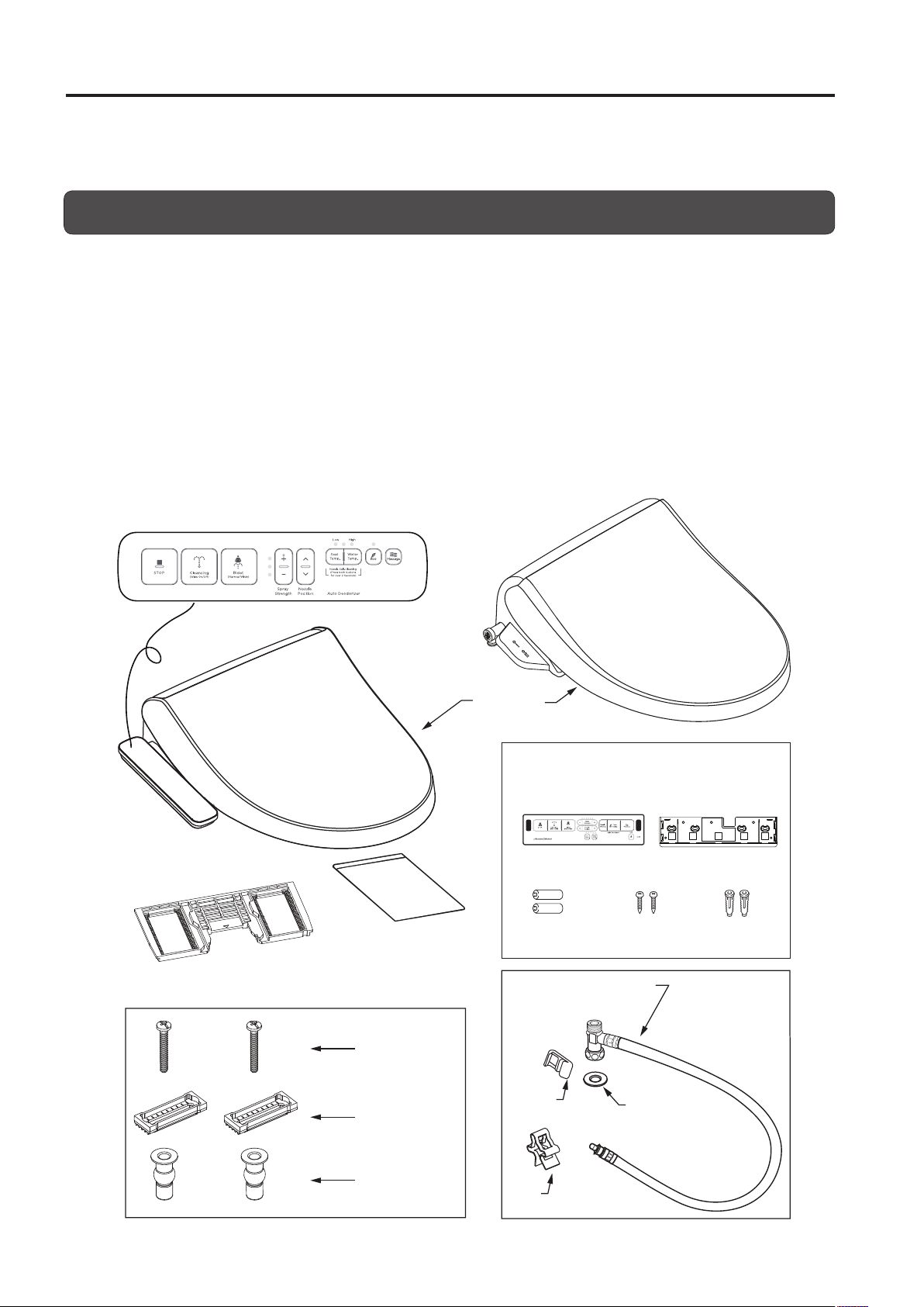
Contents
Remove the parts from the box and make sure all the parts in the parts list (below) are present. Inspect
the parts carefully to make sure they are in good condition.
If any part is damaged or missing, do not install this product. Contact a customer service representative
for the part(s) you need.
The following parts are included:
Seat unit (with heated toilet seat, toilet seat lid and power cord)
•
Mounting plate
•
Manual
•
Mounting bolts, brackets, and bushings (2 pieces each)
•
Seat unit water supply hose (with 1 clip and 1 washer)
•
Side Panel
Seat unit
FOR REMOTE VERSION ONLY:
Remote control
•
Bracket
•
Batteries
•
Wood screw
•
Plastic anchors
•
*Remote control unit and bracket are
packed in the box.
Mounting plate
(This plate attaches to the seat unit.)
Mounting bolt
Bracket
Bushing
Manual
Remote control unit
For remote control unit
Batteries (2)
Water supply hose
(w/ T-junction)
Plastic
Clip
Clip
Wood
screws
Washer
Bracket
Plastic
anchors
6
Page 7
GROUNDING INSTRUCTIONS
Remote receiver
11-1/4"
(286mm)
2-3/16"
(56mm)
11-1/4"
(286mm)
2-3/16"
(56mm)
7-11/16"
(195mm)
7-11/16"
(195mm)
9-1/2"
(241mm)
6"
(152mm)
7-15/16"
(202mm)
14-7/8"
(378mm)
Side Panel
7-15/16"
(202mm)
10-9/16"
(269mm)
10 - 9/16"
(269mm)
14-7/8"
(378mm)
15-3/8"
(391mm)
15-3/8"
(391mm)
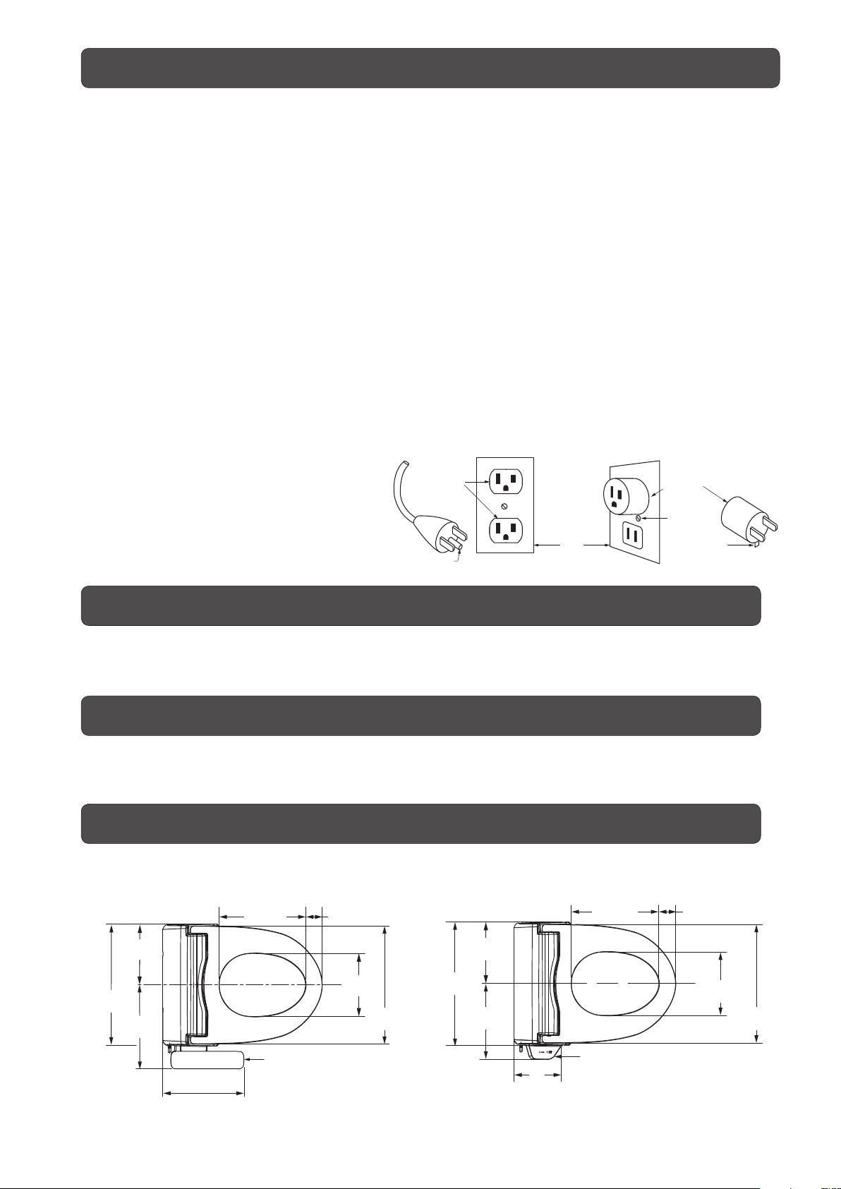
This product should be grounded. In the event of an electrical short circuit, grounding reduces the risk
of electric shock by providing an escape wire for the electric current. This product is equipped with a
cord having a grounding wire with a grounding plug. The plug must be plugged into an outlet that is
properly installed and grounded.
DANGER– Improper use of the grounding plug can result in a risk of electric shock.
If repair or replacement of the cord or plug is necessary, do not connect the grounding wire to either
at blade terminal. The wire with insulation having an outer surface that is green with or without yellow
stripes is the grounding wire.
Check with a qualified electrician or serviceman if the grounding instructions are not completely
understood, or if in doubt as to whether the product is properly grounded.
This product is for use on a nominal 120 V circuit, and has a grounding plug that looks like the plug
illustrated in sketch A. A temporary adapter, which looks like the adapter illustrated in sketches B and
C, may be used to connect this plug to a 2-pole receptacle as shown in sketch B if a properly grounded
outlet is not available. The temporary adapter should be used only until a properly grounded outlet
(sketch A) can be installed by a qualied electrician. The green colored rigid ear, lug, and the like
extending from the adapter must be connected to a permanent ground such as a properly grounded
outlet box cover. Whenever the adapter is used, it must be held in place by the screw.
If it is necessary to use an extension cord,
use only a three wire extension cord that
has a three-blade grounding plug, and
a three-slot receptacle that will accept
the plug on the product. Replace or
repair a damaged cord.
GROUNDED
OUTLET
GROUNDING PIN
A B C
GROUNDING
METHODS
GROUNDED
OUTLET
BOX
ADAPTER
METAL
SCREW
TAB FOR
METAL SCREW
Installation Location
In order to prevent damage to the electronic components, install this product at a location that
minimizes the possibility of it getting wet. In extremely humid conditions, provide adequate ventilation by
operating an exhaust fan or opening a window or door.
Water Supply
Use only the tap water line to supply water to this product. The use of any other type of water i.e. ground
water or well water may reduce functionality of product.
The tap water pressure must be 8.5 to 106.7 psi
(0.06 to 0.74 MPa, 0.6 to 7.5 kgf/cm2).
Checking the Bathroom
The dimensions required for mounting this product on a toilet are shown in the gure below. Check to
make sure there is sufficient space inside the bathroom and that there are no obstructions.
7
Page 8
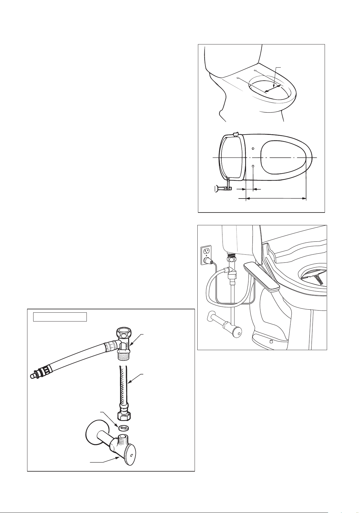
1. Measure the size of the toilet.
Depending on the size of the toilet, it may not be
possible to mount this product on it.
Make sure the toilet's dimensions are as shown in
the gure on the right.
2. Conditions for using water supply
hose (included)
17-5/16"-19-5/8"
(440-500 mm)
5-1/8" to 8-1/2"
(130 to 215 mm)
1-1/8" (30 mm)
or more
The length of the water supply hose included with this
product is 37-3/8" (950 mm), but a length of 31-1/2"
(800 mm) from the junction tting to the seat unit's
water supply socket is appropriate. (Refer to the gure
on the right)
Installation Figure
Water supply hose
(w/ T junction)
Toilet Water
supply hose
Seal washer
Water supply
valve
8
Page 9
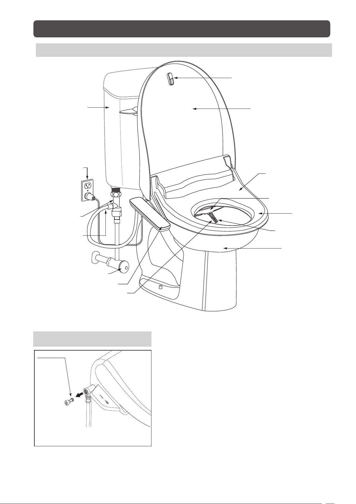
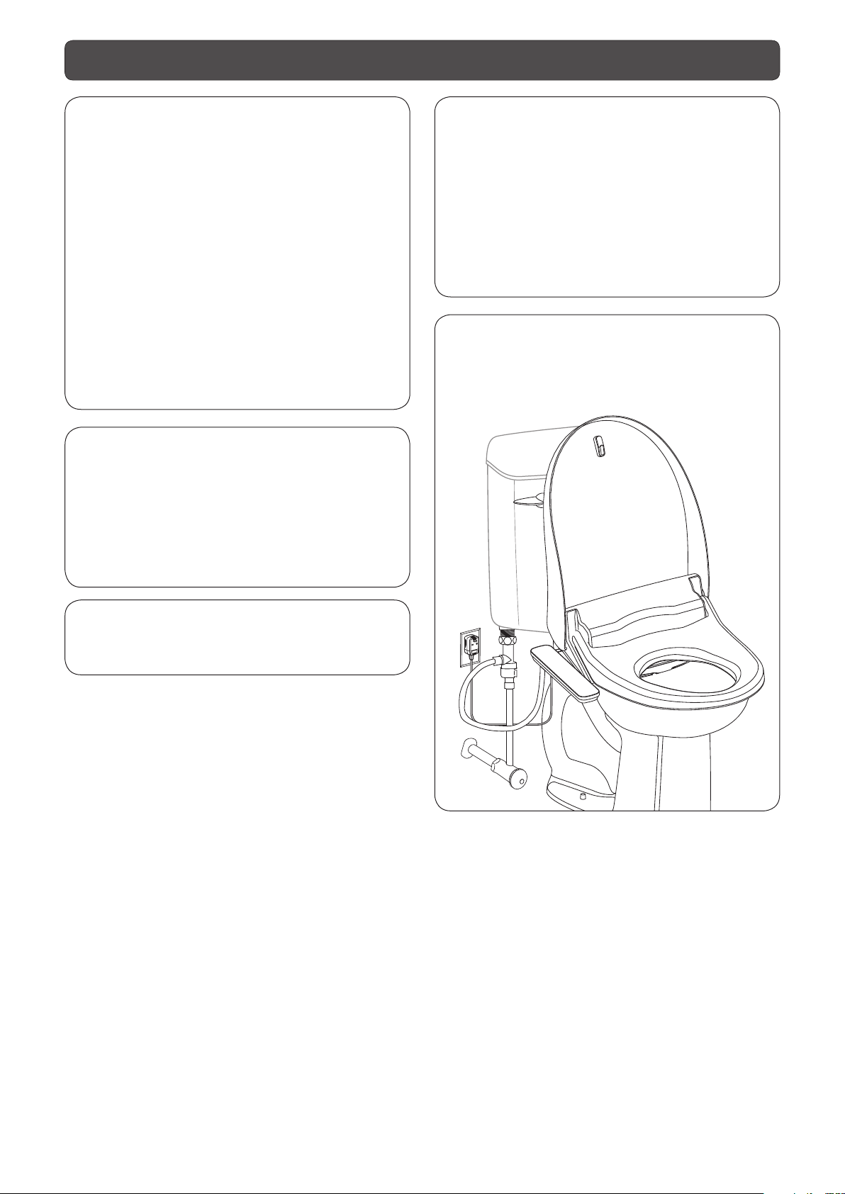
Illustrated Parts Breakdown
Overview
Lid Bumper
Toilet
Tank
Power Plug
T-Junction
Water Hose
(with T-Junction)
Water Valve
Lid
Seat Sensor
(built-in)
Nozzle Shutter
Seat
Nozzle
(posterior cleansing)
Bowl
Control Panel
Nozzle
(feminine cleansing)
Strainer
Strainer
* The strainer removes impurities
and debris from the tap water.
9
Page 10
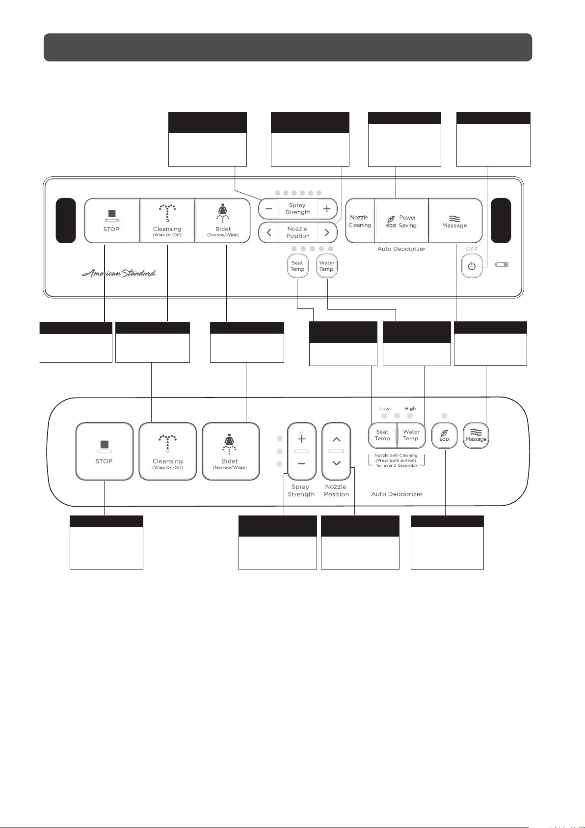
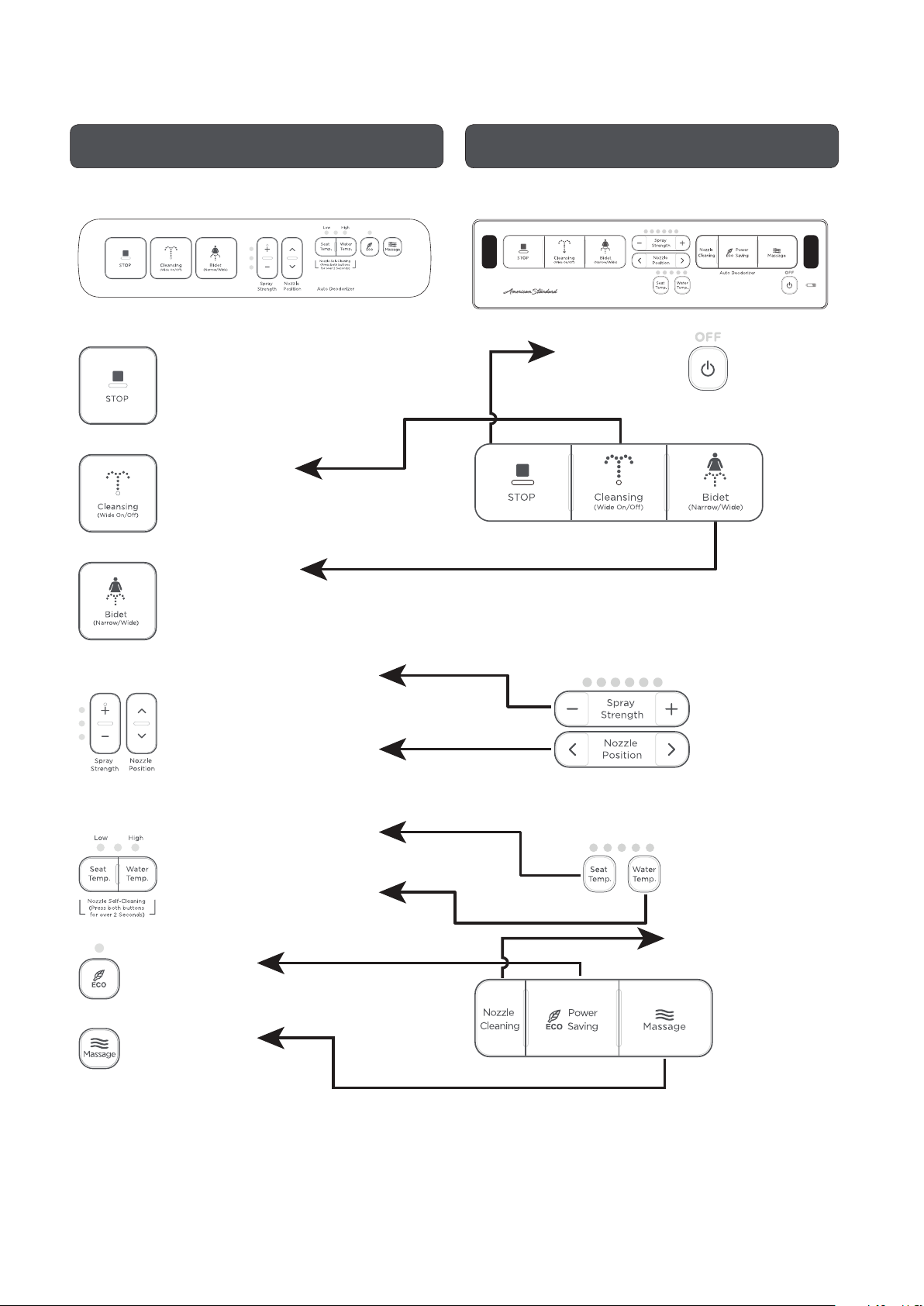
Operating Panel
Remote
STOP
Stops cleansing
functions
CLEANSING
Use for Posterior
Side Panel
Cleansing.
SPRAY
STRENGTH
Adjusts Feminine
and Posterior
spray strength
BIDET
Use for Feminine
Cleansing.
NOZZLE
POSITION
There are 5 modes
for nozzle position
adjustment
SEAT
TEMPERATURE
Adjusts seat
temperature
ECO
Power saving
WATER
TEMPERATURE
Adjusts water
temperature
POWER
Controls POWER
to the seat
MASSAGE
Massage cleaning
(only for posterior)
POWER
Controls POWER
to the seat and
stops cleansing
functions
SPRAY
STRENGTH
Adjusts Feminine
and Posterior
spray strength
10
NOZZLE
POSITION
There are 5 modes
for nozzle position
adjustment
ECO
Power saving
Page 11
Installation
1. Required tools
Have the following tools for installing this product:
adjustable end wrench, Phillips head screwdriver,
flat-blade screwdriver.
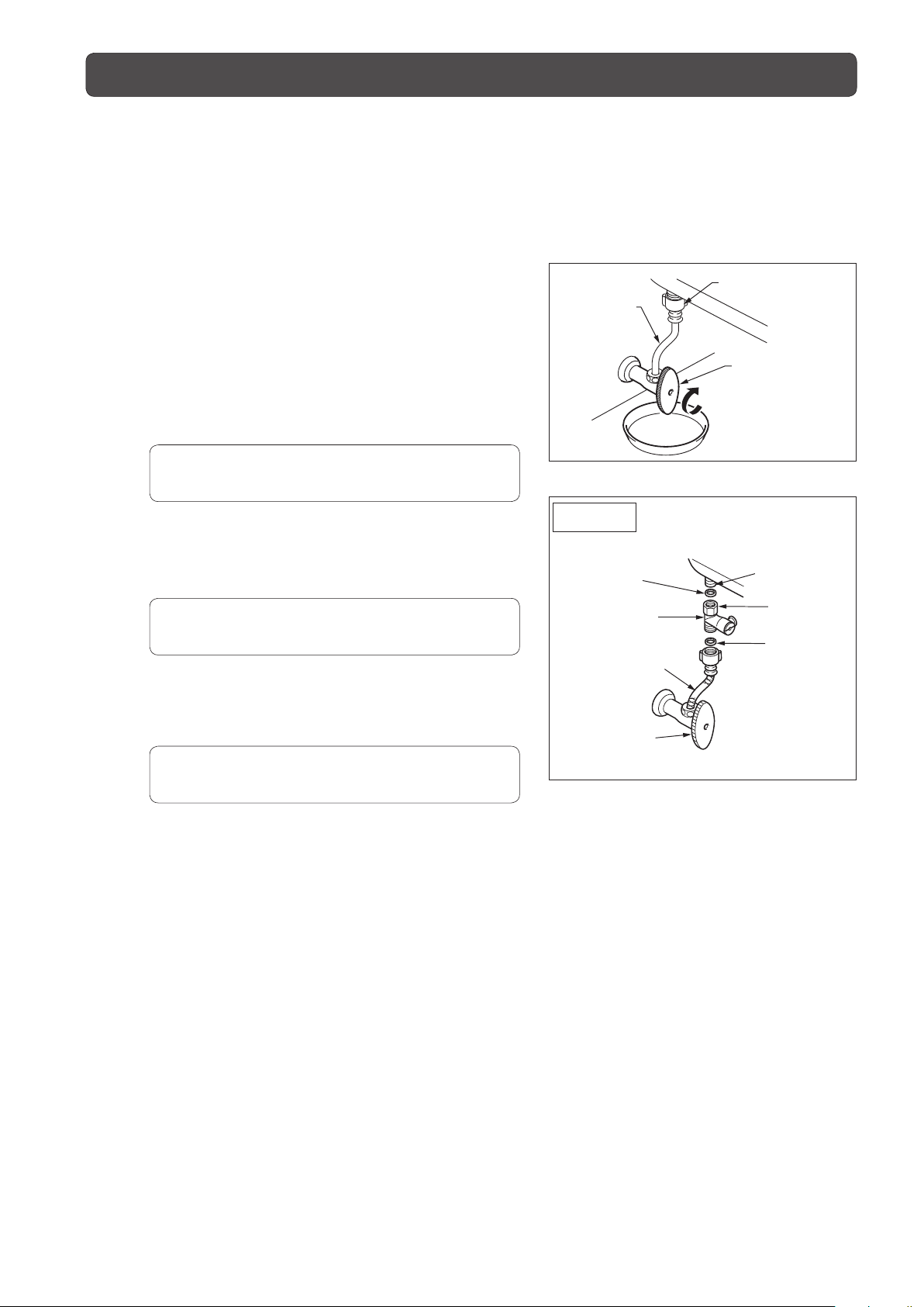
2. Install the junction fitting
1) Close the toilet water shutoff valve fully.
2) Flush the toilet and empty all the water from the
tank.
3) Place a wash bowl or other container
underneath the tank water supply hose. Then
loosen the box nut on the tank inlet side and
remove it.
CAUTION
•
Be careful not to damage the water supply hose.
4) Place the packing in the junction fitting box nut
and connect the tank inlet to the junction fitting.
CAUTION
•Donotovertightenthenut.
5) Insert the packing in the tank water supply hose
box nut and connect the tank water supply hose
to the junction fitting.
Tank Water
Supply Hose
Installation
Figure
Packing
Junction
Tank Water
Supply Hose
Water Shutoff
Bowl Cock Side
Box Nut
Water Shutoff Valve
Close
Tank Inlet
Box Nut
Fitting
Packing
Valve
CAUTION
•Donotovertightenthenut.
11
Page 12
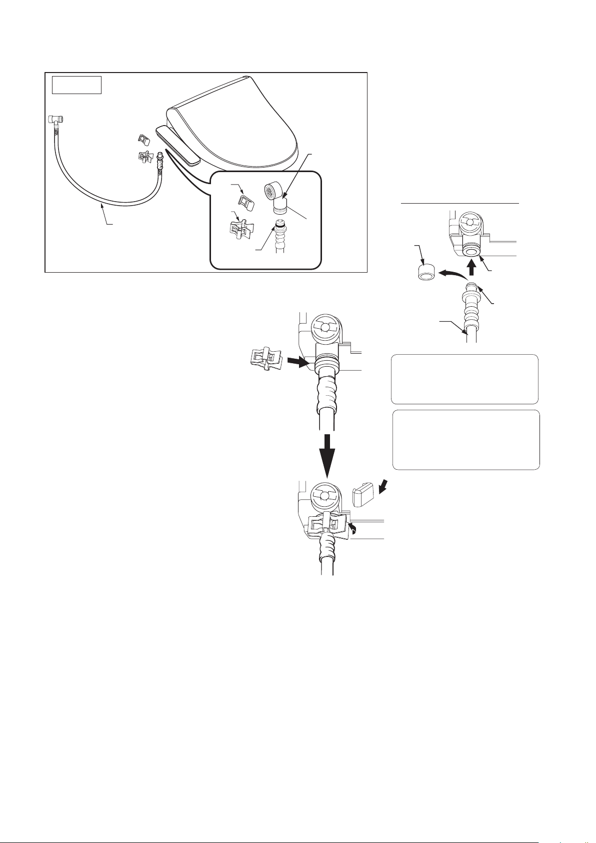
3. Installation of water supply hose to the bidet
1)
Installation
Figure
Remove the protective cover
from the end of the water supply
hose, and pull out the cap from
the water supply connection
socket.
Plastic
Clip
Clip
Water supply
hose
3) Insert the attachment clip onto the
water supply hose to attach it to the
bidet and water supply connection
socket.
* The attachment clip can be attached in
any direction.
O-ring
Water supply
joint
2) Connect the water supply hose
for the bidet to the water supply
connection socket.
WATER SUPPLY
CONNECTION SOCKET
Protective
Cover
Water
supply
socket
Water supply
hose for
O-ring
the seat
CAUTION
•
Be careful not to damage the O-ring.
* A damaged O-ring may cause water to leak.
CAUTION
•Firmlyinserttheclip.
* If the clip is not rmly inserted,
it may cause water leaks.
4) Bend the clip end and firmly clip
together both the feeding hose for
the bidet and the feeding socket.
After you install the clip, twist it in
both directions to verify that it is
firmly attached, then attach the
final attachment clip over the
primary clip to secure in place.
5) Insert the clip until you feel the clip
edge click.
* If not firmly inserted, it may cause
water leaks
12
Page 13
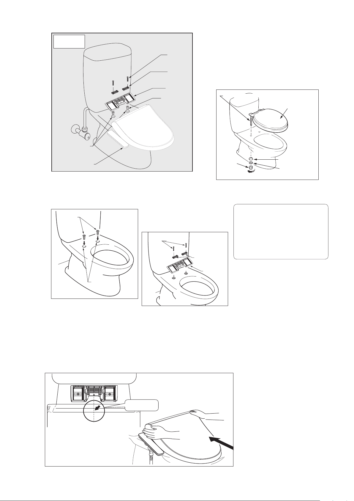
4. Installation of the bidet
Mounting bolts
for the toilet
Mounting
brackets
Mounting plate
Installation
Figure
Body
mounting
bolt
Bracket
Mounting
plate
Bushing
Seat
mounting hole
E-bidet
(2) Install the slide plate onto the seat.
1) Insert the bushings into
the seat mounting holes.
Bushings
2) Insert the mounting
bracket into the mounting
plate and use the mounting
bolts to attach the slide
plate to the seat.
(1) Remove the existing seat.
1) Remove the nuts from the seat
mounting bolts, the slip washers,
and rounded packing.
2) Raise the seat and remove it by
lifting the seat mounting bolts.
Seat mounting bolts
Existing seat
Nut
Loosen
Rounded packing
Slip washer
References
•Sometoiletseatsmayrequire
different methods of removal that
differ from our explanation.
Seat mounting
holes
(3) Install the bidet.
1) Place the bidet on the toilet and align the seat to the
mounting plate.
2) Slightly raise the front side of the bidet, slide it until the
slide plate is fully inserted, and then press the locking
lever to secure the bidet.
Center aligned
13
Page 14
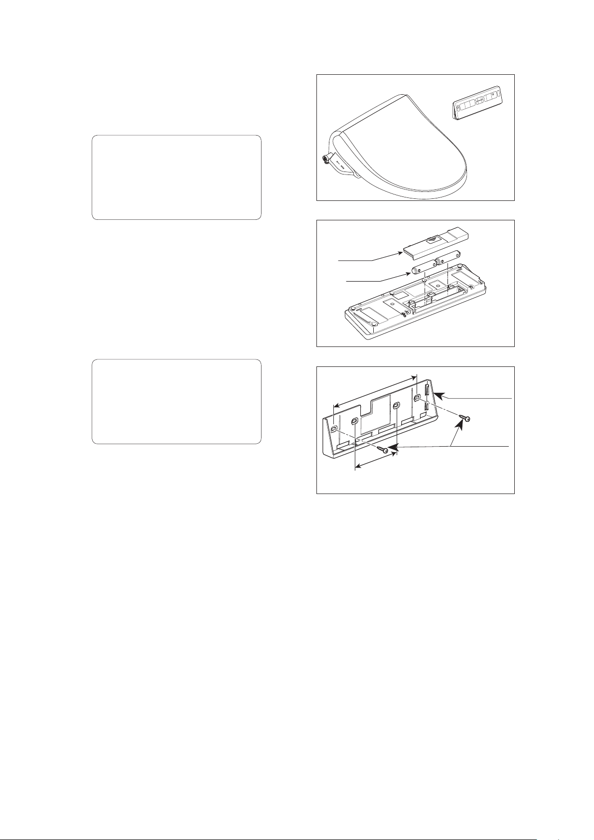
5. Install the remote control unit
* For Remote Version Only
(1) Open the back cover of the
remote control unit and insert the
2 size AA batteries.
CAUTION
• Insert each battery so its positive
pole touches a positive connector
in the battery compartment and its
negative pole touches a negative
connector.
(2) Position the bracket on the wall
in the location you chose for
the remote control unit. Mark the
location of the mounting holes on
the wall. Fasten the bracket to the
wall, drilling holes and using the
fasteners appropriate for the wall
material, as described below.
Back Cover
Battery
CAUTION
• Leave enough space above the
top of the remote control unit to
allow the unit to be removed and
replaced.
If mounted in plywood paneling
0.20 in. (5 mm) or greater in
thickness:
Fasten the bracket to the wall with the
mounting screws.
200mm
100mm
Bracket
Mounting Screw
14
Page 15
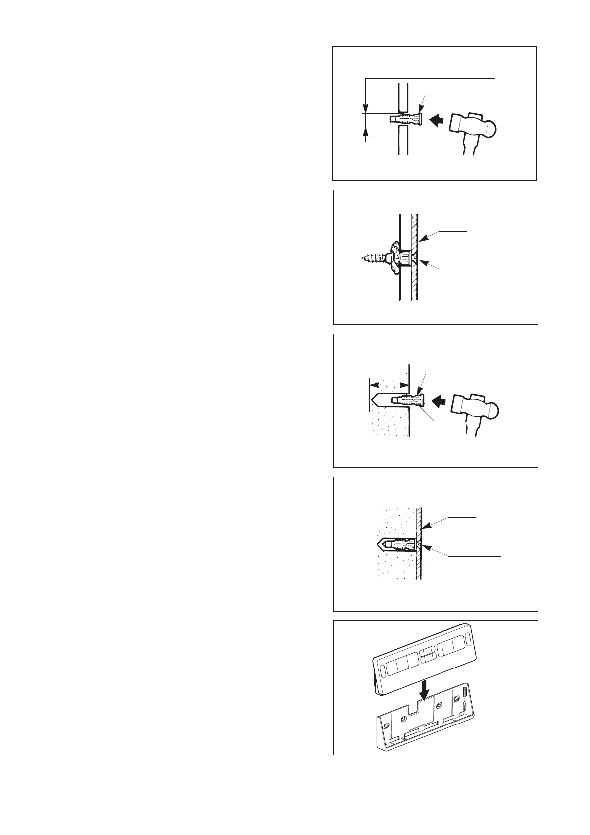
If mounted either in plywood
paneling 0.20 in. (5 mm) or less in
thickness or in gypsum board:
1) In plywood paneling, drill holes with a
diameter of 0.24 in. (6 mm); in gypsum
board, drill holes with a diameter of 0.20
in. (5 mm):
2) Using a hammer, gently drive the
plastic anchors into the holes.
3) Fasten the bracket securely to the
anchors using mounting screws. As you
tighten the screws, they are hard to turn
at first, then gradually get easier to turn,
and then are hard to turn again.
Plywood paneling : 0.24 in. (6 mm)-dia.
Gypsum board : 0.20 in. (5 mm)-dia.
Plastic Anchor
Bracket
Mounting Screw
If mounted in concrete:
1) Drill holes with a diameter of 0.24 in.
(6 mm) and a depth of approximately
1.30 in. (33 mm).
2) Using a hammer, gently drive the
plastic anchors into the holes.
3) Fasten the bracket securely to the
anchors using mounting screws.
1.30 in.
(33 mm)
Plastic Anchor
0.24 in.
(6 mm)-dia.
Bracket
Mounting Screw
(3) Align the remote control unit with the
bracket and then push it down onto the
bracket.
Remote
Bracket
15
Page 16
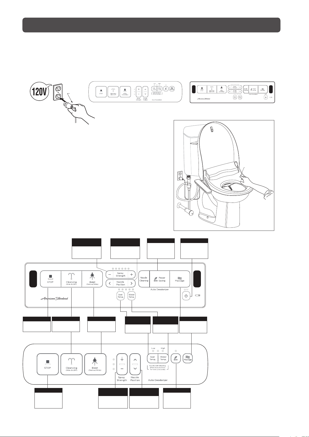
Operational Check
Operational Check
Follow the procedure below after the installation work has
been completed.
1. Insert the power plug into the outlet.
Confirm that the LED on the seat unit is lit.
Power
plug
2.Check the Feminine and
Posterior cleansing spray.
(1) Check the cleansing operation.
1) With your forearm resting on the toilet seat, press the
cleansing button.
The shower automatically stops two minutes after the
switch is turned on.
2) When the nozzle extends, cover the tip of the nozzle
with your hand to catch the spray.
3) Press the STOP button to stop the cleansing spray.
Remote Control VersionSide Panel Version
Press here
on seat
(2) Perform the same check using the
front cleansing spray function.
SPRAY
STRENGTH
Adjusts feminine
and posterior
Remote
STOP
Stops cleansing
functions
CLEANSING
Use for posterior
cleansing.
spray strength
Use for feminine
Side Panel
BIDET
cleansing.
NOZZLE
POSITION
There are 5 modes
for nozzle position
adjustment
SEAT
TEMPERATURE
Adjusts seat
temperature
ECO
Power saving
WATER
TEMPERATURE
Adjusts water
temperature
POWER
Controls power
to the seat
MASSAGE
Massage cleaning
(only for posterior)
POWER
Controls power
to the seat and
stops cleansing
functions
SPRAY
STRENGTH
Adjusts feminine
and posterior
spray strength
NOZZLE
POSITION
There are 5 modes
for nozzle position
adjustment
16
ECO
Power saving
Page 17

OPERATIONAL MANUAL
TABLE OF CONTENTS
Additional Important Information.....................................................................................18
Product Functions .......................................................
Side Panel / Remote Control...........................................................................................19
Preparations Before Use ...........................................................................
How to Use the Basic Functions
How to Use the Convenient Functions
................................................................
...........................................................................
....
......................19
.............
....................
........20
21
24
Maintaining This Product ......................................................................28
Cleaning the Seat Unit.........................................................................
Cleaning the Nozzles..................................................................................................... 28
Changing the Nozzle Tip ................................................................................................ 28
Cleaning & Maintenance of the Deodorizing Screen..................................................... 29
Cleaning the Inlet Strainer ..............................................................................................30
Cleaning Areas Covered by the Toilet Seat Lid & Unit............................................
Change Batteries for the Remote Control .......................................................................32
Troubleshooting .............................................................
Specifications .............................................................................
Warranty information & After-sales Support ..............................
..........
................28
.....
..................33
.....
...
......35
......
.....31
...36
17
Page 18
Additional Important Information
•Thecapacityofthewarmwatertankis0.88L.
Water temperature gradually drops when rear
cleansing or front cleansing is used. If the water
drops below a comfortable temperature, press
the stop button and wait about 3 minutes for the
water to reheat.
•Thewatertemperaturerangeispresettothe
following temperatures:
Low: Approx. 90 °F (32 °C),
Medium: Approx. 93 °F (34 °C),
High: Approx. 97 °F (36 °C).
It takes approximately 10 minutes to heat cold
water (at about 41 °F [5 °C]) to the appropriate
temperature (about 100 °F [38 °C]).
This product is designed to use the tap water
pressure to extend the nozzles and spray water
through them. When the tap water pressure is
extremely low, the nozzles may not spray water
at all when the water pressure is set to the
lowest setting. If this occurs, adjust the Spray
Strength.
Before and after cleansing and when the water
temperature adjustment button is pressed, etc.,
water is sprayed from the nozzle. This occurs by
design and is not a cause for concern.
If water sprays while under any other
configuration, or sprays constantly, close the
water shutoff valve and remove the power plug
from the wall outlet. Then, contact cutomer
service.
This product is equipped with a seat sensor that
prevents the water from spraying if nobody is
sitting on the toilet seat. This prevents activation
if the Bidet button is pressed when the toilet seat
is unoccupied.
When the toilet is new, a slight odor may come
from the deodorizer. This will go away in a short
time.
18
Page 19
Product Functions
Side Panel
STOP
Power On/Off
Stop function
CLEANSING
For posterior cleansing only.
Press twice for oscillating function.
BIDET
For feminine cleansing.
Press twice for oscillating function.
Press twice for super oscillating function.
Remote
STOP
Stop function
POWER
Power On/Off
SPRAY STRENGTH
Adjusts spray strength for
cleansing and bidet settings.
NOZZLE POSITION
Nozzle position adjustment
for optimal cleansing.
SEAT TEMPERATURE
Adjust warm seat temperature
WATER TEMPERATURE
Adjust warm water temperature
ECO
Power saving Mode
MASSAGE
Massage cleaning
(only for posterior)
NOZZLE CLEANING
Nozzle self-cleaning.
FOR DETAILED FUNCTIONS SEE OPERATION SECTION
19
Page 20

Press the STOP button to turn the power ON or OFF.
*
If the power is ON, the power LED on the indicator panel will light up.
be on.
STOP
(Turning the power on/off)
Performing the following operations before using the bidet allows you to use
the toilet comfortably.
Adjust the temperature of the toilet
seat using the Seat Temp. switch.
Adjust the temperature of the bidet
using the Water Temp. switch.
For Side Panel:
The water temperature can be set to one of 3
settings: HI, MID and LO.
For Remote Control:
The water temperature can be set to one of 5
settings
Set it to your preferred temperature.
* The indicator LED cycles through the temperature
settings each time the temperature button is pressed.
* The indicator LED stays on to indicate water
temperature level.
* 2 additional settings above default, for side panel only
For Side Panel:
The seat temperature can be set to one of 3
default settings: HI, MID and LO.
For Remote Control:
The seat temperature can be set to one of 5 settings.
Set it to your preferred temperature.
* The indicator LED cycles through the temperature
settings each time the temperature button is pressed.
* The indicator LED goes out after several seconds.
* 2 additional settings above default, for side panel only
• The toilet seat will not become warm instantly. To achieve
a comfortable seat temperature, set the seat to the desired
temperature about 10 to 15 minutes prior to use.
• This product is equipped with an ECO function that
automatically switches the seat heater off when it is
not occupied.
• The default setting for the seat temperature is "MID". The seat
temperature can be increased or decreased incrementally.
Reference
Preparations Before Use
Seat Temp.
Remote Control
Side Panel
Water Temp.
20
Page 21

How to Use the Basic Functions
Cleansing
Water is sprayed from the posterior
cleansing nozzle.
Press the Cleansing button.
1
Side Panel
Press the STOP button to stop
3
the spraying.
Bidet
Water is sprayed from the feminine
cleansing nozzle.
Press the Bidet button.
1
Press the [+] or [-] Spray Strength
2
button to adjust the shower strength.
* An automatic self-stop function is included
which stops both rear and front cleansing
automatically after 2 minutes.
Remote Control
For Panel Control:
There are 3 levels of spray strength.
For Remote Controlt:
There are 6 levels of spray strength.
Adjust the spray strength as desired.
* The indicator LED cycles through the spray strength
settings each time the button is pressed.
* The indicator LED goes out after several seconds
2 additional settings above default: press STOP and
CLEANSING buttons simultaneously for 2 seconds.
Press here
on seat
21
Page 22

Massage Cleansing
Water pressure alternates between high and low during rear cleansing, providing a massaging effect.
Side Panel
Press the Massage button during
posterior cleansing.
1
Remote Control
To stop the massage spray, press
the Massage button again.
2
22
Page 23

Deodorizing
Deodorizing starts when a person
1
sits on the toilet seat.
*
This product is equipped with a deodorizer cartridge which
absorbs odors from the toilet.
Deodorizing automatically stops
2
after you stand up.
Stops after 5 seconds
To disable the deodorizer
Press the STOP and Bidet buttons
simultaneously for 2 seconds.
*
When the deodorizer feature is disabled, the power
LED on the seat unit flashes momentarily. At this
point, the deodorizer will no longer activate when a
user is detected.
* The restore the deodorizer function, press the
STOP and Bidet buttons simultaneously for
2 seconds.
Only for Side Panel
Press the buttons simultaneously for 2 seconds.
Only for Remote Control
23
Page 24

How to Use the Convenient Functions
ECO button
One-Touch Power Save: Reduces power consumption by turning off the water and seat heater for 8 hours.
.sruoh 8 retfa derotser yllacitamotua era sgnittes rewop ehT
One-touch power save (8 hours)
Press the ECO button.
For side panel, the power save ECO LED
1
lights up.
For remote control, the power save ECO LED
lights up on the seat next to the power LED.
Only for Side Panel Only for Remote Control
Only for Side Panel
For example: when one-touch power save is set for 10:00
Water/Seat Temperature
Customer Set
Temperature
Power Save
Temperature
OFF
8:00
Set
10:00
12:00 2:00
8 hours
4:00
Reheat
6:00
8:00
10:00 12:00
* For Side Panel:
When the One-Touch Power
Save function is running,
the ECO LED lights up.
* For remote control:
the ECO LED lights up
on the seat
Only for Remote Control
* Once 8 hours have passed, the power settings will automatically return to their original state. The power
ashing to off.
*
The one-touch power save is not automatically repeated everyday, but can be set any number of times in a day.
To cancel the ECO mode function, press
the ECO button again.
2
(The ECO power save LED will go out.)
* You can use the toilet even when the ECO save function is operating. However, you may feel that
the water is cold as the heater for water and the toilet seat is turned off. If desired, you may turn off
the ECO save function.
* Even when the ECO save function is not operating, leaving the toilet lid closed is an effective way to
conserve energy.
24
Page 25

High Efficiency Power Savings
When the product is not in use, it lowers the temperature of warm water and seat to control
power consumption until the product is put back into use.
Press [Water Temp] and [Power Saving] button, and hold for 2 seconds or more.
Power saving indicator flashs once activated.
SET
Warm WaterSeat Temperature
Setting
Temperature
Power Saving
Temperature
OFF
OFF
In Use
BACK
Flash 2 times
per second
Power
Saving
How to cancel high efficiency power saving function
Press [Water Temp] and [Power Saving] button, and hold for 2 seconds or more.
Power saving indicator of displayed part turns off.
(Reference)
When the unit is in the Power Save mode, the temperature of the water and seat will start out a bit cool,
but will warm up while in use.
Even when the Power Saving function is not operating, leaving the toilet lid closed is an effective way
to conserve energy.
25
Page 26

Other convenient functions
(For side panel version of bidet seat only)
Seat Temp. expand from 3 to 5 modes
Press Seat Temp. and Nozzle position UP (arrow up) for
2 seconds to expand the seat temperature adjustments
from 3 to 5 modes.
• Aftersetting,allindicatorswillashonce.
• TheLowandMidindicatorwillbothlightupwhenseat
temperature is in the middle of Low and Mid.
Mid and High indicator will both light up when seat
temperature is in the middle of Mid and High temperature.
Resume initial setting
Press Seat Temp and Nozzle Position UP for 2 seconds.
• Aftersetting,allindicatorswillashonce.
* The seat heater automatically turns ON when you stand up.
Water Temp. expand from 3 to 5 modes
Press Water Temp. and Nozzle position DOWN (arrow down)
for 2 seconds to expand the water temperature adjustments
from 3 to 5 modes.
• Aftersetting,allindicatorswillashonce.
• TheLowandMidindicatorwillbothlightupwhenwater
temperature is in the middle of Low and Mid.
Mid and High indicator will both light up when water
temperature is in the middle of Mid and High temperature.
Indicator
Indicator
3 modes
Seat temp.
Low Low
Mid Low mid
High Mid
3 modes
Warm Water temp.
Low
Mid
High
Indicator
Indicator
5 modes
Seat temp.
Mid high
High
5 modes
Warm Water temp.
Low
Low mid
Mid
Mid high
High
Resume initial setting
Press Water Temp. and Nozzle Position DOWN for 2 seconds.
• Aftersetting,allindicatorswillashonce.
Spray Strength expand from 3 to 5 modes
Press Water Temp. and Spray Strength " "
for 2 seconds to expand the spray strength
adjustments from 3 to 5 modes.
• Aftersetting,allindicatorswillashonce.
• TheLowandMidindicatorwillbothlightupwhenspray
strength is in the middle of Low and Mid ow.
Mid and High indicator will both light up when spray
strength is in the middle of Mid and High ow.
Resume initial setting
Press Water Temp. and Spray Strength " " for 2 seconds.
• Aftersetting,allindicatorswillashonce.
Press the buttons simultaneously for 2 seconds.
3 modes
Indicator Spray Strength Indicator Spray Strength
Low
Mid
High
5 modes
Low
Low mid
Mid
Mid high
High
26
Page 27

If freezing weather or long term absence is
Turn clockwise.
anticipated, drain the water.
(1) Turn the water shutoff valve clockwise to shut off the
water supply to the tank.
(For draining in cold areas, operate the indoor drain plug.)
(2)
Press the flush lever on the tank to drain water from the tank.
(3) Remove the power plug from the outlet.
(4) Drain the water from the warm water tank and the water
supply hose connected to the seat unit.
(5)
Push the lock lever on the right side of the seat unit and slide the
seat unit forward to remove it from the toilet bowl.
(6)
Remove the strainer located on the left side of the seat unit. Place
a wash bowl or similar item underneath the strainer.
(7) Tilt the seat unit to the left to drain the water from the water
supply hose through the strainer hole.
(8)
After the water has been drained, firmly attach the strainer.
(9)
Turn the drain plug located on the bottom of the seat unit to the
left (counterclockwise) 90 degrees to loosen it.
(10) Tilt the seat unit forward, pull out the drain plug and completely
drain out the water from the warm water tank.
(11)
After the water has been drained, push and turn the drain plug
to the right (clockwise) 90 degrees to tighten it.
(12) Place the seat unit on the toilet bowl. Slide the seat unit
backward to secure the seat unit.
Lock Lever
Strainer
CAUTION
When removing the strainer,
be sure to close the water
shutoff valve. When attaching
the strainer, firmly tighten it
until the end of the strainer
is hidden in the seat unit.
* Water can leak from
the strainer.
End
Warm Water Tank Drain Plug
Right side of seat unit
* Remove the warm water tank drain plug when
draining the water from the warm water tank
27
Drainage Valve of
warm water tank
.
Page 28

Maintaining This Product
Cleaning the Seat Unit Cleaning the Nozzles
Periodically, wipe off the seat unit with
a soft cloth dampened with water.
a) Bidet Seat must be powered ON to clean
nozzle tip.
b) For side panel type, under non-seated
situation to clean nozzles manually, press
"Seat Temp" and "Water Temp" buttons at the
same time for over 2 seconds.
For remote type, under non-seated situation
to clean nozzles manually, press "Nozzle
Cleaning" button for over 2 seconds.
c) Grasp the nozzle tip and pull out. Use a soft
sponge to clean any accumulated debris.
Changing Nozzle Tips
a) Ensure bidet is powered ON.
b)
For side panel type, under non-seated situation to clean
nozzles manually, press "Seat Temp" and "Water Temp"
buttons at the same time for over 2 seconds.
For remote type, under non-seated situation
to clean nozzles manually, press "Nozzle
Cleaning" button for over 2 seconds.
c) Grasp the nozzle tips and pull out.
d) Push new tips onto the nozzle ends.
28
Page 29

Cleaning & Maintenance of the Deodorizing Screen
Cleaning the Deodorizing Screen
1. Disconnect the power plug from the outlet
and shut off the water supply at the valve.
2. Remove the seat from the toilet.
3. Pull the screen from under the left hand
side of the seat.
4. Remove the dirt from the screen using a
toothbrush or other small brush.
5. Install the strainer back into the base
plate of the toilet seat.
6. Install the seat back onto the bowl.
7. Plug the seat back into the power outlet.
29
Page 30

Cleaning the Inlet Strainer
If the water pressure weakens over time, clean the strainer using the following procedure.
Cleaning the Inlet Strainer
1. Close the water shutoff valve to cut off
the water supply.
NOTE: Since the water shutoff valve is adjusted
beforehand, keep track of the turns so that you can
return to the original position.
2.
Turn the strainer located on the bottom
left of the seat unit using a screwdriver or
similar tool and remove it.
When the strainer is removed, a small amount of water
will pour out. Place a wash bowl or similar container
underneath to catch the water.
Strainer
Turn counterclockwise.
3. Remove the dirt adhering
to the inside of the strainer
by rinsing it with water.
4. Install the strainer, tightening it fully with a
screwdriver or similar tool.
End
Tighten the strainer until
the end is completely
inside the seat unit.
5. Open the water shutoff valve by turning
the water shutoff valve back to its original
position.
6. Finally, perform an operational check.
30
Page 31

Cleaning Areas Covered by the Toilet Seat Lid & Unit
Turn clockwise.
Water
shutoff valve
Slide
forward
Lock lever
3a
3b
Slide
forward
Wipe o here.
CAUTION
When cleaning this product, be sure to unplug the power plug from the wall outlet.
Removing the toilet seat lid
1. Move the pin hole on the right side
of the toilet seat lid to the outside and
remove it from the pin.
Toilet seat lid
Move to the outside.
Pin hole
Pin
2. Hold the toilet seat up on the right
side and slide it to the left, removing it
from the pin on the left side.
CAUTION
If you try to pull hard to remove the toilet seat
lid, it could crack or break.
Slide
Lift up
Removing the seat unit
3a. Push the lock lever on the right side of the seat unit.
1. Remove the power plug from the
wall outlet.
2. Close the water shutoff valve to
cut off the water supply.
4. Carefully place the seat unit on the rim of the
toilet bowl.
5. To reinstall seat, slide it back on mounting pad.
3b. Pull from base of seat, slide the seat forward by grasping at base,
raise it slightly and remove from toilet.
* When removing this
product, slide the unit
slowly without holding
the toilet seat or toilet
seat lid. Do not use
excessive force.
CAUTION
When cleaning the toilet bowl, take care not to splash
the seat unit with detergent. Before installing the seat
unit, wipe the detergent off from the toilet bowl using a
cloth damped with water.
31
Page 32

Change Batteries for the Remote Control
When batteries are about to run out, the battery indicator LED
display begins to flash.
The indicator only flashes when batteries are low.
The batteries included were used in testing of product and
may not have the normal lifecycle.
The lighting in the room area may make it difficult to see
the low battery LED flashing.
Change new batteries for the remote control; as follows.
Cautions
The + and - of the battery shall comply with the marks on the remote control
Do not mix the new battery with the used ones.
Use alkaline batteries.
Do not touch the switches or buttons on the remote control when
changing batteries.
Change Batteries for the Remote Control
Pull the remote control up and
take it out from the bracket.
Remote
Control
Bracket
Open the rear cover of the battery
compartment and place 2-AA batteries
e
Buckle
Alkaline Dry
Battery
Rear
Cover
Place the cover back and the remote control into the bracket.
32
Page 33

Troubleshooting
You can easily correct some of the problems with this product. Before requesting repairs, please check the
following items.
If you are unable to correct the problem using the troubleshooting procedures shown below, please contact
your local customer service representative.
All functions
Symptom
The system will not operate
at all.
Electricity is not being supplied to
the power outlet.
The power switch is off. The LED
on the indicator panel is off.
The power plug is not plugged into
the wall outlet.
Cause
Check for a power failure or tripped breaker,
etc.
Press the STOP button for 2 seconds to verify
the LED lights on the seat unit light up.
Plug the power plug into the wall outlet.
Posterior cleansing and Feminine cleansing
Symptom
The water shutoff valve is closed. Turn the water shutoff valve counterclockwise.
Cause
Remedy
Remedy
Water does not
spray out.
Symptom
Spray water is not warm.
The inlet strainer is clogged. Clean the inlet strainer.
Tap water pressure is low. Spray
strength is set to “Lo”.
The seat sensor is not engaged. Sit back fully on the toilet seat.
Cause
Water temperature is not set to an
appropriate temperature.
The Cleansing or bidet function
was used for a long period of time.
ECO mode is activated. Disable ECO mode.
Set the spray strength to a higher level.
Remedy
Adjust the water temperature to the
appropriate level.
The water takes about 3 minutes to warm
back.
33
Page 34

Heated Toilet Seat
Symptom
The toilet seat is not warm.
Others
Symptom
The seat unit becomes
loose
Cause
Seat temperature is not set to an
appropriate level.
ECO mode is activated. Disable power save.
Cause
The seat unit is not locked. Push the seat unit until it locks in position.
Adjust the seat temperature to the appropriate
level.
Remedy
Remedy
WARNING: A damaged or overheated power plug or cord, or a loose or overheated wall
outlet, could cause injury or damage the product. If this occurs, remove the
power plug from the wall outlet, contact us, and discontinue using this product
until the situation has been corrected.
34
Page 35

Specifications
Product Type Remote Control Side Panel Control
Rated Voltage AC120V 60Hz
Rated Power 300W±10%
Inlet Water
Pressur Range
Ambient Temperature Range 32°F~104°F (0°C~40°C
Min. 9 psi (0.06MPa) Flow pressure
Max. 108 psi (0.75MPa) Hydrostatic pressure
Cleansing
Remote
Heated
Seat
Deodorizer
Power
Saving
Other
Convinient
Functions
Product Dimension
Water Inlet Type Direct inlet flow
Heating Type Warm water storage tank
Rear Cleansing Volume
Front Cleansing Volume
Water Temperature
One Touch Cleansing
Oscillating
Massage
Nozzle Position
Adjustment
Heating Power 230W±10%
Safety Device Temp.sensor, Temp fuse, High Temp. sensor switch
Dimension
Power Source 2*1.5v AAA batteries
Surface Temperature
Heating Power 57W±10%
Safety Device Temp. sensor, fuse
Deodorizing Method Chemstorption by activated carbon deodorizer
Deodorizing Perfprmance Auto Deodorizing : 3.8CFM (0.11m³/min)
One Touch Power Saving
Super Power Saving
Nozzle Self Clean
Nozzle Manual Clean
Nozzle Shutter
Seat Heating Auto Off
Sitting Sensor
Anti-microbial Material
L 21-1/16" x W 17-3/16" x H 6-7/8"
(L 536mm*W 436mm*H 173mm)
0.42~1.27 pint/min (0.25~0.6L/min)
(6 adjustment levels)
water pressure 29psi (0.2 Mpa)
0.96~1.27 pint/min (0.45~0.6L/min)
(6 adjustment levels)
water pressure 29psi (0.2 Mpa)
OFF (Water temperature) Low-about
90°F (32°C); Relatively Low-about 93°F
(34°C); Mid-about 97°F (36°C); Relatively
High-about 100°F (38°C); High-about
104°F (40°C)(5 adjustment levels)
(Rear cleansing only)
•
L263mm*W32.5mm*H71mm
L10-3/8"*W1-1/4"*H2-13/16"
Room temperature/ about 82°F - 104°F
(28°C—40°C) 5 adjustable levels
Nozzle, Seat, Side control panel/ Remote control panel
L 21-1/16" x W 18-9/16" x H 6-7/8"
(L 536mm*W 472mm*H 173mm)
0.42~1.27 pint/min (0.25~0.6L/min)
(3/5 adjustment levels)
water pressure 29psi (0.2 Mpa)
0.96~1.27 pint/min (0.45~0.6L/min)
(6 adjustment levels)
water pressure 29psi (0.2 Mpa)
OFF (Water temperature)
Low-about 90°F (32°C);
Mid-about 97°F (36°C);
High-about 104°F (40°C)
(3/5 adjustment levels)
•
•
•
Room temperature/ about 82°F - 114°F
(28°C—40°C) 3/5 adjustable levels
(8hr)
•
•
•
•
•
•
•
—
Soft Close Seat & Cover
Quick Detach Cover
Quick Detach Main Body
•
•
•
35
Page 36

For residents of the United States, warranty
information may also be obtained by calling
AS AMERICA, INC. ONE YEAR LIMITED WARRANTY
If inspection of this AS America, Inc. (“American Standard”) plumbing product, within one year after its initial
purchase, confirms that it is defective in materials or workmanship, American Standard will repair or, at its
option, exchange the product for a similar model.
This limited warranty applies only to the original purchaser and installation of these products. In the event of a
limited warranty claim, proof of purchase will be required—save sales receipt.
This limited warranty does not apply to local building code compliance. Since local building codes vary
considerably, the purchaser of this product should check with a local building or plumbing contractor to ensure
local code compliance before installation.
This limited warranty is void if the product has been moved from its initial place of installation; if it has been
subjected to faulty maintenance, abuse, misuse, accident or other damages; if it was not installed in accordance
with American Standard's instructions; or if it has been modified in a manner inconsistent with the product as
shipped by American Standard.
American Standard's option to repair or exchange the product under this limited warranty does not cover any
labor or other costs of removal or installation. IN NO EVENT WILL AMERICAN STANDARD BE LIABLE FOR
THE COST OF REPAIR OR REPLACEMENT OF ANY INSTALLATION MATERIALS, INCLUDING BUT NOT
LIMITED TO, TILES, MARBLE, ETC. American Standard will not be responsible for any other incidental or
consequential damages attributable to a product defect or to the repair or exchange of a defective product, all
of which are expressly excluded from this limited warranty. This limited warranty does not cover any liability for
consequential or incidental damages, all of which are hereby expressly disclaimed, or the extension beyond the
duration of this limited warranty of any implied limited warranties, including those of merchantability or fitness
for an intended purpose. (Some states or provinces do not allow the exclusion or limitation of implied limited
warranties, so this exclusion may not apply to you.)
This limited warranty gives you specific legal rights. You may have other statutory rights that vary from state to
state or from province to province, in which case this limited warranty does not affect such statutory rights.
In the United States:
American Standard Brands
1 Centennial Ave.
Piscataway, New Jersey 08854
Attention: Director of Customer Care
In Canada:
AS Canada, ULC
5900 Avebury Rd.
Mississauga, Ontario
Canada L5R 3M3
Toll Free: (800) 387-0369
www.americanstandard.ca
In Mexico:
American Standard B&K Mexico
S. de R.L. de C.V.
Via Morelos #330
Col. Santa Clara
Ecatepec 55540 Edo. Mexico
Toll Free: 01-800-839-1200
www.americanstandard.com.mx
Page 37

WALK-IN BATH INSTALLATION
INSTRUCTIONS AND OWNER’S MANUAL
Page 38

CONGRATULATIONS!
You are now the owner of a walk-in bathtub from the most trusted name in plumbing.
We thank you for your purchase. Your American Standard ® walk-in bath is a true
investment in your health and peace of mind.
Customer Support: (866) 423-0800
1
Page 39

OWNERS MANUAL
TABLE OF CONTENTS
UNPACKING THE UNIT………………………………………………………………. Page 3
RESPONSIBILITIES OF THE INSTALLER…………………………………………… Page 4
TESTING YOUR TUB BEFORE INSTALLATION…………………………………… Page 5
INSTALLATION PREPARATION…………………………………………………….. Page 6
ELECTRICAL INSTALLATION………………………………………………………. Page 7
INSTALLATION PROCEDURES…………………………… ………………………... Page 8-17
SAFETY INSTRUCTIONS ……………………………… ……………………………. Page 18
OPERATING INSTRUCTIONS…………………………… ………………………….. Page 19-20
CLEANING & MAINTENANCE……………………………………………………..... Page 21
WARRANTY…………………………………………………………………………..... Page 22
TROUBLESHOOTING………………………………………………………………..... Page 23-25
2
Page 40

OWNERS MANUAL
UNPACKING THE UNIT
1. FIRST, inspect the carton for damage: CAREFULLY DOCUMENT AND
PHOTOGRAGH ALL PERCEIVED DAMAGE. Report all damage claims to
customer service at 1-866-423-0800.
2. DO NOT LIFT THE TUB BY THE PLUMBING
which the installer is responsible. All Walk-In Tubs are water tested before they
leave our factory and the bathtub you have purchased has passed inspection.
3. Immediately inspect the unit for damage even if there is no carton damage. All
product damage must be reported within 72 hours of receipt from American
Standard®. Once the unit is installed, surface damages will be assumed to be
installation-related if not reported prior to installation. Installers are also responsible
for damage that occurs once the unit is placed in its niche.
NOTE: Remove all packaging material except for the protective plastic. This has
been placed on the tub at the factory to eliminate abrasions from handling. This
should only be removed at final clean up.
4. Inspect the plumbing for any fittings that may have loosened in transit.
5. Read the following instructions completely before installing this product. If the
home-owner or installer has any questions, please call us at 1-866-423-0800.
6. You must follow all the instructions in this manual.
FAILURE TO READ AND COMPLY WITH ALL INSTRUCTIONS CAN RESULT IN
PRODUCT DAMAGE OR INJURY TO BOTH INSTALLER AND HOMEOWNER. IT
WILL ALSO RESULT IN ASSUMPTION OF ALL LIABILITY BY SAID INSTALLER.
. Doing so can result in leaks, for
3
Page 41

OWNERS MANUAL
RESPONSIBILITIES OF THE INSTALLER
The Installer must inspect and water test the product prior to installation to ensure the unit is free of defect
and /or damage. In the event of a problem, the unit must not be installed. If the packaging or product has
been damaged, please call immediately at 1-866-423-0800.
This product has been listed by INTERTEK / ETL and IAPMO / C UPC. The product has been tested and
complies with the following standards and guidelines: IAPMO /C UPC, UL-1795, ANSI Z-124.1.2,
ASME A 112.19.7, ASME A 112.19.15 & CSA B-45. The installer is responsible for compliance to
state and local codes.
This product is designed to be installed by a licensed tradesperson. Licensed plumbers and electricians
should be employed to insure proper installation. Installer assumes all liabilities for installation
procedures.
Although American Standard® has taken reasonable precautions to ensure that the Quick Drain
suitable for residential plumbing; it is the responsibility of the installer to insure that the plumbing is
acceptable for use of the Quick Drain TM. American Standard® does not accept responsibility for
damage arising from use of the Quick Drain TM.
Only accessories authorized by manufacturer should be used with this product.
TM
is
IMPORTANT SAFETY INSTRUCTIONS
INSTRUCTIONS PERTAINING TO RISK OF FIRE,
ELECTRICAL SHOCK OR INJURY TO PERSONS
SAVE THESE INSTRUCTIONS!
WARNING! ALL INSTRUCTIONS LISTED IN THIS MANUAL SHOULD BE READ AND
FOLLOWED CAREFULLY. ALL PRECAUTIONS PERTAINING TO RISK OF FIRE,
ELECTRIC SHOCK, OR INJURY TO PERSONS MUST BE UNDERSTOOD AND
EXPLAINED TO OWNER.
TO REDUCE THE RISK OF INJURY, CHILDREN OR PERSONS WITH INFIRMITIES
MUST NOT BE PERMITTED TO USE THIS PRODUCT WITHOUT CLOSE AND
CONTINUOUS SUPERVISION.
4
Page 42

OWNERS MANUAL
TESTING YOUR WALK-IN TUB BEFORE INSTALLATION
1. All American Standard® walk-in baths are 100% water tested at the factory and have passed inspection.
Transportation and mishandling may loosen fittings and cause leaks. It is therefore necessary to test the
bathtub while there is access to all sides of the bath.
2. The unit needs to be filled with water and inspected for leaks along the door as well as the whirlpool and
air systems if equipped. The inspection needs to be performed with and without the whirlpool and / or air
systems operating. It is best to test the unit outside by filling with a garden hose.
3. If the pump/blower/lights/heater does not operate:
Failure to perform these tests before installation will make the installer liable for future repair costs.
a. Place the tub on a completely flat surface in an area where it may be drained after testing.
b. Using a clean rag and warm water wipe down seal to insure it is free of debris.
c. Seal the drain hole (this can be done with tape) and fill the tub to at least three inches above the
highest jet, or to the bottom of the safety bar if no jets are present.
d. Allow the water to stand in tub for 30 minutes and then inspect all plumbing and seals for
leaks.
e. Using appropriately rated three-prong extension cords, all plugged in to separate outlets,
operate all electrical components (air blower, water pump, and heater if applicable) for another
30 minutes and inspect for leaks again. Inspect the unions around the pump and heater.
f. If a leak persists at a union after tightening, it may have been over-tightened or might have a
displaced O-ring. Disassemble it and make sure the O-ring was seated properly. Do the same if
a leak persists at the heater. Verify that the heater threads match the pipe threads.
g. Ensure that all jets are open and working, some jets are adjustable for both flow rate and
direction of flow. The jet water flow rate is adjusted by turning either the outside ring or the
inside nozzle clockwise or counterclockwise. Some jets are not adjustable at the jet face, but
can be adjust by the “Leg’s Only Massage”. The “Legs Only Massage” Valve is located near
the seat. (If equipped.) .
a. Check the breaker to ensure that power is on and make sure that any cables and / or air lines
connecting the control boxes to the switches and pumps are firmly attached. Verify the correct
electrical circuit and amps of the electrical cord.
b. Go to Trouble Shooting Guidelines. (See pages 23-25.)
c. Do not
dry operation of pumps is not covered under the warranty period. (See pg. 22.)
run any pumps unless the tub is filled with water to the proper level. Damage due to
5
Page 43

OWNERS MANUAL
INSTALLATION PREPARATION
1. Check the floor area where the tub is to be installed.
a. Clean area of any debris or trash.
b. Use a 5 or 6-foot level and determine if the floor is level. If the floor is not level,
adjust all leveling feet to perfectly level the tub.
Note: It is important that all leveling feet are completely touching the floor and
level for the door system to work properly.
2. Check to ensure that the drain piping has been “roughed-in” at the proper location. See
specification sheets (installation detail) included in this manual.
3. Ensure that the proper electrical service has been installed at the pump location. See electrical
Requirements in the manual. (See page 7.)
6
Page 44

OWNERS MANUAL
ELECTRICAL INSTALLATION
All electrical wiring must be installed in accordance with the National Electrical Code and with all
local codes. All wiring shall be done by a qualified electrician. Run one, two or three branch circuits
(as required) from the main electrical service panel to the pump area of the framing structure to
provide power to the unit.
Electrical components have specific wiring requirements. Refer to the matrix below for the electrical
supply requirements for the whirlpool bathtub and factory installed components.
Branch circuits must be rated for 110 – 120 volts. Use 12 Gauge, 3 conductor cable for the circuits.
If the length run exceeds 100 feet, check with local codes for requirements. Install moisture proof
junction box(s) 6” above the floor at the pump end of the framing for each circuit.
DO NOT INSTALL THE JUNCTION BOX(S) WHERE IT CAN BE REACHED WHILE SITTING OR
STANDING IN THE TUB OR TOUCHING THE FAUCETS.
QUICK DRAIN™, LIGHTS, WHIRLPOOL, AIR SPA, COMBO & HEATER
ELECTRIAL REQUIREMENTS
This section lists the factory installed components of the Whirlpool and/or Air Spa Systems.
Note the required number of circuits and their rating for the Whirlpool & Air Spa unit you are planning to install.
ELECTRICAL REQUIREMENTS FOR FACTORY INSTALLED COMPONENTS
Electrical Rating
Systems
Soaker w / Quick Drain™ 15 Amp GFCI
Soaker w / Light 15 Amp GFCI
Soaker w / Quick Drain™ w / Light 15 Amp GFCI
Whirlpool or Air Spa 15 Amp GFCI
Whirlpool or Air Spa w / Light 15 Amp GFCI
Whirlpool or Air Spa w/ Quick Drain™ 15 Amp GFCI 15 Amp GFCI
Whirlpool or Air Spa w/ Light & Quick Drain™ 15 Amp GFCI 15 Amp GFCI
Whirlpool & Air Spa (Combo) 15 Amp GFCI 15 Amp GFCI
Whirlpool & Air Spa (Combo) w/ Light 15 Amp GFCI 15 Amp GFCI
Whirlpool & Air Spa (Combo) w/ Quick Drain™ 20 Amp GFCI 15 Amp GFCI
Circuit 1
Electrical Rating
Circuit 2
Dedicated
Circuit
Whirlpool & Air Spa (Combo) w/ Light & Quick Drain™ 20 Amp GFCI 15 Amp GFCI
Whirlpool Inline Heater - Dedicated Circuit
All electrical connections must be carried out by a certified electrician in accordance with local electrical
requirements and codes.
15 Amp GFCI
7
Page 45

OWNERS MANUAL
INSTALLATION PROCEDURES
▲ WARNING: When installing whirlpool massage baths, air spa baths, combo baths, or Quick Drain™
equipped baths, the following precautions must be followed:
▲ WARNING: Danger: Risk of electrical shock; connect components to separate circuits, EACH protected
by a ground fault circuit interrupter (GFCI)
▲ WARNING: Installation must provide access for servicing the pump and motor (all American
Standard® walk-in baths come with access panels for the pump, motor and faucet).
1. Install tub waste/overflow according to instructions included with the provided kits. The Gel Coat Series
requires the installation of a door drain with check valve. The check valve and tubing must be installed
horizontal to the floor. Some installations will require the purchase of additional fittings.
2. American Standard Faucet Installation # 9FHS-CH
Review the installation instructions packed with the faucet set.
Mask off the tub’s deck with a protective tape.
Locate and mark the center line of the overflow fitting
Locate and mark 1 ½” line either side of the tub’s center line to establish the overflow clearance.
Follow the drill template and faucet installation instructions.
3. Other Faucet Model and / or Brand
Review the installation instructions packed with the faucet set.
Mask off the tub’s deck with a protective tape.
Locate and mark the center line of the overflow fitting
Locate and mark 1 ½” line either side of the tub’s center line to establish the overflow clearance.
Verify the first two component mounting clearance on either side of the waste overflow as well as
above and below the tub’s deck.
Verify the remaining component mounting clearance on both sides of the overflow as well as above
and below the tub’s deck.
It is recommended the hand held shower be installed on the corner closest to the wall to prevent water
from leaking off the deck and on to the floor.
4. Install the optional in-line water heater per manufacturer’s instructions.
5. Standard Walk-In Bath Installation - After framing is complete, set product in place to check fit and make
certain that the tub can be properly leveled. (Caution: If the bathtub is not resting on all leveling feet, water
will not drain properly and this may cause the door to leak). Secure tub frame to the studs using metal
straps. (Not provided.)
5a. Fire-Rated Drywall – If fire-rated drywall is specified, the finished fire-rated wall must be in place before
the tub is installed. The dimensions of the framing structure must be increased by the thickness of firerated drywall.
8
Page 46

OWNERS MANUAL
INSTALLATION PROCEDURES
WARNING: Never allow the weight of the tub to be supported by wood support stringers and do not use
integral tile flange (if equipped) to screw or nail in place, as this will result in product failure and will
void the warranty.
6. Verify the product is completely level by checking tub deck surface and ensure all leveling feet are
touching the ground.
7. Electrical connection is made by simply plugging each cord into the GFCI outlet.
8. After plumbing and electrical connections have been made, the tub and door seal should be cleaned of dirt
and debris. Use warm water and a non abrasive cleaner for clean up.
9. Installation is not complete until the bathtub has been water-tested in place and does not leak.
9
Page 47

OWNERS MANUAL
g
Alcove Installation
`
Faucet and Pump
Access Panels
IMPORTANT
Do not use tile flange to
screw or nail tub in place.
Integral Flange
Non Integral Flange
Model A B C D E F G
2651.11X
2848.10X
2848.11X
3051.11X
3052.10X
3151.10X
3060.10X
3260.21X
50 ½” 26 ¼” 37 ½” 9 ½” 11 ½” 15 ½” N/A
48” 28” 38” 10 ¾” 14” 16 ¾” N/A
48” 28” 37 ½” 10” 14½” 16” N/A
50 ½” 30 ½” 37 ½” 9 ½” 14½” 15 ½” N/A
51 ½” 29 ¾” 42” 12 ½” 14½” 17” N/A
50 ½” 31 ¼” 37 ½” 10” 14 ½” 15 ¾” 38”
59 ½” 29 ¾” 37 ½” 31 ¼” 14½” 15 ¼” 38”
59 ½” 32 37 11 ½” 16” 20½” N/A
Tubs installed in an alcove installation require a raised flange to prevent water from seeping past the tub and into the wall. Tubs
without a raised flange shall be installed with a tile flange kit such as model: 9FLNG or a similar type. The flange kit is a long
plastic strip that is fits onto the rim of the tub to provide the leak protection needed.
The tile flange should be installed on the tub before it is placed in the alcove. Install the tile flange along all sides of the tub where
the wall will be. Measure to fit and miter cut the flange corners. The flange should be attached to the tub with a silicone adhesive.
Warnin
: Never attempt to nail or screw thru the tub as this will result in product failure and will void the warranty.
Drain Overflow
10
Page 48

OWNERS MANUAL
Acrylic Extension Kit Installation
The Acrylic Extension Kit is designed to accommodate all acrylic walk-in tubs to fit within a 60” alcove
pocket. The top panel measures 30” x 20” (depth x width) and the front panel 37 ½” x 20” (height x width).
The panels must be trim to fit the unit within the 60” alcove.
Step 1
Temporary locate the tub within the alcove walls.
Level the tub along the deck and apron.
Measure and record the distance from the tub and apron to the adjacent alcove wall.
Steps 2, 3, & 4
Mask off and mark the trim lines for the top and front extension panels.
Using a high speed carbide tooth blade, cut along the trim lines
Mark a horizontal line that is parallel to the tub’s deck along the back and adjacent wall of the alcove.
Mark a vertical line that is parallel to tub’s apron on the adjacent wall of the alcove.
Install three wood stringers approximately 3/8” below the horizontal and vertical lines.
Verify the fit of the front panel and then the top panel to the alcove opening.
Shimming may be required to achieve a level fit.
11
Page 49

OWNERS MANUAL
Acrylic Extension Kit Installation
Steps 5 & 6
Remove the tub from the alcove and install the front and then top panel with the self tapping fasteners.
Steps 7 & 8
Apply the temporary clamps to help support the front and top panels while re-locating the tub back into
the alcove.
Remove temporary clamps, check level, shim if necessary, and seal in panels with silicone.
12
Page 50

OWNERS MANUAL
Gelcoat Extension Kit Installation
The Gel Coat Extension Kits are designed for each unit to fit within a 60” alcove packet. The top and end
panels have integral flange for easy of installation.
Step 1
Temporary locate the tub within the alcove walls.
Level the tub along the deck and apron.
Measure the distance from the tub and apron to the alcove wall.
Verify the fit of both front and top extension panels.
Step 2
Mark a horizontal line that is parallel to the tub’s deck along the back and adjacent wall of the alcove.
Mark a vertical line that is parallel to tub’s apron on the adjacent wall of the alcove.
Install three wood stringers approximately 3/8” below the horizontal and vertical lines.
13
Page 51

OWNERS MANUAL
Gelcoat Extension Kit Installation
Step 3
Remove the tub from the alcove.
Install the front and then the top panel with the tub brackets.
Step 4
Apply the temporary clamps to help support the panels while re-locating the tub back into the alcove.
Remove temporary clamps, check level, shim if necessary, and seal in panels with silicone.
___ ___
14
Page 52

OWNERS MANUAL
Drain Overflow Installation
Drain / Overflow Information
A drain / overflow assembly is provided with the tub must be installed on the bath, water tested
and connected to the sanitary system of the house. Some drain / overflow kits are packed with
the waste flange, strainer, overflow cover, and fasteners, packed separately within the kit to
protect the trim finish. Follow the installation instructions provided with the drain / overflow
kit. After the drain is fully installed, test the unit for proper drainage. If the unit does not drain
properly, rectify the condition before proceeding with installation. American Standard is not
responsible for the removal or re-installation costs.
Note: All gel coat models require additional installation of the door drain to the waste overflow.
Connection of the Quick Drain
Quick Drain System requires the connection to a minimum 1 ½” sanitary drain line.
Use UPC Approved PVC Glue, Primer, and Schedule 40 1 ½” pipe.
Do not change or modify the location and or piping of the Back Flow Manifold
The sanitary tee is installed directly above the drain tee with clearance not greater than 1”.
Dry fit the drain overflow assembly to the sanitary drainage pipe and check for proper fit.
Glue the Quick Drain Fittings, pipe and drain overflow assembly to the sanitary drainage pipe.
NOTE: Water tight installation of the waste / overflow is the installer’s responsibility. Drain leakage is
excluded from Safety Tubs warranty of this product.
We have taken reasonable precautions to ensure the Quick Drain is suitable for residential
plumbing. It is the responsibility of the installer to insure the sanitary system is acceptable for the
use of the Quick Drain. We do not accept responsibility for damage arising from the use of the
Quick Drain.
15
Page 53

OWNERS MANUAL
Threshold Drain Installation
Threshold Drain Information
All gel coat walk-in bathtubs are provided with a threshold door drain. All acrylic walk-in
bathtubs feature the “Patented T5 Door System” which does not require the threshold drain.
Connection of the Door Drain
Door Drain requires the connection to a minimum 1 ½” sanitary drain line.
Use UPC Approved PVC Glue, Primer, and Schedule 40 1 ½” pipe.
The door drain, check valve, and 3/8” vinyl tubing are installed on the walk-in bathtub
The door drain coupling has an integral 3/8” barb for connection of the door drain line.
The drain coupling must be located between the drain tee and shoe along the tub’s drain line.
The 3/8” barb on the drain coupling must be positioned parallel to the sub floor.
Connect the door drain assembly and drain coupling with 3/8” vinyl tubing.
Verify the coupling barb, check valve, and 3/8” tubing are horizontal to the floor.
Glue all components and tubing in place use PVC Glue.
16
Page 54

OWNERS MANUAL
Inline Heater Installation
Whirlpool In-Line Heater
All whirlpool systems are deigned with an In-Line Heater Blank. The threads and union set on the
heater blank and heaters are specifically designed for our system. All other heaters and heater blanks
will not interchanges with our system.
The heaters are equipped with a preset pressure switch which will not allow the heater to turn on if
the pump is not running with water flowing through the whirlpool system. The heater includes an
exclusive High Limit Switch. This safety circuit will not false trip from the hot tap water. It will
turn off the heater is the thermostat fails. If your whirlpool is equipped with adjustable jets, or other
flow control systems, the pre-set pressure switch may not activate the heater. To assure proper heater
operation, all jets may need to fully open with the pump operating at or near maximum flow.
Installation of the In-Line Heater
Verify there is a dedicated 120 volt, 15 Amp Circuit with a GFCI outlet available.
Located the Ready Heater Fitting on the walk-in bathtub.
Loosen the union nuts and remove the Heater Ready Fitting.
Verify the heater and union fitting threads are the same.
Placed the ribbed side of the gasket to the union fitting.
Insert the heater and slowly hand tighten the union nuts to a smug fit to insure proper alignment.
Once the heater alignment is verified, give a ¼ turn to each union nut to insure a good seal.
Fill the tub with water and check for water leaks with and without the whirlpool pump running.
17
Page 55

OWNERS MANUAL
IMPORTANT SAFETY INSTRUCTIONS
INSTRUCTIONS PERTAINING TO RISK OF FIRE,
ELECTRICAL SHOCK OR INJURY TO PERSONS
WHEN USING THIS UNIT, BASIC PRECAUTIONS SHOULD ALWAYS BE FOLLOWED.
▲ WARNING: Risk of personal injury. Use this unit for its intended use as described in this manual. DO NOT use
attachments not recommended by the manufacturer.
▲ WARNING: Risk of personal injury. To avoid injury, exercise caution when entering or exiting your walk-in bath.
▲ WARNING: Risk of personal injury. To reduce the risk of injury, do not permit children or persons with infirmities to use
this product unless they are closely supervised at all times.
▲ WARNING: Risk of hyperthermia and possible drowning. People using medications, herbal remedies, sleep aids,
and /or having adverse medical history should consult a physician before using this product.
▲ WARNING: Risk of personal injury. Water temperatures over a 100 F (38 C) may be hazardous to your health. Check
and adjust water temperature for your personal comfort.
▲ WARNING: No food or Alcoholic Beverages. Use of your bathtub immediately after meals is not recommended. Avoid
alcohol consumption before or during the bathing. Alcoholic beverages can cause drowsiness or hyperthermia resulting in loss
of consciousness or even drowning.
▲ WARNING: Pregnancy. If you are or think you may be pregnant, consult your doctor before using the bathtub.
▲ WARNING: Risk of personal injury. Risk of electric shock; do not permit electric appliances (such as a hair dryer, lamp,
telephone, radio or television) within four feet of this bathtub.
▲ WARNING: Risk of personal injury. Never drop or insert any objects into any openings.
▲ WARNING: Risk of personal injury. Do not operate this unit without the guard over the suction fittings.
The unit must be connected only to a supply circuit that is protected by a ground-fault circuit-interrupter (GFCI). Such a
GFCI should be provided by the installer and should be tested on a routine basis. To test the GFCI, push the test button.
The GFCI should interrupt power. Push the reset button. Power should be restored. If the GFCI fails to operate in this
manner, there may be a ground current flowing, indicating the possibility of an electric shock. Do not use
bathtub. Disconnect the whirlpool bathtub and have the problem corrected by a qualified service representative before
using.
To reduce the risk of electrical shock, the dedicated electrical supply circuit(s) must be grounded. To do this,
connect the third leg of the 3-conductor wiring cable to the grounding terminal of the electrical service panel
and run continuously to the green grounding screw on the GFCI or electrical receptacle in the wiring
compartment.
this massage
18
Page 56

OWNERS MANUAL
SAVE THESE INSTRUCTIONS!
OPERATING INSTRUCTIONS
1. Enter your American Standard® walk-in bath, close the door, place handle in down position, and fill
the bath to at least 2 inches above the highest jet before activating the whirlpool pump (if equipped).
Do not apply excessive pressure when placing the handle in the close position. Do not put weight
on the door when entering and exiting the tub. It is recommended to leave the door in the open
position when the tub is not in use.
2. If your American Standard® walk-in bath is equipped with Whirlpool Jets, Air Spa, or Combo system,
the pump or blower is operated by the push button switch labeled “Jets” or “Air”. Both the number of
buttons and their assorted functions vary. Do not depress the button(s) repeatedly and/or rapidly as all
function(s) are controlled electronically. It may take a few seconds before any change becomes
perceptible. Refer to massage instructions sheet for more information on the controls.
3. If your American Standard ® walk-in bath is equipped with whirlpool jets, you can adjust the
direction and flow rate of the jets to your liking by moving the nozzle for direction and turning the
outside ring or the nozzle clockwise or counterclockwise for the flow rate. Some jets are not
adjustable at the jet face, but can be adjusted by the “Legs Only Massage” valve located near the seat.
(If equipped.)
4. The Legs Only Massage (whirlpool & combo systems only) opens and closes the jets above the seat
which allows you to fill the tub half-way and operate only the lower whirlpool jets. The Legs Only
Massage valve must be closed when filling the tub half-way and operating the whirlpool. Failure to
close the valve, when filling the tub half-way will result in water shooting out of the jets above the seat
when the pump is activated. (If equipped.)
5. If your American Standard® walk-in bath is equipped with an Air Spa system, you can activate the
heated blower by pushing the push button on the deck. Push the button to turn on / off and cycle for
the various speeds.
6. If your American Standard® walk-in bath is equipped with an in-line heater, the heating element will
come on automatically, but only when the whirlpool system is turned on. This heater is designed to
extend the comfortable bathing time, but does not reheat the bath water.
7. If your American Standard® walk-in bath is equipped with the Automatic Tub Clean System - Ozone,
the system will turn on automatically when the whirlpool system is turned on.
8. If your American Standard® walk-in bath is equipped with the Quick Drain
dedicated pump, suction and switch to activate the drain. Simply open the traditional drain system
(turn the overflow) and then press the Quick Drain™ on/off switch to activate the drain. When the
water falls below the suction guard, press the control switch to turn the drain system off.
TM
, this system has its own
19
Page 57

OWNERS MANUAL
SAVE THESE INSTRUCTIONS!
OPERATING INSTRUCTIONS
9. If your American Standard® walk-in bath is equipped with Chromatherapy lights, the lights have a
dedicated control button. Pressing the control button off and back on will change the color of light.
10. If any factory-installed fittings have been removed, do not operate the unit. A safety hazard may have
been created by this modification. Seek the help of a qualified professional.
11. DO NOT use bubble bath or Epsom salts when any pumps are operating. Bath oils may be used;
however, their use will require more frequent purging and cleaning of the whirlpool and/or air spa
systems.
12. Both whirlpool and air spa systems are designed so that water will drain from the plumbing after each
use.
13. There are no user-serviceable parts located under the tub.
PURGE CYCLE
All air blowers are equipped with a purge cycle to remove residual water from the lines. The purge cycle will
begin approximately 20 minutes after the unit is initially turned off and will continue for several minutes. Do
not be alarmed when the cycle begins.
IN-LINE HEATERS
If your bathtub is equipped with an optional in-line heater it will operate only when the pump is on. Note: the
in-line heater is designed to keep your water warmer longer but is not designed to increase the water
temperature. Heat settings are not adjustable.
20
Page 58

OWNERS MANUAL
CLEANING AND MAINTENANCE
Pump and pipe circulation systems should be flushed before first use and on a monthly basis when product is
under normal use. Below are the recommended procedures for cleaning:
Do not run whirlpool dry. Fill the tub with hot water 2-3 inches above the jets and add 2-3 teaspoons of
low foaming detergent such as dishwashing machine detergent.
Turn on whirlpool system and run for 10 minutes.
Drain tub completely.
Fill tub with cold water above jets.
Turn on whirlpool system and run for 15 minutes.
Drain tub completely.
Cleaning the “suction cover”: Clean and remove any hair or lint from the suction cover. On a monthly
basis, unscrew the suction cover and clean away any hair, lint or debris from the cover and housing, then
remount the cover in place. Suction covers with visible screws from inside the tub can be removed. Some
suctions are intended not to be removed and have no visible fasteners. This style of suction cover does not
need to be removed for cleaning. Never operate the unit with the safety suction cover off.
Do not use abrasive cleaners as they will scratch and dull the surface. Use a mild liquid household
detergent cleaner such as Clorox Soft Scrub®.
Plaster can be removed using a wooden stick.
BARRIER WALLBOARD OR OTHER HARSH ABRASIVE TOOLS
Usually a mild detergent will remove construction debris. More stubborn debris may be removed with
denatured alcohol, or Clorox Soft Scrub® cleaner.
Light scratches and dulled areas may be restored to original luster by rubbing with an automotive type
cleaning compound such as DuPont White Polishing Compound®.
DO NOT USE METAL SCRAPERS, WIRE BRUSHES, WATER
.
21
Page 59

OWNERS MANUAL
LIMITED WARRANTY COVERAGE
American Standard® Walk-In Baths are warranted in accordance with the following warranty:
This warranty is extended to the first purchaser and does not extend to products previously used as
display models or products that have been modified or repaired by anyone else but American Standard®
unless approved by American Standard®. American Standard premium acrylic walk-in baths come with a
fifteen (15) year warranty on the bathtub, ten (10) year warranty on the tub components and a Lifetime
Warranty on the door seal. American Standard walk-in baths constructed of hi-gloss gelcoat
construction come with a ten (10) year warranty on the bathtub, five (5) year warranty on the tub
components and a Lifetime Warranty on the door seal.
WARRANTY LIMITATIONS
In the event of a defect in the material or workmanship of a product, defective products will be repaired or
replaced. The manufacturer shall not be liable for the expense of removing defective products or
installing replacement products or the expense of adjoining components such as tile, marble, wall panels,
ceilings etc. No liability shall exist for incidental or consequential damages caused in whole or part by
any defect in this product. No warranty, expressed or implied, including any warranty of merchantability
or fitness for a particular purpose, shall apply after the warranty period described above. This warranty
does not cover defects or damage caused by the common carrier or installer from, without limitation, any
of the following: careless handling, lifting bathtubs by the piping, modification of the product for any
reason, improper installation (including installation not in accordance with instructions provided with the
unit), and acts of God.
RETURN POLICY
American Standard® is committed to providing premium customer service. In the event that a product must be
returned due to reasons other than defects, as mentioned in the warranty, the following procedures apply:
Requests for returns and/or exchanges must be made within 30 days of receipt of product. The product must
be in its original packaging and received at American Standard in saleable condition. All returns will receive
a 15% restocking fee plus all freight costs of the original shipment and return shipment to American
Standard.
All requests for return must first be approved by American Standard and have an assigned Returned
Merchandise Authorization (RMA#).
22
Page 60

OWNERS MANUAL
TROUBLE SHOOTING GUIDELINES
WHEN SERVICING THIS UNIT, BASIC PRECAUTIONS SHOULD ALWAYS BE FOLLOWED.
▲ To reduce the risk of injury, keep all components in a vented enclosure and out of the reach of
children.
▲ Risk of Electrical Shock – Connect only to a grounding type receptacle protected by a ground
fault circuit interrupter (GFCI).
▲ Verify all components are installed to dedicated circuit(s) with the recommended electrical
rating .
▲ All the components are manufactured with 36” pigtail cord and designed to be plugged
directly into a ground fault circuit interrupter (GFCI).
▲ DO NOT CUT OR SPLICE INTO THE COMPONET(S) 3 FOOT PIGTAIL CORD(S).
▲ All components are designed for indoor use on a whirlpool tub.
Quick Drain Pump
Motor Will Not Start – Check For:
Quick Drain Control Button should be illuminated. If not , verify the following
a. The pump is plugged into the control box.
b. The control box is plugged into the outlet.
c. The control button is plugged into the control box.
Improper or loose connections, open switches or relays, blown circuit breakers.
Manually check rotation of motor shaft for free movement and obstruction.
Motors Cuts Out – Check For:
Wiring, loose connections etc.
Low Voltage at motor. (Frequently caused by undersized wiring.)
Binding or overload. (Amperage Reading.)
Motor Hums, But Will Not Prime. –Check For:
Make sure all suction, discharge lines and valves are open and un-obstructed.
Check for correct water level.
Block off suction and determine if pumps develops a vacuum. If pump develops a vacuum check
discharge line for obstruction or a leak in the suction line.
If the pump does not develop a vacuum and the pump has the correct water level, check for proper
voltage and / or check the pump wet end for clogging or debris
23
Page 61

OWNERS MANUAL
TROUBLE SHOOTING GUIDELINES
Whirlpool Pump
Motor Will Not Start – Check For:
Check the air line between the motor and air button for connection and depress to test air signal.
Improper or loose connections, open switches or relays, blown circuit breakers.
Manually check rotation of motor shaft for free movement and obstruction.
Motor Cuts Out – Check For:
Wiring, loose connections etc.
Low Voltage at motor. (Frequently caused by undersized wiring.)
Binding or overload. (Amperage Reading.)
Motor Hums, But Will Not Prime. –Check For:
Make sure all suction, discharge lines and valves are open and un-obstructed.
Check for correct water level.
Block off suction and determine if pumps develops a vacuum. If pump develops a vacuum check
discharge line for obstruction or a leak in the suction line.
If the pump does not develop a vacuum and the pump has the correct water level, check for proper
voltage and / or check the pump wet end for clogging or debris.
Air Massage
Motor Will Not Start – Check For:
Check the air line between the motor and air button for connection and depress to test air signal.
Improper or loose connections, open switches or relays, blown circuit breakers.
Manually check rotation of motor shaft for free movement and obstruction.
Motor Cuts Out – Check For:
Verify if the air supply line from the blower to the manifold is connected and not obstructed.
Wiring, loose connections etc.
Low Voltage at motor. (Frequently caused by undersized wiring.)
Chromatherapy Lights
Lights Will Not Operate – Check For:
Check the air line between the control box and air button for connection and depress to test air
signal.
Wiring and /or loose connections etc
Improper or loose connections, open switches or relays, blown circuit breakers.
24
Page 62

OWNERS MANUAL
TROUBLE SHOOTING GUIDELINES
Heaters
All heaters are equipped with a preset pressure switch which will not allow the heater to turn on if the
pump is not running with water flowing through the whirlpool system. The heater includes an
exclusive High Limit Switch. This safety circuit will not false trip from hot tap water. It will turn
off the heater is the thermostat fails. If your whirlpool is equipped with adjustable jets, or other flow
control systems, the pre set pressure may not activate the heater. To assure proper heater operation,
all jets may need to fully open with the pump operating at or near maximum flow.
Heater Will Not Operate – Check For:
Improper or loose connections, open switches or relays, blown circuit breakers.
Wiring, loose connections etc.
Overload. (Amperage Reading.)
O-Zone Generators
All O-Zone Generators are equipped with a preset vacuum switch which will not turn on if the pump
is not running with water flowing through the whirlpool system. The O-Zone Generator includes an
exclusive High Limit Switch and will not false trip from tap water. If your whirlpool is equipped
with adjustable jets, or other flow control systems, the pre set vacuum may not activate the generator.
To assure proper operation, all jets may need to fully open with the pump operating at or near
maximum flow.
O-Zone Generator Will Not Operate – Check For:
Improper or loose connections, open switches or relays, blown circuit breakers.
Form # 0610
25
 Loading...