

Page 1
Installation
Instructions
SERIN
WALL MOUNT FAUCET
MOUNTING KIT
Thank you for selecting American-Standard...
the benchmark of fine quality for over 100 years.
To ensure that your installation proceeds smoothly-please read these instructions carefully before you begin.
Recommended Tools
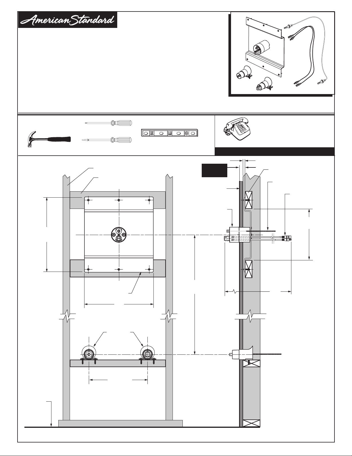
ROUGHING-IN DIMENSIONS
™
Hammer
Phillips Screwdriver
Flat Blade Screwdriver
2x4 WALL STUDS
(3), 2x4 SUPPORTS
Level
FINISHED WALL
R350
Certified to comply with ASME A112.18.1
U.S. Patent No. 5,819,789
LÍNEA DE AYUDA DIRECTA
Si desea obtener información o tiene preguntas, llame sin cargo al
(844) CRT-TEAM / (844) 278-8326
Los días de semana de 8:00 a.m. a 6:00 p.m. Hora normal del este.
EN MÉXICO: 01-800-839-1200
EN CANADÁ: 1-800-387-0369 (TORONTO 1-905-306-1093)
Los nombres de producto mencionados en este documento son marcas de comercio de AS America, Inc.
Para obtener más información sobre los productos American Standard Selectronic®, visite nuestro sitio web:
www.americanstandard-us.com o envíenos un correo electrónico a: [email protected]
1" MAX.
(25mm)
Los días de semana de 8:00 a.m. a 7:00 p.m. Hora normal del este.
1/4" REFFERENCE (6mm)
2x4 SUPPORT
CABLE CORD
M965614 (11/14)
EXTENSIONS
WIRES
© 2014
9-7/8"
(251mm)
MOUNTING PLATE
9"
(230mm)
PLASTER
GUARD
PLASTER
29-1/2" MAX.
(750mm) MAX.
GUARD
7" ± 1/4"
(178mm ± 6mm)
59"
(1500mm)
FINISHED
FLOOR
9" TO 12"
(229mm TO 305mm)
Page 2
INSTALL MOUNTING PLATE AND PLASTER GUARDS
1
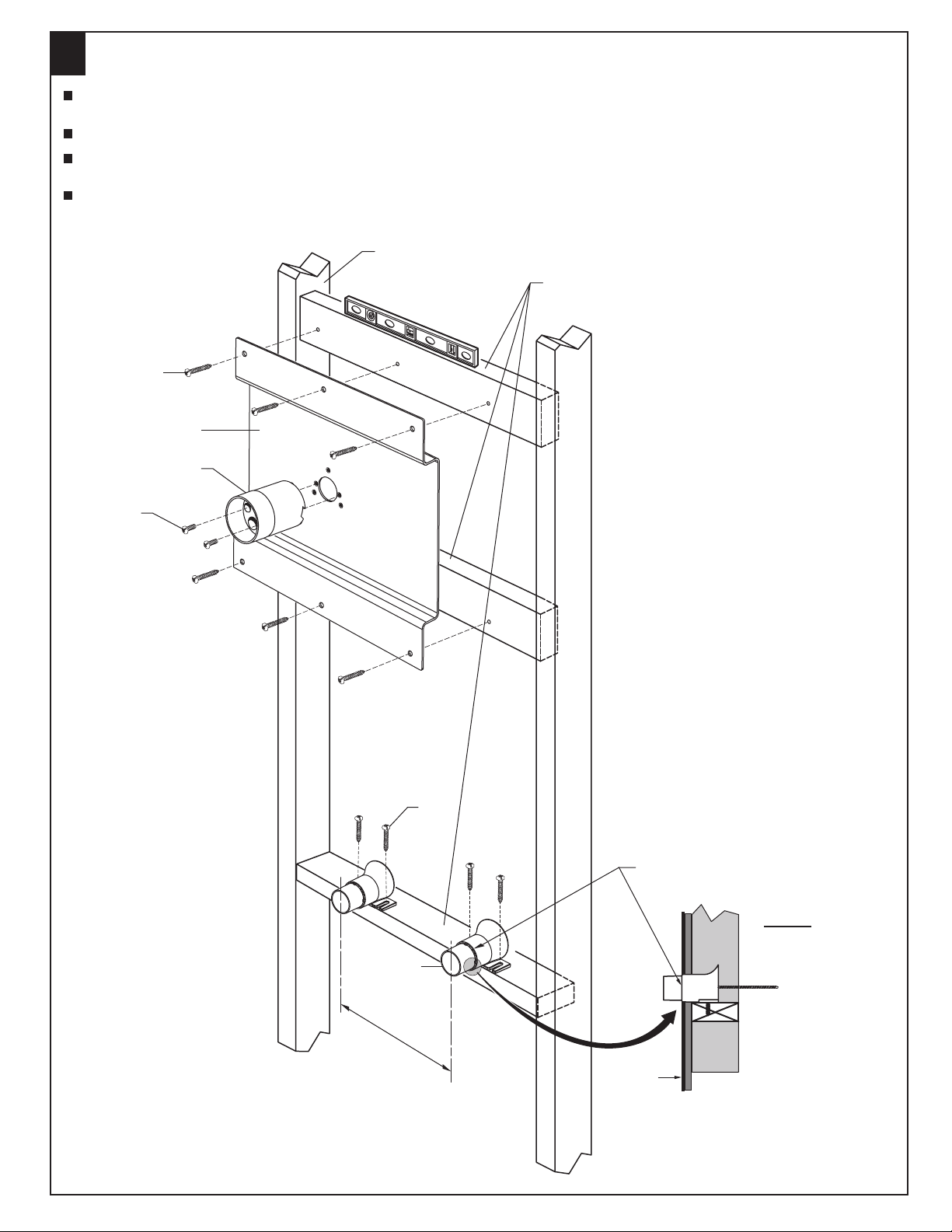
Level and install three 2x4 wooden supports between wall studs as shown. Two top pieces support the METAL MOUNTING PLATE (1).
Bottom piece supports the two cone shaped PLASTER GUARDS (2).
Center the MOUNTING PLATE (1) and attach to supports with six MOUNTING SCREWS (3) supplied.
Install the two bottom plaster guards onto the horizontal support. Secure with two MOUNTING SCREWS (3) on each unit. Make sure the
finished wall line on the plaster guard aligns with the front of the finished wall. Fig. A
Secure the TOP PLASTER GUARD (4) to the MOUNTING PLATE (1) with the two short SCREWS (5) supplied.
2x4 WALL STUDS
(3), 2x4
SUPPORTS
3
1
4
5
3
FINISHED WALL LINE
ON PLASTER GUARD.
Fig. A
2
9" TO 12"
(229mm TO 305mm)
FINISHED
WALL
M965614 (11/14)
Page 3
INSTALL EXTENSION CABLES AND PULL CORD
2
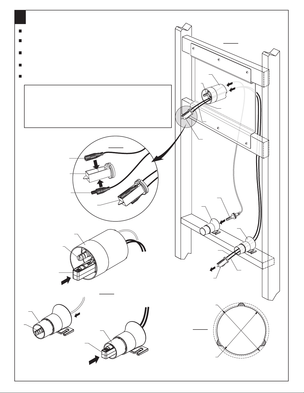
Insert each end of the EXTENSION CABLES (6, & 6a) through the back of
each PLASTER GUARD (2 & 4). Fig. A.
Insert each end of the EXTENSION CABLES (6, 6a) into the CABLE
HOLDERS (7) as shown. Fig. B.
Insert each CABLE HOLDER (7) into each PLASTER GUARD (2 & 4) until
they snap into place. Fig. C.
Insert each PULL CORD HOLDER (8) through the back of each PLASTER
GUARD (4 & 2a) until they snap into place. Fig. C.
Construct finished wall with a hole around the top PLASTER GUARD (4)
as well as each of the two bottom PLASTER GUARDS (2 & 2a).
*IMPORTANT: IT IS VERY IMPORTANT THAT THE FINISHED WALL
AROUND THE TOP PLASTER GUARD (4) IS AS CLOSE TO THE PLASTER
GUARD DIAMETER AS POSSIBLE. THE MAXIMUM DIAMETER OF THE
HOLE IS 55mm (2-3/16"). IF THE DIAMETER IS LESS THAN 50.2mm
(1-15/16") NOTCH FINISHED WALL TO ALLOW SCREW HOLE CLEARANCE.
!
SEE Fig. D.
IF HOLE AROUND THE TOP PLASTER GUARD (4) IS LARGER THAN
DIAMETER 55mm, FAUCET MOUNTING FLANGE WILL NOT MAKE A
WATER TIGHT SEAL WITH FINISHED WALL.
Fig. B
6
Fig. A
4
8
6a
6
7
2a
8
7
PLACE
SNAP INTO
8
7
6a
7
4
SNAP CORD
HOLDER INTO
PLACE FROM BEHIND
2
EXTENSION WIRES
IN HOLDER
Fig. C
2a
7
*MAX. DIA.55mm
(2-3/16")
Fig. D
8
2
6
6a
7
PLACE
SNAP INTO
MIN. 50.2mm (1-15/16")
SHADED AREA SHOWS THAT
ADDITIONAL NOTCHING MAY BE
REQUIRED FOR SCREW CLEARANCE
M965614 (11/14)
 Loading...