


SELECTRONIC®
Hard-Wired AC Powered Moments Lavatory Proximity Faucet
PRODUCT NUMBERS
2506.192, 2506.195
Product No.'s & Options |
1 |
Specifications |
2 |
How to Install |
2-3 |
Electrical Hook-up |
4-5 |
Maintenance |
6-7 |
FAQ,s |
8 |
Replacement Parts |
9 |
|
|
|
|
|
|
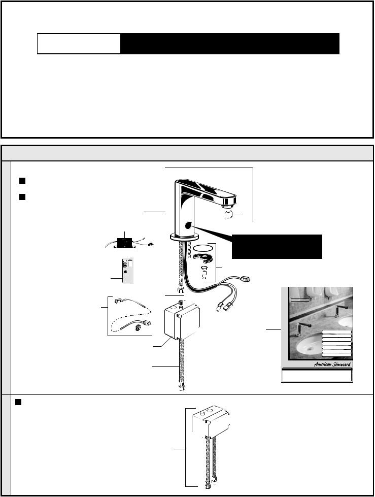
1. Remove the fitting and loose items from the carton.The illustration below shows the fitting and all loose items after they have been removed from the carton. Some items may be packaged partially assembled to other items.
10.
MODEL NUMBER:
2506.192 with cast spout, 1.5 GPM vandal resistant aerator.
2506.195 with cast spout, 0.5 GPM vandal resistant aerator
5
DO NOT REMOVE PROTECTIVE
FILM FROM SENSOR EYE UNTIL INSTALLATION IS COMPLETE.
6
SELECTRONIC®
Hard-Wired AC Powered Moments
Lavatory Proximity Faucet
PRODUCT NUMBERS
2506.192, 2506.195
7
10
Product No.'s & Options |
1 |
Specifications |
2 |
How to Install |
2-3 |
Electrical Hook-up |
4-5 |
Maintenance |
6-7 |
FAQ,s |
8 |
Replacement Parts |
9 |
OPTIONAL Mixing Valve
 605XTMV Thermostatic mixing valve, flex hoses 3/8" compression 20" hose length.
1 |
M 9 6 5 2 74 |
|
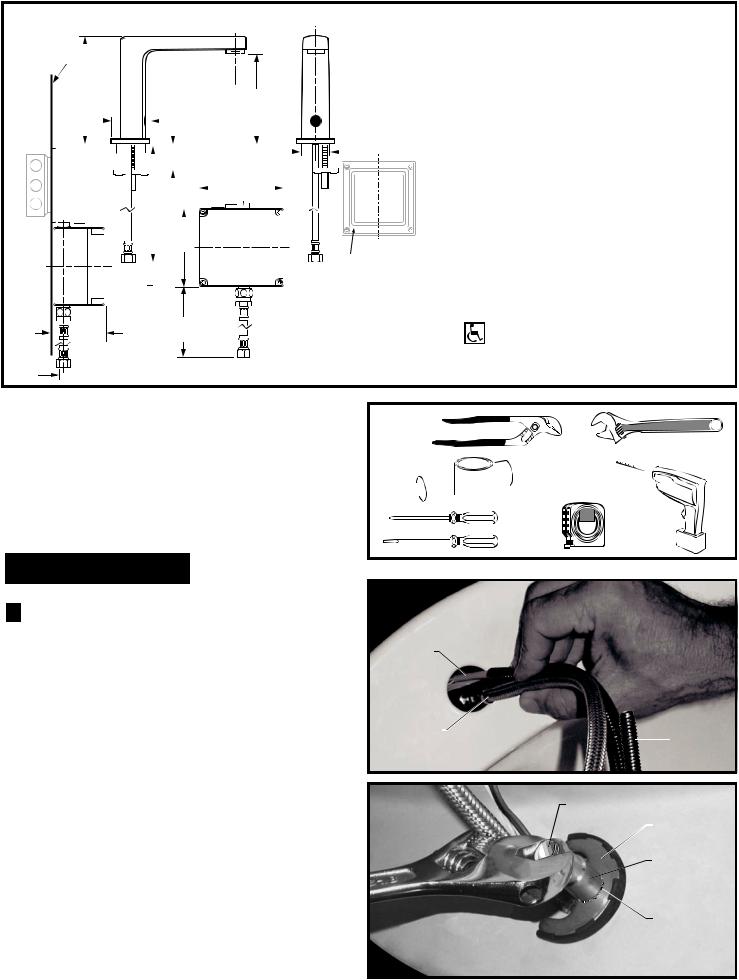
Fig. 1
FINISHED WALL
 154mm
154mm  (6-1/16)
159mm |
|
|
|
126mm |
|
|
|
|
|
|
|||||||||||||||
(5) |
|
|
|
|
|
|
|
||||||||||||||||||
(6-1/4) |
|
|
|
|
|
|
|
|
|
|
|
|
|
|
|
|
|
||||||||
|
|
|
|
|
|
|
|
|
|
|
|
|
|
|
|
|
|
|
|
|
|
|
|||
|
|
|
|
|
|
|
|
|
|
|
|
|
|
|
|
|
|
|
|
|
|
|
|
|
|
|
|
|
|
|
|
|
|
|
|
|
|
|
|
|
|
|
|
|
|
|
|
|
|||
|
|
|
|
|
|
|
|
|
|
|
|
|
|
|
|
|
|
|
|||||||
|
|
|
|
|
|
|
49mm |
|
|
32mm (1-1/4) |
|
|
|
|
|
|
|
||||||||
|
|
|
|
|
|
|
|
|
|
|
|
|
|
|
|
||||||||||
|
|
|
|
|
|
|
|
|
|
|
|
|
|
|
|
||||||||||
|
|
|
|
|
|
|
|
|
|
|
|
|
|
|
|
||||||||||
(2) |
|
|
|
|
|
125mm |
|
|
|
|
|
|
|
|
|||||||||||
|
|
|
|
|
|
|
|
|
|
|
|
|
|||||||||||||
|
|
|
|
|
|
|
|
|
|
|
|
|
|||||||||||||
|
|
|
|
|
|
|
|
|
|
|
|
|
|||||||||||||
|
|
|
|
|
|
|
|
|
|
|
|
|
|
|
|
|
|
|
|
|
|
|
|
||
|
|
|
|
|
|
|
|
|
|
|
|
|
|
|
|
|
|
|
|
|
|
|
|
||
|
|
|
|
|
|
|
|
|
|
|
|
|
|
|
|
|
|
|
|
|
|
|
|
||
|
|
|
|
|
|
|
|
|
|
|
|
|
|
|
|
|
|
|
|||||||
|
|
|
|
|
|
|
|
|
|
|
|
|
|
|
|
|
|
|
|
|
|
|
|
||
|
|
|
|
|
|
|
|
|
|
|
|
|
|
|
|
|
|
|
|
|
|
|
|
||
|
|
|
|
|
|
|
|
|
|
|
|
|
|
(4-7/8) |
|
|
|
|
|
|
|
|
|
||
|
|
|
|
|
|
|
|
|
|
|
|
|
|
|
|
|
|
|
|
|
|
|
|
|
|
|
|
|
|
|
|
|
|
|
|
|
|
|
|
|
|
|
|
|
|
|
|
|
|||
|
|
|
|
|
|
|
|
|
|
|
|
|
|
|
|
|
|
|
|
|
|
|
|
||
|
|
|
|
|
|
|
114mm |
|
|
|
|
|
|
|
|
|
|
|
|
|
|||||
(4-1/2) |
|
|
|
|
|
|
|
|
|
|
|
|
|
||||||||||||
|
|
|
|
|
|
|
|
|
|
|
|
|
|
|
|
|
|
|
|
|
|
|
|
|
|
381mm
(15)
 500mm 81mm (20)
  (3-3/16)
 3/8" COMP.
TOOLS REQUIRED; Fig. 2
1Channel Locks
2Adjustable Wrench
3Plumbers' Putty or Caulking
4Phillips Screwdriver
5Flat Blade Screwdriver
6Electric Drill & 1/4" Drill Bit
7Tape Measure
INSTALLATION
1 INSTALL SPOUT ASSEMBLY;
Fig. 1
|
Turn off hot and cold water |
|
CAUTION |
||
supplies before beginning |
1. Insert WIRES (1), FLEX HOSE (2) and SPOUT SHANK (3) through center hole of mounting surface.
Fig. 1a.
2.Assemble "C" WASHER (4), STAR WASHER (5) and LOCKNUT (6) onto threads of SPOUT SHANK (7) from underside of mounting surface. Fig. 1b.
3.Align FAUCET and tighten LOCKNUT (6). Fig. 1b.
ELECTRICAL BOX OR EQUIVALENT BY OTHERS
Roughing-in Dimensions
GENERAL DESCRIPTION:
Electronic faucet with proximity operation. Vandal resistant solid brass construction single post mounting. Operates on AC permanent power. Water pressure range from 20 to 125 psi. In-line strainer for solenoid is integral. Single inlet 3/8 compression, built-in checks, and flexible stainless steel 15" reach inlet hose for spout connection.
Note: All plumbing and electrical wiring must be installed in accordance with applicable codes, regulations and standards.
CODES AND STANDARDS:
These products meet or exceed the following coded standards:
ANSI A117.1 ASME A112.18.1 CSA B 125 NSF 61/Section 9
ADA Compliant
Fig. 2
1 2
3 


 7 6
7 6
4
10'
5
|
1 |
|
|
|
|
2 |
|
|
3 |
Fig. 1b |
|
7 |
|
|
|
|
|
||
|
|
|
|
|
|
|
4 |
|
|
|
|
6 |
|
|
|
|
5 |
|
|
2 |
M 9 6 5 2 74 |
 Loading...