


CE7 Pro, SE7 Pro,
CE7 Pro+ & SE7 Pro+
Edgers
Operator's Manual
Manual del operador
Manuel de l’utilisateur
ACTIVE MODELS: 07170A, 07176A
OBSOLETE MODELS: 07180A, 07175A
READ THIS BOOK |
EN |
English (2 - 12) |
LEA ESTE MANUAL |
ES |
Español (14 - 24) |
LISEZ CE MANUEL |
FR |
Français (26 - 36) |
This book has important information for the use and safe operation of this machine. Failure to read this book prior to operating or attempting any service or maintenance procedure to your Clarke American Sanders machine could result in injury to you or to other personnel; damage to the machine or to other property could occur as well. You must have training in the operation of this machine before using it. If your operator(s) cannot read this manual, have it explained fully before attempting to operate this machine.
All directions given in this book are as seen from the operator’s position at the rear of the machine.
Part No. LT068600 3/14

ENGLISH |
EN |
|
CONTENTS OF THIS BOOK |
|
|
Operator Safety Instructions............................................................... |
3 |
|
Introduction and Machine Specifications............................................. |
6 |
|
Machine Set-Up.................................................................................. |
|
7 |
How to Operate the Machine............................................................ |
11 |
|
Maintenance...................................................................................... |
|
12 |
SECTION II: Parts Manual |
|
|
Assembly Drawing ........................................................................... |
|
38 |
Parts List...................................................................................... |
|
39 |
Handle Assembly Drawing ............................................................... |
40 |
|
Parts List...................................................................................... |
|
41 |
Motor Housing Assembly Drawing and Parts List............................. |
42 |
|
Wiring Diagram................................................................................. |
|
43 |
 WARNING!
The Products sold with this Manual contain or may contain chemicals that are known to certain governments (such as the State of
California, as identified in its Proposition 65 Regulatory Warning Law) to cause cancer, birth defects or other reproductive harm. In certain locations (including the State of California) purchasers of these Products that place them in service at an employment job site or a publicly accessible space are required by regulation to make certain notices, warnings or disclosures regarding the chemicals that are or may be contained in the Products at or about such work sites. It is the purchaser’s responsibility to know the content of, and to comply with, any laws and regulations relating to the use of these Products in such environments. The Manufacturer disclaims any responsibility to advise purchasers of any specific requirements that may be applicable to the use of the Products in such
environments.
-2- |
Clarke® American Sanders Operator's Manual (EN) - CE7 Pro, SE7 Pro, CE7 Pro+, SE7 Pro+ |

ENGLISH EN
OPERATOR SAFETY INSTRUCTIONS
When you see this symbol, it means: Refer to instruction manual/booklet
When you see this symbol, it means: Wear eye protection.
General Power Tool Safety Warnings
WARNING!
Read all safety warnings and instructions. Failure to follow warnings and instructions may result in electric shock, fire and or serious injury.
Save all warnings and instructions for future use.
The term “power tool” in the warnings refers to your main-operated (corded) power tool or battery operated (cordless) power tool.
Work area safety
1.Keep work area clean and well lit. Clutter or dark areas invite accidents.
2.Do not operate power tools in explosive atmospheres, such as in the presence of flammable liquids, gasses, or dust.
Power tools create sparks which may ignite the dust or fumes.
3.Keep children and bystanders away while operating a power tool. Distractions can cause you to lose control.
Electrical safety
1.Power tool plugs must match the outlet. Never modify the plug in any way. Do not use any adapter plugs with earthed
(grounded) power tools. Unmodified plugs and matching outlets will reduce risk of electric shock.
2.Avoid body contact with earthed or grounded surfaces such as pipes, radiators, ranges, and refrigerators. There is an increased risk of electric shock if your body is earthed or grounded.
3.Do not expose power tools to rain or wet conditions. Water entering a power tool will increase the risk of electric shock.
4.Do not abuse the cord. Never use the cord for carrying, pulling or unplugging the power tool. Keep cord away from heat, oil, sharp edges or moving parts. Damaged or entangled cords increase the risk of electric shock.
5.When operating a power tool outdoors, use an extension cord suitable for outdoor use. Use of cord suitable for outdoor use reduces the risk of electric shock.
6.If operating a power tool in a damp location is unavoidable, use a ground fault circuit protected supply. Use of a ground fault circuit protector reduces the risk of electric shock.
Personal safety
1.Stay alert, watch what you are doing and use common sense when operating a power tool. Do not use a power tool while you are tired or under the influence of drugs, alcohol, or medication. A moment of in attention while operating power tools may result in serious personal injury.
2.Use personal protective equipment. Always wear eye protection. Protective equipment such as dust mask, non-skid safety shoes, hard hat, or hearing protection used for appropriate conditions will reduce personal injury.
3.Prevent unintentional starting. Ensure switch is in off-position before connecting to power source, picking up, or carrying the tool.
Carrying power tools with your finger on the switch or energizing power tools that have the switch on invites accidents.
4.Removing any adjustment wrench or key before turning the power tool on. A wrench or key left attached to a rotating part of the power tool may result in personal injury.
5.Do not overreach. Keep proper footing and balance at all times. This enables better control of the power tool in unexpected situations.
6.Dress properly. Do not wear loose clothing or jewelry. Keep your hair, clothing and gloves away from moving parts. Loose clothes, jewelry, or long hair can be caught in moving parts.
7.If devices are provided for the connection of dust extraction and collection facilities, ensure these are connected and properly used. Use of dust collection can reduce dust related hazards.
Clarke® American Sanders Operator's Manual (EN) - CE7 Pro, SE7 Pro, CE7 Pro+, SE7 Pro+ |
- 3 - |

ENGLISH EN
POWER TOOL USE AND CARE
1.Do not force the power tool. Use the correct power tool for your application. The correct power tool will do the job better and safer at the rate it was designed.
2.Do not use the power tool if the switch does not turn it on and off. Any power tool that cannot be controlled with the switch is dangerous and must be repaired.
3.Disconnect the plug from the power source and from the power tool before making any adjustments, changing accessories or storing the power tool. Such preventative safety measures reduce the risk of starting the power tool accidently.
4.Store idle power tools out of the reach of children and do not allow persons unfamiliar with the power tool or these instructions to operate the power tool. Power tools are dangerous in the hands of untrained users.
5.Maintain power tools. Check for misalignment or binding of moving parts, breakage of parts and any other condition that may affect the power tool’s operation. If damaged, have the power tool repaired before use. Many accidents are caused by poorly maintained power tools.
6.Use the power tool, accessories and tool bits etc. in accordance with these instructions, taking into account the working conditions and the work to be performed. Use of the power tool for operations different from those intended could result in a hazardous situation.
SERVICE
Have the power tool serviced by a qualified repair person using only identical replacement parts. This will ensure that the safety of the power tool is maintained.
SAFETY WARNINGS FOR SANDING OPERATIONS
1.This power tool is intended to function as a sander. Read all safety warnings, instructions and specifications provided with this power tool. Failure to follow all instructions listed below may result in electric shock, fire, or personal injury.
2.Operations such as grinding, wire brushing, polishing or cutting-off, are not recommended to be performed with this power tool. Operations for which the tool was not designed may create a hazard and cause personal injury.
3.Do not use accessories which are not specifically designed and recommended by the tool manufacturer. Just because the accessory can be attached to your power tool, it does not assure safe operation.
4.The rated speed of the accessory must be at least equal to the maximum speed marked on the power tool. Accessories running faster than their rated speed can break and fly apart.
5.The outside diameter and thickness of your accessory must be within the capacity rating of your power tool. Incorrectly sized accessories cannot be adequately guard or controlled.
6.The arbor size of wheels, flanges, backing pads or any other accessory must fit the spindle of the power tool.
Accessories with arbor holes that do not match the mounting hardware of the power tool will run out of balance, vibrate excessively and may cause loss of control.
7.Do not use damaged accessory. Before each use inspect the accessory such as abrasive wheel for chips or cracks, backing pad for cracks, tear or excess wear, wire brush for loose or cracked wires. If power tool or accessory is dropped, inspect for damage or install an undamaged accessory. After inspecting or installing an accessory, position yourself or bystanders away from the plane of the rotating accessory and run the power tool at maximum no-load speed for one minute. Damaged accessories will normally break apart during this time.
8.Wear personal protective equipment. Depending on application, use face shield, safety goggles or safety glasses. As appropriate, wear dust mask, hearing protectors, gloves and workshop apron capable of stopping flying debris generated by various operations. The eye protection must be capable of stopping flying debris generated by various operations. The dust mask or respirator must be capable of filtering particles generated by your operations. Prolonged exposure to high intensity noise may cause hearing loss.
9.Keep bystanders a safe distance away from work area. Anyone entering the work area must wear personal protective equipment. Fragments of work piece or a broken accessory may fly away and cause injury beyond immediate area of operation.
10.Hold power tool by gripping insulated surfaces (handle) only, when performing an operation where the cutting accessory may contact hidden wiring or its own cord. Cutting accessory contacting a “live” wire may make exposed metal parts of the power tool “live” and shock the operator.
11.Position the cord clear of the spinning accessory. If you lose control, the cord may be cut or snagged and your arm or hand may be pulled into the spinning accessory.
12.Never lay the power tool down until the accessory has come to a complete stop. The spinning accessory may grab the surface and pull the power tool out of your control.
13.Do not run the power tool while carrying it at your side. Accidental contact with the spinning accessory could snag your clothing, pulling the accessory into your body.
-4- |
Clarke® American Sanders Operator's Manual (EN) - CE7 Pro, SE7 Pro, CE7 Pro+, SE7 Pro+ |

ENGLISH EN
14.Regularly clean the power tools air vents. The motor’s fan will draw the dust inside the housing and excessive accumulation may cause electrical hazards.
15.Do not operate the power tool near flammable materials. Sparks could ignite these materials.
16.Do not use excessively oversized sanding disc paper. Follow manufacturer’s recommendations when selecting sanding paper. Larger sanding paper extending beyond the sanding pad presents a laceration hazard and may cause snagging, tearing of the disc or kickback.
KICKBACK AND RELATED WARNINGS
Kickback is a sudden reaction to a pinched or snagged rotating wheel, backing pad, brush or any other accessory. Pinching or snagging causes rapid stalling of the rotating backing pad which in turn causes uncontrolled power tool to be forced in the opposite direction of the backing pad’s rotation at the point of the binding.
For example, if an abrasive wheel is snagged or pinched by the work piece, the edge of the wheel that is entering into the pinch point can dig into the surface of the material causing the wheel to climb out or kick out. The wheel may either jump toward or away from the operator, depending on direction of the wheel’s movement at the point of pinching. Abrasive wheels may also break under these conditions.
Kickback is the result of power tool misuse and incorrect operating procedures or conditions and can be avoided by taking proper precautions as given below.
1.Maintain a firm grip on the power tool and position your body and arms to allow you to resist kickback forces. Always use auxiliary handles, if provided for maximum control over kickback or torque reactions during start up. The operator can control torque reactions or kickback forces, if proper precautions are taken.
2.Never place your hand near the rotating accessory. Accessory may kickback over your hand.
3.Do not position your body in the area where power tool will move if kickback occurs. Kickback will propel the tool in the direction opposite to the wheel’s movement at the point of the snagging.
4.Use special care when working corners, sharp edges etc. Avoid bouncing and snagging the accessory. Corners, sharp edges or bouncing have a tendency to snag the rotating accessory and cause loss of control or kickback.
ADDITIONAL RULES FOR SAFE OPERATION
1.Empty the dust bag or dust collection receiver frequently. Do not leave residue in dust bag or dust collection receiver unattended. Always empty in a non-combustible metal container. Sanding wood or varnish produces dust that can selfignite and cause injury or damage. Follow this precaution for storage.
2.Set all exposed nails. Sweep loose abrasive away from work area. Do not strike metal pipes, ect., with sanding paper.
Striking metal or abrasive particles with sanding paper produces sparks that could ignite the sanding dust which can cause injury or damage.
3.Do not operate a partially assemble power tool. Keep all adjustments within manufacturer’s specifications. Keep all fasteners tight. Operating a partially assembled power tool could result in injury to the operator or bystander and could cause damage to the equipment or surroundings.
4.Do not attempt to change the sanding paper while the power tool is running. The sanding pad can snag clothing and cause injury to limbs and moving sanding paper can cause abrasions.
5.The power tool should only be used on an electrical system (mains) that is rated for the electrical requirements of the power tool as shown on the nameplate. Use only on an earthing (grounded) system. Do not service the power tool if it is energized or connected to an electrical circuit. Improper use could cause fire or electric shock.
Clarke® American Sanders Operator's Manual (EN) - CE7 Pro, SE7 Pro, CE7 Pro+, SE7 Pro+ |
- 5 - |

ENGLISH EN
INTRODUCTION AND MACHINE SPECIFICATIONS
The models CE and SE 7 were designed for floor sanding where larger machines are impractical or cannot reach. They are suitable for rough and finish sanding on strip or parquet flooring. They can be used on a wide variety of wood species including pine, oak, or maple. The added reach enables them to be used under obstructions or toe-kick. Either model will accept 7” x 7/8” mounting hole or 7” hook and loop abrasive.
|
Part No. |
07170A |
07176A |
07180A |
07175A |
||||||
|
|
|
|
|
|
|
|||||
|
Model |
|
CE 7 PRO+ |
SE 7 PRO + |
SE7 PRO |
CE7 PRO |
|||||
|
|
|
|
|
|
|
|
|
|
|
|
|
|
|
|
V |
120 |
120 |
120 |
120 |
|
|
|
|
|
Electrical |
A |
12 |
12 |
12 |
12 |
|
|
|
|
|
|
|
|
|
|
|
|
|
|
||
|
|
Hz |
60 |
60 |
60 |
60 |
|
|
|
||
|
|
|
|
W |
1.3 kW |
1.3 kW |
1.3 kW |
1.3 kW |
|||
|
|
|
|
|
|
|
|
|
|
|
|
|
|
|
|
Cable |
25' 14-3 |
25' 14-3 |
NA |
NA |
|||
|
|
|
|
|
Grey Rubber |
Grey Rubber |
|
|
|
|
|
|
|
Environmental |
Vibration Exposure |
4.9 m/s2 |
4.9 m/s2 |
4.0 m/s2 |
4.0 m/s2 |
||||
|
|
|
|
||||||||
|
|
|
|
|
|
|
|
|
|
|
|
|
|
|
|
Sound Emissions |
91 dB(A) |
91 dB(A) |
91 dB(A) |
91 dB(A) |
|||
|
|
|
|
|
|
|
|
|
|
|
|
|
|
|
|
Pad Speed |
3640/3030 rpm |
3640/3030 rpm |
3640 rpm |
3640 rpm |
|||
|
|
|
|
|
|
|
|
|
|
||
|
|
|
|
Abrasive (in/mm) |
7/178 Hook & loop |
7/178 Hook & loop |
7/178 Hook & loop |
7/178 Hook & loop |
|||
|
|
Performance |
|
or 7/8" Mounting hole |
or 7/8" Mounting hole |
or 7/8" Mounting hole |
or 7/8" Mounting hole |
||||
|
|
|
|
|
|
|
|
|
|
||
|
|
Air Flow (CFM) |
136 |
136 |
136 |
136 |
|
|
|
||
|
|
|
|
|
|
|
|||||
|
|
|
|
|
|
|
|
|
|
|
|
|
|
|
|
Effective Reach |
5.24/13.31 |
3.76/9.55 |
3.76/9.55 |
5.24/13.31 |
|
|
|
|
|
|
|
@ 3.5" Height (in/cm) |
|
|
|
|
|
|
|
|
|
|
|
|
|
|
|
|
|||
|
|
|
|
Dimensions (in/cm) |
16.61x11.78x12.69 / |
15.02x11.78x12.68 / |
15.02x11.78x12.68 / |
16.6x11.78x12.69 / |
|||
|
|
|
|
|
42.2x29.932.2 |
38.2x29.9x32.2 |
38.2x29.9x32.2 |
42.2x29.9x32.2 |
|||
|
|
|
|
Weight (lbs./kg) |
36.5 / 16.6 |
35.5 / 16.1 |
33.0 / 15.0 |
34.0 /15.5 |
|
|
|
|
|
|
|
|
|
|
|
|
|
|
|
|
|
|
|
Weight (lbs./kg) |
47.5 / 21.6 |
46.5 / 21.1 |
39.5 / 18.0 |
40.5 / 18.4 |
|
|
|
|
|
Shipping |
|
|
|
|
|
|
|
|
|
|
|
Dimensions (in/cm) |
20x17.25x22.75 / |
20x17.25x22.75 / |
20x17.25x22.75 . |
20x17.25x22.75 / |
|||||
|
|
|
|
||||||||
|
|
|
|
|
51x43.8x57.8 |
51x43.8x57.8 |
51x43.8x57.8 |
51x43.8x57.8 |
|||
|
|
|
|
|
|
|
|
|
|
||
|
|
|
|
|
|
|
|
|
|
|
|
-6- |
|
Clarke® American Sanders Operator's Manual (EN) - CE7 Pro, SE7 Pro, CE7 Pro+, SE7 Pro+ |
|||||||||
|
ENGLISH |
EN |
MACHINE SET-UP |
|
|
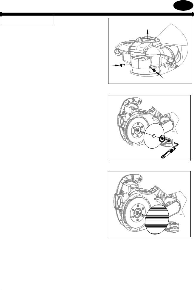
Fig. 1.1 OPERATING HANDLE |
|
|
The operating handle provides control and comfort to the sanding |
|
|
experience (all models). On models 07170A and 07176A, the handles |
|
|
may be set to a greater height depending on preference. Remove the |
|
|
4 screws securing the handle to the machine. Raise the handle until |
|
|
the holes align then reinstall the 4 screws. |
|
|
Fig. 2.1, 2.2 Abrasive Driver |
|
|
The unit will accept either 7” hook and loop or 7”x7/8” center |
|
|
hole abrasive disc. Motion is delivered to the abrasive through a |
Figure 1.1 |
|
replaceable spring steel sanding disc (11226A) having a medium hook |
|
|
surface (39864A). The unique geometry provides a flat finish and |
|
|
smooth sanding experience, reducing objectionable scratches. The |
7" x 7/8" Mounting Hole |
|
unit is equipped with a retaining screw, washer, and onboard wrench |
|
|
for use with 7” x 7/8” abrasive. When installing abrasive disc, take |
|
|
care to center disc on driver. |
|
|
NOTE: When using 7” x 7/8” abrasive, hold the sanding disc while tightening the retaining screw. Do not over tighten or removal will be difficult.
To avoid injuring the hook surface on the driver when sanding thick paint, varnish or wax, it is recommended you stack two discs on the driver using a course open coat abrasive.
Figure 2.1
7" Hook and Loop |
Figure 2.2
Clarke® American Sanders Operator's Manual (EN) - CE7 Pro, SE7 Pro, CE7 Pro+, SE7 Pro+ |
- 7 - |
ENGLISH EN
MACHINE SET-UP
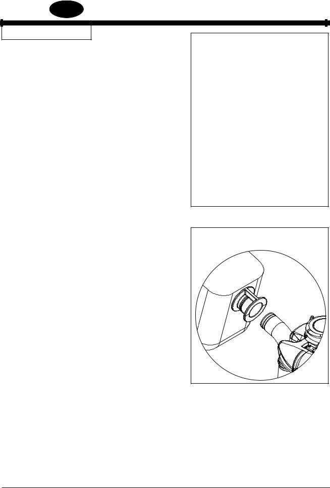
Fig. 3.1, 3.2 Dust Management
This sanding machine is designed to be operated with a remote vacuum dust collection system or with the included dust bag.
Preparing Remote Vacuum Dust Collection Systems
To prepare the machine for remote vacuum dust collection systems that have a 2” hose end, follow this procedure:
1.Install 2” hose end (figure 3.1, A) directly over the exhaust tube (figure 3.1, B).
2.The exhaust tube can be rotated for optimum convenience.
To prepare the machine for remote vacuum dust collection systems that have a 1-1/2” hose end, follow this procedure:
1.Install the optional 2” x 1-1/2” hose end adaptor (Part No. 30563A) (figure 3.1, C) over the exhaust tube (figure 3.1, B).
2.Insert 1-1/2” hose end (figure 3.1, D) into the adaptor (figure 3.1, C).
NOTE: Start the remote vacuum collection system before operation.
Preparing to use the included dust bag
To prepare the machine for use with the included dust bag (Part No.
53544C), follow this procedure:
1.Install the dust bag by pressing the end onto the exhaust tube until the ring locks into the groove (figure 3.2). This is best done by pressing on the back of the bag opening with the palm of your hand.
2.The exhaust tube can be rotated for optimum convenience.
3.To remove the dust bag from the exhaust tube, pry up the end of the bag opening to partially release the internal rib from the groove, then pull.
4.To empty the dust bag, unzip the disposal flap and force contents out by inverting the bag.
NOTE: For best results, empty frequently. Follow all warnings posted in this manual and on the dust bag.
A |
D |
1.5" Hose from |
2" Hose from |
|
vacuum system |
|
(not included) |
|
vacuum system |
|
|
|
|
|
(not included) |
|
|
B
Exhaust Tube
C
(30563A) 2" Tube x 1.5" hose adaptor
Figure 3.1
Install the dust bag by pressing the end onto the exhaust tube until the ring locks into the groove.
Figure 3.2
-8- |
Clarke® American Sanders Operator's Manual (EN) - CE7 Pro, SE7 Pro, CE7 Pro+, SE7 Pro+ |
ENGLISH EN
MACHINE SET-UP
Fig. 4.1 Electrical Connection
The unit is equipped with a grounding NEMA L5-15P locking plug (fig 4.1). Connection to an electrical source is made through an extension cord (optional 42300A). Connect the plug on the extension cord
to a wall outlet matching one of the two shown (fig. 4.2). Plug the appliance into the matching connector then twist clockwise until the cables are locked.
NOTE: The extension cord must be sized to a minimum of 14 AWG 2 conductor with ground not exceeding 50’ in length and have for ends a NEMA 5-15P plug and NEMA L5-15R connector. An extension cord sized smaller than 14 AWG or greater than 50’ in length will overheat and potentially cause a fire.
DANGER!
This appliance must be grounded. Should an electrical malfunction occur, the grounding conductor provides a path to harmful charge. Do not connect this appliance to any other wall outlet than one of those shown in fig. 4.2. Consult an electrician if there is reason to doubt that the wall outlet is not wired correctly. Do not remove pin on the extension cord. Do not use the appliance with a damaged cord or connectors.
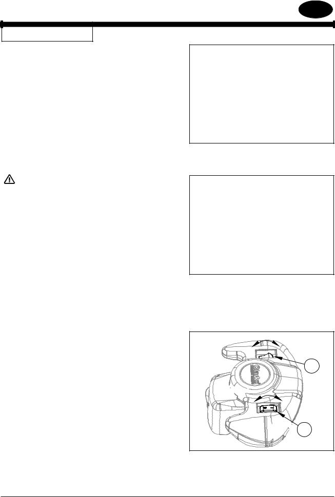
Fig. 5.1 Controls
All controls are conveniently located on the handle providing comfort and security. The master control switch (all models) is activated with a rocking motion as shown in figure 5.1a. The switch will remain activated until it is deliberately deactivated or if there is a loss of power. The speed control switch (models 07170A and 07176A only) varies the abrasive disc speed (fig. 5.1b). The switch is operated with a rocking motion. The switch will remain in a particular setting until it is deliberately changed.
Figure 4.1
Figure 4.2
LOW HIGH
B

 OFF
OFF
 ON
ON


 A
A
Figure 5.1
Clarke® American Sanders Operator's Manual (EN) - CE7 Pro, SE7 Pro, CE7 Pro+, SE7 Pro+ |
- 9 - |
ENGLISH EN
MACHINE SET-UP
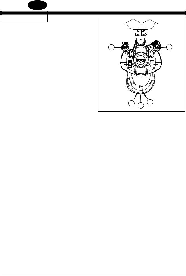
Fig. 6.1 Sanding Pattern
The unit is factory set to sanding pattern 2.
1. |
To alter the sanding pattern to 1: |
A |
|
B |
|
a.) |
Loosen the locknuts on A & B. |
|
|
|
|
b.) |
Turn stem A counter clockwise and stem B clockwise in 1/4 turn |
|
|
|
|
|
increments until the desired pattern is achieved. |
|
|
|
|
c.) |
Tighten locknuts on A & B. |
|
|
|
|
2. |
To alter the sanding pattern to 3: |
|
|
|
|
|
a.) |
Loosen the locknuts on A & B. |
|
|
|
|
b.) |
Turn stem A clockwise and stem B counter clockwise until |
|
|
|
|
the desired pattern is achieved. |
1 |
2 |
3 |
|
|
|
|
|||
|
c.) |
Tighten locknuts on A & B. |
|
|
|
|
|
|
|
||
Figure 6.1
3.To move the pattern to the outer edge of the sanding disc:
a.) |
Loosen locknuts on A & B. |
b.) |
Turn stem A & B clockwise in 1/4 turn increments until the |
desired pattern is achieved. |
|
c.) |
Tighten locknuts on A & B. |
4.To move the pattern away from the edge on the sanding disc:
a.) |
Loosen locknuts A & B. |
b.) |
Turn stems A & B counter clockwise until the desired |
pattern is achieved. |
|
c.) |
Tighten locknuts on A & B. |
5.To restore the pattern to factory setting, see illustration in parts list 1 on page 34.
-10- |
Clarke® American Sanders Operator's Manual (EN) - CE7 Pro, SE7 Pro, CE7 Pro+, SE7 Pro+ |
ENGLISH EN
How to Operate the Machine
Operating Instructions
1.Install the abrasive disc.
2.Connect the dust management system.
3.Connect the extension cord to a wall outlet and then to the machine.
4.Raise the sanding disc from the surface then activate the master control switch.
5.Lower the sanding disc to the surface and begin sanding.
Do not press down on the handle while sanding. Doing so will promote objectionable scratches and an uneven finish.
Depending on technique and desired results, use one or a combination of the two methods shown in figures 7.1 and 7.2.
6.For optimum dust management performance when using the included dust bag (53544C), empty frequently. Do not overfill.
Empty when dust reaches full line.
WARNING!
Follow all instructions found in this manual and on the dust bag pertaining to the safe storage and handling of sanding dust.
Figure 7.1
Figure 7.2
Clarke® American Sanders Operator's Manual (EN) - CE7 Pro, SE7 Pro, CE7 Pro+, SE7 Pro+ |
- 11 - |
ENGLISH EN
MAINTENANCE
Drive Belt
Replace the drive belt every 1000 hours or on the 3rd set of carbon brushes. Replace lower motor bearing at every drive belt change interval. Replace upper motor bearing every 1500 hours.
Motor Bearings
Replace lower motor bearing at every drive belt change interval. Replace upper motor bearing every 1500 hours.
Abrasive Driver Bearings
The bearings should not need replacement for the life of the machine.
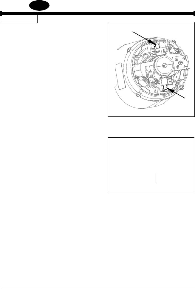
Carbon Brushes (Figures 8.1 and 8.2)
Replace the carbon brushes (see figure 8.1) every 350-400 hours depending on use. Replace both brushes if either has worn to the wear indicator (see figure 8.2). Have the commutator turned and undercut every 3rd replacement.
Figure 8.1
Wear Indicator
Figure 8.2
-12- |
Clarke® American Sanders Operator's Manual (EN) - CE7 Pro, SE7 Pro, CE7 Pro+, SE7 Pro+ |

ENGLISH EN
Clarke® American Sanders Operator's Manual (EN) - CE7 Pro, SE7 Pro, CE7 Pro+, SE7 Pro+ |
- 13 - |

ESPAÑOL ES
LEA ESTE MANUAL
Este manual contiene información importante acerca del uso y la seguridad de la máquina. Si no lee el manual antes de utilizar su máquina Clarke American Sanders o de intentar realizar los procedimientos de reparación o mantenimiento de la misma, usted o el resto del personal podrían sufrir lesiones; asimismo, podrían producirse dańos a la máquina o a otras propiedades. Antes de utilizar la máquina, es necesario recibir la capacitación adecuada en la operación de la misma. Si el operador de la máquina no sabe leer en espańol, explíquele el manual exhaustivamente antes de que intente utilizarla.
TODAS LAS INDICACIONES INCLUIDAS EN ESTE MANUAL SE OFRECEN DESDE LA POSICIÓN DEL OPERADOR EN LA PARTE POSTERIOR DE LA MÁQUINA.
CONTENIDO DE ESTE LIBRO |
|
Instrucciones de seguridad para el operador.................................... |
15 |
Introducción y especificaciones de la máquina................................. |
18 |
Instalación de la máquina................................................................. |
19 |
Operación de la máquina.................................................................. |
23 |
Mantenimiento .................................................................................. |
24 |
Sección II Repuestos y manual de servicio |
|
Plano de montaje #1......................................................................... |
38 |
Listado de piezas de montaje #1................................................. |
39 |
Plano de montaje #2......................................................................... |
40 |
Listado de piezas de montaje #2................................................. |
41 |
Plano de montaje / Listado de piezas de montaje #3....................... |
42 |
Plano de cableado............................................................................ |
43 |
ADVERTENCIA:
Los Productos a la venta en este Manual contienen, o pueden contener, productos químicos reconocidos por algunos gobiernos
(como el Estado de California, según lo indica en su Proposición 65, Ley de Advertencia Regulatoria) como causantes de cáncer, defectos de nacimiento u otros daños reproductivos. En algunas jurisdicciones (incluido el Estado de California), los compradores de estos Productos que los coloquen en servicio en un emplazamiento laboral o en un espacio de acceso público tienen la obligación regulatoria de realizar determinados avisos, advertencias o divulgaciones respecto de los productos químicos contenidos o posiblemente contenidos en los Productos utilizados en tal lugar. Es la responsabilidad del comprador conocer y cumplir con todas las leyes y reglamentaciones relacionadas con el uso de estos Productos en tales entornos. El Fabricante niega toda responsabilidad de informar a los compradores sobre requisitos específicos que pueden regir el uso de los Productos en tales entornos.
-14- |
Clarke® American Sanders Manual del operador (ES) - CE7 Pro, SE7 Pro, CE7 Pro+, SE7 Pro+ |
 Loading...