

American Metal Ware P300E, P-300, RAPS400E, P400E, P400ESHP Installation Manual
...
Shuttle Brewer & Airpot/Shuttle Brew ers
Operation and Instruction Man u al
For Models P300E, P400E, P400ESHP, RAP300E,
RAP400E, RAPS300E, RAPS400E
Installation:
See rough-in drawings in this manual for di men sions and lo ca tions of
electric and water input.
Set-Up/Position
1) Remove the brewer from the packing material and attach its legs.
2) Position the brewer on a strong, stable table or counter. Check
the level front to back and side to side. Adjust the legs to the correct level.
IMPORTANT:
THE PERSON INSTALLING THIS APPLIANCE IS RESPONSIBLE
FOR ENSURING THAT ELECTRIC AND WATER CONNECTIONS
MEET THE RE QUIRE MENTS OF THE NATIONAL ELECTRIC
CODE, NATIONAL PLUMBING CODE, AND ANY LOCAL
ORDINANCES.
The electric and water hook-up locations are behind the front pan el.
Re move the four screws fastening this panel for access to these
con nec tions.
Table of Contents
Installation and Start-up ....................................... 1-2
Warning Labels ...........................................................3
Operation .......................................................... 4
Adjustments ........................................................ 5-8
Care and Cleaning ............................................... 9-10
Service ............................................................... 10-11
Troubleshooting
Filling Problems ....................................... 12
Heating Problems ................................. 13
Brewing Problems ................................ 14
Parts Illustrations
Models P300E & P400E ....................... 15
Model P400ESHP .....................................16
Model RAP400E ..................................... 17
Model RAPS400E ................................... 18
VSB-400................................................ 19
Shuttle CS-LL .......................................... 20
Rough-In Drawings
Model P300........................................................... 21
Model P400 & P400ESHP ...................... 22
Model RAP300 ......................................... 23
Model RAP400 ........................................ 24
Model RAPS300 ....................................... 25
Model RAPS400 ..................................... 26
VSB-300 .................................................. 27
VSB-400 ................................................ 28
Wiring Diagrams
P300E/P400E with 1 Batch Timer ......... 29
P300E/P400E with 2 Batch Timer........ 30
RAP300E/RAP400E................................31
RAPS300E/RAPS400E........................32
P400ESHP ...........................................33
Drawing #091-548 .................................34
Drawing #091-182 .....................................35
Water Hook-up
1) The water line may enter through holes on the rear or the bottom of the brewer. Use the right hand opening for water.
2) Use 3/8" copper or flexible water line to prevent strain. Do not use low temperature plastic tubing. The connection
to the fill valve is 3/8" flare.
3) Water line pressure must be from 30 to 70 psi.
4) Hot (up to 160°F) or cold water may be used. Hot water offers faster recovery between brews.
5) Install a shut-off valve near the brewer.
6) Installing a filtering system can improve the taste of brewed coffee and extend the life of the brewer. If your water
has high calcium (lime), chlorine, or iron content, this is especially important. The filter should be the lime inhibiting
type if cold water is used. Contact your local water treatment professional regarding the type of filter you should use
based on water quality and volume of water used.
© Grindmaster Corporation, 1998
PRINTED IN U.S.A.
0307 FORM # AM-309-08
Part # 090-077
Prior authorization must be obtained from Grindmaster Corporation for all warranty claims.
Grindmaster Corporation
4003 Collins Lane
Louisville, KY 40245 USA
(502) 425-4776
(800) 695-4500 (USA & Canada only)
(800) 568-5715 (Technical Service Only)
FAX (502) 425-4664
www.grindmaster.com
WARNING
ELECTRIC SHOCK HAZARD!
Installation of this appliance should be performed by
qualified service per son nel only. Improper installation
could result in elec tro cu tion.

Page 2
Shuttle Brewers & Airpot/Shuttle Brewers
Installation (con't)
Electric Hook-up
1) The electric ratings for your brewer are printed on its nameplate. Typical electric ratings
are:
P300, P400, RAP300, RAP400
Optional 120/208V, 3.8kW, 18A or 120/240V 5.0kW, 21A, 1 phase
Standard 120/208V, 5.0kW, 24A or 120/240V 6.6kW, 28A, 1 phase
RAPS300, RAPS400
Standard 120/208V, 4.4KW, 21A or 120/240V, 5.6KW 24A, 1 phase
P400ESHP
Standard 440V, 12.5KW, 16.3A, 3 phase WYE
If the brewer includes the three heater tank option C21A, the ratings will be different. Always
see the nameplate for correct ratings.
2) The brewer should be connected to its own circuit with a fused disconnect switch or a
circuit breaker near the brewer.
3) Attach the appropriately sized cord to the brewer with a cord grip for the 1 1/2" electric input
opening. The cord may enter through the rear or bottom on the left side of the brewer. Use
an oil resistant cord such as type SO, SOO, SAO, STOO, SEO, SJO, SJOO, SJTO, SJTOO,
SJEO, HSO, HSOO, HSJO, or HSJOO. Alternatively, flexible conduit and type THHN wires
may be used. Use only copper conductors.
4) Standard connection is 1 phase 3 wire. Connect the two lines to L1 and L2 on the terminal
block. If the brewer is wired for three phase, a lug, L3, is provided on the terminal block. A
neutral line must be connected to the N terminal.
5) The body of the brewer must be grounded. A ground lug is provided for this purpose.
Start-up
1) Turn on the water supply to the brewer. Check for leaks.
2) Turn on the electric supply. The brewer will begin to fill.
3) Replace the front access panel.
4) Once the brewer is full, it will take 15 to 35 minutes to heat. The water hot light will turn on
when up to temperature.
5) Insert the brew baskets and place a shuttle or airpot under the baskets. Brew at least one
batch from each side. Check the level in the container to be sure the brew volume is correct.
Remember that when using coffee, the level will be lower. Do this for both batch sizes when
provided. The water must be hot to check the levels. If adjustments are needed, see the
adjustments section of this manual.
WARNING
Never use the ground conductor as a neutral. This could cause electrocution.
Page 3
Shuttle Brewers & Airpot/Shuttle Brewers
Warning Labels
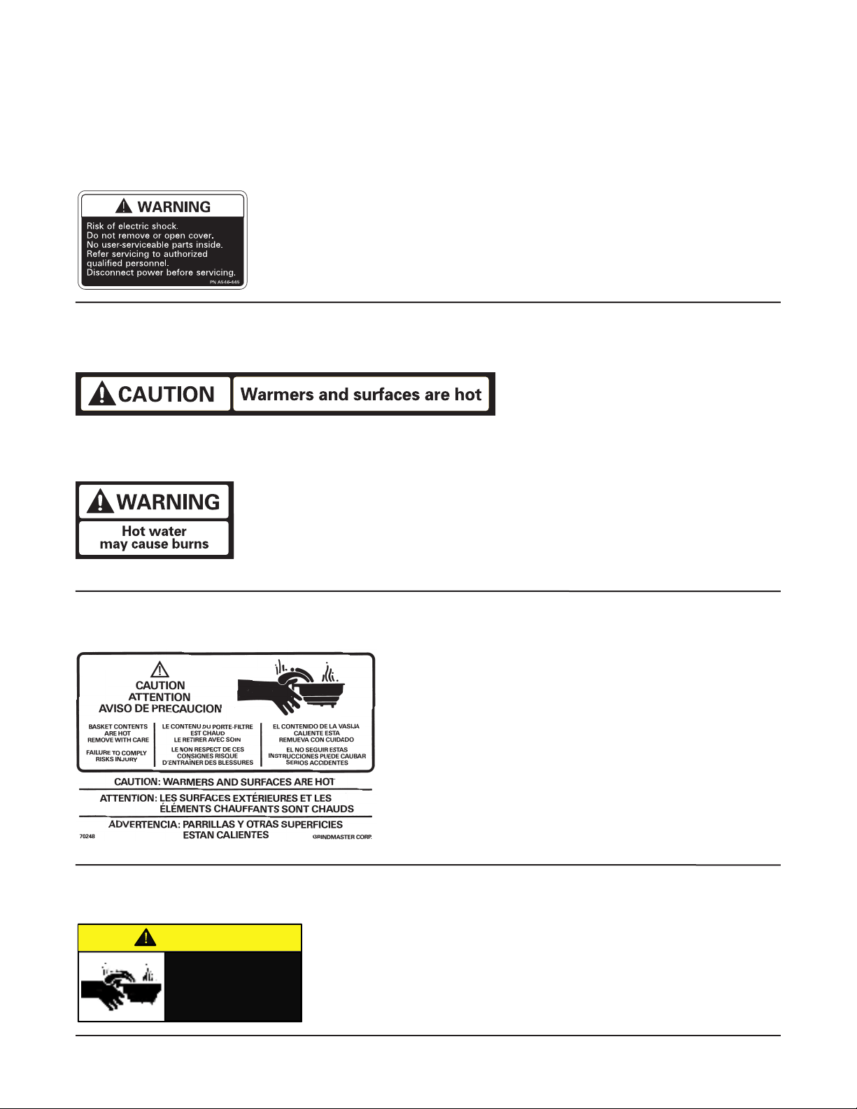
The following warning labels were on your dispenser when it was shipped from the factory. They should remain on your dispenser
in good, readable condition at all times. If one of your labels is missing or damaged, order a replacement label immediately.
Part # A546-445
Located on front splash panel and lid of machine.
Part # A546-213
Located on front splash panel.
Part # A71949
Located on brew baskets.
Part # A546-020 (P-300), A546-129 (P-400)
Located near warmer plates.
Part # A546-020 (P-300), A546-129 (P-400)
Located near water faucet.
CAUTION
Hot liquid in brew
basket could cause
burns.
Remove with care.

Page 4
Shuttle Brewers & Airpot/Shuttle Brewers
Operation
1) RAPS Brewers require the accessory warmer base placed over the pegs on the brew
shelf before brewing into a shuttle. Plug the base into the receptacle on the side of the
brewer. The receptacle is only energized when a shuttle is in place.
2) Place an empty, warm shuttle or airpot on the shelf, counter, or accessory base (depending
on model) under the brew head. Turn on the warmer if a shuttle is used.
3) If the shuttle is not warm, allow the warmer to heat the shuttle. Only a short brew of water
will speed this. A cold shuttle will significantly lower the temperature of the brewed coffee.
4) Remove the filter basket and line with a filter paper. Paper size is 13 x 5 for the smaller
basket, BB1.5, and 14 x 5 for the larger, BB2.0.
5) Place ground coffee in the filter basket. Your coffee supplier can help you select the right
amount of coffee and grind. Coffee brewing experts recommend between 6.5 and 8 ounces
of coffee per gallon of water for most applications. A full shuttle is 1.4 gallons and a full
airpot is 0.80 gallon.
6) Slide the basket into the brewer making sure the spout lines up with the top of the shuttle
or airpot.
7) Check that the correct batch size is selected. Check the WATER HOT light. If lit, press start.
8) Brew time is about 4 minutes for a full shuttle, less for airpots and half batches. After the
brew, allow the coffee to drip for 1 to 2 minutes.
9) Dump the grounds from the basket and rinse for the next brew. Coffee is ready to serve.
10) The shuttle may be placed on remote warming stations. Use caution when moving a
full shuttle.
CAUTION
Coffee basket contains very hot water until the drip is completed. Early removal of a
dripping basket could result in burns.
CAUTION
HOT LIQUID HAZARD!
Water used for brewing coffee is very hot. Use caution when brewing, pouring, or
transporting coffee. Accidental spills may result in severe burns.

Page 5
Shuttle Brewers & Airpot/Shuttle Brewers
Adjustments
All adjustable components are located under the top cover. To access these parts:
1) Shut off the electric line to the brewer or unplug the brewer.
2) Remove the single screw fastening the top cover. Remove the top cover.
3) Pull forward and lift off the top cover.
Brew Volume, Brew Timer
The brew volume of the brewer is controlled by its timer. The batch size is directly proportional to the
timer setting. The timer adjustment is located under the top cover. On twin brewers, there is one
timer for each brew head.
Depending on the model, American Metal Ware offers three types of timer adjustments. Look at the
instructions for the type of timer you have. There will always be a small variation (+
5%) in level from
batch to batch.
Note: Always adjust bypass before adjusting timer because bypass affects brew rate.
Before making the timer adjustment, do the following:
1) Brew a batch of water to determine where the level falls. Using a stop watch, determine
the current brew volume.
2) To determine the desired time setting, use the following formula:
desired brew volume
desired brew time = _________________ X current brew time
current brew volume
Adjusting the Timer
Standard single batch timer: RAP and P models without half
batch include this timer, (see Figure 1). This timer is adjustable
from 1 to 8 minutes. After removing the cover, do the following:
1) Use the timer label to make an approximate adjustment
of the timer. Figure 1
Single Batch Timer
2) After adjusting the timer, brew a batch of water to check
the volume. Repeat adjustment, tweaking the timer knob
until the volume is correct.
WARNING
Electrical Shock Hazard!
Dangerous electric voltages are present near adjustable components. All adjustments
should be performed by qualified service personnel only.
Page 6
Shuttle Brewers & Airpot/Shuttle Brewers
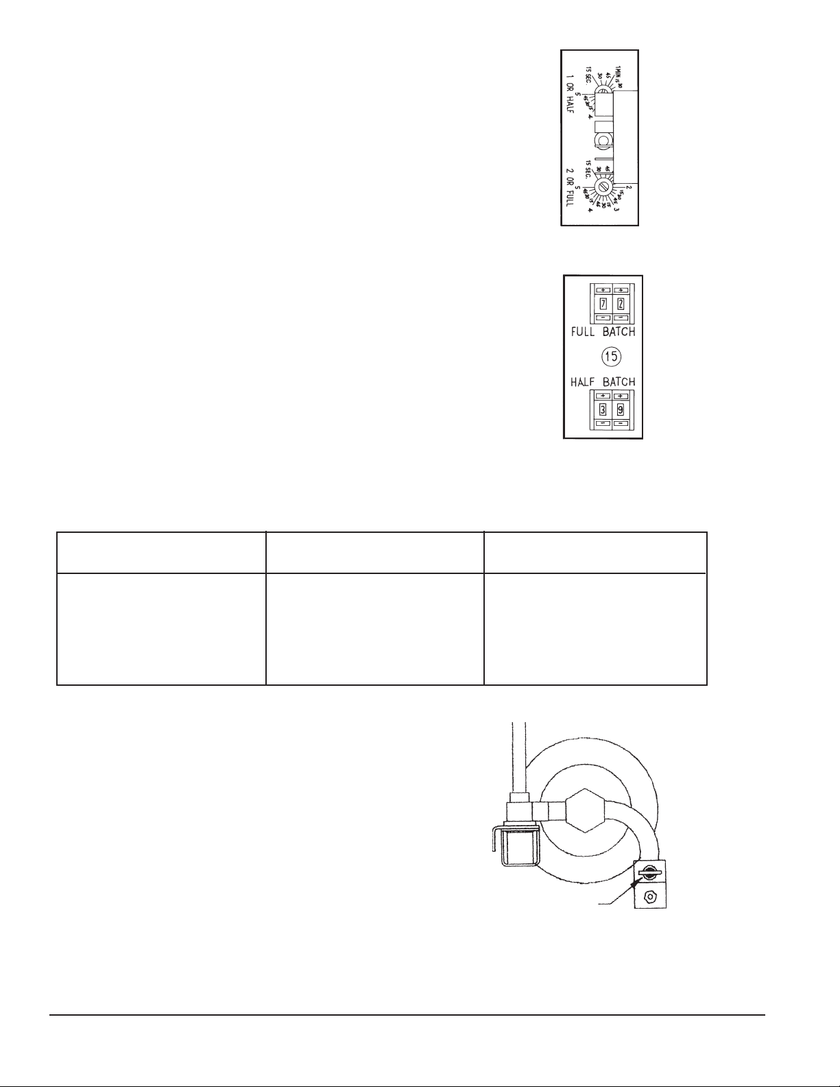
Two Batch Timer with Knob Adjustment, See Figure 2:
This timer is adjustable from 15 seconds to 5 minutes.
Locate the adjustment knobs under the top cover.
Set this timer by adjusting the knob. The batch selector
switch picks the adjustment potentiometer which the
timer will see.
Figure 2
Two Batch Timer
Two Batch Timer with Counter Adjustment, See Figure 3:
The two batch size timer may also be used with optional
counter potentiometer to ease adjustments. Each batch
size is adjustable from 00 to 99. The timer settings for this
timer are tabulated on the table below. This chart is for
making an approximate setting. You may need to click up or
down to make fine adjustments to volume. Each number
is about 3 seconds.
Figure 3
Two Batch Timer
w/Counter Adjustment
Counter Settings for NCC Q4F-0300-341AM Timers
Bypass Adjustment
The bypass valve adjusts the amount of water which
bypasses coffee grounds and dilutes the final brew
(see Figure 4). The factory setting is no bypass.
Bitter coffee results when the amount of ground
coffee is too small. Therefore, if your coffee is
brewing too strong, it is better to adjust the bypass
valve instead of reducing the amount of coffee.
Figure 4
Bypass Valve
Counter Time
Setting (min:sec)
35 2:03
40 2:17
45 2:31
50 2:45
55 2:59
60 3:13
Counter Time
Setting (min:sec)
65 3:26
70 3:39
75 3:53
80 4:06
85 4:20
99 5:00
BYPASS VALVE
Counter Time
Setting (min:sec)
00 0:15
10 0:46
15 1:01
20 1:17
25 1:32
30 1:47
BYPASS VALVE
Page 7
Shuttle Brewers & Airpot/Shuttle Brewers
To Adjust the Bypass:
1) Shut off and open brewer as described at the beginning of the adjustments section.
2) Locate the bypass valve for the brew head you wish to adjust. Valve is on the right and front
of the BREW valve.
3) Open the valve (counter clockwise) to the desired setting. Use the table below as a guide:
BYPASS SETTING BYPASS: % OF TOTAL BREW
closed 0
1 turn 8
2 turns 12
3 turns 22
4 turns 33
4) Measure the bypass setting:
a) Remove the brew basket.
b) Place an empty shuttle without its lid under the spray head.
c) Place a measuring cup under the bypass nozzle.
d) Press START and brew water for about thirty seconds or until measuring cup is almost
full. Press STOP.
e) Record the amount of water in the bypass measuring cup.
f) Add this to the water in the shuttle and record, measure the total amount of water.
g) The bypass percent is calculated as:
Bypass % = (Bypass Volume/Total Volume) X 100
5) Tweak the valve adjustment until the bypass is set as desired.
Note: The bypass is accurate to +
4%.
Thermostat Adjustment
The main thermostat adjusts the water temperature in the tank. Factory setting is 200°F. This
is the ideal temperature for brewing most coffee. Water should never boil in the tank. If water is
boiling, adjust the thermostat. There are two types of thermostats available. Mechanical is standard
and solid state is optional. See the adjustment instructions for the thermostat in your brewer.
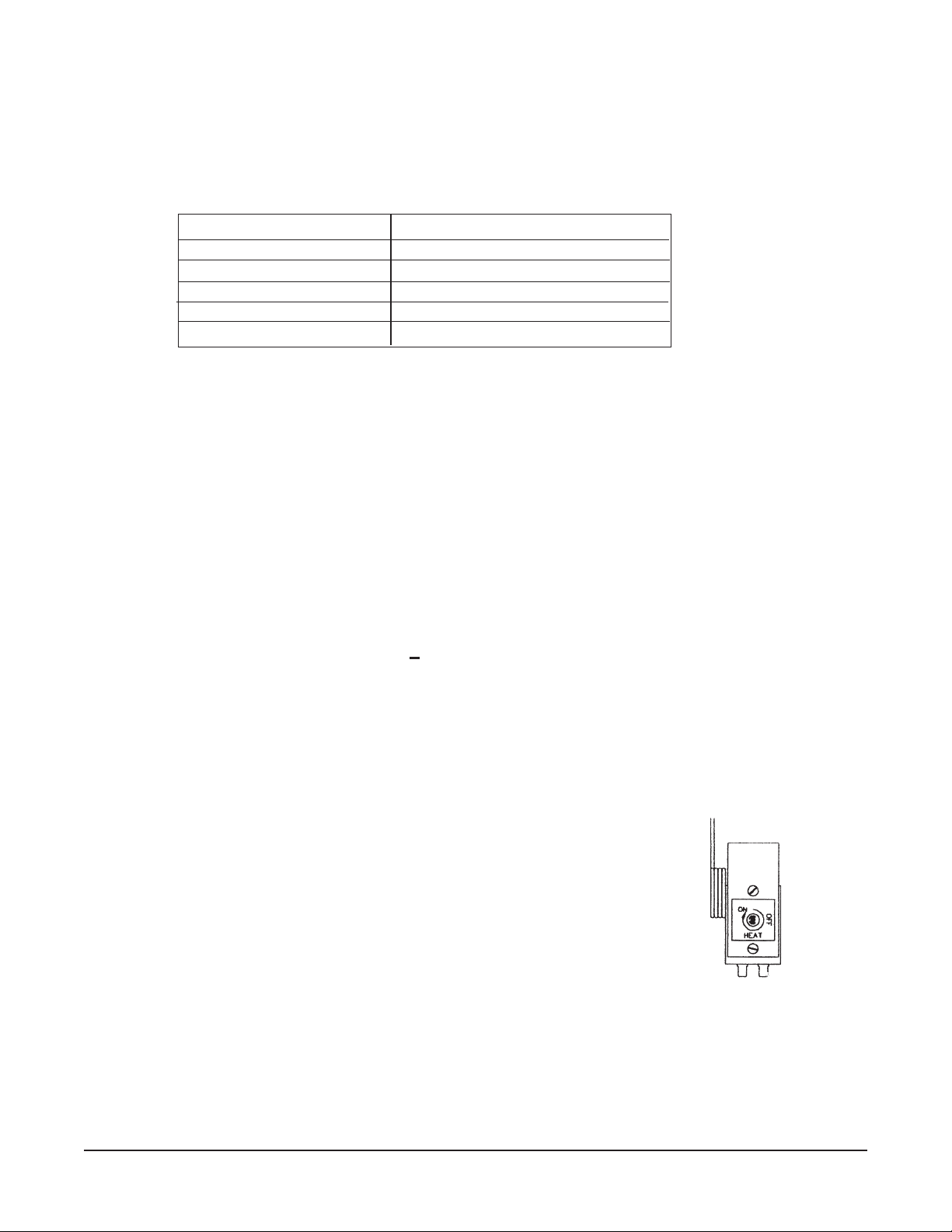
Standard Mechanical Thermostat:
1) Shut off power and open cover.
2) Locate thermostat mounted on tank. See Figure 5.
3) Turn the shaft counter clockwise to decrease temperature,
opposite to increase temperature.
Figure 5
Mechanical Ther mo stat
Page 8
Shuttle Brewers & Airpot/Shuttle Brewers
4) If the maximum temperature adjustment needs to be increased, insert a small flat screwdriver
into the shaft. Turn the calibration screw counter clockwise to increase the maximum
temperature.
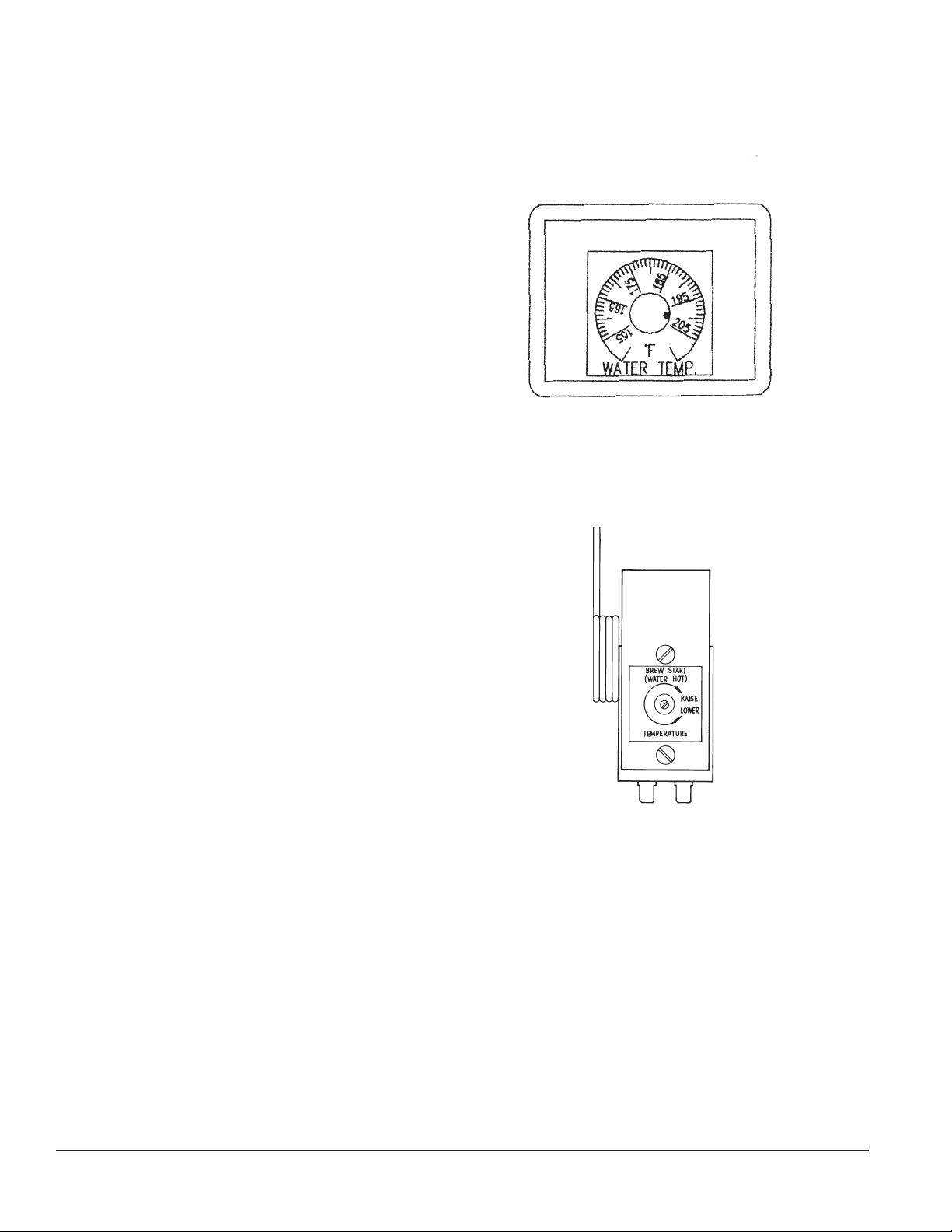
Optional Solid State Thermostat: This control maintains temperature within 3°F. The ad just able
range is from 155°F to 205°F.
See Figure 6.
1) Shut off power and open top cover.
2) Locate thermostat on bracket mounted
to front panel.
3) Adjust the knob to the temperature
desired. This control cannot be set
above 205°F.
Figure 6
Solid State Thermostat
Optional Brew Thermostat Adjustment: Your brewer may include the optional low temp/no brew
thermostat, (see Figure 7). This will not allow a brew unless the water is up to temperature. The
factory setting is 192°F. If you wish to adjust this, do the following:
1) Shut off power and remove top cover.
2) Locate the thermostat mounted on the
water tank.
3) To increase the set point, turn the shaft
clockwise. We do not recommend adjusting
this above 192°F which may cause
excessive delays between batches.
4) For accurate setting of the thermostat, remove
the bulb from the brewer and immerse in
water known to be 190°F. Adjust the
knob so the thermostat closes at this point.
Figure 7
Brew Thermostat

Page 9
Shuttle Brewers & Airpot/Shuttle Brewers
Cleaning
After Each Brew:
1) Dispose of grounds and rinse brew basket.
2) Rinse shuttle or airpot containers before reuse.
Every Day:
1) Wash brew basket with warm soapy water. The wire basket is removable to aid
cleaning.
2) Remove spray head(s), located above brew basket(s), using gloves or a heavy towel.
Wash off coffee oils and clean any plugged holes.
3) Clean shuttles with warm soapy water and a brush or towel.
4) Clean airpots with warm soapy water and bottle brush. Be careful, glass interior
breaks easily. Use only a soft cloth and warm soapy water or stainless steel polish
on the outside to avoid scratches.
5) Wipe exterior of brewer with a damp cloth. Do not use abrasives which will scratch
surface.
6) If shuttles are to be left on warmer all night, fill with water to avoid coffee oil burn-in.
WARNING
Burn Hazard!
Hot liquids and surfaces are present in this equipment. To avoid burns use caution when
cleaning. Rinse hot parts with cold water before cleaning. Use gloves or a heavy cloth when
removing hot parts from brewer.

Page 10
Shuttle Brewers & Airpot/Shuttle Brewers
Weekly or Bi-Weekly, Depending on Use
1) Fill shuttles with one gallon, 2/3 full, of hot water.
2) Pour into the shuttle liners the recommended concentration of urn cleaner (excessive amounts
of cleaner will attack the stainless steel).
Urn cleaners that have been used successfully:
DIP-IT, manufactured by Economics Laboratories, Inc.
4 Corporate Park Drive
White Plains, NY 10604
OXYLITE, manufactured by Avril, Inc., Syndet Division
601 N. Third Street
Reading, PA 19601
3) Scrub the liner interior with a plastic bristle brush.
4) Remove the knurled nut at the top of the gauge glass and clean the glass with a small
bottle brush.
5) Pour out the contents of the shuttle.
6) Remove the handle assembly of the shuttle faucet by unscrewing the plastic bonnet.
7) Gently wash the faucet seat cup with a soft cloth and warm soapy water.
8) Wash the faucet shank with a bottle brush.
9) Soak airpot pick-up tube assembly in hot soapy water. Urn cleaner may be used for
stronger cleaning.
10) Clean the warmer and bottom of shuttle surfaces. These surfaces must be clean for
proper heat transfer.
11) Polish the exterior of the brewer with stainless steel cleaner. Use the appropriate
cleaner for brass, copper, or vinyl if these optional finishes are provided.
Service
The rest of this manual contains information to aid the service person who is working on this equip ment.
This page has information on performing common service tasks. Following this is the Trou ble shoot ing
section which can help diagnose problems which are divided into three basic systems: filling, heating, and
brew ing.
Next is an illustrated parts breakdown which will help in the selection of repair parts. If further as sis tance
is needed, call our Technical Service Department at (502) 425-2776 or 800-695-4500 (USA & Canada
only) Monday - Friday between 8:00 am and 8:00 pm EST.
Wiring diagrams are also provided. Locate the basic diagram for the model you are working with. If
there are any options, see Diagram #091-548 (page 31 of this manual) which shows the wiring
alterations for Shuttle Brewer & Airpot/Shuttle Brewer options.

Page 11
Shuttle Brewers & Airpot/Shuttle Brewers
Service (con't)
Drain Water Tank
Always empty the tank before shipping.
Note: Brewer may contain over 5 gallons of hot water.
1) Prepare a heat resistant container to drain tank water into.
2) Shut off power to the brewer.
3) Remove the front access panel.
4) Pinch or clamp the silicone hose connected to fill valve.
5) Disconnect hose from outlet barb on fill valve.
6) Place hose over drain and release clamp.
7) Allow the tank to drain completely.
NOTE: It may be necessary to pinch the hose and stop the water before container is full. Carefully
reinstall hose over fill valve outlet, then empty container. Repeat steps 4-7 completely to drain tank.
Remove Brew Valve
1) Disconnect electric power to machine.
2) Remove top cover and remove wires and small tube from valve.
3) Tilt inlet of valve down and pull sideways out of spray tee.
4) Clamp rubber tubing and disconnect valve from tubing.
Remove Heater
1) Disconnect power and remove top cover of brewer.
2) Disconnect wire leads to heater.
3) Remove tank cover by loosening retaining screw. Cover is lifted up with heater attached.
Heater is then removed.
4) Replace heater with sealing washers in same configuration. When tightening nuts, hold
element so it does not twist.
5) Replace tank cover ensuring O-ring seal is good.
6) Replace heater wires. Be sure all electrical connections are secure.
WARNING
Draining of tank should be performed by a qualified service technician. The tank contains
very hot water. May cause severe burns.
 Loading...