


American Metal Ware PB-330, PB-430, PBVSA-330, PBVSA-430, PBIC-330 User Manual
...Shuttle® Brewer & Airpot/Shuttle® Brewers
Operation and Instruction Manual
For Models PB-330, PB-430, PBVSA-330, PBVSA-430, PBIC-330, PBIC-430,
PB330E 230V, PB-430E 230V, PBVSA-330E 230V,
PBVSA-430E 230V, PBIC-330E 230V, PBIC-430E 230V
Table of Contents |
|
|
|
Warning Labels . . . . . . . . . . . . . . . . . . . . . . . . . |
. 3 |
|
|
Installation and Start-up . . . . . . . . . . . . . . . . . . |
. 4 |
|
|
Operation . . . . . . . . . . . . . . . . . . . . . . . . . . . . . |
. 6 |
|
|
Adjustments . . . . . . . . . . . . . . . . . . . . . . . . . . . |
. 7 |
|
|
Programming . . . . . . . . . . . . . . . . . . . . . . . . . . |
10 |
|
|
Cleaning . . . . . . . . . . . . . . . . . . . . . . . . . . . . . . |
14 |
|
|
Service . . . . . . . . . . . . . . . . . . . . . . . . . . . . . . |
15 |
|
|
Precision Brew® Control Board . . . . . . . . . . . |
.16 |
|
|
Troubleshooting |
|
Models PB-330/PB-330E 230V |
Models PBIC-430/ |
Error Messages |
18 |
|
PBIC-430E230V |
|
|
||
Filling Problems . . . . . . . . . . . . . . . . . . . . . |
18 |
|
|
Heating Problems . . . . . . . . . . . . . . . . . . . . |
20 |
|
|
Brewing Problems . . . . . . . . . . . . . . . . . . . . |
22 |
|
|
Parts List . . . . . . . . . . . . . . . . . . . . . . . . . . . . . |
25 |
|
|
Parts Photos . . . . . . . . . . . . . . . . . . . . . . . . . . . |
26 |
|
|
VS-1.5(S) Cleaning and Sanitizing . . . . . . . . . . |
30 |
|
|
Wiring Diagrams . . . . . . . . . . . . . . . . . . . . . . . . |
31 |
|
|
|
|
|
|
Prior authorization must be obtained from |
Models PBVSA-430/ |
|
Grindmaster-Cecilware Corporation for all |
||
PBVSA-430E 230V |
||
warranty claims. |
||
|
Grindmaster Corporation
4003 Collins Lane Louisville, KY 40245 USA (502) 425-4776
(800) 695-4500 (USA & Canada only)
(800) 568-5715 (Technical Service Only) FAX (502) 425-4664 www.grindmaster.com
© Grindmaster Corporation, 2004 |
0210 Form # AM-344-07 |
PRINTED IN U.S.A. |
Part # A090-840 |
|

Warning Labels
The following warning labels were on your dispenser when it was shipped from the factory. They should remain on your dispenser in good, readable condition at all times. If one of your labels is missing or damaged, order a replacement label immediately.
Part # A546-445
Located on front splash panel and lid of machine.
Located on PB-330, PB-330E 230V, PB-430, and PB-430E 230V lower front decal.
Order part # A546-434 for PB-330. Order part # A546-435 for PB-430.
Located on PBIC-330, PBIC-330E 230V, PBIC-430, and PBIC-430E 230V above faucet.
Order part # A546-428 for PBIC-330. Order part # A546-427 for PBIC-430.
Part # A546-213
Located on front splash panel.
Part # A71949
Located on brew baskets.
 CAUTION
Hot liquid in brew basket could cause burns.
Remove with care.
Shuttle Brewers & Airpot/Shuttle Brewers |
Page 3 |

Installation
WARNING
ELECTRIC SHOCK HAZARD!
Installation of this appliance should be performed by qualified service personnel only. Improper installation could result in electrocution.
Set-Up/Position
1)Remove the brewer from the packing material and attach its legs.
2)Position the brewer on a strong, stable table or counter. Check the level front to back and side to side. Adjust the legs to the correct level.
IMPORTANT:
THE PERSON INSTALLING THIS APPLIANCE IS RESPONSIBLE FOR ENSURING THAT ELECTRIC AND WATER CONNECTIONS MEET THE REQUIREMENTS OF THE NATIONAL ELECTRIC CODE, NATIONAL PLUMBING CODE, AND ANY LOCAL ORDINANCES.
The electric and water hook-up locations are behind the front panel. Remove the four screws fastening this panel for access to these connections.
Water Hook-up
1)The water line may enter through holes on the rear or the bottom of the brewer. Use the right hand opening for water.
2)Use 3/8” copper or flexible water line to prevent strain. Do not use low temperature plastic tubing. The connection to the fill valve is 3/8” flare.
3)Water line pressure must be from 30 to 80 psi (207-2 KPA).
4)Hot (up to 160°F/71°C) or cold water may be used. Hot water offers faster recovery between brews.
5)Install a shut-off valve near the brewer.
6)Installing a filtering system can improve the taste of brewed coffee and extend the life of the brewer. If your water has high calcium (lime), chlorine, or iron content, this is especially important. The filter should be the lime inhibiting type if cold water is used.
Page 4 |
Shuttle Brewers & Airpot/Shuttle Brewers |
Installation (cont.)
Electric Hook-up
The brewer is designed to operate at the specified voltage on the nameplate with a tolerance of ± 10% for voltage deviation. It is very important that the power line to the brewer be checked to make sure that the voltage is within 10% of the brewer’s rated voltage. Failure to provide adequate voltage, as defined above, will cause problems with your brewer. If the power is too low, the solenoid valves may or may not work or longer recovery time will be experienced. The brewer may be permanently damaged if the voltage is too high.
1)The electric ratings for your brewer are printed on its nameplate.
2)The brewer should be connected to its own circuit with a fused disconnect switch or a circuit breaker near the brewer.
Important: For CE units, means shall be provided to endure all pole disconnection from the supply. Such means shall be one of the following: a supply cord fitted with plug, or a switch that is directly connected to the supply terminals and has a contact separation of at least 3mm in each pole.
3)Attach the appropriately sized cord to the brewer with a cord grip for the 1 1/2” (3.8 cm) electric input opening. The cord may enter through the rear or bottom on the left side of the brewer. Use an oil resistant cord such as type SO, SOO, SAO, STOO, SEO, SJO, SJOO, SJTO, SJTOO, SJEO, HSO, HSOO, HSJO, or HSJOO.
Alternatively, flexible conduit and type THHN wires may be used. Use only copper conductors.
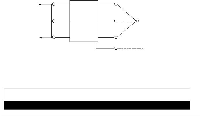
4)Standard connection is 1 phase 3 wire. Connect the two lines to L1 and L2 on the terminal block. If the brewer is wired for three phase, a lug, L3, is provided on the terminal block. Neutral line should be connected to the N terminal. Alternately, if no neutral is available, the brewer can be wired accordingly by connecting L1 to position marked “L1” and L2 to position marked “L2”. This will require the installer to change the connection to the transformer primary from the white wire (120V) to the blue (208V) or orange (230,240V) connection. See below.
NOTE: This “no neutral” conversion is only applicable to units marked as 208V, 230V, or 240V. It is NOT applicable to units marked 120/208V or 120/240V.
Note: The brewer utilizes a multiple tap primary transformer to convert line voltage to 24 volts for use by the controller and some operating controls. The transformer has taps for 120V (white wire), 208V (blue wire), and 240V (orange wire) line voltage. Be sure to connect the white wire from the terminal block to the proper tap for the supplied voltage.
See diagram below.
|
YELLOW |
ORANGE |
|
|
|
240V |
|
TO |
RED |
TRANSFORMER BLUE |
WHITE FROM |
CONTROLLER |
|
208V |
|
|
|
|
TERMINAL BLOCK |
|
|
|
*N-120V |
|
YELLOW |
WHITE |
*L2 -208V or 230V |
|
|
||
|
|
120V |
|
|
|
BLACK |
FROM L1 |
5) The body of the brewer must be grounded. A ground lug is provided for this purpose.
Note: If supply cord is damaged, it must be replaced by a special cord or assembly from the manufacturer, or it’s service agent.
Note: This appliance is IP10 rated, and shall not be cleaned with a water jet.
WARNING
Never use the ground conductor as a neutral. This could cause electrocution.
Shuttle Brewers & Airpot/Shuttle Brewers Page 5

Installation (cont.)
Start-up
1)Flip power supply to machine “ON” at the branch supply disconnect and allow the water tank to fill. The machine will make a subtle hissing sound while filling.
Attention: A watchdog circuit monitors the fill valve “ON” time. If the “ON” time exceeds 6 minutes continuously, the brewer will display message “ER1” and cease operation. Normal initial fill time on some models exceeds 6 minutes. Turn off power to brewer and turn back on; this will reset the controller and allow brewer to complete filling.
2)Once the brewer is full, it will take 15 to 35 minutes to heat. The ready lights will turn on when up to temperature.
3)Insert the brew baskets and place a Shuttle or airpot under the baskets. Brew at least one batch from each side. Check the level in the container to be sure the brew volume is correct. Remember that when using coffee, the level will be lower. Do this for all batch sizes. The water must be hot to check the levels. If adjustments are needed, see the adjustments section of this manual.
Operation
CAUTION
HOT LIQUID HAZARD!
Water used for brewing coffee is very hot. Use caution when brewing, pouring, or transporting coffee. Accidental spills may result in severe burns.
1)Place an empty, warm Shuttle on the shelf, under the brew head. Turn on the warmer if available.
2)If the Shuttle is not warm, allow the warmer to heat the Shuttle. Only a short brew of water will speed this. A cold Shuttle will significantly lower the temperature of the brewed coffee.
3)Remove the filter basket and line with a filter paper. Paper size is 13 x 5 for the smaller basket, BB1.5, and 14 x 6 for the larger, BB2.0.
4)Place ground coffee in the filter basket. Follow corporate recommendations for amount of coffee and grind. A full Shuttle is 1.5 gallons (5.7L). A full vacuum Shuttle is 1.6 (6.0L) gallons.
5)Slide the basket into the brewer making sure the spout lines up with the top of the Shuttle.
6)If ready lights are lit, press correct batch size button.
7)Brew spray time is about 4 minutes for a full Shuttle. After the brew, allow the coffee to drip for 1 to 2 minutes. Ready light will flash during the entire brew spray and drip cycle. Brew basket will be locked in place until drip cycle is finished.
CAUTION
Coffee basket contains very hot water until the drip is completed. Early removal of a dripping basket could result in burns.
8)Dump the grounds from the basket and rinse for the next brew. Coffee is ready to serve.
9)The Shuttle may be placed on remote warming stations. Use caution when moving a full Shuttle.
Page 6 |
Shuttle Brewers & Airpot/Shuttle Brewers |

Adjustments
All adjustments to machine are accessible through the front display(s). Refer to specifics below and the Programming Routine section. All values are preset at the factory and may vary brewer to brewer.
Temperature Adjustment
Tank temperature can be adjusted from 170°F – 205°F (77°C – 96°C) through the front display. See Programming Routine section for procedure.
This brewer can be set for maximum water temperature of 205°F (96°C). The boiling point of water is lower as altitude increases. The setpoint temperature of the brewer should be maintained below the boiling point at a given elevation. Refer the to the chart below for recommended maximum setpoint for given altitudes.
Altitude (ft) |
Approximate Boiling Point |
Recommended Max. Temperature |
|||
|
|
|
|
||
°F |
°C |
°F |
°C |
||
|
|||||
|
|
|
|
|
|
0 |
212 |
100 |
205 |
96.1 |
|
|
|
|
|
|
|
500 |
211.1 |
99.5 |
204 |
95.6 |
|
|
|
|
|
|
|
1000 |
210.2 |
99.0 |
203 |
95.0 |
|
|
|
|
|
|
|
1500 |
209.3 |
98.5 |
202 |
94.4 |
|
|
|
|
|
|
|
2000 |
208.4 |
98.0 |
201 |
93.9 |
|
|
|
|
|
|
|
2500 |
207.5 |
97.5 |
200 |
93.3 |
|
|
|
|
|
|
|
3000 |
206.6 |
97.0 |
199 |
92.8 |
|
|
|
|
|
|
|
3500 |
205.7 |
96.5 |
199 |
92.8 |
|
|
|
|
|
|
|
4000 |
204.8 |
96.0 |
198 |
92.2 |
|
|
|
|
|
|
|
4500 |
203.9 |
95.5 |
197 |
91.7 |
|
|
|
|
|
|
|
5000 |
203 |
95.0 |
196 |
91.1 |
|
|
|
|
|
|
|
5500 |
202 |
94.4 |
195 |
90.6 |
|
|
|
|
|
|
|
6000 |
201.1 |
93.9 |
194 |
90.0 |
|
|
|
|
|
|
|
6500 |
200.2 |
93.4 |
193 |
89.4 |
|
|
|
|
|
|
|
7000 |
199.3 |
92.9 |
192 |
88.9 |
|
|
|
|
|
|
|
7500 |
198.3 |
92.4 |
191 |
88.3 |
|
|
|
|
|
|
|
THERMISTOR CURVE FOR PART # A725-097
°C |
°F |
RESISTANCE (OHMS) |
|
°C |
°F |
RESISTANCE (OHMS) |
|
|
|
|
|
|
|
0 |
32 |
16325 |
|
60 |
140 |
1244 |
|
|
|
|
|
|
|
5 |
41 |
12697 |
|
65 |
149 |
1041 |
|
|
|
|
|
|
|
10 |
50 |
9951 |
|
70 |
158 |
875 |
|
|
|
|
|
|
|
15 |
59 |
7856 |
|
75 |
167 |
740 |
|
|
|
|
|
|
|
20 |
68 |
6246 |
|
80 |
176 |
628 |
|
|
|
|
|
|
|
25 |
77 |
5000 |
|
85 |
185 |
535 |
|
|
|
|
|
|
|
30 |
86 |
4028 |
|
90 |
194 |
458 |
|
|
|
|
|
|
|
35 |
95 |
3266 |
|
95 |
203 |
393 |
|
|
|
|
|
|
|
40 |
104 |
2663 |
|
100 |
212 |
339 |
|
|
|
|
|
|
|
45 |
113 |
2185 |
|
105 |
221 |
294 |
|
|
|
|
|
|
|
50 |
122 |
1802 |
|
110 |
230 |
255 |
|
|
|
|
|
|
|
55 |
131 |
1493 |
|
|
|
|
|
|
|
|
|
|
|
Shuttle Brewers & Airpot/Shuttle Brewers |
Page 7 |

Adjustments (cont.)
Brew Volume “br”
Brew time can be set for each size visually. See Setting Brew Volume Procedure below. Brew time can also be adjusted through the display. See Programming Routine section.
Setting Brew Volume Visually
1.Remove brew basket and place container under brew head.
2.Press and hold desired brew button for 5 seconds. Display will read “Pro”.
3.Within 20 seconds, press and release desired brew button. Water will dispense from spray head and time will count-up in display.
4.When volume is at desired amount, press and release brew button to stop flow. Time will flash in display.
5.Within 20 seconds, press and release desired brew button. Display will clear and brew time will be stored into memory.
Note: During this routine, no pulsing or bypass will occur.
Note: If the On/Off button is pressed during procedure, time setting will default to previous time.
Pulse Brewing “P-b”
Within the Programming Routine, the number of pulses, pulse-on-time, and pulse-off-time for each size brew cycle can be set. During the pulse-off cycle, water shuts off to the coffee grounds. During this period, the grounds in the brew basket absorb water causing the coffee bed to rise. With a larger bed of coffee in the brew basket, remaining water from spray head has more contact area with grounds causing greater extraction of finished coffee.
Note: Adjusting pulse values will not affect the finished brew volume. The brew time, however, will be automatically extended by the amount of total pulse OFF time.
See Brew Routine Section for examples.
Ratio “rto”
The ratio of the bypass flow rate versus the spray head flow rate is factory set. This number, however, rarely needs to be adjusted.
To find the proper value for the ratio:
1.Within the Programming Routine, set the bypass % to the maximum number allowable.
2.Remove the brew basket.
3.Prepare two containers to measure volume from both the spray head and bypass.
4.Press “Large” brew button to begin dispensing water.
5.After a minute or two, cancel the brew cycle by pressing the “Large” brew button or pressing the On/Off button.
6.Measure the volume of both containers.
7.Divide the bypass amount by the spray head amount. This number is to be entered as the new ratio (ex. “.45”).
8.Access the settings routine and adjust to the new ratio number.
Note: If the ratio number is accurate, changing the bypass percent will not require resetting brew time.
Note: Approximate ratio numbers:
.45 for standard spray head models
.64 for gourmet spray head models
Page 8 |
Shuttle Brewers & Airpot/Shuttle Brewers |

Adjustments (cont.)
Bypass “b-P”
Brewer contains a bypass valve to control the amount of water to bypass coffee grounds and dilute the final brew. Bypass is available on Large and Medium brew cycles.
Within the Programming Routine, the percent of the total brew volume to be bypassed can be set.
Note: Adjusting bypass percent will not affect the finished brew volume. The brew cycle time, however, will be automatically reduced as bypass percent increases.
Brew Routine
No Pulse Brewing or Bypass
Assumptions: “br” = 4.00, “P-b” = OFF, “b-P” = OFF
11. Press “Brew” button.
12. 0:00, Brew Valve opens and Ready Light flashes. 13. 4:00, Brew Valve closes.
14. 5:30, Ready Light stops flashing
Pulse Brewing ON, Bypass OFF
Assumptions: “br” = 4.00; “P-b” = 3, 20, 15; “b-P” = OFF
11. Press “Brew” button.
12. 0:00, Brew Valve opens and Ready Light flashes. 13. 0:20, Brew Valve closes. (Pulse #1)
14. 0:35, Brew Valve opens.
15. 0:55, Brew Valve closes. (Pulse #2)
16. 1:10, Brew Valve opens.
17. 1:30, Brew Valve closes. (Pulse #3)
18. 1:45, Brew Valve opens.
19. 4:45, Brew Valve closes.
10. 6:15, Ready Light stops flashing.
Pulse Brewing OFF, Bypass ON
Assumptions: “br” = 4.00; “P-b” = OFF; “rto” = 0.45; “b-P” = 20 (max 31)
(Software calculates: Brew valve-on-time = 192 sec and Bypass Valve-on-time = 107 sec)
11. Press “Brew” button.
12. 0:00, Brew Valve opens and Ready Light flashes. 13. 1:25, Bypass Valve opens.
14. 3:12, both valves close.
15. 4:42, Ready Light stops flashing.
Pulse Brewing and Bypass ON
Assumptions: “br” = 4.00; “P-b” = 3, 28, 18; “rto” = 0.45; “b-P” = 30 (max 31)
(Software calculates: Brew valve-on-time = 168 sec and Bypass Valve-on-time = 160 sec)
11. Press “Brew” button.
12. 0:00, Brew Valve opens and Ready Light flashes.
3.0:08, Bypass valve opens
14. 0:28, Both valves closes. (Pulse #1)
15. 0:46, Both valves opens.
16. 1:14, Both valves closes. (Pulse #2)
17. 1:32, Both valves opens.
18. 2:00, Both valves close. (Pulse #3)
19. 2:18, Both valves open.
10.3:42, Both valves close.
11.5:06, Ready light stops flashing.
Shuttle Brewers & Airpot/Shuttle Brewers |
Page 9 |

Programming
(All values are preset at the factory and may vary brewer to brewer.)
Settings Routine
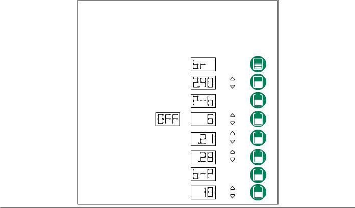
Programming For All Brewer Settings and Large Portion (refer to Table 1)
11. Press and hold both “up” and “down” arrows for 5 seconds. 12. All three “brew” lights will flash.
13. Press “Large Brew” button.
Only “Large” ready light illuminates during remaining steps.
14. Display will indicate either “d F” or “d C” (Fahrenheit or Celsius). Default is “d F”. 15. Press “up” or “down” arrow to change from one to another.
16. Press “Large Brew” button to accept and go to next setting.
17. Display will read temp value in the selected scale (170°F-205°F). Default is “200”. 18. Press “up” or “down” arrow to change value. (1° increments)
19. Press “Large Brew” button to accept and go to next setting.
10.Display will read “Br”. (Brew Time)
11.Press “Large Brew” button to go to next setting.
12.Display will read set brew time in minutes and seconds (0.01-6.00). Default is “4.00”.
13.Press “up” or “down” arrow to change value (1 second increments). (Approximately 0.8 oz./second.)
14.Press “Large Brew” button to accept and go to next setting.
15.Display will read “P-b”. (Pulse Brewing)
16.Press “Large Brew” button to accept and go to next setting.
17.Display will read “OFF” or “1” – “6” (number of pulses). Default is “1”.
18.Press “up” or “down” arrow to change value. (increments of 1)
19.Press “Large Brew” button to accept and go to next setting.
Note: If “OFF” is selected, skip pulse timing steps to #26.
20.Display will read “0.05” – “0.60” (pulse ON time for each pulse). Default is “0.40”.
21.Press “up” or “down” arrow to change value. (increments of one second)
22.Press “Large Brew” button to accept and go to next setting.
23.Display will read “0.05” – “0.60” (pulse OFF time for each pulse). Default is “0.40”.
24.Press “up” or “down” arrow to change value. (increments of one second)
25.Press “Large Brew” button to accept and go to next setting.
26.Display will read “rto” (bypass flow rate/spray head flow rate).
27.Press “Large Brew” button to go to next setting.
28.Display will read “0.20 – “1.25” (bypass rate/spray rate). Value is set at factory. If standard spray head, use “0.45, if gourmet or sealed use “0.64”.
29.Press “up” or “down” arrow to change value. (increments of 0.01)
30.Press “Large Brew” button to accept and go to next setting.
31.Display will read “b-P” (percent of brew volume to be bypassed).
32.Press “Large Brew” button to go to next setting.
33.Display will read “OFF” or “1” – “33” (bypass %). Default is 25.
34.Press “up” or “down” arrow to change value. (increments of one percent)
35.Press “Large Brew” button to accept and go to next setting.
36.Display will read “Ltn” (Low-Temp/No Brew).
37.Press “Large Brew” button to go to next setting.
38.Display will read “On” or “Off”. Default is “Off”.
39.Press “up” or “down” arrow to change value.
40.Press “Large Brew” button to accept and clear display.
Page 10 |
Shuttle Brewers & Airpot/Shuttle Brewers |
Programming For All Brewer Settings and Large Portion (cont.)
Table 1
1.PRESS-AND-HOLD UP & DOWN ARROWS FOR 5 SECONDS.
2.READY LIGHTS WILL FLASH.
3.PRESS BREW BUTTON FOR LARGE "L".
4.LARGE READY LIGHT FLASHES THROUGHOUT ROUTINE.
5.DISPLAY WILL READ AS FOLLOWS:
DISPLAY
READING ADJUST ADVANCE
TEMP SCALE |
OR |
TANK TEMP (170-205F) |
OR |
BREW TIME
BREW TIME (0:01-6:00) 4 minutes, 10 seconds shown
|
PULSE BREW |
|
# OF PULSES |
TO |
|
(OFF, 1 - 6) |
||
|
PULSE ON TIME (0:05-0:60)
# of seconds shown
PULSE OFF TIME (0:05-0:60)
# of seconds shown
BYPASS RATIO
BYPASS RATIO (0.20-1.25)
0.45 for Standard Spray Head, 0.64 for Gourmet Spray Head
BYPASS
BYPASS % (OFF, 1-33)
(MAX CHANGE DEPENDING ON RATIO)
LOW-TEMP/NO-BREW
LOW-TEMP/ |
OR |
|
NO-BREW |
||
|
Shuttle Brewers & Airpot/Shuttle Brewers |
Page 11 |
Programming (cont.)
Settings Routine
Programming For Medium: Brew Time, Pulse Brewing & Bypass (refer to Table 2)
11. Press and hold both “up” and “down” arrows for 5 seconds.
12. All three brew lights will flash.
13. Press “Medium Brew” button.
Only “Medium” ready light illuminates during remaining steps. 14. Display will read “Br” (Brew Time).
15. Press “Medium Brew” button to go to next setting.
16. Display will read set brew time in minutes and seconds (0.01-6.00). Default is “2.40”. 17. Press “up” or “down” arrow to change value. (1 second increments)
18. Press “Medium Brew” button to accept and go to next setting. 19. Display will read “P-b” (Pulse Brewing).
10.Press “Medium Brew” button to accept and go to next setting.
11.Display will read “Off” or “1” – “6” (number of pulses). Default is 2.
12.Press “up” or “down” arrow to change value (1 second increments). (Approximately 0.8 oz./second.)
13.Press “Medium Brew” button to accept and go to next setting.
Note: If “Off” is selected, skip pulse timing steps.
14.Display will read “0.05” – “0.60” (pulse ON time for each pulse). Default is “0.30”.
15.Press “up” or “down” arrow to change value. (increments of 1 second)
16.Press “Medium Brew” button to accept and go to next setting.
17.Display will read “0.05” – “0.60” (pulse OFF time for each pulse). Default is “0.30”.
18.Press “up” or “down” arrow to change value. (increments of 1 second)
19.Press “Medium Brew” button to accept and go to next setting.
20.Display will read “b-P” (percent of brew volume to be bypassed).
21.Press “Medium Brew” button to go to next setting.
22.Display will read “Off” or “1” – “33” (bypass %). Default is “OFF”.
23.Press “up” or “down” arrow to change value. (increments of 1 percent)
24.Press “Medium Brew” button to accept and clear display.
Table 2 |
1. PRESS-AND-HOLD UP & DOWN ARROWS FOR 5 SECONDS. |
||
|
2. READY LIGHTS WILL FLASH. |
||
|
3. PRESS BREW BUTTON FOR MEDIUM "M". |
||
|
4. MEDIUM READY LIGHT FLASHES THROUGHOUT ROUTINE. |
||
|
5. DISPLAY WILL READ AS FOLLOWS: |
||
|
DISPLAY |
||
|
READING ADJUST ADVANCE |
||
|
|
|
|
|
|
|
|
|
|
|
|
|
|
|
|
BREW TIME (0:01-6:00) 2 minutes, 40 seconds shown
PULSE BREW |
|
|
# OF PULSES |
TO |
|
(OFF, 1 - 6) |
||
|
PULSE ON TIME (0:05-0:60)
# of seconds shown
PULSE OFF TIME (0:05-0:60)
# of seconds shown
BYPASS
BYPASS % (OFF, 1-33)
(MAX MAY CHANGE DEPENDING ON RATIO)
Page 12 |
Shuttle Brewers & Airpot/Shuttle Brewers |
 Loading...