

Page 1
2012_04JPK
Instruction Manual
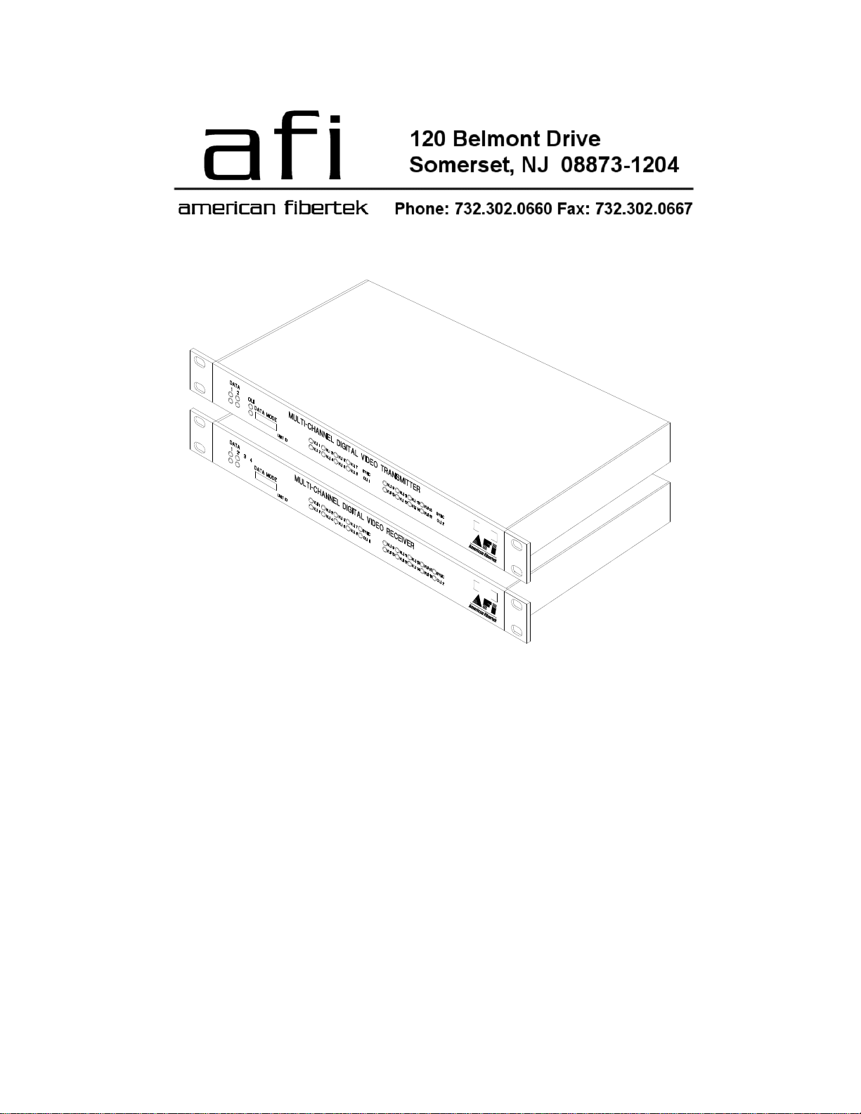
MTX-91685C
MRX-91685C
Sixteen Channel Video Multiplexer
With Two Bi-directional Data Channels
Page 2
Table of Contents
Functional Description ........................................................................3
Installation...........................................................................................3
Power Source .....................................................................................4
Fiber Connection .................................................................................4
Video Input / Output Connections.......................................................4
Data Input / Output Connections ........................................................5
Data Mode Switches...........................................................................5
Data Termination Requirements.........................................................6
MTX-91685 Status LED Indicators......................................................7
MRX-91685 Status LED Indicators.....................................................8
Warranty / Service Information .........................................................10
2
Page 3

INSTALLATION AND OPERATION INSTRUCTIONS
INTRODUCTION
Thank you for purchasing your American Fibertek Series 91685C multimode sixteen channel
video multiplexer with bi-directional multi-protocol data. Please take a few minutes to read these
installation instructions in order to obtain the maximum performance from this product.
FUNCTIONAL DESCRIPTION
The 91685C Series units operate as a transmitter / receiver pair for the digital transmission of
sixteen simultaneous NTSC or PAL video signals along with two channels of field configurable
bi-directional data over one multimode fiber optic cable. These data channels may be
configured as RS485 data, RS422 data, RS232 data, or Manchester data. The RS485 channel
may be configured for 2-wire (half duplex) or 4-wire (full duplex).
NOTE: This unit is shipped with Data Channel 1 and Data Channel 2 in the RS485 4-wire
configuration. For other configurations, please refer to the DATA CONFIGURATION
section for changes to the default switch settings.
The MTX-91685 transmitter accepts up to sixteen video inputs in two groups of eight videos and
multiplexes each group into a high speed serial data stream. The first group’s serial data
stream, along with the two forward data channels, modulates a laser at 1310nm wavelength.
The second group’s serial data stream modulates a laser at 1550nm. A Wave Division
Multiplexer (WDM) combines these two wavelengths, along with the return data wavelength of
850nm, onto a single optical output port for connection to the fiber transmission system.
Correspondingly, the MRX-91685 receiver converts the optical signal to sixteen independent
video output signals and two forward data signals while transmitting the two return data
channels.
The individual units may be configured for rack mounting or wall mounting depending upon the
position of the included mounting hardware. Nominal dimensions of the MTX-91685C and MRX91685C are 1 ¾ inches high by 17 inches wide by 11 ½ inches deep. When mounting hardware
is included, overall width increases to 19 inches wide.
INSTALLATION
THIS INSTALLATION SHOULD BE MADE BY A QUALIFIED SERVICE PERSON AND
SHOULD CONFORM TO THE NATIONAL ELECTRICAL CODE, ANSI/NFPA 70 AND LOCAL
CODES.
3
Page 4

To install the MTX-91685C or MRX-91685C it is first necessary to mount the rack flanges to the
unit.
For rack mounting the ears are installed on the
sides of the unit with the surfaces that have
oval holes flush with the front of the unit as in
Figure 1. Mount the ears with the #10 flathead
screws provided. To mount in the rack cabinet,
use mounting screws that are appropriate for
the rack cabinet being used. When mounting
the MTX-91685C or MRX-91685C in a rack
configuration, it is recommended that sufficient
airflow is available through the unit. This can
be achieved by leaving a 1RU slot above the unit open for air movement and by leaving open
space along the sides of the unit.
For mounting the unit flush to a wall or other rigid
surface, the ears may be installed on the sides
with the oval holes flush with the bottom of the unit
as in Figure 2. Mount the ears with the #10
flathead screws provided. Mount the unit to a rigid
surface using #10 (5mm) screws.
POWER SOURCE
The internal power supply accepts universal line voltage. Any mains supply from 100 to 240
VAC, 50 to 60 Hz, may be used without modification or adjustment. A universal power
connector is provided on the rear of the unit to facilitate connection to the power mains.
POWER CONNECTION
The unit is supplied with a three conductor power cord (US, UK, or Euro). The “ground”
conductor is directly connected to the chassis.
FIBER CONNECTION
The fiber optic connection is made via a ST connector located at the back of the unit. Be sure to
allow sufficient room for the required minimum bend radius of the fiber cable used.
VIDEO INPUT / OUTPUT CONNECTIONS
Video input and output connections are located on the rear of the unit. A BNC connector is
provided for each channel. The video inputs are connected to an appropriate 75 baseband
video source such as a camera or a video recorder output. The 75 video outputs can be
looped through typical baseband video inputs of switchers, recorders and other equipment as
required. For proper operation, the outputs must be terminated with 75. For optimum
performance the video cables should be the shortest length of coax practical.
4
Page 5

MTX-91685C DATA INPUT / OUTPUT CONNECTIONS
Data input and output connections are made via terminal blocks on the back of the unit. See the
drawings below for proper orientation of the input and output connections for each of the two
data channels.
MRX-91685C DATA INPUT / OUTPUT CONNECTIONS
Data input and output connections are made via terminal blocks on the back of the unit. See the
drawings below for proper orientation of the input and output connections for each of the two
data channels.
TYPICAL SYSTEM DATA CONNECTIONS
The connection terminalogy is based on industry standard EIA terminology for the transmission
of electronic data signals. Using this terminology, the driver of an electronic signal is labeled TX
or data out. Correspondingly, the receiver of an electronic signal is labeled RX or data in. Not all
manufactures follow standard EIA terminology. Consult the installation instructions for your
copper device if you are unsure which two wires are the drive (data out) wires and which two
wires are the receive (data in) wires. Please note that Data In on the MTX-91685C becomes
Data Out on the MRX-91685C after going across the fiber. The reverse flow follows the same
orientation.
DATA MODE
NOTE: This unit shipped with Data Mode switches in the RS485 4-wire position.
For other configurations of data channel 1 or data channel 2, please refer to the drawing below
for changes to the default switch settings. These configuration switches are located on the front
of the unit and can be modified without opening the unit. Please note that switch # 1 and switch
# 2 are not used and should remain in the off (up) position.
5
Page 6

DATA TERMINATION REQUIREMENTS
RS232 Data Signals
The RS232 interface standard is a point to point transmission protocol for digital signals. It
allows for a single transmitter device communicating to a single receiving device. This
configuration is mirrored in the opposite direction to create one bi-directional data path. Devices
using this protocol have terminating resistors built into their data path. This eliminates the need
for any switch selection for termination resistors in the RS232 mode.
RS422 Data Signals
The electrical interface described in RS422 is a data transmission standard for balanced digital
signals. It allows for a single transmitter device communicating to as many as 32 receiving
devices. This type of data signal is well suited to systems that require data to be distributed to
several points without a return data path. Several companies offer camera telemetry controllers
using this data interface. Because there is only one transmitting device on the network, this one
may remain active at all times. There is no need for the driver to go into a high impedance state
to allow others to "talk." In most cases termination resistors are not required to be applied to
RS422 data outputs. In long copper runs (over 500 feet) termination resistors may be required
on data inputs to eliminate data reflections.
RS485 Data Signals
RS485 differs from RS422 in the ability of the transmitter devices to go into a high impedance
(Hi-Z) state. This allows multiple transmitter devices to reside on the same wire pair. The
software must dictate a protocol that allows one device to transmit at any one time to prevent
data crashes. Data wiring can use two wires or four wires. Using two wires the system works in
half duplex. This means that data is exchanged between two points sequentially. When a fourwire system is used, the system may be full duplex. In many cases the system head end
controller will continuously poll data from all remote devices. The remote devices all respond
back to the head end (one at a time!) as they are addressed. This property of the network rests
solely in the hands of the software (firmware).
The driver chips used in RS485 communications are capable of changing into their high
impedance state very rapidly. On even short lengths of wire there can exist a residual voltage
after a driver circuit turns off. This can interfere with circuits that are used to detect the Hi-Z
state. It is very important that the copper communications lines be terminated with resistors
across the data wire pair. The best place to locate such resistors is at the furthest electrical
devices at the ends of the wire pair. For instance, if several RS485 devices are connected in a
daisy chain fashion, the wire connection would loop across all devices in a chain. The furthest
two points in the chain would need to be terminated with a 120 ohm resistor.
6
Page 7

MTX-91685C STATUS INDICATORS
The MTX-91685C transmitter provides the following front panel LED status indicators to aid in
installation and troubleshooting:
DATA RX/TX INDICATORS
DATA RX and DATA TX indicators are provided to monitor each of the two available data
channels. DATA 1 RX and TX correspond with the multi-protocol output/input of DATA CH 1.
DATA 2 RX and TX correspond with the multi-protocol output/input of DATA CH 2.
DATA RX
A green LED indicator is provided to monitor the data coming in from the fiber, through the
MTX-91685CC, and out onto the electrical interface. The intensity of this indicator will vary with
input data patterns, however in typical applications it will cycle on and off as data is received.
Data received status associated with this LED is summarized below.
DATA RX LED Data Status
Green Data Flow Present
Off Data Flow Not Detected
DATA TX
A green LED indicator is provided to monitor the data coming in from the electrical interface,
through the MTX-91685C, and out onto the fiber. The intensity of this indicator will vary with
input data patterns, however in typical applications it will cycle on and off as data is transmitted.
Data transmitted status associated with this LED is summarized below.
DATA TX LED Data Status
Green Data Flow Present
Off Data Flow Not Detected
VLI 1 THROUGH VLI 16
A bi-color LED indicator is provided for the each of the sixteen video inputs to the MTX-91685C.
Video status associated with each of these LED’s is summarized below.
Video Presence LED Video Status
Green Proper Input Video Present
Red Input Video Not Detected
OLI
A bi-color LED indicator monitors the optical input power of the data signal that is being
received at the MRX-91685C from the MTX-91685C. AC power and optical input status
associated with these LED’s are summarized in the following table.
7
Page 8

Green On Proper Optical Input Power Present
Red On Optical Input Not Detected
Off Off Check Power Supply Input
AC Power Status Optical Status
MRX-91685C STATUS INDICATORS
The MRX-91685C receiver provides the following front panel LED status indicators to aid in
installation and troubleshooting:
DATA RX/TX INDICATORS
DATA RX and DATA TX indicators are provided to monitor each of the two available data
channels. DATA 1 RX and TX correspond with the multi-protocol output/input of DATA CH 1.
DATA 2 RX and TX correspond with the multi-protocol output/input of DATA CH 2.
DATA RX
A green LED indicator is provided to monitor the data coming in from the fiber, through the
MRX-91685C, and out onto the electrical interface. The intensity of this indicator will vary with
input data patterns, however in typical applications it will cycle on and off as data is received.
Data received status associated with this LED is summarized below.
DATA RX LED Data Status
Green Data Flow Present
Off Data Flow Not Detected
DATA TX
A green LED indicator is provided to monitor the data coming in from the electrical interface,
through the MRX-91685C, and out onto the fiber. The intensity of this indicator will vary with
input data patterns, however in typical applications it will cycle on and off as data is transmitted.
Data transmitted status associated with this LED is summarized below.
DATA TX LED Data Status
Green Data Flow Present
Off Data Flow Not Detected
VLI 1 THROUGH VLI 16
A bi-color LED indicator is provided for the each of the sixteen video outputs of the MRX91685C. Video status associated with each of these LED’s is summarized below.
Video Presence LED Video Status
Green Proper Output Video Present
Red Output Video Not Detected
8
Page 9

SYNC
A bi-color LED indicator is provided to monitor the proper serialization of the electrical video
data stream through the MRX-91685C. A SYNC indicator for videos one through eight is located
above the OLI 1 indicator. A SYNC indicator for videos nine through sixteen is located above
the OLI 2 indicator. Sync status associated with these LED’s is summarized below.
Sync LED Sync Status
Green Proper Data Stream Serialization Present
Red Data Stream Serialization Not Detected
OLI 1
A bi-color LED indicator monitors the power of the optical input signal that is being received at
the MRX-91685C from video channels one through eight of the MTX-91685C. AC power and
optical input status associated with this LED are summarized below. Please note that data is
sent to the MRX-91685C with this optical input signal.
Optical Level Indicator AC Power Status Optical Status
Green On Proper Optical Input Power Present
Red On Optical Input Not Detected
Off Off Check Power Supply Input
OLI 2
A bi-color LED indicator monitors the power of the optical input signal that is being received at
the MRX-91685C from video channels nine through sixteen of the MTX-91685C. AC power and
optical input status associated with this LED are summarized below.
Optical Level Indicator AC Power Status Optical Status
Green On Proper Optical Input Power Present
Red On Optical Input Not Detected
Off Off Check Power Supply Input
9
Page 10

LIFETIME WARRANTY INFORMATION
American Fibertek, Inc warrants that at the time of delivery the products delivered will be free of
defects in materials and workmanship. Defective products will be repaired or replaced at the
exclusive option of American Fibertek. A Return Material Authorization (RMA) number is
required to send the products back in case of return. All returns must be shipped prepaid. This
warranty is void if the products have been tampered with. This warranty shall be construed in
accordance with New Jersey law and the courts of New Jersey shall have exclusive jurisdiction
over this contract. EXCEPT FOR THE FOREGOING WARRANTY, THERE IS NO WARRANTY
OF MERCHANTABILITY OR FITNESS FOR A PARTICULAR PURPOSE OR OTHERWISE,
EXPRESSED OR IMPLIED, WHICH EXTENDS BEYOND THE WARRANTY SET FORTH IN
THIS AGREEMENT. In any event, American Fibertek will not be responsible or liable for
contingent, consequential, or incidental damages. No agreement or understanding, expressed
or implied, except as set forth in this warranty, will be binding upon American Fibertek unless in
writing, signed by a duly authorized officer of American Fibertek.
SERVICE INFORMATION
There are no user serviceable parts inside the unit.
In the event that service is required to this unit, please direct all inquiries to:
American Fibertek, Inc. Phone: (877) 234-7200
120 Belmont Drive Phone: (732) 302-0660
Somerset, NJ 08873 FAX (732) 302-0667
E-mail: techinfo@americanfibertek.com
10
 Loading...