

Page 1
Illustra Flex Series
Installation and Configuration Guide
Page 2

Notice
Please read this manual thoroughly and save it for future use before attempting to connect or operate
this unit.
The information in this manual was current when published. The manufacturer reserves the right to
revise and improve its products. All specifications are therefore subject to change without notice.
Copyright
Under copyright laws, the contents of this manual may not be copied, photocopied, reproduced,
translated or reduced to any electronic medium or machine-readable form, in whole or in part, without
prior written consent of Tyco Security Products.
© 2018 Tyco Security Products. All rights reserved.
Tyco Security Products
6600 Congress Avenue
Boca Raton, FL 33487 U.S.A.
Customer Service
Thank you for using American Dynamics products. We support our products through an extensive
worldwide network of dealers. The dealer through whom you originally purchased this product is your
point of contact if you need service or support. Our dealers are empowered to provide the very best in
customer service and support. Dealers should contact American Dynamics at (800) 507-6268 or
(561) 912-6259 or on the Web at www.americandynamics.net.
Trademarks
The trademarks, logos, and service marks displayed on this document are registered in the United
States [or other countries]. Any misuse of the trademarks is strictly prohibited and Tyco Security
Products will aggressively enforce its intellectual property rights to the fullest extent of the law,
including pursuit of criminal prosecution wherever necessary. All trademarks not owned by Tyco
Security Products are the property of their respective owners, and are used with permission or
allowed under applicable laws.
Product offerings and specifications are subject to change without notice. Actual products may vary
from photos. Not all products include all features. Availability varies by region; contact your sales
representative.
Page 3

Table of Contents
Overview 8
Illustra Flex Series 3MP and 8MP Indoor Dome Camera 9
Product features 9
Product overview 9
Installation 13
Illustra Flex Series 3MP and 8MP Outdoor Dome Camera 17
Product features 17
Product overview 17
Installation 21
Illustra Flex Series 3MP and 8MP Outdoor Bullet Cameras 26
Product features 26
Product overview 26
Installation 30
Illustra Flex Series 3MP and 8MP Indoor Box Camera 35
Product features 35
Product overview 35
Installation 38
Illustra Flex 3MP Outdoor Compact Mini Dome Camera 40
Product features 40
Product overview 40
Installation 43
System requirements 49
Network Topology 50
Network Connection 54
Default IP Address 54
DHCP 55
Managing cameras with the Illustra Connect tool 56
Configuration 58
Page 4

Illustra Flex Series Installation and Configuration Guide
Live menu 61
Quick Start Menu 63
BasicConfiguration 63
Video Menu 81
Streams 81
Picture Settings 87
Date / Time / OSD 95
PrivacyZones 97
Events and Actions Menu 100
Event Settings 100
Event Actions 103
Alarm I / O 105
Analytics 107
Event Logs 110
Security 113
Security Status 113
Security Status 115
Users 116
HTTP / HTTPS 118
IEEE 802.1x 120
Firewall 121
Remote Access 123
Session Timeout 125
Network Menu 127
TCP/IP 127
Multicast 128
FTP 129
SMTP 131
SNMP 132
CIFS 133
Dynamic DNS 133
System 135
8200-1456-01 J0 4
Page 5

Illustra Flex Series Installation and Configuration Guide
Maintenance 135
Date / Time 138
Audio 139
Analog Video 141
Health Monitor 141
Logs 142
About 144
Edge Recording 145
Micro SD Card Management 145
Record Settings 147
Event Download 148
Appendix A: User Account Access 149
Appendix B: Using Media Player to View RTSP Streaming 151
Appendix C: Stream Table 152
Appendix D: Camera Defaults 155
End User License Agreement (EULA) 164
5 8200-1456-01 J0
Page 6

Illustra Flex Series Installation and Configuration Guide
Warning
• These units operate at AC 24V/ PoE (the Box camera also supports DC12V).
• Installation and service should be performed only by qualified and experienced technicians and comply with all
localcodes and rules to maintain your warranty.
• To avoid damage to the unit, never connect more than one type of power supply (PoE IEEE802.3 Ethernet Class
0) at the same time. If using PoE, this camera is to be connecting only to PoE networks without routing to
heterogeneous devices.
• The camera is not intended to be directly connected to an external network and the video coax connections
should only be connected intra-building.
• To reduce the risk of fire or electric shock, do not expose the product to rain or moisture.
• Wipe the camera with a dry soft cloth. For tough stains, slightlyapply with diluted neutral detergent and wipe with
a dry soft cloth.
• Do not apply benzene or thinner to the camera, which may cause the surface of the unit to be melted or lens to be
fogged.
• Avoid aligning the lensto very bright objects(for example, light fixtures) for long periods of time.
• ITE is to be connected onlyto PoE networks without routing to the outside plant.
• The power supply shall be approved for ITE NEC Class 2 or LPS with a rating of 24VAC, 550mA minimum and 50
degrees Celsius.The Compact Mini Dome power supply shall be approved for ITE NEC Class 2 or LPS, 550mA
minimum and 50 degrees Celsius.
• Video Out connection should be intra-building only.
• Avoid operating or storing the unit in the following locations:
• Extremely humid, dusty, or hot/cold environments. Recommended operating temperature is:
• Indoor Minidome: -20˚C to 50˚C (-4˚F to 122˚F)
• Outdoor Minidome: -50˚C to 50˚C (-58˚F to 122˚F )
• Bullet: -40˚C to 50˚C (-40˚F to 122˚F)
• Box: -20˚C to 50˚C (-4˚F to 122˚F)
• Compact Mini Dome: -40˚C to 50˚C (-40˚F to 122˚F)
• Power over Ethernet (PoE) does not support heater.
• Near sources of power ful radio or TV transmitters.
• Near fluorescent lamps or objects with reflections.
• Under unstable or flickering light sources.
6 8200-1456-01 J0
Page 7

Illustra Flex Series Installation and Configuration Guide
WEEE (Wast e Electrical and Electronic Equip ment). Correct disposalof this product (applicable in the European Union
and other European countries with separate collection systems). This product should be disposed of, at the end of its useful
life, as per applicablelocal laws, regulations, and procedures.
8200-1456-01 J0 7
Page 8
Illustra Flex Series Installation and Configuration Guide
Overview
This Illustra Flex Installation and Configuration Guide is a user manual which provides physical
properties, installation, and configuration information of the cameras in Table 1 on Page 8.
Table 1 Product codes
Product
Code
IFS03D1ICWTT
IFS03D1OCWIT
IFS03B1BNWIT
IFS03XNANWTT
IFS03CFOCWST
IFS08D2ICWTT
IFS08D2OCWIT
IFS08B2ONWIT
IFS08XNANWTT
Model Name Description
Illustra Flex 3MP
indoor dome
Illustra Flex 3MP outdoor dome
Illustra Flex 3MP bullet
Illustra Flex 3MP
box
Illustra Flex 3MP
Compact Mini Dome
Illustra Flex 4K
indoor dome
Illustra Flex 4K outdoor dome
Illustra Flex 4K bullet
Illustra Flex 4K box
Illustra Flex 3MP Mini-dome, 2.8-12mm, indoor,
vandal, clear, white, TDN, TWDR
Illustra Flex 3MP Mini-dome, 2.8-12mm, outdoor,
vandal, clear, white, TDN w/IR, TWDR
Illustra Flex 3MP Bullet, 2.8-12mm, outdoor, nonvandal, white, TDN w/IR, TWDR
Illustra Flex 3MP Box, no lens, indoor, nonvandal, white, TDN, TWDR
Illustra Flex 3MP Compact Dome, 2.8mm, outdoor, vandal, clear, white, SDN, TWDR
Illustra Flex 8MP Mini-dome, 3.4-9mm, indoor,
vandal, clear, white, TDN, TWDR
Illustra Flex 8MP Mini-dome, 3.4-9mm, outdoor,
vandal, clear, white, TDN w/IR, TWDR
Illustra Flex 8MP Bullet, 3.4-9mm, outdoor, nonvandal, white, TDN w/IR, TWDR
Illustra Flex 8MP Box, no lens, indoor, nonvandal, white, TDN, TWDR
The first portion of this guide contains information pertaining specifically to the aforementioned
cameras.
• For the Illustra Flex 3MP and 8MP Indoor Dome camera, refer to Illustra Flex Series
3MP and 8MP Indoor Dome Camera on page 9.
• For the Illustra Flex 3MP and 8MP Outdoor Dome camera, refer to Illustra Flex Series
3MP and 8MP Outdoor Dome Camera on page 17.
• For the Illustra Flex 3MP and 8MP Bullet camera, refer to Illustra Flex Series 3MP and
8MP Outdoor Bullet Cameras on page 26.
• For the Illustra Flex 3MP and 8MP Box camera, refer to Illustra Flex Series 3MP and
8MP Indoor Box Camera on page 35.
• For the Illustra Flex 3MP Outdoor Compact Mini Dome camera, refer to Illustra Flex
3MP Outdoor Compact Mini Dome Camera on page 40.
The second portion of this guide contains information regarding the Illustra User Web Interface and
the web configuration of the aforementioned cameras. Refer to Configuration on page 58 for
procedural information pertaining to camera configuration.
8 8200-1456-01 J0
Page 9
Illustra Flex Series Installation and Configuration Guide
Illustra Flex Series 3MP and 8MP Indoor Dome
Camera
This chapter provides product features, installation procedures, and connection information regarding
the Illustra Flex Series Indoor Dome cameras.
Product features
Len cases require special care when handling and cleaning to avoid scratches. For information on
bubble handling and cleaning, see 8200-1174-01 Bubble Clearing Procedure Application Note.
Go to https://illustracameras.com/products.
From the Products page, select your camera product range and then select your camera model. Click
Downloads and search for Bubble Handling and Cleaning Procedure.
Product overview
This chapter explains the features and installation of the Illustra Flex Indoor Dome cameras. Product
code and description of the camera is provided in the table below.
Table 2 Product code and description of the Illustra Flex Indoor Dome camera
Product
Code
IFS03D1ICWTT
IFS08D2ICWTT
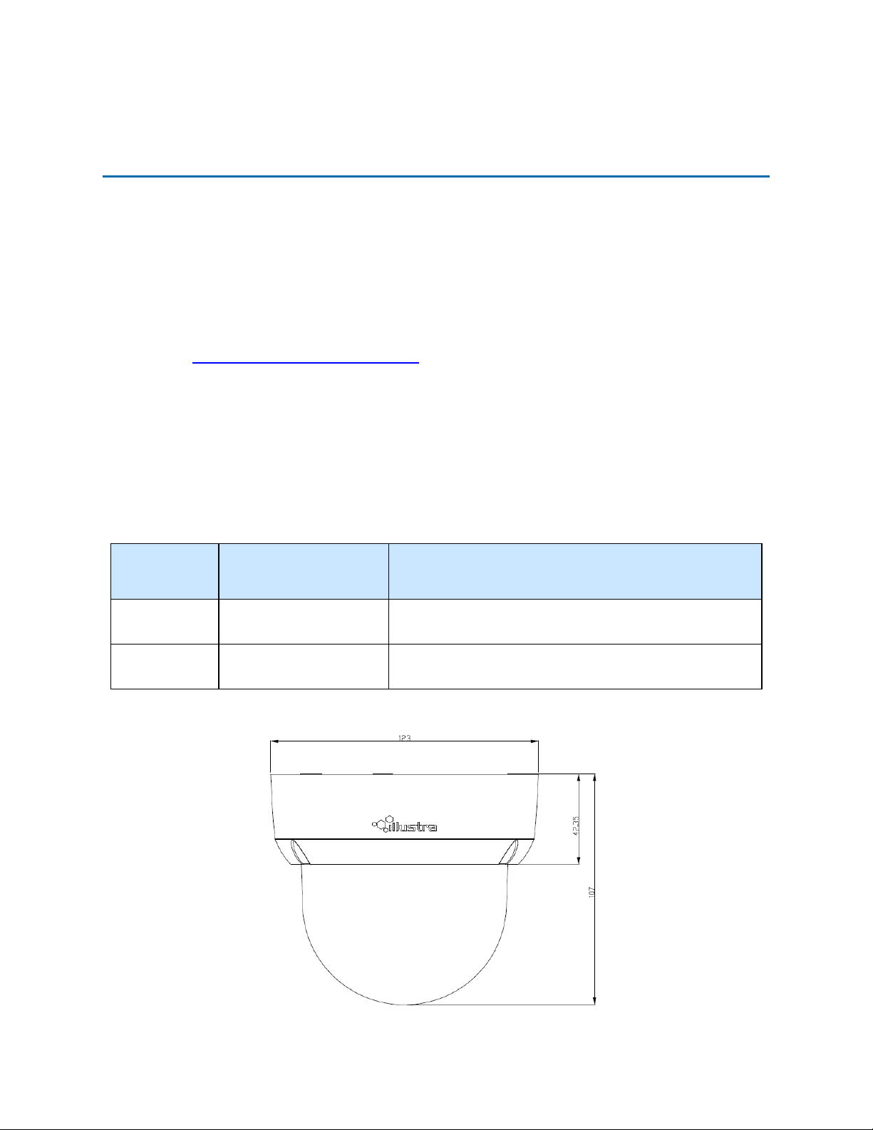
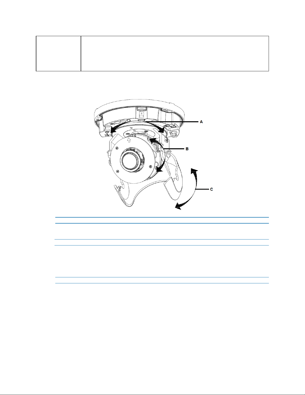
Figure 3 Physical dimensions of the Illustra Flex Indoor Dome camera (mm)
Model Name Description
Illustra Flex 3MP Indoor
Mini-Dome
Illustra Flex 4K Indoor
Mini-Dome
Illustra Flex 3MP Mini-dome, 2.8-12mm, indoor, vandal, clear,
white, TDN, TWDR
Illustra Flex 8MP Mini-dome, 3.4-9mm, indoor, vandal, clear,
white, TDN, TWDR
9 8200-1456-01 J0
Page 10
Illustra Flex Series Installation and Configuration Guide
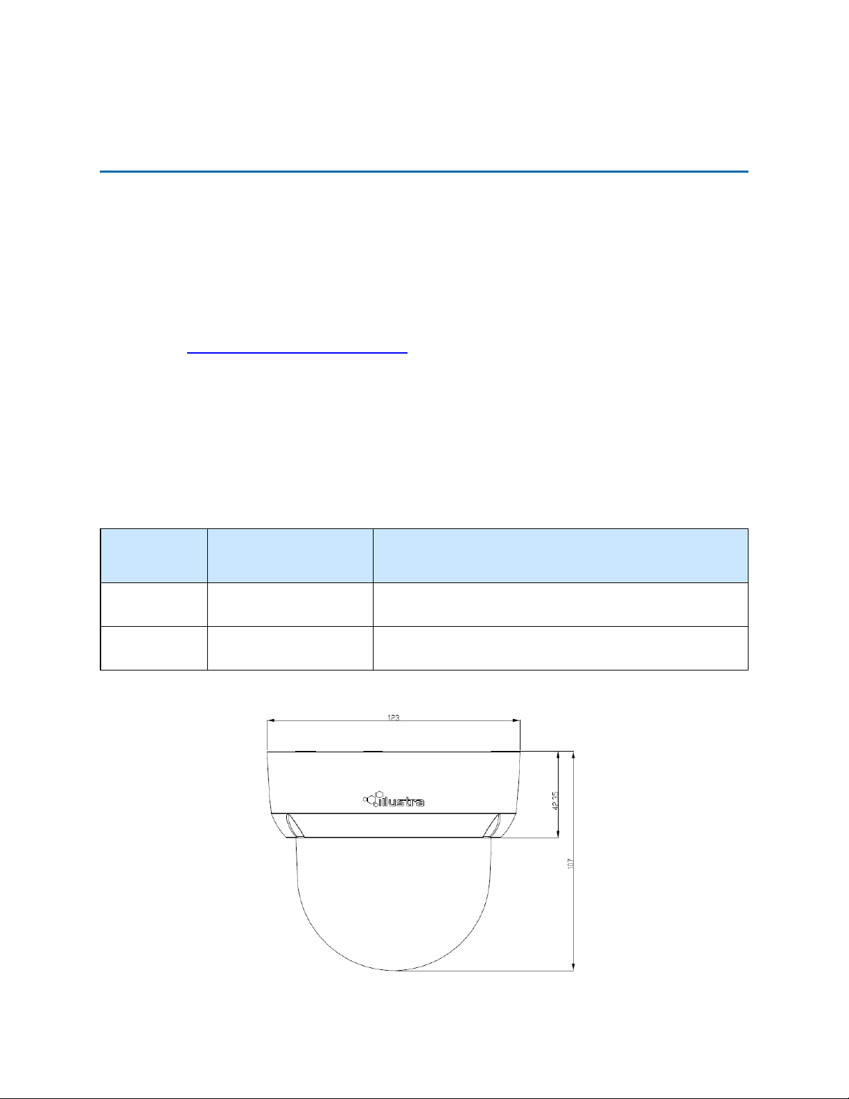
Figure 4 Physical dimensions of the Illustra Flex Indoor Dome camera
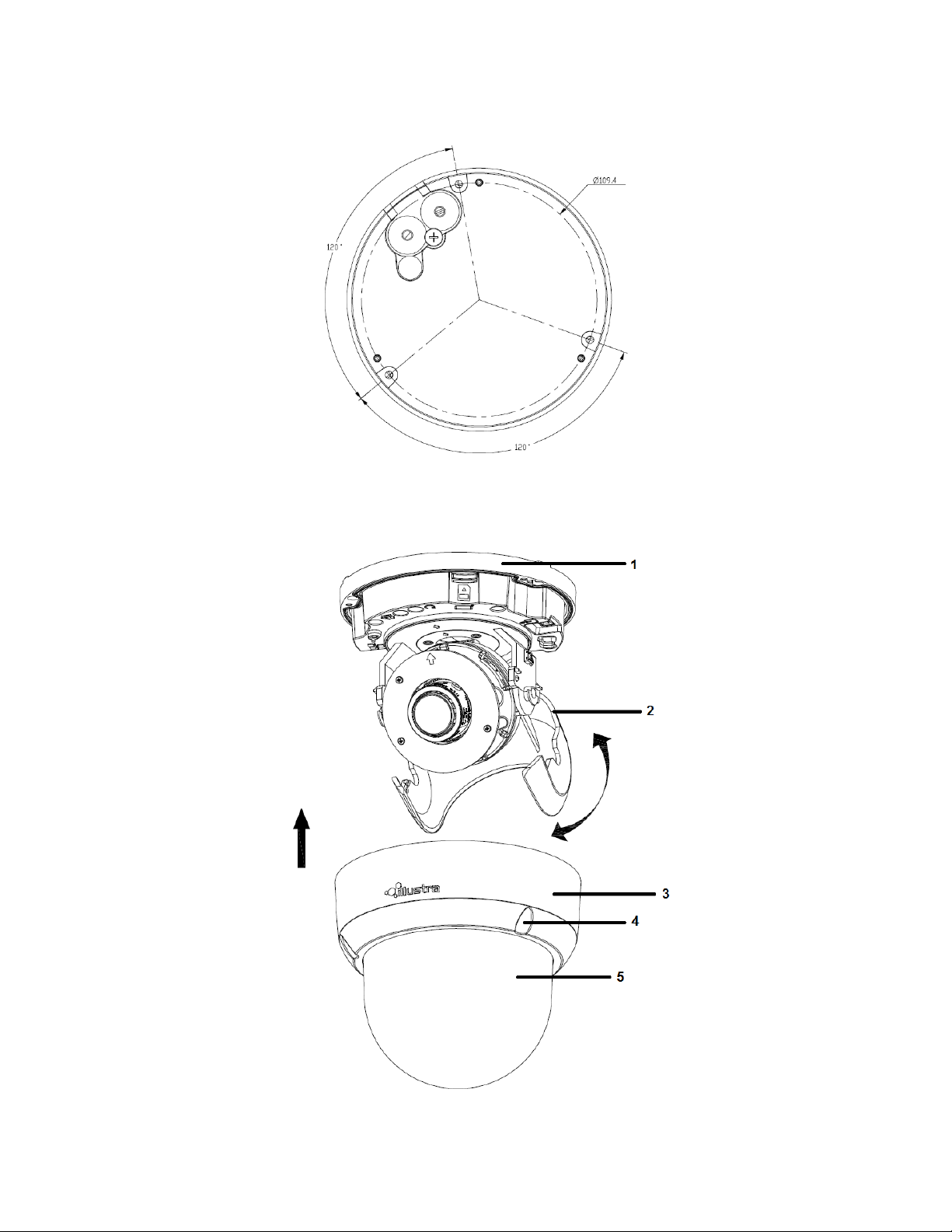
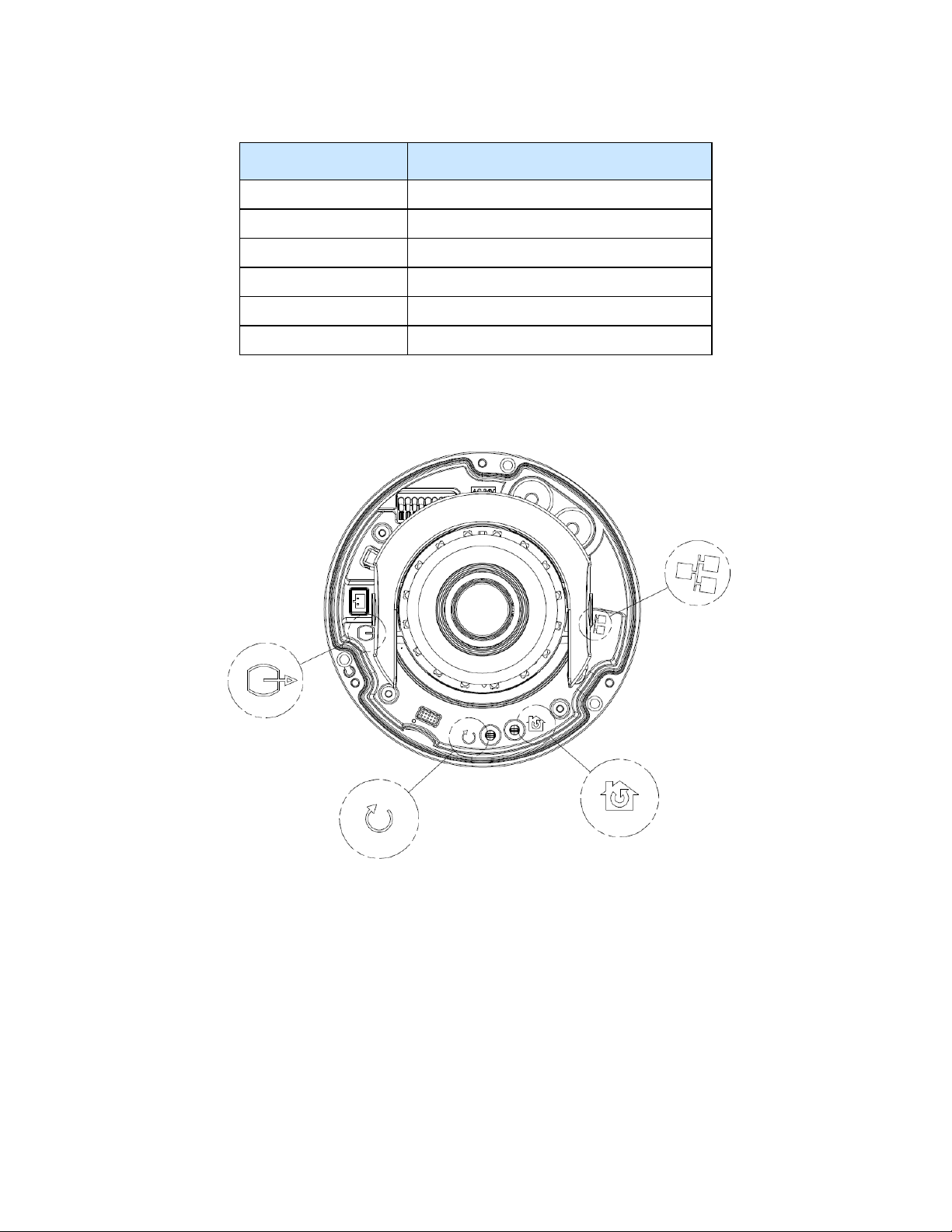
Figure 5 Pictorial index of the camera
8200-1456-01 J0 10
Page 11
Illustra Flex Series Installation and Configuration Guide
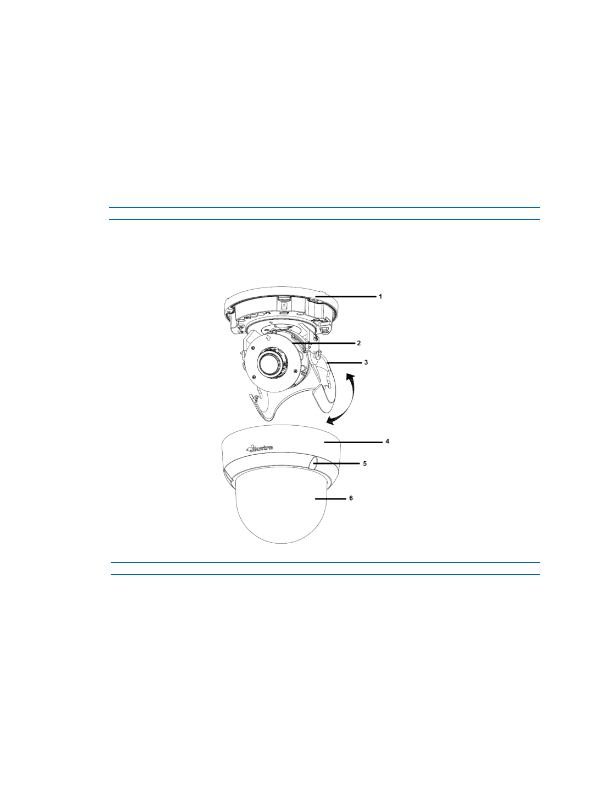
Table 6 Pictorial index descriptions
Index number Description
1 Camera bottom case
2 Tilt adjustment bracket
3 Loosen the screw to take off camera housing
4 Camera housing
5 Dome cover
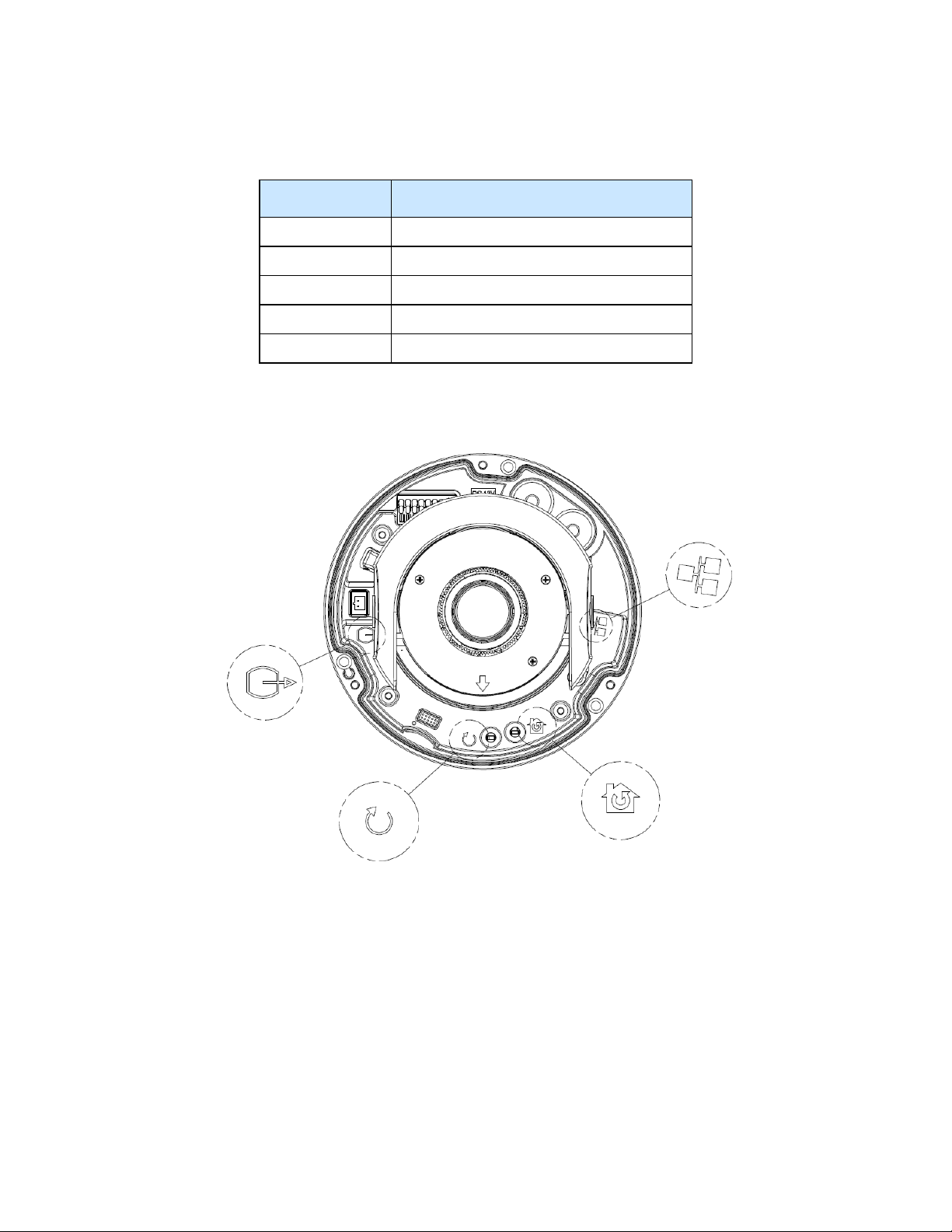
Figure 7 Pin definitions of the unit
11 8200-1456-01 J0
Page 12
Illustra Flex Series Installation and Configuration Guide
Table 8 Interior button descriptions
Interior button Description
Resets to factory default by pressing and holding the button for five seconds.
Reboots the unit.
Analog out port.
Power over Ethernet (PoE) port.
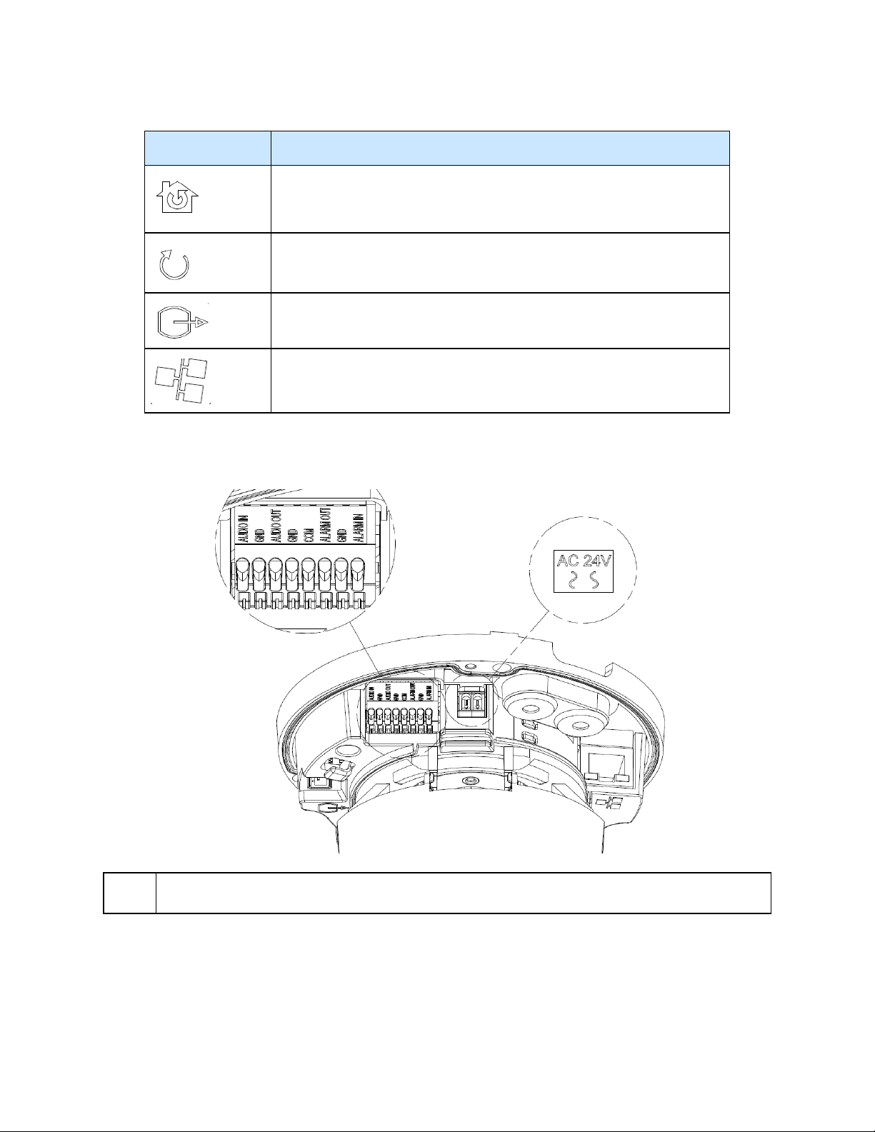
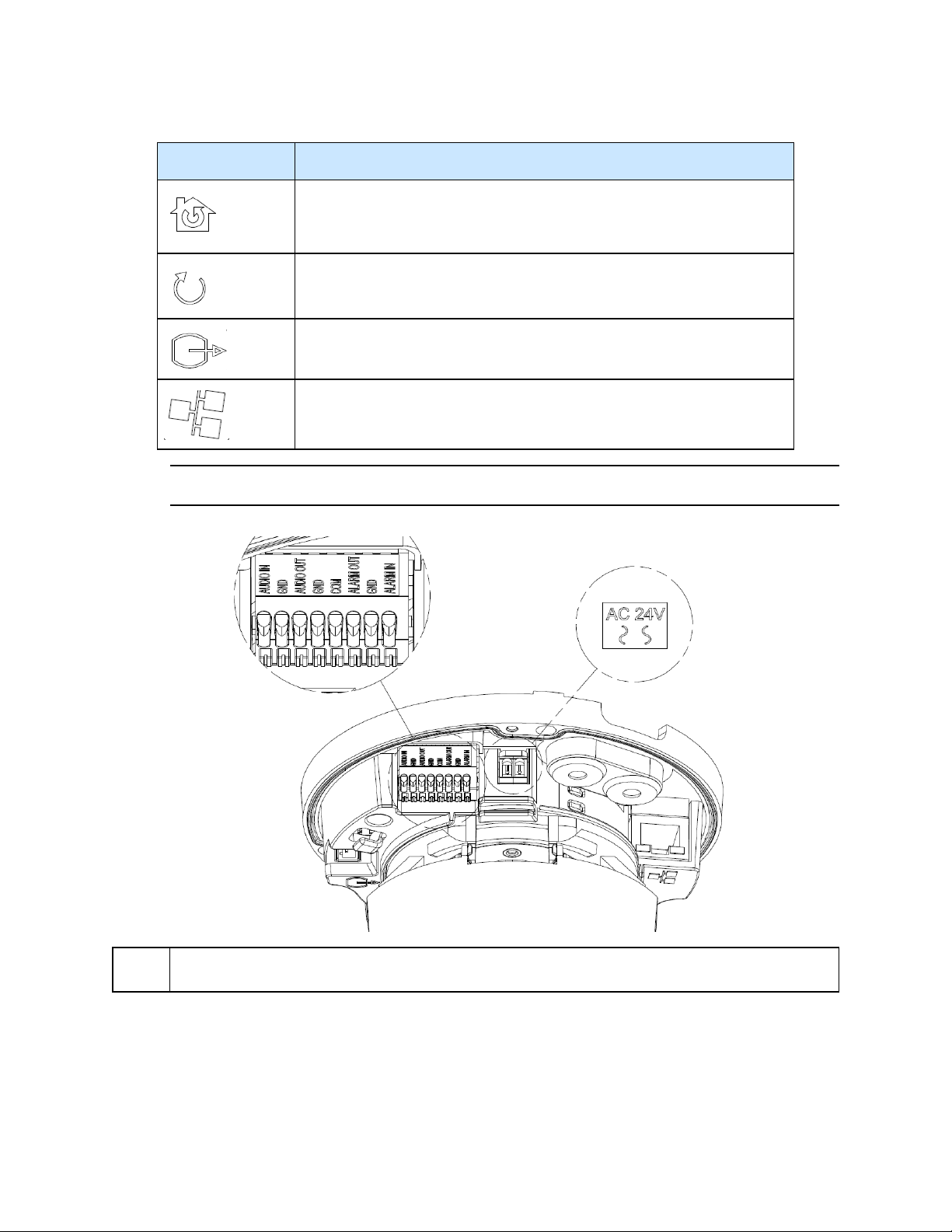
Figure 9 Connectors of the camera
NOTE
Connectors and field wiring terminals for external Class 2 circuits provided with marking indicating
minimum Class of wiring to be used. Class 2 shall be marked adjacent to the field wiring terminals.
8200-1456-01 J0 12
Page 13
Installation
In the box
Illustra Flex Series Installation and Configuration Guide
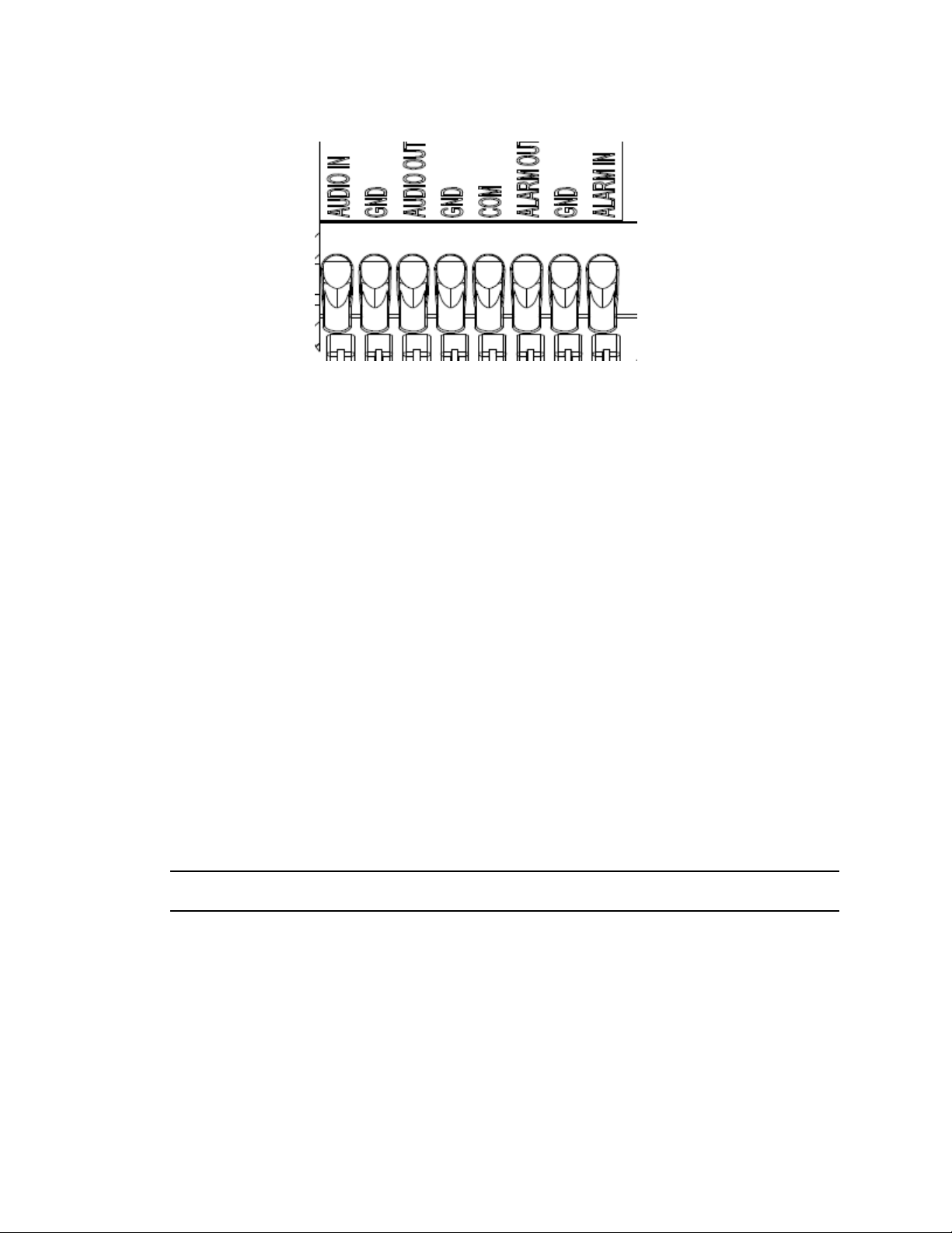
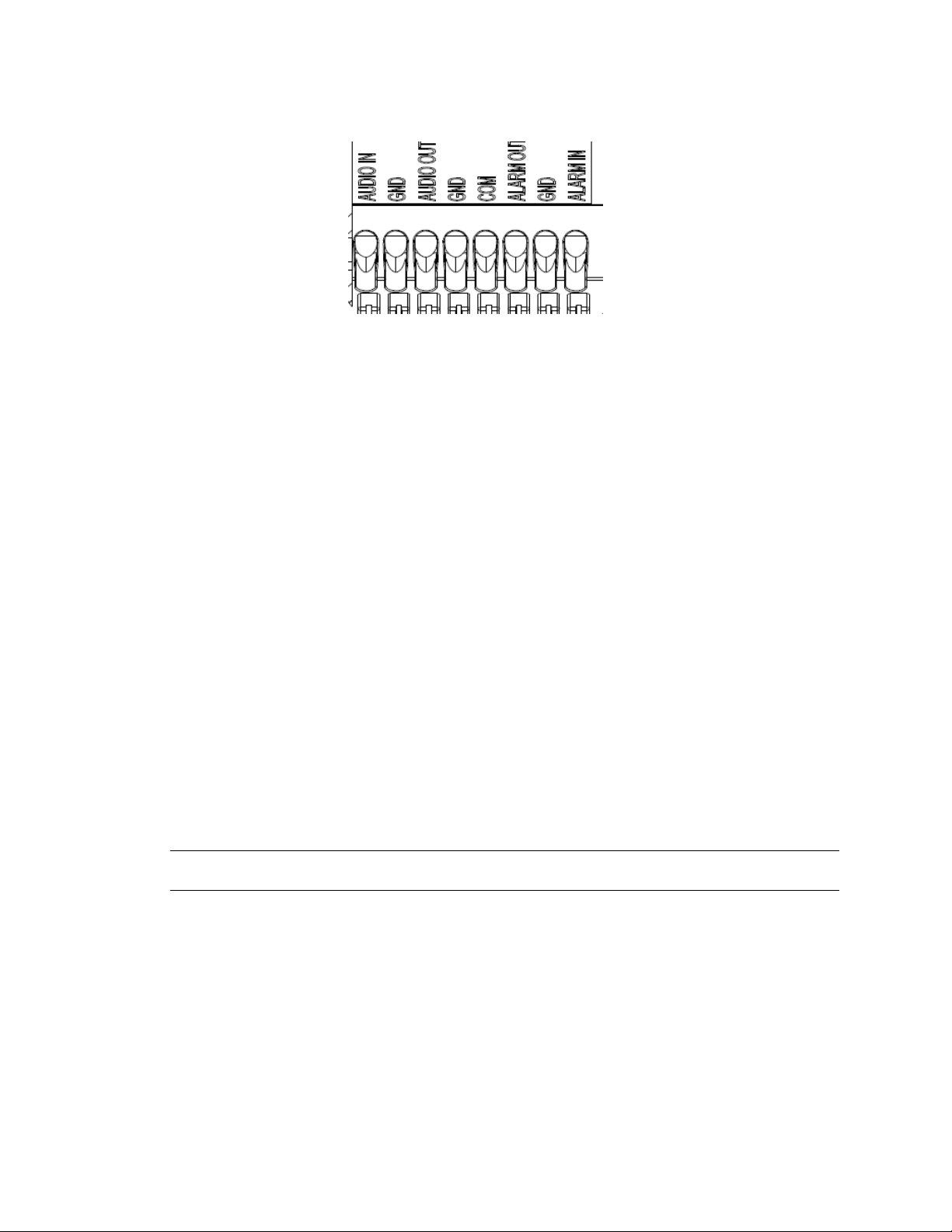
Figure 10 Audio and alarm pin definitions
Check everything in the packing box matches to the order form and the packing slip. In addition to
this guide, items below are included in the packing box:
• 1 Network Illustra Flex Indoor Dome Camera
• 1 printed Quick Start Guide
• 1 printed Regulatory document
• 1 NTSC/PAL output female BNC cable
• 1 adapter plate (for pendant cap
• 3 7mm adapter plate screws
• 1 Torx 10 Security L-Key
• 3 18mm plastic anchors and screws
• 1 installation template sticker
• 2 8mm pendant cap screws
Contact your dealer if any item is missing.
Note:The adapter plate is for an installation with a ADCi6DPCAPI (W/B) pendant cap and can also
be used to mount to a standard dual gang electrical box.
Installation tools
The following tools assist with installation:
• a drill
• screwdrivers
• wire cutters
13 8200-1456-01 J0
Page 14
Illustra Flex Series Installation and Configuration Guide
Checking appearance
When first unboxing, check whether if there is any visible damage to the appearance of the unit and
its accessories. The protective materials used for the packaging should be able to protect the unit
from most types of accidents during transportation.
Remove the protective part of the unit when every item is checked in accordance with the list in In
the box on page 13.
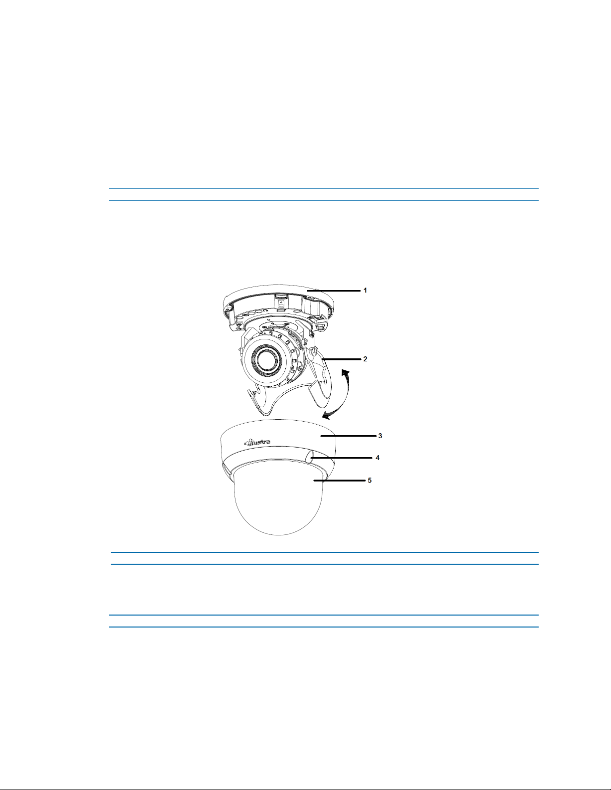
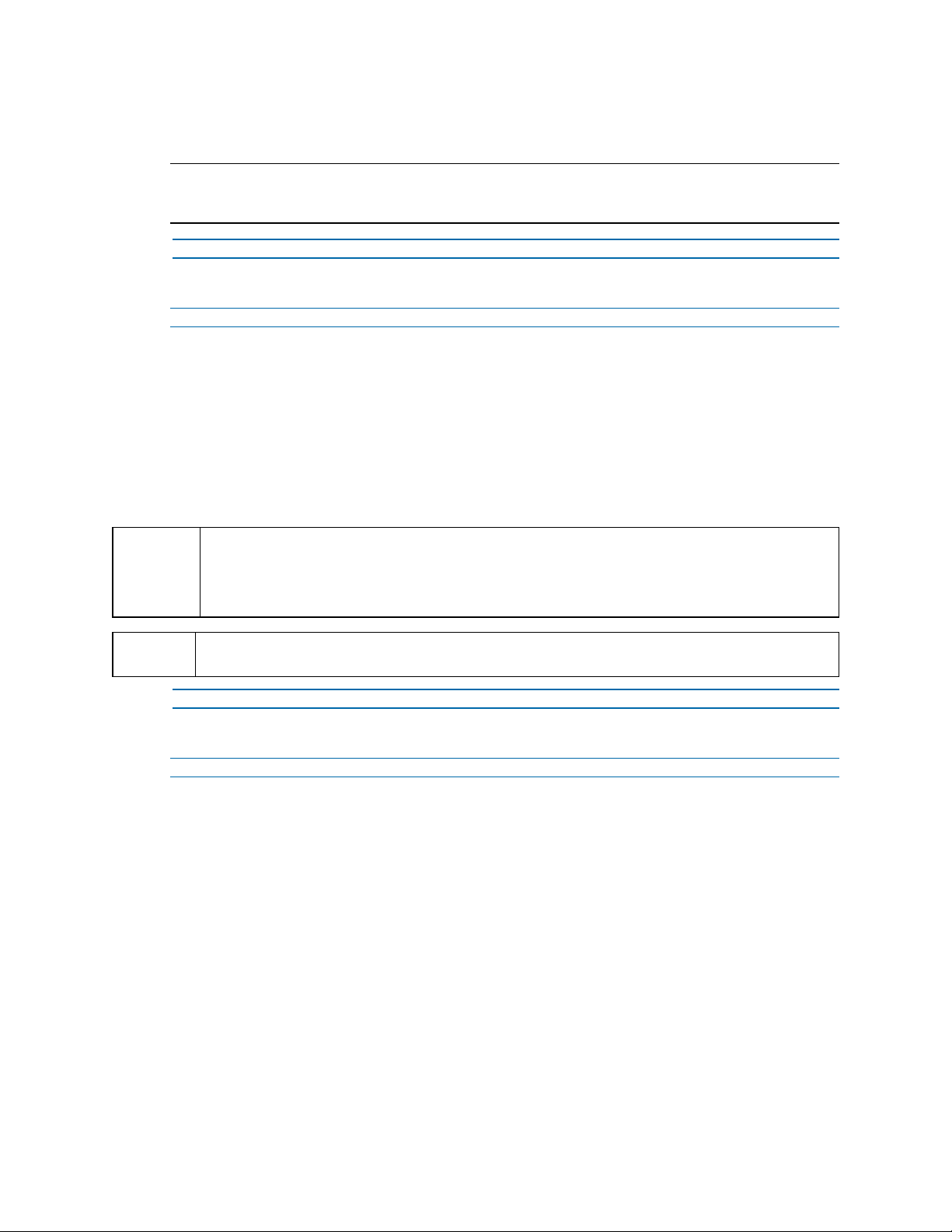
Procedure 1 Disassembling the camera
Refer to Figure 11 on page 14 for a pictorial index of disassembling the camera.
Step Action
1 Remove the screws (5) to take off camera housing.
2 Gently remove the camera housing (4) and dome cover (6) and set aside.
Figure 11 Disassembling the camera
- End -
Procedure 2 Connecting the wires
Step Action
This unit supports one of the following options as power supply:
1 AC 24V:
a Connect 24V (~ ) cables to terminals ~ AC 24V
2 PoE:
8200-1456-01 J0 14
Page 15
Illustra Flex Series Installation and Configuration Guide
a Connect the RJ-45 jack to a PoE compatible network device that supplied power
through the Ethernet cable.
3 Insert Audio cable and alarm cable to the unit, and connect the network cable to the RJ-45
terminal of a switch.
Note:The power source needs to be NEC Class 2 or LPS. The PoE connection should be provided
by a UL Listed product and the connections shall be made in accordance with Article 800 of the NEC
or local regulations.
- End -
Procedure 3 Mounting the camera
Step Action
1 Mark holes that correspond to the camera base on the mounting surface
2 Drill holes.
3 Fasten the anchors to the mounting surface with screws.
4 Connect the Safety Wire (fall prevention wire, not supplied) with one end to the ceiling and
the other to the safety-cord screw of the unit.
5 Secure the unit bottom case to the wall or ceiling with tapping screws.
6 Adjust the viewing angle. Refer to Adjusting the Position on page 15 for information
WARNING
CAUTION
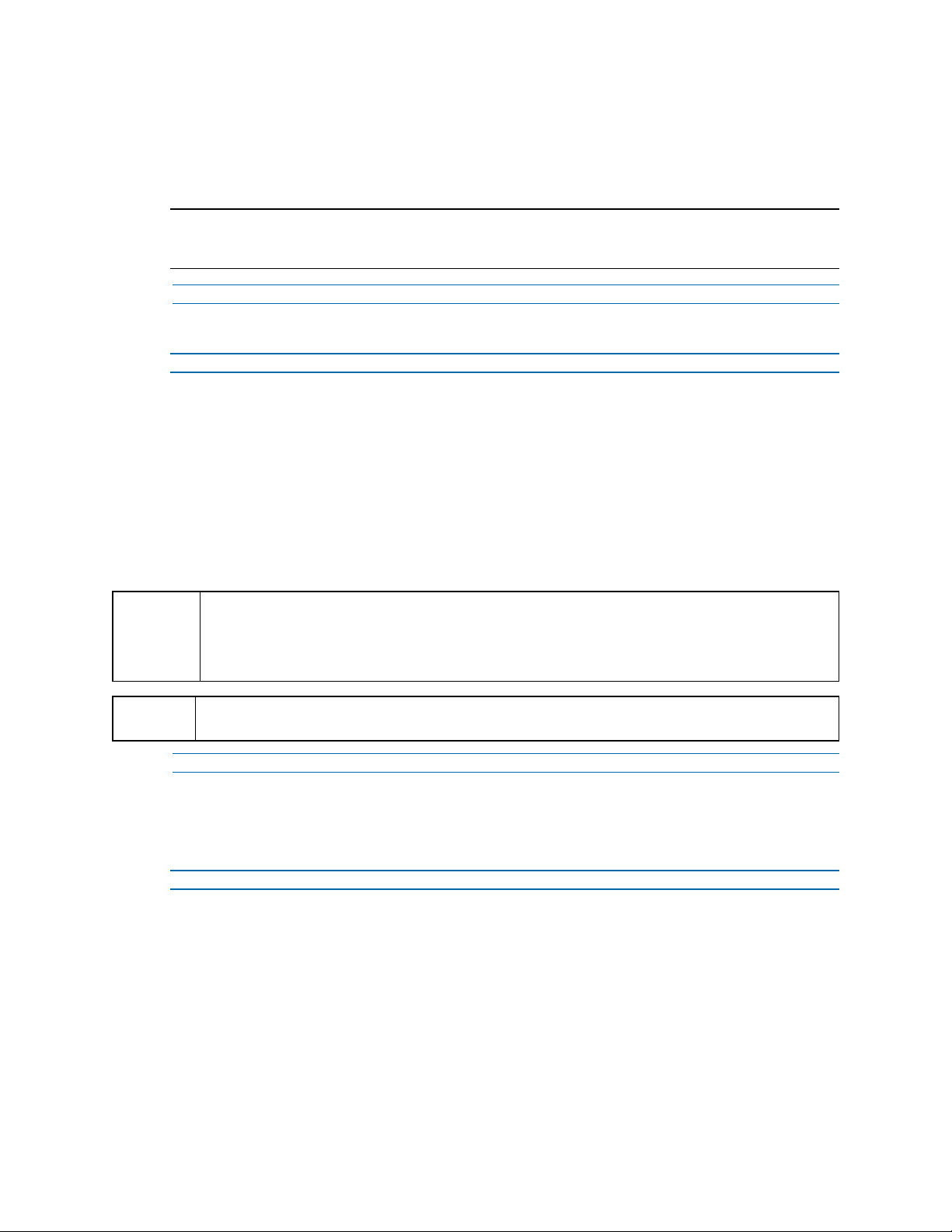
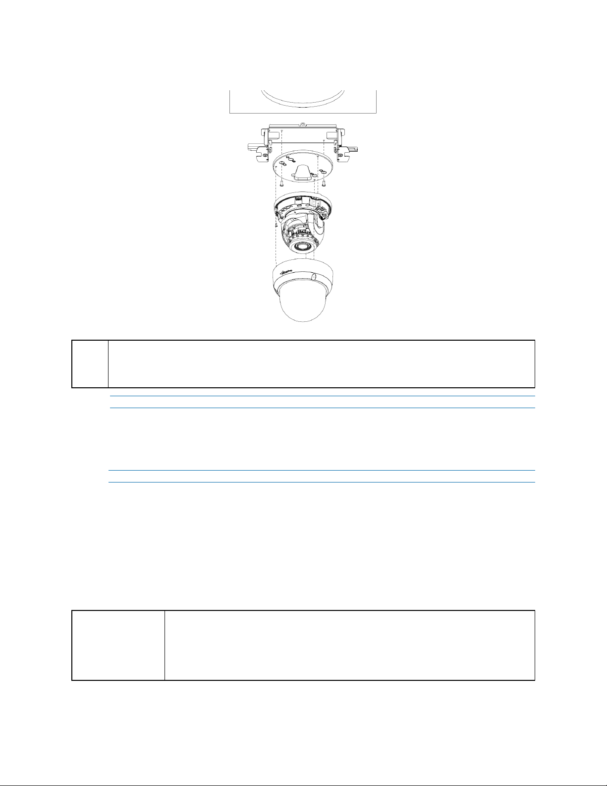
Procedure 4 Adjusting the Position
The unit has three axes for positioning, refer to Figure 12 on page 16. While monitoring, adjust the
position as below:
Step Action
1 Pan Adjustment (A). For Wall Mount and Tilted Ceilings
2 Horizontal Rotation (B)
regarding how to adjust the viewing angle.
Depending on the material of your mounting surface, you may require different screws and
anchors than those as supplied. To prevent the unit from falling off, ensure that it is secured to a
firm place (ceiling slab or channel) with a safety wire (not supplied) strong enough to sustain the
total weight of the unit. Pay attention to the finishing at the end of the wire. Never turn the lens
more than 360°, which should disconnect or break internal cables.
Safety wire must be connected with one end to the ceiling and the other to the safety-cord screw of
the unit.
- End -
a Rotate the lens base (maximum 375°) until you are satisfied with the field of view.
a Rotate 3D assembly in the base. Do not turn assembly more than 360° as this
assembly may cause the internal cables to twist and disconnect or break.
3 Tilt Adjustment (C):
a Tilt the lens base (maximum 90°) until you are satisfied with the field of view.
15 8200-1456-01 J0
Page 16
Illustra Flex Series Installation and Configuration Guide
Limitation for three axes position:
CAUTION
• Pan range: 375°
• Tilt range: 90°
• Rotate range: Motorize Lens 356°
Figure 12 Adjusting the position of the camera
- End -
Procedure 5 Locking the Camera
Step Action
1 Use a soft, lint-free cloth to wipe the dome cover and remove fingerprints.
2 Attach the inner liner and camera housing.
3 Turn the power on after you have install the unit.
- End -
8200-1456-01 J0 16
Page 17
Illustra Flex Series Installation and Configuration Guide
Illustra Flex Series 3MP and 8MP Outdoor Dome
Camera
This chapter provides product features, installation procedures, and connection information regarding
the Illustra Flex Series Outdoor Dome cameras.
Product features
Len cases require special care when handling and cleaning to avoid scratches. For information on
bubble handling and cleaning, see 8200-1174-01 Bubble Clearing Procedure Application Note.
Go to https://illustracameras.com/products.
From the Products page, select your camera product range and then select your camera model. Click
Downloads and search for Bubble Handling and Cleaning Procedure.
Product overview
This chapter explains the features and installation of the Illustra Flex Outdoor Dome camera. Product
code and description of the camera is provided in the table below.
Product
Code
IFS03D1OCWIT
IFS08D2OCWIT
Figure 14 Physical dimensions of the Illustra Flex Outdoor Dome camera (mm)
Table 13 Product code and description of the Illustra Flex Outdoor camera
Model Name Description
Illustra Flex 3MP Outdoor
Mini-Dome
Illustra Flex 4K Outdoor
Mini-Dome
Illustra Flex 3MP Mini-dome, 2.8-12mm, outdoor, vandal, clear,
white, TDN w/IR, TWDR
Illustra Flex 8MP Mini-dome, 3.4-9mm, outdoor, vandal, clear,
white, TDN w/IR, TWDR
17 8200-1456-01 J0
Page 18
Illustra Flex Series Installation and Configuration Guide
Figure 15 Physical dimensions of the Illustra Flex Outdoor Dome camera
Figure 16 Pictorial index of the Illustra Flex Outdoor Dome camera
8200-1456-01 J0 18
Page 19
Illustra Flex Series Installation and Configuration Guide
Table 17 Pictorial index descriptions
Index number Description
1 Camera bottom case
2 IR board
3 Tilt adjustment bracket
4 Camera top case
5 Loosen the screw to take off camera housing
6 Dome cover
Figure 18 Pin definitions of the unit
19 8200-1456-01 J0
Page 20
Illustra Flex Series Installation and Configuration Guide
Table 19 Interior button descriptions
Interior button Description
Resets to factory default by pressing and holding the button for five seconds.
Reboots the unit.
Analog out port.
Power over Ethernet (PoE) port.
Note:The connector cable of the Outdoor Dome Camera should be contained in a conduit suitable for
outdoor use.
NOTE
Figure 20 Connectors of the unit
Connectors and field wiring terminals for external Class 2 circuits provided with marking indicating
minimum Class of wiring to be used. Class 2 shall be marked adjacent to the field wiring terminals.
8200-1456-01 J0 20
Page 21
Installation
In the box
Check everything in the packing box matches to the order form and the packing slip. In addition to
this guide, items below are included in the packing box.
Illustra Flex Series Installation and Configuration Guide
Figure 21 Audio and alarm pin definitions
• 1 Network Illustra Flex Outdoor Dome Camera
• 1 printed Quick Start Guide
• 1 printed Regulatory document
• 1 NTSC/PAL output female BNC cable
• 1 adapter plate (for pendant cap)
• 3 7mm adapter plate screws
• Desiccant
• 1 Torx 10 Security L-Key
• 3 18mm plastic anchors and screws
• 1 installation template sticker
• 2 8mm pendant cap screws
Contact your dealer if any item is missing.
Note:The adapter plate is for an installation with a ADCi6DPCAPI (W/B) pendant cap and can also
be used to mount to a standard dual gang electrical box.
Installation tools
The following tools assist with installation:
• a drill
• screwdrivers
• wire cutters
21 8200-1456-01 J0
Page 22
Illustra Flex Series Installation and Configuration Guide
Checking appearance
When first unboxing, check whether if there is any visible damage to the appearance of the unit and
its accessories. The protective materials used for the packaging should be able to protect the unit
from most types of accidents during transportation.
Remove the protective part of the unit when every item is checked in accordance with the list in In
the box on page 21.
Procedure 6 Disassembling the Camera
Step Action
1 Remove the screws (4).
2 Gently remove the camera housing (3) and dome cover (5).
3 Set the camera housing aside.
Figure 22 Disassembling the outdoor camera
- End -
Procedure 7 Connecting the wires
Connect the power cable to the power plugs with one of the following options:
Step Action
1 AC 24V:
a Insert the power cable for AC 24V.
b Connect 24 V (~) cables to terminals ~AC 24V.
2 PoE:
8200-1456-01 J0 22
Page 23
Illustra Flex Series Installation and Configuration Guide
a Connect the RJ-45 jack to a PoE compatible network device that supplies power
through the Ethernet cable.
Note:The power source needs to be NEC Class 2 or LPS. The PoE connection should be provided
by a UL Listed product and the connections shall be made in accordance with Article 800 of the NEC
or local regulations.
- End -
Procedure 8 Mounting the camera
Step Action
1 Mark holes that correspond to the camera base on the mounting surface
2 Drill holes.
3 Fasten the anchors to the mounting surface with screws.
4 Connect the Safety Wire (fall prevention wire, not supplied) with one end to the ceiling and
the other to the safety-cord screw of the unit.
5 Secure the unit bottom case to the wall or ceiling with tapping screws.
6 Adjust the viewing angle.
WARNING
CAUTION
Procedure 9 Optional - 4S Electrical Junction Box
Step Action
1 Secure the mounting kit (optional) to 4S Electrical box using 2 appropriate screws.
2 Secure the unit case to mounting kit using 2 appropriate screws.
3 Tuck the cables in the 4S Electrical box.
4 Adjust the view angles.
5 Attach the unit housing.
6 Turn the power on after you install the unit.
Depending on the material of your mounting surface, you may require different screws and
anchors than those as supplied. To prevent the unit from falling off, ensure that it is secured to a
firm place (ceiling slab or channel) with a safety wire (not supplied) strong enough to sustain the
total weight of the unit. Pay also attention to the finishing at the end of the wire. Never turn the lens
more than 360°, which should disconnect or break internal cables.
Safety wire must be connected with one end to the ceiling and the other to the safety-cord screw of
the unit.
- End -
23 8200-1456-01 J0
Page 24
Illustra Flex Series Installation and Configuration Guide
Figure 23 Mounting the camera with the junction box
NOTE
Procedure 10 Adjusting the Position
The unit has three axes for positioning, refer to Figure 24 on page 25. While monitoring, adjust the
position as below.
Step Action
CAUTION
The mounting kit called out in Figure 23 on page 24 is not supplied with the unit.
Keeping tilt angle over 25 degrees is recommended when IR-LED light is used. If tilt angel is below 25
degrees from the horizontal, the image would be flashed by the reflection of IR-LED light.
- End -
1 Pan Adjustment (A) For Wall Mount and Tilted Ceilings:
a Rotate the lens base (maximum 375°) until you are satisfied with the field of view.
2 Horizontal Rotation (B):
a Rotate 3D assembly in the base. Do not turn assembly more than 360° as this
assembly may cause the internal cables to twist and disconnect or break.
3 Tilt Adjustment (C):
a Tilt the lens base (maximum 90°) until you are satisfied with the field of view.
Limitation for three axes position:
• Pan range: 375°
• Tilt range: 75°
• Rotate range: Motorize Lens 356°
8200-1456-01 J0 24
Page 25
Illustra Flex Series Installation and Configuration Guide
Figure 24 Adjusting the position of the camera
NOTE
For outdoor Dome camera series:
Users can adjust zoom level and focus level using the Illustra Connect Web User
Interface.
- End -
Procedure 11 Locking the Camera
Step Action
1 Use a soft, lint-free cloth to wipe the dome cover and remove fingerprints.
2 Attach the inner liner and camera housing.
3 Turn the power on after you have install the unit.
- End -
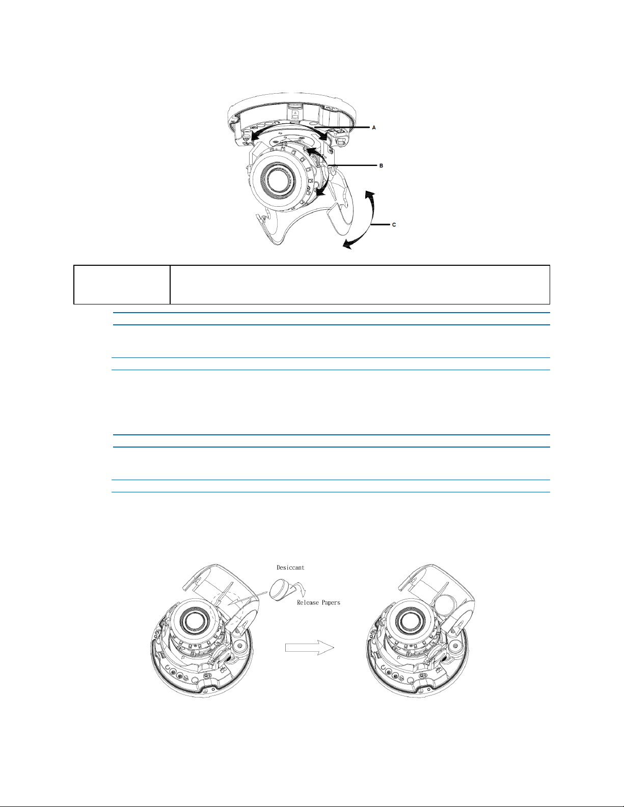
Procedure 12 Applying the desiccant
Step Action
1 Remove the papers from the back of the desiccant.
2 Attach to the interior side of the tilt adjuster as seen in the image below.
Figure 25 Location for desiccant application
25 8200-1456-01 J0
Page 26
Illustra Flex Series Installation and Configuration Guide
Illustra Flex Series 3MP and 8MP Outdoor Bullet
Cameras
Product features
Len cases require special care when handling and cleaning to avoid scratches. For information on
bubble handling and cleaning, see 8200-1174-01 Bubble Clearing Procedure Application Note.
Go to https://illustracameras.com/products.
From the Products page, select your camera product range and then select your camera model. Click
Downloads and search for Bubble Handling and Cleaning Procedure.
Product overview
This chapter explains the features and installation of the Illustra Flex Bullet cameras. Product code
and description of the camera is provided in the table below.
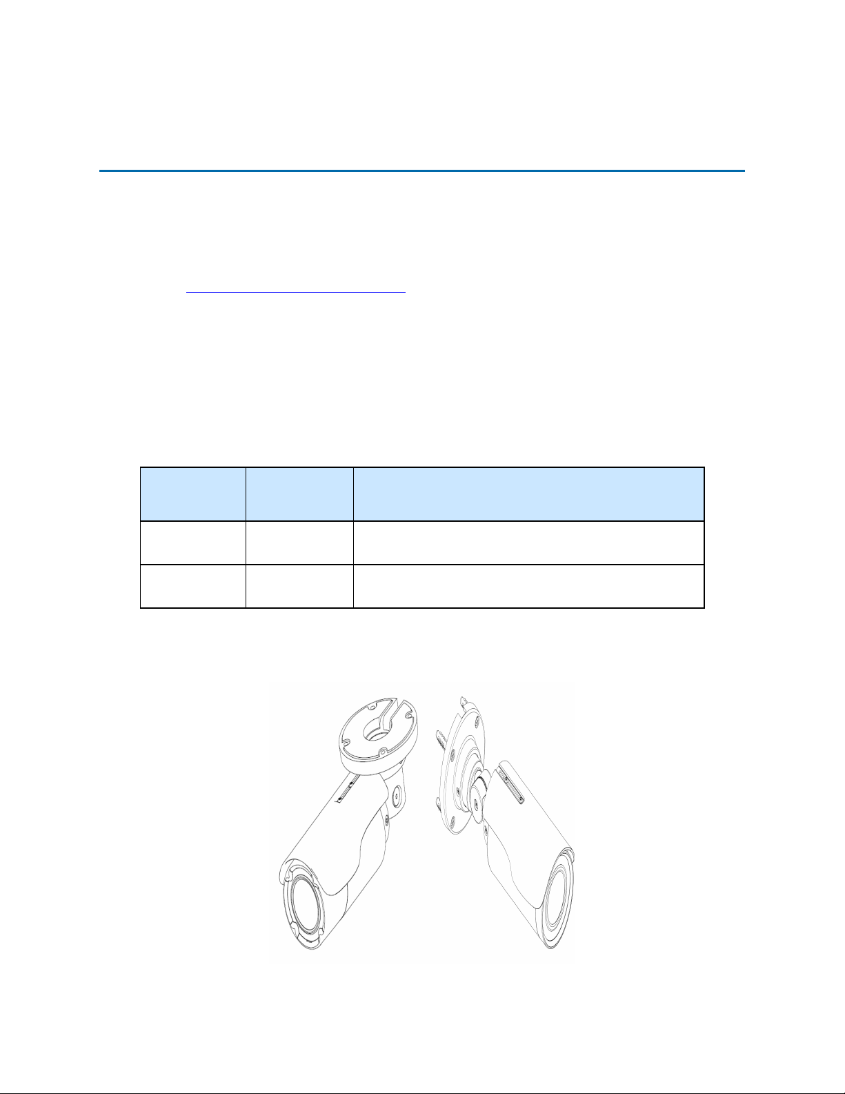
Table 26 Product code and description of the Illustra Flex Bullet cameras
Product
Code
IFS03B1BNWIT
IFS08B2ONWIT
Model Name Description
Illustra Flex
3MP bullet
Illustra Flex 4K
bullet
Figure 27 Illustra Flex 3MP and 8MP Bullet Cameras
Illustra Flex 3MP Bullet, 2.8-12mm, outdoor, non-vandal,
white, TDN w/IR, TWDR
Illustra Flex 8MP Bullet, 3.4-9mm, outdoor, non-vandal,
white, TDN w/IR, TWDR
26 8200-1456-01 J0
Page 27
Illustra Flex Series Installation and Configuration Guide
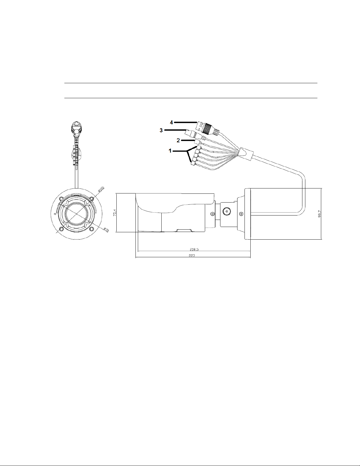
Figure 28 on page 27 and Figure 29 on page 28 illustrates dimensions and physical properties of the
units as well as a pictorial index of the camera connectors. Descriptions of these connectors are
available in Table 30 on Page 28.
Note:The connector cable of the Outdoor Bullet Camera should be contained in a conduit suitable for
outdoor use.
Figure 28 3MP Camera dimensions (mm) and pictorial index
8200-1456-01 J0 27
Page 28
Illustra Flex Series Installation and Configuration Guide
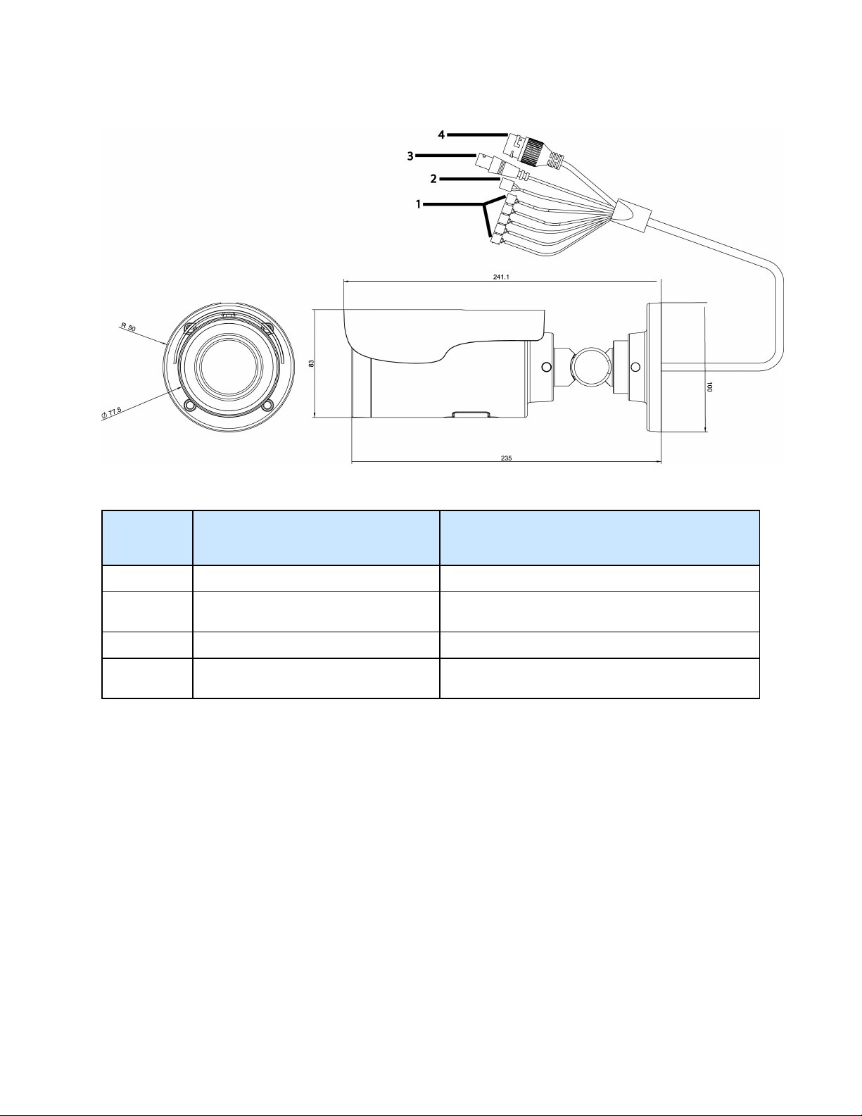
Figure 29 8MP Camera dimensions (mm) and pictorial index
Table 30 Pictorial index descriptions
Index
number
1 I/O connectors Connection for Input/Output devices.
2 Power Connector
3 BNC cable Connection for a BNC cable for analog out.
4
RJ-45 Ethernet Connector/Power over
Ethernet (PoE)
Name Description
Connection to the external power source at AC 24V
only.
Connection for the RJ-45 cable for network
connection as well as PoE.
The input and output cables of the Illustra Flex Bullet cameras are labeled with icons that designate
their usage. Input/Output connector descriptions on page 29 illustrates and describes these icons.
28 8200-1456-01 J0
Page 29
Illustra Flex Series Installation and Configuration Guide
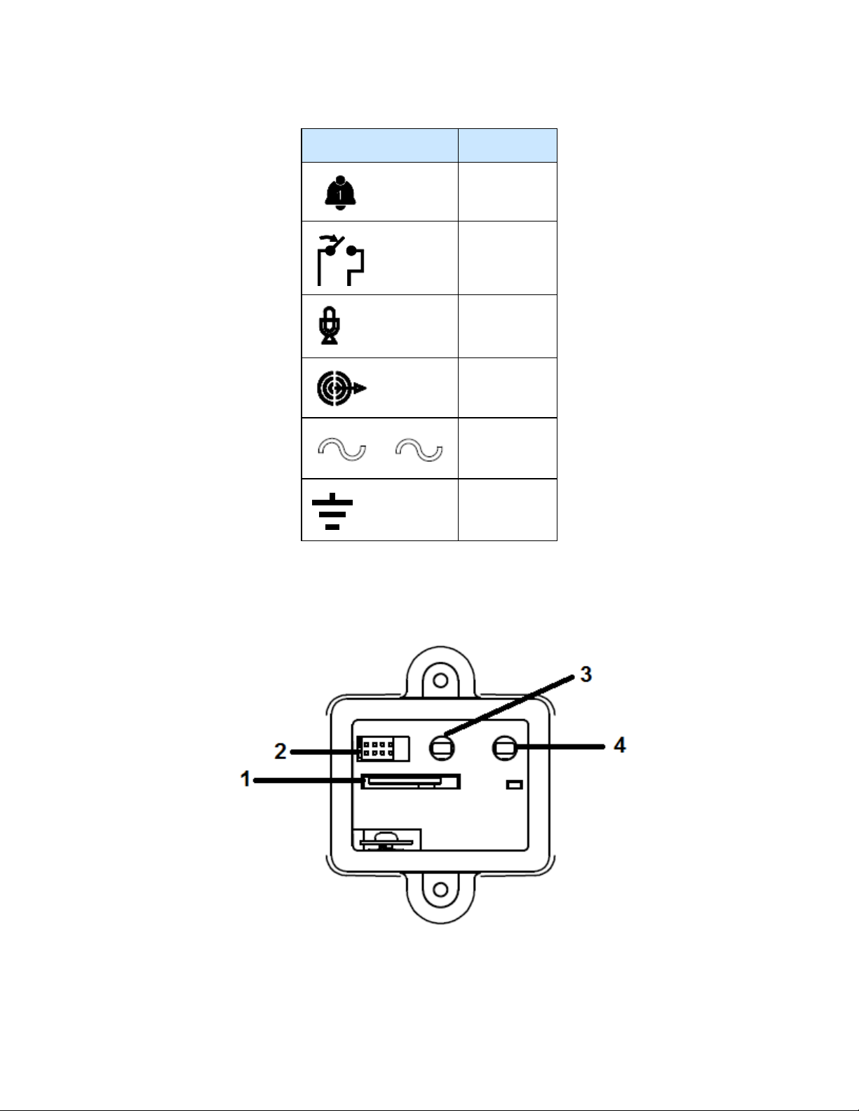
Table 31 Input/Output connector descriptions
Icon Description
Alarm In
Alarm Out
Audio In
Audio Out
Power
Ground
You can find the interior buttons and ports on the base of the Illustra Flex Bullet camera. Remove the
two screws to open the cover for access to these pins. Refer to Figure 32 on page 29 and Table 33 on
Page 30 for descriptions of these buttons and ports.
Figure 32 Interior buttons and ports of the Illustra Flex Bullet cameras
8200-1456-01 J0 29
Page 30
Illustra Flex Series Installation and Configuration Guide
Table 33 Descriptions of the interior buttons and ports of the Illustra Flex Bullet camera
Index number Name
1 Micro SD card slot
2 Serial port
3 Default: returns to factory default by pressing the button for five seconds
4 Reset: system restart
CAUTION
NOTE
When removing the screws for the default/reset cover, ensure you replace and tighten the
screws to avoid water leaking after adjustment.
Connectors and field wiring terminals for external Class 2 circuits provided with marking
indicating minimum Class of wiring should be used. Class 2 should be marked adjacent to the
field wiring terminals.
Installation
In the box
Check everything in the packing box matches to the order form and the packing slip. In addition to
this guide, items below are included in the packing box:
• 1 Network Illustra Flex IR Bullet Camera
• 1 printed Quick Start Guide
• 1 printed Regulatory document
• 4 31mm screws and anchors
• 1 installation template sticker
• 1 Torx 10 and 20 Security L-Key (3MP Bullet camera)
• 1 T10-T10 Security L-Key (8MP Bullet camera)
Contact your dealer if any item is missing.
Installation tools
The following tools assist with installation:
• a drill
• screwdrivers
• wire cutters
Checking appearance
When first unboxing, check whether if there is any visible damage to the appearance of the unit and
its accessories. The protective materials used for the packaging should be able to protect the unit
from most types of accidents during transportation.
30 8200-1456-01 J0
Page 31

Illustra Flex Series Installation and Configuration Guide
Remove the protective part of the unit when every item is checked in accordance with the list in In
the box on page 30.
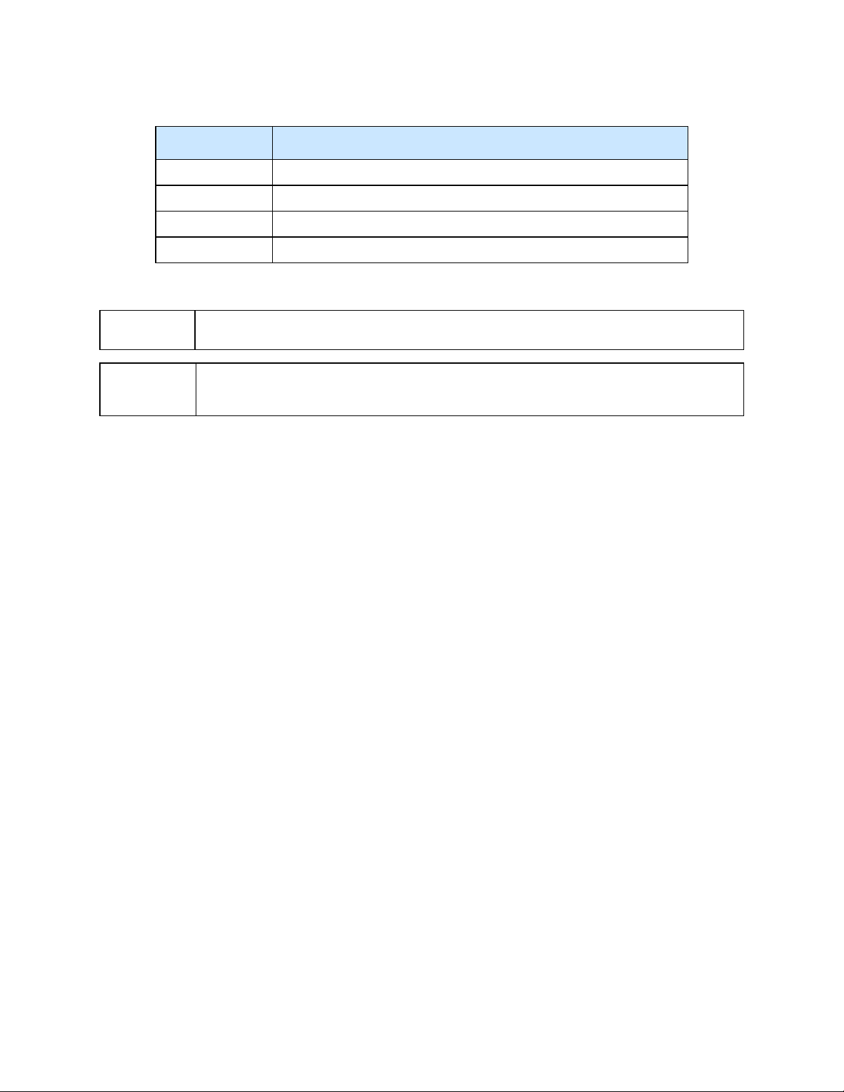
Procedure 13 Mounting the camera
Step Action
1 Affix the mounting template to the surface. After you drill the holes, knock in 4 plastic
anchors and then lock in the 4 self-tapping screws to fasten the camera to the surface.
Figure 34 Mounting the Illustra Flex 3MP Bullet camera to a ceiling
Figure 35 Mounting the Illustra Flex 8MP Bullet camera to a ceiling
2 Mount the unit onto the ceiling and fasten it securely as seen in Figure 34 on page 31 and
Figure 35 on page 31 or if mounting onto a wall refer to Figure 36 on page 32 and Figure 37 on
page 32.
8200-1456-01 J0 31
Page 32

Illustra Flex Series Installation and Configuration Guide
Figure 36 Mounting the Illustra Flex 3MP Bullet camera to a wall
Figure 37 Mounting the Illustra Flex 8MP Bullet camera to a wall
WARNING
CAUTION
Depending on the material of mounting surface, different screws and anchors than those supplied
with the product may be required. To prevent the unit from falling off the surface, ensure that it is
mounted to a firm location (ceiling slab or channel) using a safety wire strong enough to withstand
the total weight of the unit. Be aware of the finishing at the end of the wire.
Safety wire should be connected, if supplied or ordered seperately, with one end the wall or ceiling
and the other to the safety-cord screw of the unit. By cabling so, it is possible to prevent the unit
from accidental falling in a sudden at any time.
- End -
32 8200-1456-01 J0
Page 33

Illustra Flex Series Installation and Configuration Guide
Procedure 14 Connecting the wires
Step Action
1 Attach the camera to the fixed surface.
2 Pass all the signal cables through the mounting bracket.
3 Connect the power cable to the power plugs with one of the following options:
a AC 24V: Connect 24V (~) cables to terminals ~AC 24V.
b PoE: Connect the RJ-45 jack to a PoE compatible network device that supplies power
through the Ethernet cable.
4 Insert audio cable and alarm cable to the unit. Connect the network cable to the RJ-45
terminal of a switch. Refer to Input/Output connector descriptions on page 29 for further
information regarding wiring.
Note:The power source needs to be NEC Class 2 or LPS. The PoE connection should be provided
by a UL Listed product and the connections shall be made in accordance with Article 800 of the NEC
or local regulations.
- End -
Procedure 15 Adjusting the camera position
Step Action
1 Use the security key to loosen the security torx screw on one side of the mount bracket so
that you can tilt the camera.
2 Loosen the screw on the retaining ring to adjust the camera angle.
3 After adjustments, fasten the screws and retaining ring back to the camera.
Figure 38 Adjusting the 3MP camera position
8200-1456-01 J0 33
Page 34

Illustra Flex Series Installation and Configuration Guide
Figure 39 Adjusting the 8MP camera position
Procedure 16 Adjusting the sun shield hood
Step Action
1 Move the sun shield hood forward and backward to adjust the position of sunshade.
CAUTION
• Ensure to adjust the sun shield hood in coordination with lens in case of sunshade problems.
• To avoid damage to the housing of the unit, do not adjust the sun shield position excessively.
- End -
34 8200-1456-01 J0
Page 35

Illustra Flex Series Installation and Configuration Guide
Illustra Flex Series 3MP and 8MP Indoor Box
Camera
Product features
Len cases require special care when handling and cleaning to avoid scratches. For information on
bubble handling and cleaning, see 8200-1174-01 Bubble Clearing Procedure Application Note.
Go to https://illustracameras.com/products.
From the Products page, select your camera product range and then select your camera model. Click
Downloads and search for Bubble Handling and Cleaning Procedure.
Product overview
This chapter explains the features and installation of the Illustra Flex Indoor Box cameras. Product
code and description of the cameras is provided in the table below.
Table 40 Product code and description of the Illustra Flex Indoor Box cameras
Product
Code
IFS03XNANWTT
IFS08XNANWTT
Model Name Description
Illustra Flex 3MP
Box
Illustra Flex 4K
Box
Figure 41 Camera dimensions
Illustra Flex 3MP Box, no lens,
indoor, non-vandal, white, TDN,
TWDR
Illustra Flex 8MP Box, no lens,
indoor, non-vandal, white, TDN,
TWDR
35 8200-1456-01 J0
Page 36

Illustra Flex Series Installation and Configuration Guide
Camera connectors
Figure 42 on page 36 and Table 43 on Page 37 describe the connectors of the camera and their
designations.
Figure 42 Camera connectors
8200-1456-01 J0 36
Page 37

Illustra Flex Series Installation and Configuration Guide
Table 43 Connector descriptions
Index Name Description
1
2 AC/DC To use AC/DC power.
3 Video Out Connection Analog out.
4 Micro SDCard Slot To use a Micro SDcard for recording and storage.
5 Reset Button To reboot the unit.
6 Default Button
7 Auto Focus Button To apply backup focus.
8 I/O Connector To connect Input/Output devices.
RJ-45 Ethernet
Connector/PoE
To insert the RJ-45 cable for network connection as well as Power
over Ethernet (PoE)
To reset all settings of the unit to factory default, press for 5
seconds.
Figure 44 on page 37 and Table 45 on Page 37 describe the input and output connectors and icons on
the unit.
Figure 44 I/O connectors
Table 45 I/O connectors icon descriptions
Icon Description
RS-485 input and output
Alarm in
Alarm out
37 8200-1456-01 J0
Page 38

Illustra Flex Series Installation and Configuration Guide
Icon Description
Audio input
Audio output
Installation
In the box
Check everything in the box matches the order form and the packing slip. In addition to his manual,
the items below are included in the box.
• 1 network Illustra Flex Box Camera
• 1 2 position 3mm Euro style plug
• 1 printed Quick Start Guide
• 1 printed Regulatory document
Please contact your dealer if any item is missing.
Installation tools
Use the following tools to complete the installation:
• Drill
• Screwdriver
• Wire cutters
Checking appearance
When first taking the camera out of the box, check if there is any visible damage to the appearance of
the unit and its accessories. The protective materials used for the packaging should protect the unit
from most potential accidents during transportation.
Procedure 17 Connecting the wires
To connect the wires to the correct tables, complete the following steps:
Step Action
1 Connect the power cable to the power plugs with on of the following options:
a DC12V: Connect 12V(- ) to terminal = DC 12V-, and connect 12V(+ ) to terminal =DC
12V+
b AC24V: Connect 24V (~) cables to terminals ~AC 24V
c PoE: Connect the RJ-45 jack to a PoE compatible network device that supplies power
through the Ethernet cable.
2 Insert the audio cable and alarm cable to the unit, and connect the network cable to the RJ-
45 terminal of a switch.
8200-1456-01 J0 38
Page 39

Illustra Flex Series Installation and Configuration Guide
Note:The power source needs to be NEC Class 2 or LPS. The PoE connection should be provided
by a UL Listed product and the connections shall be made in accordance with Article 800 of the NEC
or local regulations.
CAUTION
Procedure 18 Mounting the camera
To mount the camera, complete the following steps:
Step Action
NOTE
If using DCsupply, make sure the polarity is correct. Incorrect connection can cause malfunction
and/or damage.
- End -
1 Attach the camera unit to a pendant mount (not supplied), and insert and tighten the screws
on the tripod receptacle into the screw holes on the base.
2 Mount the camera unit onto the ceiling or wall and fasten securely.
3 Connect the Safety Wire (Fall Prevention Wire, not supplied). One end connects to the wall
or ceiling and the other connects to the safety-cord screw of the camera unit.
Depending on the material of the mounting surface, different screws and anchors than those
supplied may be required. To prevent the unit from falling off, ensure that it is mounted to a firm
place, such as a ceiling slab or channel, using a safety wire strong enough to withstand the total
weight of the unit. Safety wire must be connected with one end the wall or ceiling and the other to the
safety cord screw of the unit. This helps prevent the unit from falling.
- End -
39 8200-1456-01 J0
Page 40

Illustra Flex Series Installation and Configuration Guide
Illustra Flex 3MP Outdoor Compact Mini Dome
Camera
This chapter provides product features, installation procedures, and connection information regarding
the Illustra Flex 3MP Outdoor Dome camera.
Product features
Lens cases require special care when handling and cleaning to avoid scratches. For information on
bubble handling and cleaning, see 8200-1174-01 Bubble Clearing Procedure Application Note.
Go to https://illustracameras.com/products.
From the Products page, select your camera product range and then select your camera model. Click
Downloads and search for Bubble Handling and Cleaning Procedure.
Product overview
This chapter explains the features and installation of the llustra Flex 3MP Compact Mini Dome
camera. Product code and description of the camera is provided in Table 46 on page 40.
Table 46 Product code and description of the Compact Mini Dome camera
Product Code Description
IFS03CFOCWST Illustra Flex 3MP Compact Dome, 2.8mm, outdoor, vandal, clear, white, SDN, TWDR
Figure 47 Physical dimensions of the Compact Mini Dome camera (mm)
8200-1456-01 J0 40
Page 41

Illustra Flex Series Installation and Configuration Guide
Figure 48 Physical dimensions of the Compact Mini Dome camera (mm)
Figure 49 Pictorial index of the Compact Mini Dome camera
41 8200-1456-01 J0
Page 42

Illustra Flex Series Installation and Configuration Guide
Table 50 Pictorial index descriptions
Index number Description
1 Camera base
2 Lens Unit
3 Camera top case
4
5 Dome cover
Screw casing (Loosen the screws to take off
the top cover)
Figure 51 Interior view and buttons of the unit
8200-1456-01 J0 42
Page 43

Interior button Description
Note:The connector cable of the Compact Mini Dome camera should be contained in a conduit
suitable for outdoor use
Note:Connectors and field wiring terminals for external Class 2 circuits provided with marking
indicating minimum Class of wiring to be used. Class 2 shall be marked adjacent to the field wiring
terminals.
Installation
Illustra Flex Series Installation and Configuration Guide
Table 52 Interior button descriptions
Resets to factory default by pressing and holding the button for five seconds.
Reboots the unit.
In the box
Check everything in the packing box matches to the order form and the packing slip. In addition to
this guide, items below are included in the packing box.
• 2 Plastic Anchors and screws 35mm
• 1 T20 Security Torx Wrench
• 1 Installation template sticker
• 1 printed Quick Start Guide
• 1 printed Regulatory document
• 1 Desiccant bag
Contact your dealer if any item is missing.
Installation tools
The following tools assist with installation:
• a drill
• screwdrivers
• wire cutters
Checking appearance
When first unboxing, check whether if there is any visible damage to the appearance of the unit and
its accessories. The protective materials used for the packaging should be able to protect the unit
from most types of accidents during transportation. Remove the protective part of the unit when
every item is checked in accordance with the list in In the box on page 43.
43 8200-1456-01 J0
Page 44

Illustra Flex Series Installation and Configuration Guide
Procedure 19 Disassembling the Camera
Step Action
1 Remove the bungs from the camera base and remove the screws from the top of the camera
with a safety screwdriver (4).
2 Gently remove the top cover (3).
3 Set the top cover aside.
Note:Unscrew the top cover safety wire to fully remove the top cover.
Figure 53 Disassembling the Compact Mini Dome camera
- End -
Procedure 20 Mounting the camera
Step Action
1 Use the mounting template to mark holes that correspond to the camera base on the mount-
ing surface.
2 Drill holes.
3 Fasten the anchors to the mounting surface with screws.
4 Secure the unit bottom case to the wall or ceiling with tapping screws.
5 Adjust the viewing angle.
8200-1456-01 J0 44
Page 45

Illustra Flex Series Installation and Configuration Guide
6 Ensure that the top cover safety wire is connected and securely fit the top cover.
Figure 54 Mounting the camera
WARNING
CAUTION
Depending on the material of your mounting surface, you may require different screws and
anchors than those as supplied. To prevent the unit from falling off, ensure that it is secured to a
firm place (ceiling slab or channel) with the safety wire (supplied) strong enough to sustain the
total weight of the unit. Pay also attention to the finishing at the end of the wire. Never turn the lens
more than 360°, which should disconnect or break internal cables.
Ensure that the Safety wire is connected with one end to the ceiling and the other to the safety-cord
screw of the unit.
- End -
45 8200-1456-01 J0
Page 46

Illustra Flex Series Installation and Configuration Guide
Procedure 21 Adjusting the Position
The unit has three axes for positioning, refer to Figure 55 on page 46. While monitoring, adjust the
position as below.
Step Action
1 Pan Adjustment (A) For Wall Mount and Tilted Ceilings:
a Rotate the lens base (maximum 140°) until you are satisfied with the field of view.
2 Horizontal Rotation (B):
a Rotate 3D assembly in the base. Do not turn assembly more than 354° as this
assembly may cause the internal cables to twist and disconnect or break.
3 Tilt Adjustment (C):
a Tilt the lens base (maximum 125° from the frontal mounting surface) until you are sat-
isfied with the field of view.
Limitation of three axis positions of lens centroid:
CAUTION
• Pan range: 140°
• Tilt range: 15° to 125° from frontal mounting surface
• Rotate (z-axis): 354°
Figure 55 Adjusting the position of the camera
8200-1456-01 J0 46
Page 47

Illustra Flex Series Installation and Configuration Guide
Figure 56 Adjusting the position of the camera
NOTE
For Compact Mini Dome camera series:
The zoom level and focus are manually set in the factory.
- End -
Procedure 22 Installing the desiccant
Step Action
1 Remove the papers from the back of the desiccant.
2 Attach to the interior side of the camera cover as seen in the image below.
Figure 57 Location for desiccant application
47 8200-1456-01 J0
Page 48

Illustra Flex Series Installation and Configuration Guide
- End -
Procedure 23 Locking the Camera
Step Action
1 Use a soft, lint-free cloth to wipe the dome cover and remove fingerprints.
2 Ensure that the top cover safety wire is connected and attach the inner liner and top cover.
- End -
Procedure 24 Powering up the camera
Step Action
Connect the power cable to the power plugs as followings:
1 PoE: Connect the RJ-45 jack to a PoE compatible network device that supplies power
through the Ethernet cable.
Note:The PoE connection should be provided by a UL Listed product and the connections shall be
made in accordance with Article 800 of the NEC or local regulations.
- End -
8200-1456-01 J0 48
Page 49

Illustra Flex Series Installation and Configuration Guide
System requirements
The table below lists the minimum requirement to implement and operate the following Illustra Flex
cameras: Indoor and Outdoor Dome, Bullet, Box and Compact.
Table 58 System Requirements
System
Browser Microsoft Internet Explorer 9 or above, Firefox, Safari, Chrome
Unit
Power Supply
AC 24V / PoE
NOTE: The Box camera also supports DC 12V.
NOTE: The Compact Mini Dome camera supports PoE.
Networking
Wired
10/100BASE-T Ethernet (RJ-45 connector)
NOTE: A switch is required for surveillance on multiple units
Compact Mini Dome System Hardware
CPU Intel Pentium 4 2.4 GHz or equivalent
RAM 1 GB or above
Display NVIDIA GeForce 6 Series or ATI Mobility Radeon 9500
NOTE
CAUTION
All the installation and operations should comply with your local electricity safety rules.
To avoid damage to the unit, never connect more than one type of power supply (PoE
IEEE802.3 Ethernet Class 0 or AC24V power plug and PoE IEEE802.3 Ethernet Class 2 for the
Compact Mini Dome) at the same time. If using PoE, this camera is to be connecting only to
PoE networks without routing to heterogeneous devices.
49 8200-1456-01 J0
Page 50

Illustra Flex Series Installation and Configuration Guide
Network Topology
The Illustra Flex cameras deliver video images and audio in real-time using the internet and intranet.
It is equipped with an Ethernet RJ-45 network interface.
The following images illustra the network topologies of the cameras.
Indoor and Outdoor Dome Camera Topology
Figure 59 Dome Cameras Network Topology Type I.
Figure 60 Dome Cameras Network Topology Type II
50 8200-1456-01 J0
Page 51

Illustra Flex Series Installation and Configuration Guide
Bullet Camera Topology
Figure 61 Illustra Flex Bullet Camera Network Topology Type I
Figure 62 Illustra Flex Bullet Camera Network Topology Type II
8200-1456-01 J0 51
Page 52

Box Camera Topology
Figure 63 Illustra Flex Box Camera Network Topology Type I
Figure 64 Illustra Flex Box Camera Network Topology Type II
Illustra Flex Series Installation and Configuration Guide
52 8200-1456-01 J0
Page 53

Illustra Flex Series Installation and Configuration Guide
Compact Mini Dome Camera Topology
The Compact Mini Dome camera delivers video images in real-time using the Internet and Intranet. It
is equipped with an Ethernet RJ-45 network interface.
The following images illustrate the network topologies of the cameras.
Figure 65 Compact Mini Dome Cameras Network Topology Type I
Figure 66 Compact Mini Dome Cameras Network Topology Type II
53 8200-1456-01 J0
Page 54

Illustra Flex Series Installation and Configuration Guide
Network Connection
Default IP Address
Since this is a network-based unit, an IP address must be assigned at the very first bootup. The
default IP address of the unit is 192.168.1.168 and sub mask is 255.255.255.0.
However, if you have a DHCP server in your network, the unit obtains an IP address automatically
from the DHCP server so that you do not need to change the IP address of the camera.
Note:If you assign the camera a Static IP address prior to DHCP being enabled, the camera first
reboots for approximately 30 seconds and then remains accessible at its Static IP until it connects to
a DHCP server.
• Connect to a PC directly: Directly connect the camera to a PC using a standard Ethernet
cable. This requires POE switch or injector.
• Connecting a camera to a Local Area Network (LAN): To add the camera to an existing
LAN, connect the camera to the POE hub or switch on your network.
Figure 67 Network connection diagram
Default camera settings
The following table describes the default camera settings.
Network Settings Defaults
DHCP Enabled
Static IPAddress 192.168.1.168
Default Username admin
Default Password admin
Note:At first login the user is prompted to change the default username and password.
54 8200-1456-01 J0
Page 55

Illustra Flex Series Installation and Configuration Guide
Procedure 25 Connecting from a computer
Step Action
1 Ensure the camera and your computer are in the same subnet.
2 Check whether if the network is available between the unit and the computer by pinging the
default IP address.
a Start a command prompt.
b Type “Ping 192.168.1.168”. If the message “Reply from…” appears, it means the con-
nection is available.
3 Start Internet Explorer and enter IP address: 192.168.1.168. A login window appears. In the
window, enter the default user name: admin and password: admin to log in.
- End -
DHCP
On initial camera startup, and after a hardware factory reset, Dynamic Host Configuration Protocol
(DHCP) is enabled by default and remains enabled until the camera receives either a DHCP address
or is assigned a Static IP address.
Procedure 26 Enable DHCP
Step Action
1 Select Setup on the Web User Interface banner to display the setup menus.
2 Select the TCP/IP tab in the Basic Configuration menu.
3 Select the Enable DHCP check box to enable DHCP and disable manual settings.
4 Select Apply to save the settings.
The camera searches for a DHCP server. If one is found it connects to that server. If no connection
is made to a DHCP server within two minutes, the camera goes to the default IP address
192.168.1.168, but continues to search for a DHCP address.
Note:If you assign the camera a Static IP address prior to DHCP being enabled, the camera first
reboots for approximately 30 seconds and then remains accessible at its Static IP until it connects to
a DHCP server.
- End -
Procedure 27 Disable DHCP
Step Action
1 Select Setup on the Web User Interface banner to display the setup menus.
2 Select the TCP/IP tab in the Basic Configuration menu.
3 Clear the Enable DHCP check box to disable DHCP and allow manual settings to be
entered.
The default setting is ‘Enabled’.
4 If Enable DHCP has been disabled:
8200-1456-01 J0 55
Page 56

Illustra Flex Series Installation and Configuration Guide
a Enter the IPv4 Address in the IPv4 Address text box in the form xxx.xxx.xxx.xxx.The
default setting is ‘192.168.1.168’
b Enter the Network Mask in the Network Mask text box xxx.xxx.xxx.xxx. The default
setting is ‘255.255.255.0’
c Enter the Gateway IP address in Gateway text box xxx.xxx.xxx.xxx.
d Enter the Primary DNS Server in the Primary DNS Server text box xxx.xxx.xxx.xxx.
5 Select Apply to save the settings.
- End -
Managing cameras with the Illustra Connect tool
In addition to using the IE browser to access your camera, you can alternatively use the provided
tool, Illustra Connect.
Illustra Connect is a management tool designed to manage your network cameras on the LAN. It can:
• help you find multiple network cameras
• set the IP addresses
• show connection status
• manage firmware upgrades
• bulk configuration
Refer to Configuration on page 58 for further information regarding using the Illustra Connect tool for
configuring the cameras.
Procedure 28 Connecting to the camera using Illustra Connect
Note:
Illustra Connect can only discover devices on the same subnet as its host computer. Therefore, the
camera and the computer being used to configure it must be on the same subnet.
Step Action
1 Using a computer which is connected to the same network and subnet, install the Illustra
Connect software.
The Illustra Connect software and the Illustra Connect manual are available to download on
www.illustracameras.com
2 When the installation is complete, run Illustra Connect.
It searches the network and displays all compliant devices.
3 Select the camera you want to configure, locating it by its unique MAC address.
4 Right-click the camera and select Launch Web GUI Configuration. The camera Web User
Interface displays.
- End -
56 8200-1456-01 J0
Page 57

Illustra Flex Series Installation and Configuration Guide
Procedure 29 Connecting to the camera using the static IP address
Step Action
1 The camera attempts to obtain an IP Address from the DHCP Server. When no DHCP
Server is available the camera is assigned a Static IP address of 192.168.1.168.
2 Open Microsoft Internet Explorer and enter the URL of the camera as 192.168.1.168. The
camera sign in page displays.
Note:
The computer you use to configure the camera must have an IPaddress on the same subnet.
- End -
Procedure 30 Logging on to the camera web user interface
Step Action
1 When you select the camera, the sign in page displays. Select your preferred language from
the drop-down menu.
2 Enter the username in the Username text box. The default username is admin.
3 Enter the password in the Password text box. The default password is admin.
4 Select Log in.
Note:The first time that you access the camera or after a factory reset the following two pop up
windows are visible: A pop up window that requests the user to Define a Host ID and a pop up
window that requests the user to select a Security Type. Please refer to the user manual for further
information on this.
5 The Live view page is visible. This displays the current view of the camera.
Note:
At first login the user is prompted to change the default username and password.
- End -
Procedure 31 Enabling the correct video orientation for a wall mounted
camera
Step Action
1 Log on to the camera web user interface.
2 Select Setup on the camera web user interface banner to display the setup menus.
3 Select the Picture Basic tab from the Basic Configuration menu.
4 Select the required Orientation setting:
• Mirror
• Flip
5 The video pane updates to display the new settings.
- End -
8200-1456-01 J0 57
Page 58

Illustra Flex Series Installation and Configuration Guide
Configuration
The following sections explain the how you can configure Illustra Flex cameras using the Web User
Interface.
Security Mode Profiles for First Time Connection
The Illustra Flex cameras have features that allow for operation in a Standard Security mode or in an
Enhanced Security mode.
The Enhanced Security mode of operation is used to control changes to the camera communication
protocols HTTP, HTTPS, FTP, and SMTP. When the camera is in Enhanced Security mode, you
require a complex seven character Administrator password to make changes to these protocols.
Refer to Summary of Security Modes on page 59 for further information regarding the differences
between Standard and Enhanced Security modes.
Accessing the Illustra Flex Series Camera Web User Interface
Use the following procedure to access the camera Web User Interface.
Procedure 32 Logging in to the Camera
Step Action
1 Refer to Network Connection on page 54 for details on how to connect the camera to your
network or computer.
2 When you select the camera, the sign in page displays.
3 Select your preferred language from the drop-down menu. The default language is English.
4 Enter the default username and password when prompted - Username: admin, Password:
admin.
5 Click Log in. The camera Web User Interface displays. The first time that you access the
camera, or after a factory reset, you are prompted to Define a Host ID and Select a
Security Type.
• Define a Host ID: The admin user must enter a 6 character code for
the Host ID that includes both letters and/or numbers. This unique
password can be used to access the operating system files. The
HostID is not stored on the camera for security reasons and must be
presented to Illustra Technical Support when remote access to the
operating system is required.
• Select a Security Type: Standard Security or Enhanced Security.If
you are keeping Standard Security, it is best practice to use the
Change Password check box to immediately change the default password to one unique to your surveillance system.
6 Optional - If you select the Enhanced Security option, you are required and instructed to
create a complex password.
Note:The password must meet the following requirements:
Be a minimum of seven characters long.
Have at least one character from at least three of the following character groups:
58 8200-1456-01 J0
Page 59

Illustra Flex Series Installation and Configuration Guide
• Upper-case letters
• Lower-case letters
• Numeric characters
• Special characters
Note:Once the above steps are complete, the Live view page is visible. This displays the current
view of the camera.
- End -
Summary of Security Modes
Standard Security:
• Changes to communication protocols are available to all users with appropriate
privileges.
• Passwords complexity is set to require minimum of any 5 characters.
• Authentication method is set to basic by default.
ENHANCED SECURITY
• Unsecure Protocols are disabled by default until enabled by a user.
• When you select enhanced security you must change the default 'admin' username
and password.
• Discovery protocols are disabled by default until enabled by a user.
• Changes in the protocols are only be available to a user with administrative privileges
and require that user to reenter their password.
• Passwords for all accounts will meet the following password complexity requirements:
• Minimum characters: 8
• The password must have at least one character from a minimum of
three of the following character groups:
a Upper case letters
b Lower case letters
c Numeric characters
d Special characters
e Changing protocols require an administrator to re-enter their password
• Authentication method is set to Digest by default.
Changing the Camera Web User Interface Language
Use the following procedure to change the language used in the camera Web User Interface.
Procedure 33 Change the Camera Web User Interface Language
Step Action
1 Open the camera sign in page. If you are already logged in to the Web User Interface, select
Log Off to display the sign in page.
2 Select your preferred language from the drop-down menu:
8200-1456-01 J0 59
Page 60

• English
• Arabic
• Czech
• Danish
• German
• Spanish
• French
• Hungarian
• Italian
• Japanese
• Korean
• Dutch
• Polish
• Portuguese
• Swedish
Illustra Flex Series Installation and Configuration Guide
• Turkish
• Chinese Simplified
• Chinese Traditional
• Russian
The default language is English.
3 Enter the Username.
4 Enter the Password.
5 Select Log in.
The camera web User Interface displays in the selected language.
- End -
60 8200-1456-01 J0
Page 61

Live menu
When you log in to the Illustra Web User Interface, the Live menu appears, as seen in Figure 68 on
page 61.
When an admin user logs in for the first time the Live menu page displays, but after this each time
you log in the Stream page on the Video menu displays.
Illustra Flex Series Installation and Configuration Guide
Figure 68 Live menu page
Displaying the Live View Page
Display the live camera view page.
Procedure 34 Display Live View Page
Step Action
1 Select Live in the Web User Interface banner. The Live view page displays.
2 Select a video stream from Stream to view.
3 Select a percentage from Scale to change the display size of the video pane:
• 25%
• 50%
• 75%
• 100%
The default setting is 50%.
- End -
61 8200-1456-01 J0
Page 62

Illustra Flex Series Installation and Configuration Guide
Accessing the Setup Menus from Live View
Setup menus within the Web User Interface are restricted by user account access levels. Refer to
Appendix A: User Account Access on page 149 for details on the features which are available to
each role.
Procedure 35 Access Setup Menus from Live View
Step Action
1 On the Live menu, click the Setup tab.
Note:When an admin user logs in for the first time the Liven menu displays. After this, on each login
the Stream page on the Video menu displays.
- End -
8200-1456-01 J0 62
Page 63

Quick Start Menu
When you select the Quick Start menu, the Basic Configuration Page displays, as shown in Figure
69 on page 63.
Note:When an admin user logs in for the first time the Basic Configuration page displays. After this,
on each login the Video > Streams page displays.
Illustra Flex Series Installation and Configuration Guide
Figure 69 Basic Configuration Menu
Basic Configuration
The Basic Configuration menu provides access to the most common features required when
setting up a camera for the first time and is only available to an ‘admin’ user. The following tabs are
displayed:
• TCP/IP
• Video Stream Settings
• Picture Basic
• Picture Additional
• Date Time
• OSD
63 8200-1456-01 J0
Page 64

Illustra Flex Series Installation and Configuration Guide
TCP/IP
Configure the IPv4 and IPv6 network settings on the camera.
Note:When you perform a factory reset or reboot the unit searches for the last known IP address. If
this is not available it reverts to the default IP address of 192.168.1.168. This could result in duplicate
IP addresses. Refer to Quick Start Menu on page 63 for more information.
DHCP
On initial camera startup, and after a hardware factory reset, Dynamic Host Configuration Protocol
(DHCP) is enabled by default and remains enabled until the camera receives either a DHCP address
or is assigned a Static IP address.
Procedure 36 Enable DHCP
Step Action
1 Select Setup on the Web User Interface banner to display the setup menus.
2 Select the TCP/IP tab in the Basic Configuration menu.
3 Select the Enable DHCP check box to enable DHCP and disable manual settings.
4 Select Apply to save the settings.
The camera searches for a DHCP server. If one is found it connects to that server. If no connection
is made to a DHCP server within two minutes, the camera goes to the default IP address
192.168.1.168, but continues to search for a DHCP address.
Note:If you assign the camera a Static IP address prior to DHCP being enabled, the camera first
reboots for approximately 30 seconds and then remains accessible at its Static IP until it connects to
a DHCP server.
- End -
Procedure 37 Disable DHCP
Step Action
1 Select Setup on the Web User Interface banner to display the setup menus.
2 Select the TCP/IP tab in the Basic Configuration menu.
3 Clear the Enable DHCP check box to disable DHCP and allow manual settings to be
entered.
The default setting is ‘Enabled’.
4 If Enable DHCP has been disabled:
a Enter the IPv4 Address in the IPv4 Address text box in the form xxx.xxx.xxx.xxx.The
default setting is ‘192.168.1.168’
b Enter the Network Mask in the Network Mask text box xxx.xxx.xxx.xxx. The default
setting is ‘255.255.255.0’
c Enter the Gateway IP address in Gateway text box xxx.xxx.xxx.xxx.
d Enter the Primary DNS Server in the Primary DNS Server text box xxx.xxx.xxx.xxx.
5 Select Apply to save the settings.
8200-1456-01 J0 64
Page 65

Illustra Flex Series Installation and Configuration Guide
- End -
IPv4
Configure the IPv4 network settings for the camera.
Procedure 38 Configure the IPv4 Settings
Step Action
1 Select Setup on the Web User Interface banner to display the setup menus.
2 Select the TCP/IP tab in the Basic Configuration menu.
3 Select the Enable DHCP check box to enable DHCP and disable manual settings.
OR
Clear Enable DHCP to disable DHCP and allow manual settings to be entered.
The default setting is ‘Enabled’.
4 If Enable DHCP has been disabled:
a Enter the IPv4 Address in the IPv4 Address text box in the form xxx.xxx.xxx.xxx.
The default setting is ‘192.168.1.168’
b Enter the Network Mask in the Network Mask text box xxx.xxx.xxx.xxx.
The default setting is ‘255.255.255.0’
c Enter the Gateway IP address in Gateway text box xxx.xxx.xxx.xxx.
d Enter the Primary DNS Server in the Primary DNS Server text box xxx.xxx.xxx.xxx.
5 Select Apply to save the settings.
- End -
IPv6
Enable or disable IPv6 on the camera.
Procedure 39 Enable/Disable IPv6
Step Action
1 Select Setup on the Web User Interface banner to display the setup menus.
2 Select the TCP/IP tab in the Basic Configuration menu.
3 Select the IPv6 Enable check box to enable IPv6 on the camera.
OR
Clear the IPv6 Enable check box to disable IPv6 on the camera.
The default setting is ‘Enabled’.
If IPv6 is enabled the Link Local and DHCP address display beside ‘Current IPv6
Addresses’ if available.
- End -
Video Stream Settings
You can configure three video streams on the camera: Stream 1, Stream 2, and Stream 3.
65 8200-1456-01 J0
Page 66

Illustra Flex Series Installation and Configuration Guide
Configuring the Web Video Stream
Adjust the settings for each video stream.
Procedure 40 Configure the Video Stream settings
Step Action
1 Select Setup on the Web User Interface banner to display the setup menus.
2 Select the Streams tab in the Basic Configuration menu.
3 Select either Stream 1, 2 or 3 from the Stream Number drop-down menu.
4 Select the required Codec from the drop-down list:
• H264
• H264 IntelliZip
• H265
• H265 IntelliZip
• MJPEG
The default setting is ‘H264’.
Note:When you select H264 or H264 IntelliZip you can set the Profile. If you do not select either of
these options then contiune at step 6 below.
5 Select the required Profile from the drop-down list:
• Main
• High
The default setting is ‘Main’.
6 Select the required Resolution from the drop-down menu.
The resolutions available depend on the Image Source selected:
Flex Gen 2 3MP and Flex 8MP Streaming Combinations
Table 70 on page 67 and Table 71 on page 68 provide information for the stream resolutions and
supported FPS of the Flex Gen 2 3MP cameras herein. Table 72 on page 69 provides information for
the stream resolutions and supported FPS of the Flex 8MP cameras.
8200-1456-01 J0 66
Page 67

Illustra Flex Series Installation and Configuration Guide
Table 70 3MP Camera Stream Set A (all resolution, codes and frame rate combinations of Stream 1,
2 and 3 are valid)
Stream
Codecs
Resolution
Frame
Rates (f ps)
Stream
Resolution
Stream 1 Stream 2
H264/H264
2048x1536
IntelliZip
H265/H26
1-30 1280x720
IntelliZip
H264/H264
IntelliZip
1920x1080
H265/H26
1-30 1024x576
IntelliZip
MJPEG
H264/H264
IntelliZip
1664x936
H265/H26
1-30 640x360
IntelliZip
MJPEG
H264/H264
IntelliZip
1280x720
H265/H26
1-30 480x360
IntelliZip
MJPEG
Codecs
H264/H264
IntelliZip
H265/H26
IntelliZip
MJPEG
H264/H264
IntelliZip
H265/H26
IntelliZip
MJPEG
H264/H264
IntelliZip
H265/H26
IntelliZip
MJPEG
H264/H264
IntelliZip
H265/H26
IntelliZip
MJPEG
Frame
Rates (f ps)
Stream
Resolution Codecs
Frame
Rates (f ps)
Stream
3
1-30 640x360 MJPEG 7-15
1-30 480x360 MJPEG 7-15
1-30 384x288 MJPEG 7-15
1-30
TWDR
Support
Yes
(2x)
Yes
(2x)
Yes
(2x)
Yes
(2x)
H264/H264
IntelliZip
384x288
H265/H26
IntelliZip
1-30
Yes
(2x)
MJPEG
67 8200-1456-01 J0
Page 68

Illustra Flex Series Installation and Configuration Guide
Table 71 3MP Camera Stream Set B (all resolution, codes and frame rate combinations of Stream 1,
2 and 3 are valid)
Stream
Codecs
Resolution
Frame
Rates
(fps)
Stream
Resolution
Stream 1 Stream 2
H264/H264
IntelliZip
1920x1080
H265/H26
31-60 1280x720
IntelliZip
MJPEG
H264/H264
IntelliZip
1664x936
H265/H26
31-60 1024x576
IntelliZip
MJPEG
H264/H264
IntelliZip
1280x720
H265/H26
31-60 640x360
IntelliZip
MJPEG
480x360
Codecs
H264/H264
IntelliZip
H265/H26
IntelliZip
MJPEG
H264/H264
IntelliZip
H265/H26
IntelliZip
MJPEG
H264/H264
IntelliZip
H265/H26
IntelliZip
MJPEG
H264/H264
IntelliZip
H265/H26
IntelliZip
MJPEG
Frame
Rates
(fps)
Stream
Resolution Codecs
Frame
Rates
(fps)
Support
Stream
3
1-15 640x360 MJPEG 7-15 No
1-15 480x360 MJPEG 7-15 No
1-15 384x288 MJPEG 7-15 No
1-15 No
TWDR
H264/H264
IntelliZip
384x288
H265/H26
1-15 No
IntelliZip
MJPEG
Note:A maximum of 5 concurrent streams are supported by the camera. This includes shared
streams. So, for example, Stream 1 can be shared twice along with a running Stream 2 and Stream 3,
or Stream 1 can be shared 4 times if Stream 2 and Stream 3 are not running.
Note:When frame-rate is more than 30fps the following restrictions apply:
• Stream 1 max resolution is 1920x1080.
• TWDR is disabled.
• Stream 2 has a maximum frame-rate of 15.
8200-1456-01 J0 68
Page 69

Illustra Flex Series Installation and Configuration Guide
Table 72 Flex 8MP camera resolutions
Flex 8MP camera resolutions
Stream 1 FPS Stream 2 FPS Stream 3 FPS
(3840x2160) 4K 16:9
(3264x1840) 16:9 (1024x576) PAL+ 16:9 (480x360) 480 4:3
(2592x1944) 4:3 (640x360) nHD 16:9 (384x288) 4:3
(2688x1520) 16:9 (480x360) 480 4:3
(2048x1536) QXGA 4:3 (384x288) 4:3
(1920x1080) 1080p 16:9
(1280X720) 720p 16:9
1-15
1-60(1280x960) SXGA 16:9
(1280x720) 720p
(640x360) nHD 16:9
1-15 or 1-30
Note:Stream 2 is limited to a maximum of 15 FPS when: Stream 1 is set to 2048x1536
or above. Stream 1 is set to 1920x1080 or above with FPS greater that 30.
Note:Stream 2 automatically reconfigures to a maximum of 15 FPS if Stream 1 FPS is
30 or greater.
Note:Stream 2 supports 1-30 FPS when Stream 1 is set to 1920x1080 or below with
FPS set to a maximum of 30.
Note:Codec MJPEG is not supported when the resolution is equal to or greater than
2048x1536.
7-15
Note:TrueWDR 2x. When TrueWDR2x is switch on, the following limits apply: For
2048x1536 and above, the framerate is limited to 15FPS (as it is when TrueWDR is
off). For 1920x1080 and below, the framerate is limited to 30FPS.
Note:TrueWDR 3x is not available on 8MP units.
7 Use the slider bar to select the Frame Rate (fps).
The settings for 3MP cameras are:
• Stream 1 - 1 - 60 fps, default 30. 60 fps is only available on Stream 1
with resolution 1920x1080 or lower.
• Stream 2 - 1 - 30 fps, default is 15 fps. This stream is limited to 15 fps
if Stream 1 is 60 fps.
• Stream 3 - 7 - 15 fps. Default is 15 fps.
The settings for 8MP cameras are:
• Stream 1 - 1 - 15 fps, or 1-60 fps depending on the resolution. Default
is 15 fps. 60 fps is only available on Stream 1 with resolution
1920x1080 or lower.
69 8200-1456-01 J0
Page 70

Illustra Flex Series Installation and Configuration Guide
• Stream 2 - 1 - 15 fps, or 1-30 fps depending on the resolution. The
default is 15 fps. This stream is limited to 15 fps if stream1 is 60 fps.
• Stream 3 7 - 15 fps. The default is 15 fps.
Note:FPS varies depending on other features - refer to the Flex Gen 2 Release Notes for further
information.
8 If MJPEG has been selected, MJPEG Quality is enabled. Use the slider bar to select the
MJPEG Quality.
The default setting is 50.
OR
9 If H264 has been selected in step 4, Rate Control is enabled. Select the required Rate
Control by selecting the radio buttons:
• VBR (Variable Bit Rate)
• CBR (Constant Bit Rate)
• CVBR (Constrained Variable Bit Rate)
The default setting is ‘CVBR’.
a If you select VBR, VBR Quality is enabled. Select the required VBR Quality from the
drop-down menu. The default setting is High.
• Highest
• High
• Medium
• Low
• Lowest
OR
b If you select CBR , CBR Bit Rate is enabled. Use the slider bar to select the CBR Bit
Rate. The default setting is 1000.
OR
c If you select CVBR, Max Bit Rate is enabled. Use the slider bar to select the Max Bit
Rate. The default setting is 8000.
Picture Basic
Adjust Picture Rotation, Focus / Zoom and Exposure displayed in the video pane.
Picture Rotation
Configure the orientation and corridor mode settings. Both settings are optional.
Procedure 41 Configure Orientation Settings
Step Action
1 Select Setup on the Web User Interface banner to display the setup menus.
2 Select the Picture Basic tab from the Basic Configuration menu.
3 Select the required Orientation setting:
8200-1456-01 J0 70
Page 71

Illustra Flex Series Installation and Configuration Guide
• Mirror
• Flip
Mirror and Flip settings are not selected by default. The video pane updates to display the
new settings.
Note:When wall mounting the camera you should select Flip and Mirror to correct
the lens orientation.
- End -
Focus / Zoom
You can configure the focus and zoom using the Web User Interface. You can use the plus and
minus arrows to fine tune the image. The Zoom slider bar is used to manually zoom in and out to
manually configure to picture. The table below describes the features supported by each camera.
Table 73 Lens features supported for the Indoor and Outdoor Dome, Bullet, and Box cameras
Indoor Dome Outdoor Dome Bullet Box
Mechanical Focus X
Motorized Focus X X X
Mechanical Zoom
Motorized Zoom X X X
Lens Calibration X X X
Lens Selection X
Auto One Touch X X X
NOTE: Auto back focus
Note:None of the options in Table 69 apply to the Compact Mini Dome as this has a fixed lens.
X
Procedure 42 Adjust Camera Focus / Zoom
Step Action
1 Select Setup on the Web User Interface banner to display the setup menus.
2 Select the Picture Basic tab from the Basic Configuration menu.
3 Select to start the video stream if it is not already active.
4 Use the plus and minus arrows to manually configure the focus and the slider bar to adjust
zoom settings until the image is clear. The video pane updates to display the new settings.
- End -
Procedure 43 Adjust Camera Focus using OneTouch Autofocus
1 Select Setup on the Web User Interface banner to display the setup menus.
2 Select the Picture Basic tab from the Basic Configuration menu.
71 8200-1456-01 J0
Page 72

Illustra Flex Series Installation and Configuration Guide
3 Select to start the video stream if it is not already active.
4 In the Focus/Zoom section, click the One Touch button.The camera refocuses to the
zoom level selected for the image.
The video pane updates to display the new settings.
- End -
Exposure
Configure the exposure settings for the camera.
Procedure 44 Configure Exposure Settings
Step Action
1 Select Setup on the Web User Interface banner to display the setup menus.
2 Select the Picture Settings tab from the Basic Configuration menu.
3 Select to start the video stream if it is not already active.
4 Select the Exposure Mode from the drop-down menu:
• P-Iris
• Manual
• Shutter Priority
• Iris Priority
Note:Settings available depend on the Exposure Mode configuration you choose.
5 Select the Exposure Method from the drop-down menu:
• Full Picture Weighted
• Upper
• Lower
• Center Weighted
• Spot
• Left
• Right
The default setting is center weighted.
6 Select the Min Exposure from the drop-down menu.
The default setting is 1/10000s.
7 Select the Max Exposure from the drop-down menu.
The default setting is 1/8s.
8 Select the Exposure Offset (F-Stops) from the drop-down menu.
The default setting is 0.
9 Select the Max Gain from the drop-down menu.
The default setting is 51db.
10 Select the Iris Level from the drop-down menu.
The default setting is 1.
8200-1456-01 J0 72
Page 73

Illustra Flex Series Installation and Configuration Guide
Note:The Iris Level differs depending on the camera.
11 Select the Frequency radio button for either 50Hz or 60Hz.
The default setting is 60Hz.
12 Select or clear the check box for Flickerless Mode.
This feature is not selected by default.
• When you select Flickerless Mode, the minimum and maximum
exposure times are locked to 1/100 and 1/50 respectively (PAL) or
1/120 and 1/60 respectively (NTSC). This applies to all cameras referenced in this guide.
- End -
Procedure 45 Restore Exposure Defaults
Step Action
1 Select Setup on the Web User Interface banner to display the setup menus.
2 Select the Picture Settings tab from the Basic Configuration menu.
3 Select to start the video stream if it is not already active.
4 Select Exposure Defaults to restore the default settings.
- End -
Picture Additional
Configure Wide Dynamic Range, Day Night Mode, and Picture Adjustments including Brightness,
Contrast, White Balance, Saturation and Sharpness which displays in the video pane.
Wide Dynamic Range
Wide Dynamic Range (WDR) is a feature that supports the viewing of high contrast scenes that
include both bright and low light areas in the same field of view (FOV).
WDR Level allows you to adjust the WDR level to favor a underexposed or overexposed image. By
selecting the lower end of the control, the image is underexposed which provides more detail in areas
of bright but less details in areas of darkness. Selecting the higher end of the control, the image is
overexposed which provides more detail in the dark areas but less details in the bright areas.
A typical use for this feature would be viewing a scene with both indoor and outdoor lighting
conditions simultaneously, for example, in a warehouse area with an open bay door.
Procedure 46 Disable/Enable Wide Dynamic Range (WDR)
Step Action
1 Select Setup on the Web User Interface banner to display the setup menus.
2 Select the Picture Additional tab from the Basic Configuration menu.
3 Select the required WDR from the drop-down list:
• WDR: Digital wide dynamic range, enhancing detail in darker areas
• True WDR: Two shutter wide dynamic range, to compensate for bright
and dark areas in the scene.
73 8200-1456-01 J0
Page 74

Illustra Flex Series Installation and Configuration Guide
• True WDR3x: Three shutter wide dynamic range, to compensate for
bright and dark areas in the scene.
Note:TrueWDR3x does not apply to 8MP models.
The default setting is OFF.
4 Select the WDR level from the drop-down list:
• Off
• Low
• Medium
• High
- End -
Day Night Mode
IR/DayNight Mode utilizes a series of specific camera functions to dramatically enhance low light
performance.
When needed, the True TDN mechanism removes an IR Cut Filter (IRCF) from in front of the images
allowing the camera to see in black and white (BW) and utilize additional near-infrared energy found in
many lighting sources like halogen, moonlight, etc.
This, along with slowing down another function, the shutter speed, significantly improves low light
performance rendering clear images where none could be viewed previously.
IR Illuminator
When the camera is in B/W mode it can utilize or see near-IR illumination; something the human eye
cannot do. This can be extremely powerful when the dome is paired with 850~950nm IR illuminators.
With this combination a scene can be well lit with IR light that the dome can see but people cannot.
This is great for areas where externally lighting is not allowed or there is a need for covert security.
Procedure 47 Enable / Disable IR Illuminator
This feature is not supported on the Indoor Dome or Box camera. Refer to product codes for feature
support.
Step Action
1 Select Setup on the Web User Interface banner to display the setup menus.
2 Select the Picture Additional from the Basic Configuration menu.
3 Select the Enable IR Illuminator check box to enable IR Illuminator.
OR
Clear the Enable IR Illuminator check box to disable IR Illuminator.
The default setting is ‘Enabled’.
- End -
8200-1456-01 J0 74
Page 75

Illustra Flex Series Installation and Configuration Guide
Day Night Mode
The dome provides a black-and-white (B/W) mode to improve camera performance when the light
level falls below certain thresholds. This allows clear images to be obtained under low-light
conditions.
Procedure 48 Configure Day Night Mode
Step Action
1 Select Setup on the Web User Interface banner to display the setup menus.
2 Select the Picture Additional from the Basic Configuration menu.
3 Select a Day Night Mode setting from the drop-down menu:
• Forced Color - enable full-time color mode.
• Forced B&W - enable full-time black and white mode.
• Auto Low- camera will adjust between BW and Color depending on
light levels.
• Auto Mid - camera give a good balance of Color and BW depending on
the scene.
• Auto High - increases the chance of switching to BWmode as light
levels drop.
• Manual - a slider bar will display, the user can adjust the setting to suit
the environment.
The default setting is 'Auto Mid'.
- End -
Picture Adjustment
Adjust brightness, contrast and saturation of the image displayed on the video pane.
Procedure 49 Adjust the Brightness, Contrast and Saturation
Step Action
1 Select Setup on the Web User Interface banner to display the setup menus.
2 Select the Picture Additional tab from the Basic Configuration menu.
3 Select to start the video stream if it is not already active.
The video pane will display the current camera view.
4 Use the slider bars to adjust:
• Brightness
• Contrast
• Saturation
• Sharpness
• Hue
The values range from 0% to 100%. The video pane updates to display the new settings.
75 8200-1456-01 J0
Page 76

Illustra Flex Series Installation and Configuration Guide
- End -
Procedure 50 Restore Picture Balance Defaults
Step Action
1 Select Setup on the Web User Interface banner to display the setup menus.
2 Select the Picture Settings tab from the Basic Configuration menu.
3 Select Defaults to restore the default settings.
The default values are:
• Brightness: 50%
• Contrast: 50%
• Saturation: 50%
• Sharpness: 50%
• Hue: 50%
- End -
White Balance
White balance, the ability to keep whites looking white, is normally compensated for automatically
using the default Auto White Balance setting.
Manual White Balance is available when specific color temperature settings want to be set and
preserved. This can be done using the red and blue slider adjustments set for optimal viewing.
Procedure 51 Configure Auto White Balance
Step Action
1 Select Setup on the Web User Interface banner to display the setup menus.
2 Select the Picture Additional tab from the Basic Configuration menu.
3 Select to start the video stream if it is not already active.
The video pane displays the current camera view.
4 Select the required White Balance from the drop-down menu:
• Auto Wide: Suitable for a wider than normal range of lighting conditions
• Auto Normal: Suitable for a normal range of lighting conditions
• Manual: Adjustable red and blue balance
The default setting is ‘Auto Normal’.
- End -
Procedure 52 Manually Select White Balance
Step Action
1 Select Setup on the Web User Interface banner to display the setup menus.
2 Select the Picture Additional tab from the Basic Configuration menu.
8200-1456-01 J0 76
Page 77

Illustra Flex Series Installation and Configuration Guide
3 Select to start the video stream if it is not already active.
The video pane displays the current camera view.
4 Select Manual from the White Balance drop-down menu.
The Red and Blue slider bars display.
5 Use the slider bars to adjust the Red and Blue balance.
The live video pane updates to display the new settings.
The red and blue values range from 1% to 100%.
If you change the configuration to Manual, the slider bar reads the real-time setting of the
FOV.
- End -
Lens Calibration
Use the lens calibration process to recover focus and zoom after motor stalling has occurred. Motor
step stalling is rare, but it can occur during shipping or through mishandling of the camera. If the One
Touch focus at Wide or Tele is not working through the zoom range, the camera requires lens
calibration. The lens calibration tool uses infinity focus curves to align the camera lens and correct
problems focusing at Wide or Tele.
Lens calibration is automatic and you can run it from the Lens Calibration tab.
This feature applies only to the Illustra Flex 3MP Indoor Dome, Outdoor Dome, and Bullet cameras.
Procedure 53 Run a Lens Calibration
Step Action
1 Select Setup on the Web Interface Banner to display the setup menus.
2 Select Picture Settings from the Video menu.
3 Select the Lens Calibration tab.
4 Select Start Calibration and wait for the camera lens initialization to complete.
5 To confirm the success of the lens calibration, select the Picture Basic tab from the
Picture Settings menu and verify that the image is in focus through the zoom range.
Use the OneTouch button to automatically focus the area.
- End -
Lens Selection
You can select the lens on the Illustra Flex Box camera. The lens models supported appear on the
Lens Selection tab of the Video menu.
Procedure 54 Perform a Lens Selection
Step Action
1 Select Setup on the Web Interface Banner to display the setup menus.
2 Select Picture Settings from the Video menu.
3 Select the Lens Selection tab.
77 8200-1456-01 J0
Page 78

Illustra Flex Series Installation and Configuration Guide
4 In the Lens Model field, use the drop-down list to select the lens you installed.
5 When you change lenses, you are prompted to reboot the camera. All active sessions will be
lost. Select OK to proceed with reboot.
- End -
Date / Time / OSD
Change the camera name, date and time and enable OSD.
Camera Name
The camera name displays on the Web User Interface banner and the on-screen display for the
camera. This name also displays when using Illustra Connect or ONVIF.
Procedure 55 Changing the on screen camera text size
1 Select Setup on the Web User Interface banner to display the setup menus.
2 Select the OSD tab in the Basic Configuration menu.
3 In the Text Size section, select Normal to display the text in a normal size.
OR
In the Text Size section, select Large to display the text in a larger size.
The default setting is ‘Normal’.
- End -
Procedure 56 Change the Camera Name
Step Action
1 Select Setup on the Web User Interface banner.
2 Select the Date/Time/OSD tab in the Basic Configuration menu.
3 Enter the name of the camera in the Camera Friendly Name text box.
- End -
Date / Time
Set the date and time on the camera.
Procedure 57 Configuring the Date and Time
Step Action
1 Select Setup on the Web User Interface banner to display the setup menus.
2 Select the Date/Time/OSD from the Basic Configuration menu.
3 Select the Time 24-hour check box to enable the 24-hour clock.
Or
Deselect the Time 24-hour check box to enable the 12-hour clock.
The default setting is ‘24-hour’.
4 Select the Date Display Format from the drop-down menu:
8200-1456-01 J0 78
Page 79

Illustra Flex Series Installation and Configuration Guide
• DD/MM/YYYY
• MM/DD/YYYY
• YYYY/MM/DD
The default setting is ‘YYYY/MM/DD’.
5 Select the Time Zone from the drop-down menu.
The default setting is ‘(GMT-05:00) Eastern Time (US & Canada)
6 Select the Set Time setting by selecting the radio buttons:
• Manually
• via NTP
The default setting is ‘Manually’.
7 If you select Manually in step 5:
a Select the Date (DD/MM/YYYY) using the drop-down menus.
b Select the Time (HH:MM:SS) using the drop-down menus.
8 If you select via NTP in step 5:
a Enter the NTP Server Name in the text box.
- End -
On-Screen Display (OSD)
Within OSD you can set enable or disable camera name and time display.
Procedure 58 Display or Hide the Camera Name OSD
Step Action
1 Select Setup on the Web User Interface banner to display the setup menus.
2 Select the OSD tab in the Basic Configuration menu.
3 In the Camera Name section, select the Enable check box to display the camera name in
the OSD.
OR
In the Camera Name section, clear the Enable check box to hide the camera name in the
OSD.
The default setting is ‘Disabled’.
- End -
Procedure 59 Display or Hide the Camera Time OSD
Step Action
1 Select Setup on the Web User Interface banner to display the setup menus.
2 Select the OSD tab in the Basic Configuration menu.
3 In the Date Time section, select the Enable check box to display the camera name in the
OSD.
OR
79 8200-1456-01 J0
Page 80

Illustra Flex Series Installation and Configuration Guide
In the Date Time section, clear the Enable check box to hide the camera name in the OSD.
The default setting is ‘Disabled’.
- End -
Procedure 60 Display or Hide the User Defined OSD
Step Action
1 Select Setup on the Web User Interface banner to display the setup menus.
2 Select the OSD tab in the Basic Configuration menu.
3 In the User Defined section, select the Enable check box to display the camera name in
the OSD.
OR
In the User Defined section, clear the Enable check box to hide the camera name in the
OSD.
The default setting is ‘Disabled’.
4 Select a Location from the drop-down menu.
5 Enter a name in the Name field.
The OSD User Defined fields must comply with the following validation criteria:
• 0 - 24 characters
• Cannot begin or end with:
• . (dot)
• - (hyphen)
• _ (underscore)
• \ (backslash)
• " (quotes)
- End -
8200-1456-01 J0 80
Page 81

Video Menu
When you select the Video menu, the Streams page displays, as seen in Figure 74 on page 81.
Illustra Flex Series Installation and Configuration Guide
Figure 74 Video Menu
The Video Menu provides access to the following camera settings and functions:
• Streams
• Picture Settings
• Date / Time / OSD
• Privacy Zones
Streams
You can configure up to three independent video streams on the camera: Stream 1, Stream 2 and
Stream 3.
Video displaying on the video pane reflects the settings configured in the stream selected from the
drop-down menu, either Stream 1 or Stream 2 or Stream 3.
Note:The Web User Interface uses Stream 3.
Alarm Video
Edge Recording
Camera can directly record specific events (MD, DIO and Face detection) directly to Micro SD card.
User can chose either Stream 1, 2 or 3 to be recorded. When setting up motion detection on the
camera, both streams can be used. Alarm Video is configured in the Edge Recording > Record
Settings menu.
81 8200-1456-01 J0
Page 82

Illustra Flex Series Installation and Configuration Guide
Integration with other Illustra API Clients
You can configure the 3 video streams through the Web User Interface, as detailed here, or through
the Illustra API interface. Changes made to the streams through either method are applied and the
video displays according to the configuration.
Opening the Web User Interface live video allows the stream to be shared with the Illustra API and
will minimize the impact on camera resources.
Configuring the Video Stream
Adjust the settings for each video stream.
Procedure 61 Configure the Video Stream settings
Step Action
1 Select Setup on the Web User Interface banner to display the setup menus.
2 Select the Streams tab in the Video menu.
3 Select Stream1 , 2 or 3,from the Stream Number drop-down menu.
4 Select the required Codec from the drop-down list:
• H264
• H264 IntelliZip
• H265
• H265 IntelliZip
• MJPEG
The default setting is ‘H264’.
Note:When you select H264 or H264 IntelliZip you can set the Profile. If you do not select either of
these options then contiune at step 6 below.
5 Select the required Profile from the drop-down list:
• Main
• High
The default setting is ‘Main’.
6 Select the required Resolution from the drop-down menu.
The resolutions available depend on the model selected:
Flex Gen 2 3MP and Flex 8MP Streaming Combinations
Table 75 on page 83 and Table 76 on page 84 provide information for the stream resolutions and
supported FPS of the Flex Gen 2 3MP cameras herein. Table 77 on page 85 provides information for
the stream resolutions and supported FPS of the Flex 8MP cameras.
8200-1456-01 J0 82
Page 83

Illustra Flex Series Installation and Configuration Guide
Table 75 3MP Camera Stream Set A (all resolution, codes and frame rate combinations of Stream 1,
2 and 3 are valid)
Stream
Codecs
Resolution
Frame
Rates (f ps)
Stream
Resolution
Stream 1 Stream 2
H264/H264
2048x1536
IntelliZip
H265/H26
1-30 1280x720
IntelliZip
H264/H264
IntelliZip
1920x1080
H265/H26
1-30 1024x576
IntelliZip
MJPEG
H264/H264
IntelliZip
1664x936
H265/H26
1-30 640x360
IntelliZip
MJPEG
H264/H264
IntelliZip
1280x720
H265/H26
1-30 480x360
IntelliZip
MJPEG
Codecs
H264/H264
IntelliZip
H265/H26
IntelliZip
MJPEG
H264/H264
IntelliZip
H265/H26
IntelliZip
MJPEG
H264/H264
IntelliZip
H265/H26
IntelliZip
MJPEG
H264/H264
IntelliZip
H265/H26
IntelliZip
MJPEG
Frame
Rates (f ps)
Stream
Resolution Codecs
Rates (f ps)
Stream
3
1-30 640x360 MJPEG 7-15
1-30 480x360 MJPEG 7-15
1-30 384x288 MJPEG 7-15
1-30
Frame
TWDR
Support
Yes
(2x)
Yes
(2x)
Yes
(2x)
Yes
(2x)
H264/H264
IntelliZip
384x288
H265/H26
IntelliZip
1-30
Yes
(2x)
MJPEG
83 8200-1456-01 J0
Page 84

Illustra Flex Series Installation and Configuration Guide
Table 76 3MP Camera Stream Set B (all resolution, codes and frame rate combinations of Stream 1,
2 and 3 are valid)
Stream
Codecs
Resolution
Frame
Rates
(fps)
Stream
Resolution
Stream 1 Stream 2
H264/H264
IntelliZip
1920x1080
H265/H26
31-60 1280x720
IntelliZip
MJPEG
H264/H264
IntelliZip
1664x936
H265/H26
31-60 1024x576
IntelliZip
MJPEG
H264/H264
IntelliZip
1280x720
H265/H26
31-60 640x360
IntelliZip
MJPEG
480x360
Codecs
H264/H264
IntelliZip
H265/H26
IntelliZip
MJPEG
H264/H264
IntelliZip
H265/H26
IntelliZip
MJPEG
H264/H264
IntelliZip
H265/H26
IntelliZip
MJPEG
H264/H264
IntelliZip
H265/H26
IntelliZip
MJPEG
Frame
Rates
(fps)
Stream
Resolution Codecs
Frame
Rates
(fps)
TWDR
Support
Stream
3
1-15 640x360 MJPEG 7-15 No
1-15 480x360 MJPEG 7-15 No
1-15 384x288 MJPEG 7-15 No
1-15 No
H264/H264
IntelliZip
384x288
H265/H26
1-15 No
IntelliZip
MJPEG
Note:A maximum of 5 concurrent streams are supported by the camera. This includes shared
streams. So, for example, Stream 1 can be shared twice along with a running Stream 2 and Stream 3,
or Stream 1 can be shared 4 times if Stream 2 and Stream 3 are not running.
Note:When frame-rate is more than 30fps the following restrictions apply:
• Stream 1 max resolution is 1920x1080.
• TWDR is disabled.
• Stream 2 has a maximum frame-rate of 15.
8200-1456-01 J0 84
Page 85

Illustra Flex Series Installation and Configuration Guide
Table 77 Flex 8MP Camera resolutions
Flex 8MP Camera resolutions
Stream 1 FPS Stream 2 FPS Stream 3 FPS
(3840x2160) 4K 16:9
(3264x1840) 16:9 (1024x576) PAL+ 16:9 (480x360) 480 4:3
(2592x1944) 4:3 (640x360) nHD 16:9 (384x288) 4:3
(2688x1520) 16:9 (480x360) 480 4:3
(2048x1536) QXGA 4:3 (384x288) 4:3
(1920x1080) 1080p 16:9
(1280X720) 720p 16:9
1-15
1-60(1280x960) SXGA 16:9
(1280x720) 720p
(640x360) nHD 16:9
1-15 or 1-30
Note:Stream 2 is limited to a maximum of 15 FPS when: Stream 1 is set to 2048x1536
or above. Stream 1 is set to 1920x1080 or above with FPS greater that 30.
Note:Stream 2 automatically reconfigures to a maximum of 15 FPS if Stream 1 FPS is
30 or greater.
Note:Stream 2 supports 1-30 FPS when Stream 1 is set to 1920x1080 or below with
FPS set to a maximum of 30.
Note:Codec MJPEG is not supported when the resolution is equal to or greater than
2048x1536.
7-15
Note:TrueWDR 2x. When TrueWDR2x is switch on, the following limits apply: For
2048x1536 and above, the framerate is limited to 15FPS (as it is when TrueWDR is
off). For 1920x1080 and below, the framerate is limited to 30FPS.
Note:TrueWDR 3x is not available on 8MP units.
7 Use the slider bar to select the Frame Rate (fps).
The settings for 3MP cameras are:
• Stream 1 - 1 - 60 fps, default 30. 60 fps is only available on Stream 1
with resolution 1920x1080 or lower.
• Stream 2 - 1 - 30 fps, default is 15 fps. This stream is limited to 15 fps
if Stream 1 is 60 fps.
• Stream 3 - 7 - 15 fps. Default is 15 fps.
The settings for 8MP cameras are:
• Stream 1 - 1 - 15 fps, or 1-60 fps depending on the resolution. Default
is 15 fps. 60 fps is only available on Stream 1 with resolution
1920x1080 or lower.
85 8200-1456-01 J0
Page 86

Illustra Flex Series Installation and Configuration Guide
• Stream 2 - 1 - 15 fps, or 1-30 fps depending on the resolution. The
default is 15 fps. This stream is limited to 15 fps if stream1 is 60 fps.
• Stream 3 7 - 15 fps. The default is 15 fps.
Note:FPS varies depending on other features - refer to the Flex Gen 2 Release Notes for further
information.
8 If MJPEG has been selected, MJPEG Quality enables. Use the slider bar to select the
MJPEG Quality.
The default setting is 50.
OR
9 If H264 has been selected in step 4, Rate Control will be enabled. Select the required Rate
Control by selecting the radio buttons:
• VBR (Variable Bit Rate)
• CBR (Constant Bit Rate)
• CVBR (Constrained Variable Bit Rate)
The default setting is ‘CVBR’.
a If VBR has been selected, VBR Quality is enabled. Select the required VBR Quality
from the drop-down menu. The default setting is ‘High’.
• Highest
• High
• Medium
• Low
• Lowest
OR
b If CBR has been selected, CBR Bit Rate will be enabled. Use the slider bar to select
the CBR Bit Rate. The default setting is 1000.
OR
c If you select CVBR, Max Bit Rate is enabled. Use the slider bar to select the Max Bit
Rate. The default setting is 8000.
- End -
8200-1456-01 J0 86
Page 87

Illustra Flex Series Installation and Configuration Guide
Procedure 62 Configuring IntelliZip Max GOP
This feature only applies to H264+ IntelliZip or H265+ IntelliZip coded.
Step Action
1 Select Setup on the Web User Interface banner to display the setup menus.
2 Select the Streams tab in the Video menu.
3 Use the slider bar to select the Max GOP range. Range available is 1-180.
- End -
Picture Settings
Picture Basic
Adjust the Picture Rotation, Focus / Zoom, Exposure and White Balance settings.
Picture Rotation
Configure the orientation and corridor mode settings. Both settings are optional.
Procedure 63 Configure Orientation Settings
Step Action
1 Select Setup on the Web User Interface banner to display the setup menus.
2 Select the Picture Basic tab from the Video menu.
3 Select the required Orientation setting:
• Mirror
• Flip
Mirror and Flip settings are not selected by default. The video pane updates to display the
new settings.
Note:When wall mounting the camera you should select Flip to correct the lens
orientation.
- End -
Focus/Zoom
The Focus is manually configured on initial setup. The One Touch button can be used to
automatically focus the area of view. The plus and minus arrows are used to manually fine tune the
image. The Zoom slider bar is used to manually zoom in and out to manually configure to picture. The
table below describes the features supported by each camera.
87 8200-1456-01 J0
Page 88

Illustra Flex Series Installation and Configuration Guide
Table 78 Lens features supported for the Indoor and Outdoor Dome, Bullet, and Box cameras
Indoor Dome Outdoor Dome Bullet Box
Mechanical Focus X
Motorized Focus X X X
Mechanical Zoom
Motorized Zoom X X X
Lens Calibration X X X
Lens Selection X
Auto One Touch X X X
NOTE: Auto back focus
X
Procedure 64 Adjust Camera Focus / Zoom
Step Action
1 Select Setup on the Web User Interface banner to display the setup menus.
2 Select the Picture Basic tab from the Basic Configuration menu.
3 Select to start the video stream if it is not already active.
4 Use the plus and minus arrows to manually configure the focus and the slider bar to adjust
zoom settings until the image in clear. The video pane updates to display the new settings.
- End -
Procedure 65 Adjust Camera Focus using OneTouch Autofocus
Step Action
1 Select Setup on the Web User Interface banner to display the setup menus.
2 Select the Picture Basic tab from the Basic Configuration menu.
3 Select to start the video stream if it is not already active.
4 Select the One Touch button. The camera refocuses to the zoom level selected for the
image. The video pane updates to display the new settings.
Exposure
Configure the exposure settings for the camera.
Procedure 66 Configure Exposure Settings
Step Action
1 Select Setup on the Web User Interface banner to display the setup menus.
2 Select the Picture Settings tab from the Basic Configuration menu.
8200-1456-01 J0 88
Page 89

Illustra Flex Series Installation and Configuration Guide
3 Select to start the video stream if it is not already active.
4 Select the Exposure Mode from the drop-down menu:
• P-Iris
• Manual
• Shutter Priority
• Iris Priority
5 Select the Exposure Method from the drop-down menu:
• Full Picture Weighted
• Upper
• Lower
• Center Weighted
• Spot
• Left
• Right
The default setting is Center Weighted.
6 Select the Min Exposure from the drop-down menu.
The default setting is 1/10000s.
7 Select the Max Exposure from the drop-down menu.
The default setting is 1/8s.
8 Select the Exposure Offset (F-Stops) from the drop-down menu.
The default setting is 0.
9 Select the Max Gain from the drop-down menu.
The default settingis 51db.
10 Select the Iris Level from the drop-down menu.
The default setting is 1.
Note:The Iris Level differs depending on the camera.
11 Select the Frequency radio button for either 50Hz or 60Hz.
The default setting is 60Hz.
12 Select or clear the check box for Flickerless Mode.
This feature is not selected by default.
• When you select Flickerless Mode, the minimum and maximum
exposure times are locked to 1/100 and 1/50 respectively (PAL) or
1/120 and 1/60 respectively (NTSC). This applies to all cameras referenced in this guide.
- End -
89 8200-1456-01 J0
Page 90

Illustra Flex Series Installation and Configuration Guide
Procedure 67 Restore Exposure Defaults
Step Action
1 Select Setup on the Web User Interface banner to display the setup menus.
2 Select the Picture Settings tab from the Basic Configuration menu.
3 Select to start the video stream if it is not already active.
4 Select Exposure Defaults to restore the default settings.
- End -
Picture Additional
Configure Wide Dynamic Range, Day Night Mode, Flicker Control and Picture Adjustments including
Brightness, Contrast, White Balance, Saturation and Sharpness displayed in the video pane.
Wide Dynamic Range
Wide Dynamic Range (WDR) is a feature that allows viewing of high contrast scenes that include
both bright and low light areas in the same field of view (FOV).
WDR Level allows you to adjust the WDR level to favor an underexposed or overexposed image. By
selecting the lower end of the control, the image is underexposed which provides more detail in areas
of bright but less details in areas of darkness. Selecting the higher end of the control, the image is
overexposed which provides more detail in the dark areas but less details in the bright areas.
A typical use for this feature would be viewing a scene with both indoor and outdoor lighting
conditions simultaneously, for example, in a warehouse area with an open bay door.
Procedure 68 Disable/Enable Wide Dynamic Range (WDR)
Step Action
1 Select Setup on the Web User Interface banner to display the setup menus.
2 Select the Picture Additional tab from the Picture Settings menu.
3 Select the required WDR from the drop-down list:
• WDR: Digital wide dynamic range, enhancing detail in darker areas
• True WDR: Two shutter wide dynamic range, to compensate for bright
and dark areas in the scene.
• True WDR3x: Three shutter wide dynamic range, to compensate for
bright and dark areas in the scene.
The default setting is OFF.
4 Use the required WDR Level from the drop-down list:
• Off
• Low
• Medium
• High
- End -
8200-1456-01 J0 90
Page 91

Illustra Flex Series Installation and Configuration Guide
Day Night Mode
IR/DayNight Mode utilizes a series of specific camera functions to dramatically enhance low light
performance.
When needed, the True TDN mechanism removes an IR Cut Filter (IRCF) from in front of the images
allowing the camera to see in black and white (BW) and utilize additional near-infrared energy found in
many lighting sources like halogen, moonlight, etc.
This, along with slowing down another function, the shutter speed, significantly improves low light
performance rendering clear images where none could be viewed previously.
IR Illuminator
When the camera is in B/W mode it can utilize or “see” near-IR illumination; something the human
eye cannot do. This can be extremely powerful when the dome is paired with 850~950nm IR
illuminators. With this combination a scene can be well lit with IR light that the dome can see but
people cannot. This is great for areas where externally lighting is not allowed or there is a need for
covert security.
Procedure 69 Enable / Disable IR Illuminator
The Indoor Dome or Box camera does not support this feature. Refer to product codes for feature
support.
Step Action
1 Select Setup on the Web User Interface banner to display the setup menus.
2 Select the Picture Additional from the Basic Configuration menu.
3 Select the Enable IR Illuminator check box to enable IR Illuminator.
OR
Clear the Enable IR Illuminator check box to disable IR Illuminator. The default setting
is ‘Disabled’.
- End -
91 8200-1456-01 J0
Page 92

Illustra Flex Series Installation and Configuration Guide
Day Night Mode
The dome provides a black-and-white (B/W) mode to improve camera performance when the light
level falls below certain thresholds. This allows clear images to be obtained under low-light
conditions. .
Procedure 70 Configure Day Night Mode
Step Action
1 Select Setup on the Web User Interface banner to display the setup menus.
2 Select the Picture Additional from the Basic Configuration menu.
3 Select a Day Night Mode setting from the drop-down menu:
• Forced Color - enable full-time color mode.
• Forced B&W - enable full-time black and white mode.
• Auto Low- camera will adjust between BW and Color depending on
light levels.
• Auto Mid - camera give a good balance of Color and BW depending on
the scene.
• Auto High - increases the chance of switching to BWmode as light
levels drop.
• Manual - a slider bar displays, the user can adjust the setting to suit
the environment.
The default setting is 'Auto Mid'.
Picture Adjustment
Adjust brightness, contrast, and saturation of the image displaying on the video pane.
Procedure 71 Adjust the Brightness, Contrast and Saturation
Step Action
1 Select Setup on the Web User Interface banner to display the setup menus.
2 Select the Picture Additional tab from the Basic Configuration menu.
3 Select to start the video stream if it is not already active.
The video pane displays the current camera view.
4 Use the slider bars to adjust:
• Brightness
• Contrast
• Saturation
• Sharpness
• Hue
The values range from 0% to 100%. The video pane updates to display the new settings.
- End -
8200-1456-01 J0 92
Page 93

Illustra Flex Series Installation and Configuration Guide
Procedure 72 Restore Picture Balance Defaults
Step Action
1 Select Setup on the Web User Interface banner to display the setup menus.
2 Select the Picture Settings tab from the Basic Configuration menu.
3 Select Defaults to restore the default settings.
The default values are:
• Brightness: 50%
• Contrast: 50%
• Saturation: 50%
• Sharpness: 50%
• Hue:50%
- End -
White Balance
White balance, the ability to keep whites looking white, is normally compensated for automatically
via the default Auto White Balance setting.
Manual White Balance is available when specific color temperature settings want to be set and
preserved. This can be done using the red and blue slider adjustments set for optimal viewing.
Procedure 73 Configure Auto White Balance
Step Action
1 Select Setup on the Web User Interface banner to display the setup menus.
2 Select the Picture Additional tab from the Basic Configuration menu.
3 Select to start the video stream if it is not already active.
The video pane displays the current camera view.
4 Select the required White Balance from the drop-down menu:
• Auto Wide: Suitable for a wider than normal range of lighting conditions
• Auto Normal: Suitable for a normal range of lighting conditions
• Manual: Adjustable red and blue balance
The default setting is ‘AutoNormal’.
- End -
Procedure 74 Manually Select White Balance
Step Action
1 Select Setup on the Web User Interface banner to display the setup menus.
2 Select the Picture Additional tab from the Basic Configuration menu.
93 8200-1456-01 J0
Page 94

Illustra Flex Series Installation and Configuration Guide
3 Select to start the video stream if it is not already active.
The video pane displays the current camera view.
4 Select Manual from the White Balance drop-down menu.
The Red and Blue slider bars display.
5 Use the slider bars to adjust the Red and Blue balance.
The live video pane updates to display the new settings.
The red and blue values range from 1% to 100%.
If you change the configuration to Manual, the slider bar reads the real-time setting of the
FOV.
- End -
Lens Calibration
Use the lens calibration process to recover focus and zoom after motor stalling has occurred. Motor
step stalling is rare but it can occur during shipping or through mishandling of the camera. If the One
Touch focus at Wide or Tele is not working through the zoom range, the camera requires lens
calibration. The lens calibration tool uses infinity focus curves to align the camera lens and correct
problems focusing at Wide or Tele.
You can run a lens calibration from the Lens Calibration tab.
This feature applies only to the Illustra Flex 3MP Indoor Dome, Outdoor Dome, and Bullet cameras.
Procedure 75 Run a Lens Calibration
Step Action
1 Select Setup on the Web Interface Banner to display the setup menus.
2 Select Picture Settings from the Video menu.
3 Select the Lens Calibration tab.
4 Select Start Calibration and wait for the camera lens initialization to complete.
5 To confirm the success of the lens calibration, select the Picture Basic tab from the
Picture Settings menu and verify that the image is in focus through the zoom range.
Use the OneTouch button to automatically focus the area of view highlighted in the yellow
box displayed in the video pane.
- End -
Lens Selection
You can select the lens on the Illustra Flex Box camera. The lens models supported appear on the
Lens Selection tab of the Video menu..
Procedure 76 Perform a Lens Selection
Step Action
1 Select Setup on the Web Interface Banner to display the setup menus.
2 Select Picture Settings from the Video menu.
3 Select the Lens Selection tab.
8200-1456-01 J0 94
Page 95

Illustra Flex Series Installation and Configuration Guide
4 In the Lens Model field, use the drop-down list to select the lens you installed.
5 When you change lenses, you are prompted to reboot the camera. All active sessions will be
lost. Select OK to proceed with reboot.
- End -
Date / Time / OSD
Change the Camera Name, Date and Time and enable On-Screen Display (OSD).
Camera Name
The camera name will be displayed on the Web User Interface banner and the on-screen display for
the camera. This name will also be displayed when using Illustra Connect or ONVIF.
Procedure 77 Changing the on screen camera text size
Step Action
1 Select Setup on the Web User Interface banner to display the setup menus.
2 Select the OSD tab in the Basic Configuration menu.
3 In the Text Size section, select Normal to display the text in a normal size.
OR
In the Text Size section, select Large to display the text in a larger size.
The default setting is ‘Normal’.
- End -
Procedure 78 Change the Camera Name
Step Action
1 Select Setup on the Web User Interface banner.
2 Select Date/Time/OSD from the Video menu.
3 Enter the name of the camera in the Camera Friendly Name text box.
- End -
Date / Time
Set the date and time on the camera.
Procedure 79 Configuring the Date and Time
Step Action
1 Select Setup on the Web User Interface banner to display the setup menus.
2 Select Date/Time/OSD from the Video menu.
3 Select the Time 24-hour check box to enable the 24-hour clock.
Or
Deselect the Time 24-hour check box to enable the 12-hour clock.
95 8200-1456-01 J0
Page 96

Illustra Flex Series Installation and Configuration Guide
The default setting is ‘24-Hour’.
4 Select the Date Display Format from the drop-down menu:
• DD/MM/YYYY
• MM/DD/YYYY
• YYYY/MM/DD
The default setting is ‘YYYY/MM/DD’.
5 Select the Time Zone from the drop-down menu.
The default setting is ‘(GMT-05:00) Eastern Time (US & Canada)
6 Select the Set Time setting by selecting the radio buttons:
• Manually
• via NTP
The default setting is ‘Manually’.
7 If you select Manually in step 5:
a Select the Date (DD/MM/YYYY) using the drop-down menus.
b Select the Time (HH:MM:SS) using the drop-down menus.
8 If you select via NTP in step 5:
a Enter the NTP Server Name in the text box.
- End -
On-Screen Display (OSD)
Within OSD you can set enable or disable camera name and time display.
Procedure 80 Display or Hide the Camera Name
Step Action
1 Select Setup on the Web User Interface banner to display the setup menus.
2 Select the Date/Time/OSD tab in the Basic Configuration menu.
3 Select the Camera Name check box to display the camera name in the OSD.
OR
Deselect the Camera Name check box to hide the camera name in the OSD.
The default setting is ‘Disabled’.
- End -
Procedure 81 Display or Hide the Camera Time
Step Action
1 Select Setup on the Web User Interface banner to display the setup menus.
2 Select the Date/Time/OSD tab in the Basic Configuration menu.
8200-1456-01 J0 96
Page 97

Illustra Flex Series Installation and Configuration Guide
3 Select the Time check box to display the camera name in the OSD.
OR
Deselect the Time check box to hide the camera name in the OSD.
The default setting is ‘Disabled’.
- End -
Procedure 82 Display or Hide the User Defined OSD
1 Select Setup on the Web User Interface banner to display the setup menus.
2 Select the OSD tab in the Basic Configuration menu.
3 In the User Defined section, select the Enable check box to display the camera name in
the OSD.
OR
In the User Defined section, clear the Enable check box to hide the camera name in the
OSD.
The default setting is ‘Disabled’.
4 Select a Location from the drop-down menu.
5 Enter a name in the Name field.
The OSD User Defined fields must comply with the following validation criteria:
• 0 - 24 characters
• Cannot begin or end with:
• . (dot)
• - (hyphen)
• _ (underscore)
• \ (backslash)
• " (quotes)
- End -
Privacy Zones
Privacy Zones are “masked” sections of the camera’s viewing area. These masks prevent operators
of the surveillance system who do not have access to the camera password from viewing these
designated zones. Each zone has four sides, and the zones may overlap to form irregular shapes.
The apparent size of the Privacy Zone adjusts automatically as the zoom level is adjusted. Privacy
Zones are useful for high security areas. For example, you might establish a privacy Zone around a
safe’s combination, but still view people approaching or opening the safe.
Up to 8 rectangular privacy zones can be used on the camera.
Defining a Privacy Zone
Create a privacy zone on the camera.
97 8200-1456-01 J0
Page 98

Illustra Flex Series Installation and Configuration Guide
Procedure 83 Define a Privacy Zone
Step Action
1 Select Setup on the Web User Interface banner to display the setup menus.
2 Select Privacy Zones from the Video menu.
3 Select to start the video stream if it is not already active.
The video pane displays the current camera view.
4 Click on the edit pencil button. Click and drag on the camera picture to define an area for the
privacy zone..
5 Release the mouse button.
The selected privacy area will turn yellow.
6 Select Add to save the current privacy zone.
7 To reselect an alternative area for the privacy zone select Cancel and repeat from step 4.
Note:When a new privacy zone is created it is automatically enabled.
- End -
Enabling or Disabling a Privacy Zone
Select a privacy zone to hide or display on the camera.
Procedure 84 Enable/Disable a Privacy Zone
Step Action
1 Select Setup on the Web User Interface banner to display the setup menus.
2 Select Privacy Zones from the Video menu.
The Privacy Zones tab displays.
3 Select to start the video stream if it is not already active.
4 The video pane displays the current camera view.
5 Select the corresponding Enabled check box to enable the privacy zone.
OR
Clear the corresponding Enabled check box to disable the privacy zone.
- End -
Deleting a Privacy Zone
Delete a privacy zone from the camera.
Procedure 85 Delete a Privacy Zone
Step Action
1 Select Setup on the Web User Interface banner to display the setup menus.
2 Select Privacy Zones from the Video menu.
8200-1456-01 J0 98
Page 99

Illustra Flex Series Installation and Configuration Guide
The Privacy zones tab displays.
3 Select the corresponding Delete check box to mark the privacy zone for deletion.
Note:More than one privacy zone can be deleted at a time. You can also use the
Select All check box.
4 Select Delete to delete the selected privacy zones.
5 You are prompted to confirm the deletion.
6 Select OK to confirm the deletion.
OR
Select Cancel.
- End -
99 8200-1456-01 J0
Page 100

Events and Actions Menu
When you select the Events and Actions menu the Event Settings page displays, as seen in Figure
79 on page 100.
Figure 79 Events and Actions Menu
Illustra Flex Series Installation and Configuration Guide
The Event Menu provides access to the following camera settings and functions:
• Event Settings
• Event Actions
• Alarms I / O
• Analytics
• Events Logs
Event Settings
Configure the SMTP, FTP and CIFS details required when setting Event Actions for analytic alerts.
SMTP
Configure the SMTP settings to allow e-mail alerts to be sent from the camera when an analytic alert
is triggered.
Note:SMTP settings must be configured to enable email alerts when using analytics.
100 8200-1456-01 J0
 Loading...