

Page 1
Illustra Flex 2MP Indoor and Outdoor
IR PTZ Cameras
Quick Start Guide
Page 2

Illustra Flex 2MP Indoor and Outdoor IR PTZ Dome Quick Start Guide
Notice
Please read this manual thoroughly and save it for future use before attempting to connec t or operate
this unit.
The information in this manual was current when published. The manufacturer reserves the right to
revise and improve its products. All spec ifications are therefore subject to change wit hout notice.
Copyright
Under copyright laws, the contents of this manual may not be copied, photocopied, reproduc ed,
translated or reduced to any electronic medium or machine-readable form, in whole or in part, without
prior written consent of Tyco Security Products.
© 2018 Tyco Security Products. All rights reserved.
Tyco Security Products
6600 Congress Avenue
Boca Raton, FL 33487 U.S.A.
Customer Service
Thank you for using American Dynamics products. We support our products through an extensive
worldwide network of dealers. The dealer through whom you originally purchased this product is your
point of contact if you need service or support. Our dealers are empowered to provide the very best in
customer service and support. Dealers should contact Americ an Dynamics at (800) 507-6268 or
(561) 912-6259 or on the Web at www.americandynamics.net.
Trademarks
The trademarks, logos, and service marks displayed on this document are registered in the United
States [or other countries]. Any mis use of the trademarks is strictly prohibited and Tyco Security
Products will aggressively enforce its intellectual property right s to the fullest extent of the law,
including pursuit of c riminal prosecution wherever necessary. All trademarks not ow ned by Tyco
Security Products are the property of their respective owners, and are used with permission or
allowed under applicable laws.
Product offerings and specifications are subject to change without notice. Actual products may v ary
from photos. Not all products include all features. Availability varies by region; contact your sales
representative.
8200-1456-10 B0 2
Page 3

Illustra Flex 2MP Indoor and Outdoor IR PTZ Dome Quick Start Guide
Table of Contents
Illustra Flex Series 2MP Indoor and Outdoor IR PTZ Camera 5
Product features 5
Product overview 5
Installation 9
Network Connection 13
Default IP Address 13
DHCP
Managing cameras with the Illustra Connect tool
Appendix A: Technical Specifications
14
15
17
3 8200-1456-10 B0
Page 4
Illustra Flex 2MP Indoor and Outdoor IR PTZ Dome Quick Start Guide
Warning
• The Indoor unit operates at PoE+IEEE 802.3at or 24Vac. The Outdoor unit operates at PoE Ultra 802.3bt or
24Vac. WARNING: Ifyou do not use aninjector which is standard 802.3bt then the camera wont work.
• Installation and service should be performed only by qualified and experienced techniciansand comply with all
localcodes and rules to maintain your warranty.
• The camera is not intended to be directlyconnectedto anexternal network and the video coaxconnections
shouldonly be connected intra-building.
• Wipe the camera with a dry soft cloth.For tough stains, slightly apply with diluted neutral detergent and wipe with
a dry soft cloth.
• Do not apply benzene or thinner to the camera, which may cause the surfaceof theunit to be melted or lens to be
fogged.
• ITE is to be connected onlyto PoE networks without routingto the outsideplant.
• The power supplyshallbe approved for ITE NEC Class 2 or LPS, outdoor = 3A minimum , indoor =2A minimum
and 50 degrees Celsius.
• Ensure that the safety cable is connected with one end to the ceilin g and the other to the safetycablescrew on the
unit.
• Avoid operating or storing the unit in the following locations:
• Extremely humid, dusty, or hot/cold environments. Recommended operating temperature is:
• Indoor IR PTZ Camera: -20˚C to50˚C (-4˚F to 122˚F)
• Outdoor IR PTZ Camera: -40˚C to 50˚C (-40˚F to 122˚F)
• Near sources of powerful radio or TV transmitters.
• Near fluorescent lamps or objects with reflections.
• Under unstable or flickering light sources.
WEEE (Waste Electrical and Electronic Equipment). Correct disposalof thisproduct (applicable in the European Union
and other European countries with separate collection systems) . This pro duct should be disposed of, at the end of its useful
life, as per applicablelocallaws,regulations, and procedures.
4 8200-1456-10 B0
Page 5
Illustra Flex 2MP Indoor and Outdoor IR PTZ Dome Quick Start Guide
Illustra Flex Series 2MP Indoor and Outdoor IR
PTZ Camera
This chapter provides product features, installation procedures, and connection information regarding
the Illustra Flex Series 2MP Indoor and Outdoor IR PTZ cameras.
Product features
Lens cases require special care when handling and cleaning to avoid scratc hes. For information on
camera head handling and cleaning, see 8200-1174-01 Bubble Clearing Procedure Application Note.
Go to https://illustracameras.com/products
From the Products page, select your camera product range and then select your camera model. Click
Downloads and search for Bubble Handling and Cleaning Procedure.
Product overview
This chapter explains the features and installation of the Flex IR PTZ cameras. Product code and
description of the camera is provided in the table below.
Table 1 Product code and descripti on of the Fl ex IR PTZ camera
Product Code Description
IFS02P6INWIT Illustra Flex 2MP IR PTZ camera, 30x, indoor, vandal, white, TDN, TWDR
IFS02P6ONWIT Illustra Flex 2MP IR PTZ camera, 30x, outdoor, vandal, white, TDN, TWDR
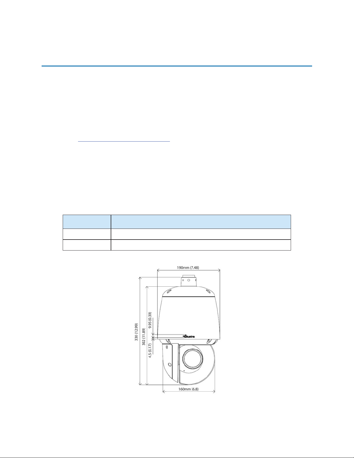
Figure 2 Physical dimensions of the Flex IR PTZ cameras (mm)
.
8200-1456-10 B0 5
Page 6
Illustra Flex 2MP Indoor and Outdoor IR PTZ Dome Quick Start Guide
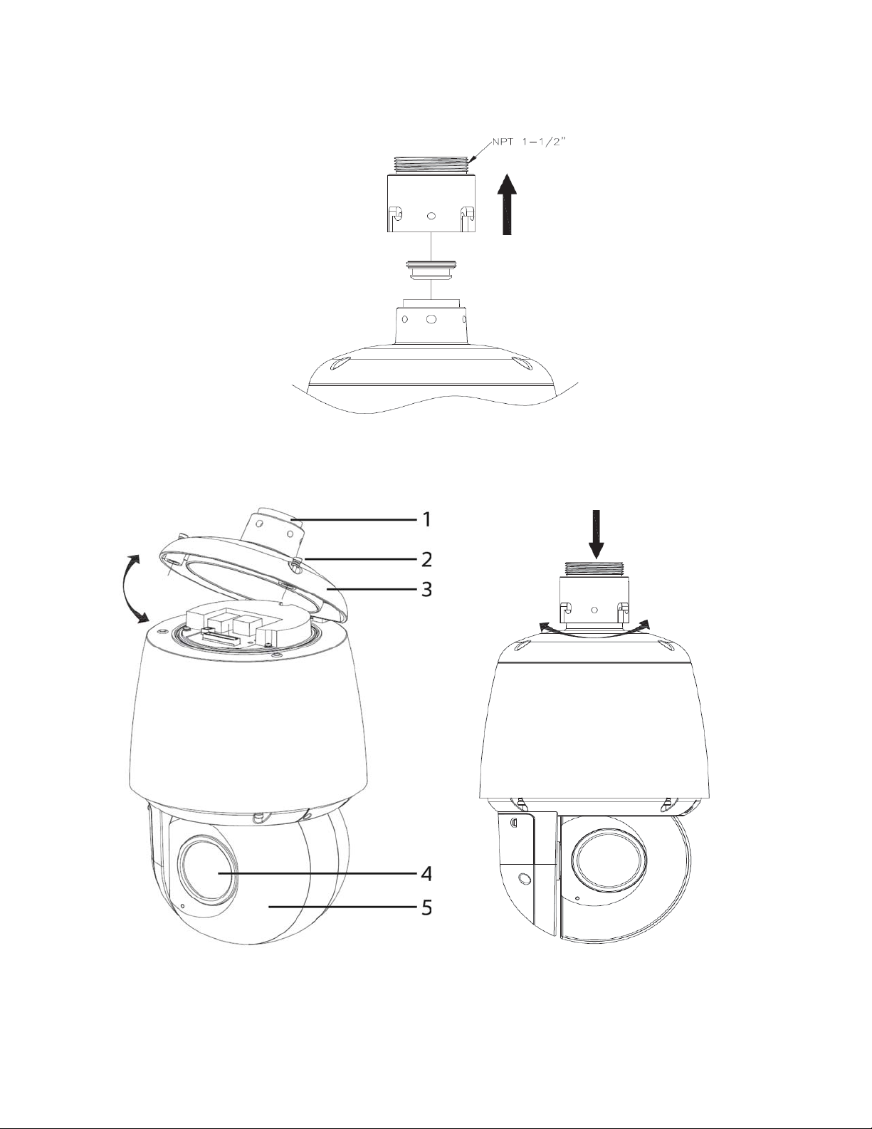
Figure 3 Physical dimensions of the mount adapter
Figure 4 Pictorial index of the camera
6 8200-1456-10 B0
Page 7
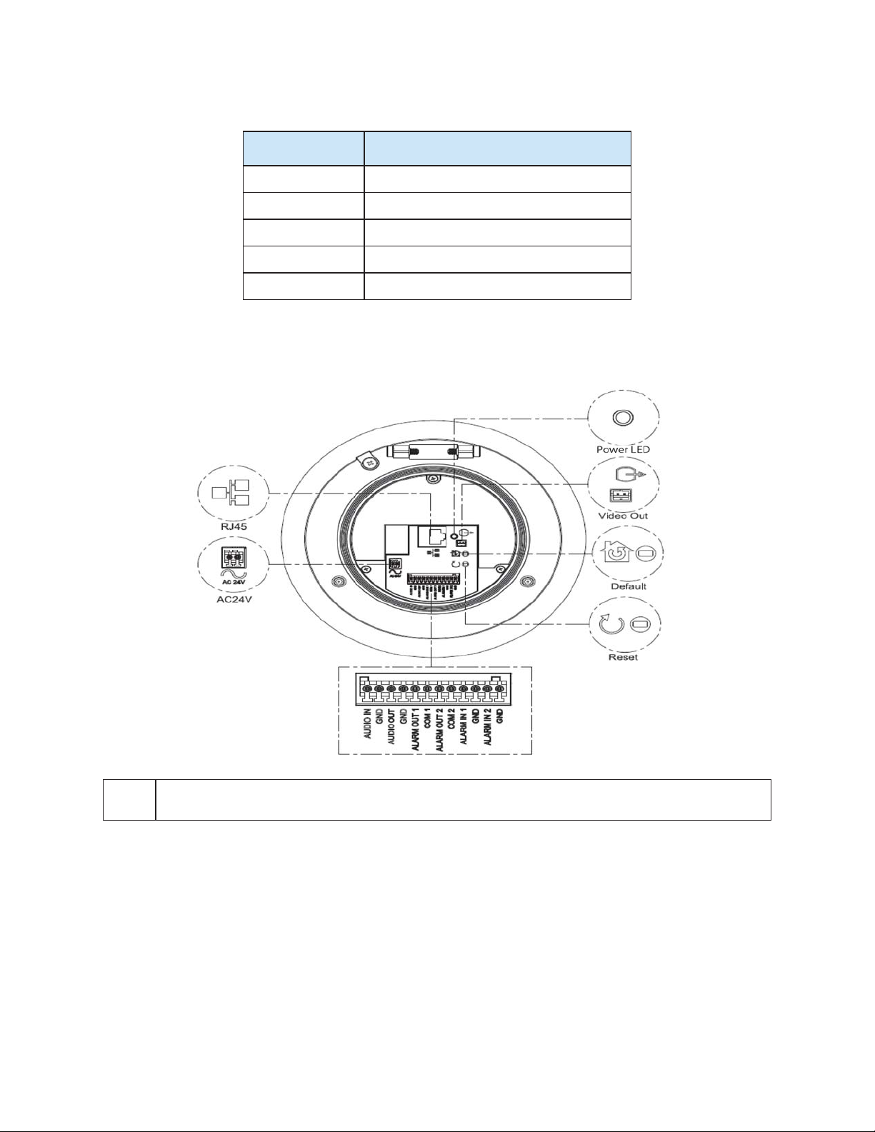
Illustra Flex 2MP Indoor and Outdoor IR PTZ Dome Quick Start Guide
Table 5 Pictorial index descriptions
Index number Description
1 NPT Pendant Cap
2 Screws (x2) to open and lock the top cover.
3 Top cover
4 Camera lens
5 Camera head
Figure 6 Pin definitions of the unit
NOTE
Connectors and field wiring terminals for external Class 2 circuits provided with marking indicating
minimum Class of wiring to be used. Class 2 shall be marked adjacent to the field wiring terminals.
8200-1456-10 B0 7
Page 8

Illustra Flex 2MP Indoor and Outdoor IR PTZ Dome Quick Start Guide
Table 7 Interior button descriptions
Button and Connectors Description
Resets to factory default by pressing and holding the button for five seconds.
Reboots the unit.
Analog out port.
Ethernet Port / PoE+
Power Connector
Figure 8 Audio and alarm pin definitions
8 8200-1456-10 B0
Page 9

Installation
In the box
Check everything in the packing box matches to the order form and the packing slip. In addition to
this guide, items below are included in the packing box:
• 1 Network IR PTZ Camera
• 1 printed Quick Start Guide
• 1 printed Regulatory document
• 1 NTSC/PAL output female BNC cable
• 1 2 position 3mm euro style plug
• 1 Torx 20 Security L-Key
• 1 Torx 6 Security L-Key
• 1 12-pin terminal connector for I/O function
• 1 Safety cable (Pre-attached to the camera)
Illustra Flex 2MP Indoor and Outdoor IR PTZ Dome Quick Start Guide
Contact your dealer if any item is missing.
Installation tools
The following tools assist with installation:
• a drill
• sc rewdrivers
• wire cutters
Checking appearance
When first unbox ing, check if there is any visible damage to the appearance of the unit and its
accessories. The protective materials used for the packaging should be able to protect the unit from
most types of accidents during transportation.
Remove the protective part of the unit when every item is checked in accordance with the list In the
box on page 9.
9 8200-1456-10 B0
Page 10

Illustra Flex 2MP Indoor and Outdoor IR PTZ Dome Quick Start Guide
Procedure 1 Accessing the connector pins
Refer to Figure 9 on page 10 for a pictorial index of acc essing the connector pins.
Step Action
1 Remove the two screws below (1) located on the top cover to open it.
Figure 9 Accessing the connector pins
-End-
Procedure 2 Connecting the wires
Step Action
This unit supports one of the following options as power supply:
1 Connect a power source:
a AC24V wired to connector and seperate RJ45 Ethernet.
OR
b PoE through RJ45 connector.
2 Connect any optional audio or digital inputs or outputs.
Note:The power source needs to be NEC Class 2 or LPS. The Indoor (PoE+ IEEE 802.3at or 24Vac)
and Outdoor (PoE U ltra 802.3bt or 24Vac) connections should be provided by a UL Listed product
and the connections shall be made in accordance with Artic le 800 of the NEC or local regulations.
-End-
10 8200-1456-10 B0
Page 11

Illustra Flex 2MP Indoor and Outdoor IR PTZ Dome Quick Start Guide
Procedure 3 Mounting the camera
Step Action
1 Refer to the Illustra mounting accessories webpage (https://www.il-
lustracameras.com/product s/accessories/mounts /) for assistanc e with this procedure.
Note:The following mount accessory part numbers are applicable with the Illustra
Flex 2MP IR PTZ camera: IFIRPTZWRECMT, IFIRPTZC2X2, RHOSW, RHOLW,
RHOTR, ROTRF, RHOWCA, ROENDC.
-End-
Procedure 4 Inserting or removing the micro SD Card
Step Action
1 Remove the two screws below (1) located on the micro SD card cover.
2 Carefully pull open the micro SD card cover to insert or remove the micro SD card into the
camera.
Figure 10 Inserting or removing the micro SD Card
Note:It is advised that you reboot the camera after inserting the micro SD card.
3 Secure the two screws loc ated on the micro SD card cover.
-End-
8200-1456-10 B0 11
Page 12

Illustra Flex 2MP Indoor and Outdoor IR PTZ Dome Quick Start Guide
IR PTZ Camera Topology
The IR PTZ camera delivers video images in real-time using the internet and intranet. It is equipped
with an Ethernet RJ-45 network interface.
The following images illustrate the network topologies of the cameras.
Figure 11 Flex IR PTZ Cameras Network Topology Type I
Figure 12 Flex IR PTZ Cameras Network Topology Type II
12 8200-1456-10 B0
Page 13

Illustra Flex 2MP Indoor and Outdoor IR PTZ Dome Quick Start Guide
Network Connection
Default IP Address
Since this is a network-based unit, an IP address must be assigned at the very first bootup. The
default IP address of the unit is 192.168.1.168 and sub mask is 255.255.255.0.
However, if you havea DHCP server in your network, the unit obtains an IP address automatically
from the DHCP server so that you do not need to change the IP address of the camera.
Note:If you assign the camera a Static IP address prior to DHCP being enabled, the camera first
reboots for approximately 30 seconds and then remains accessible at its Static IP until it connects to
a DHCP server.
• Connect to a PC direc tly: D irectly connect the camera to a PC using a standard Ethernet
cable. This requires POE switch or injector.
• Connecting a camera to a Local Area Network (LAN): To add the camera to an existing
LAN, connect the camera to the POE hub or switch on your network.
Figure 13 Network connection diagram
Default camera settings
The following table describes the default camera settings.
Network Settings Defaults
DHCP Enabled
Static IP Address 192.168.1.168
Default Username admin
Default Password admin
Note:At first login the user is prompted to change the default username and password.
13 8200-1456-10 B0
Page 14

Illustra Flex 2MP Indoor and Outdoor IR PTZ Dome Quick Start Guide
Procedure 5 Connecting from a computer
Step Action
1 Ensure the camera and your computer are in the same subnet.
2 Check whether if the network is available between the unit and the computer by pinging the
default IP address.
a Start a command prompt.
b Type “Ping 192.168.1.168”. If the message “Reply from…” appears, it meansthecon-
nection is available.
3 Start Internet Explorer and enter IP address: 192.168.1.168. A login window appears. In the
window, enter the default user name: admin and password: admin to log in.
-End-
DHCP
On initial camera startup, and after a hardware factory reset, Dy namic Host Configuration Protocol
(DHCP) is enabled by default and remains enabled until the camera receives either a DHCP address
or is assigned a Static IP address.
Procedure 6 Enable DHCP
Step Action
1 Select Setup on the Web User Interface banner to display the setup menus.
2 Select the TCP/IP tab in the Basic Configuration menu.
3 Select the Enable DHCP check box to enable DHCP and disable manual settings.
4 Select Apply tosave the settings.
The camerasearches for a DHCP server. If one is found it connects to that server. If no connection
is made to a DHCP server withintwo minutes, the camera goes to the default IP address
192.168.1.168, but continues to search for a DHCP address.
Note:If you assign the camera a Static IP address prior to DHCP being enabled, the camera first
reboots for approximately 30 seconds and then remains accessible at its Static IP until it connects to
a DHCP server.
-End-
Procedure 7 Disable DHCP
Step Action
1 Select Setup on the Web User Interface banner to display the setup menus.
2 Select the TCP/IP tab in the Basic Configuration menu.
3 Clear the Enable DHCP check box to disable DHCP andallow manual settings to be
entered.
The default setting is ‘Enabled’.
4 If Enable DHCP has been disabled:
8200-1456-10 B0 14
Page 15

Illustra Flex 2MP Indoor and Outdoor IR PTZ Dome Quick Start Guide
a Enter the IPv4 Address in the IPv4 Address text box in the form xxx.xxx.xxx.xxx.The
default setting is ‘192.168.1.168’
b Enter the Netw ork Mask in the Network Mask text box xxx.xxx.xxx.xxx. The default
setting is ‘255.255.255.0’
c Enter the Gatew ay IP address in Gateway text box xxx.xxx.xxx.xxx.
d Enter the Primary DNS Server in the Primary D NS Server text box xxx.xxx.xxx.xxx.
5 Select Apply tosave the settings.
-End-
Managing cameras with the Illustra Connect tool
In addition to using the IE browser to access your camera, you can alternatively use the provided
tool, Illustra Connect .
Illustra Connect is a management tool designed to manage your network cameras on the LAN. It can:
• help you find multiple network cameras
• set the IP addresses
• show connection status
• manage firmware upgrades
• bulk configuration
Procedure 8 Connecting to the camera using Illustra Connect
Note:
Illustra Connect can only discover devices on the same subnet as its host computer. Therefore, the
camera and the computer being used to configure it must be on the same subnet .
Step Action
1 Using a computer which is connected to the same network and subnet, ins tall the Illustra
Connect software.
The Illustra Connect softw are and the Illustra Connect manual are available to download on
www.illustracameras.com
2 When the installation is complete, run Illustra Connect.
It searches the network and displays all c ompliant devices.
3 Select the camera you want to configure, locating it by its unique MAC address.
4 Right-click the camera and select Launch Web GUI Configuration. The camera Web User
Interface displays.
-End-
15 8200-1456-10 B0
Page 16

Illustra Flex 2MP Indoor and Outdoor IR PTZ Dome Quick Start Guide
Procedure 9 Connecting to the camera using the static IP address
Step Action
1 The camera attempts to obtain an IP Address from the DHCP Server. When no DHCP
Server is available the camera is assigned a Static IP address of 192.168.1.168.
2 Open Microsoft Internet Explorer and enter the UR L of the camera as 192.168.1.168. The
camera sign in page displays.
Note:
The computer you use to configure the camera must have an IP address on the same subnet.
-End-
Procedure 10 Logging on to the camera web user interface
Step Action
1 When you select the camera, the sign in page displays. Select your preferred language from
the drop-down menu.
2 Enter the username in the Username text box. The default username is admin.
3 Enter the passw ord in the Password text box. The default password is admin.
4 Select Log in.
Note:The first time that you access the camera or after a factory reset the following two pop up
windows are visible: A pop up window that requests the user to Define a Host ID and a pop up
window that reques ts the user to select a Security Type. Please refer to the user manual for further
information on this.
5 The Live view page is visible. This displays the current view of the camera.
Note:
At first login the user is prompted to change the default username and password.
-End-
8200-1456-10 B0 16
Page 17

Illustra Flex 2MP Indoor and Outdoor IR PTZ Dome Quick Start Guide
Appendix A: Technical Specifications
The table below lists technical specifications of the Flex 2MP Indoor and Outdoor IR PTZ cameras.
General Features
Model Type Indoor IR PTZ camera Outdoor IR PTZ camera
Model No. IFS02P6INWIT IFS02P6ONWIT
Camera Body
Color
Vandal
Resistant
Rating
White White
IK10 IK10
Mechani cal Features
Dimensions Ø190x330mm Ø190x330mm
Weight approximately 5.2kg approximately 5.2kg
Pan Rotation
Angle
Tilt Angle -15° ~ +90° -15° ~ +90°
Z-axis Rotation N/A N/A
Housing
Material
Other Housing
Material
360° continuous, no end stop 360° continuous, no end stop
Aluminum Alloy Aluminum Alloy
PC PC
Video Processor
ROM/Flash Size 256 Mbytes 256 Mbytes
RAM Size 512 Mbytes 512 Mbytes
RTC Hold Up
Time
24 hours 24 hours
Image Sensor
Format 1/3" CMOS 1/3" CMOS
Capture Method Rolling Rolling
Scan Method Progressive Progressive
Lens
Design Type Motorized vari-focal electronic zoom Motorized vari-focal electronic zoom
Aperture
Range
Focal Length
Range
F/1.6(W) ~ F/4.7(T) F/1.6(W) ~ F/4.7(T)
4.3 ~ 129mm 4.3 ~ 129mm
17 8200-1456-10 B0
Page 18

Illustra Flex 2MP Indoor and Outdoor IR PTZ Dome Quick Start Guide
Focal Means Motorized Motorized
Focal Type Varifocal Varifocal
Focus Type Motorized Motorized
Auto Focus
IR Correction Optical co rrected Optical corrected
Day/Night True D/N with ICR True D/N with ICR
Horizontal
Angle of View
Vertical Angle
of View
Format 1/3" 1/3"
Continuous Auto focus or Manual
Focus
59゚ (Wide); 2.1゚ (Tele) 59゚ (Wide); 2.1゚ (Tele)
45゚ (Wide); 1.6゚ (Tele) 45゚ (Wide); 1.6゚ (Tele)
Continuous Auto focus or Manual Focus
Illuminator
Wavelength 850nm 850nm
IR Distance 25m (IEEE 802.3at Type2) 150m (IEEE 802.3bt Type 4)
Smart IR N/A N/A.
Adaptive IR
Number of IR
LED devices
Yes. Adaptive IR refers to lens position
to adjust the IR intensity of both narrow
and broad IR LEDs to have better
exposure balance.
2 6
Yes. Adaptive IR refers to lens position to adjust
the IR intensity of both narrow and broad IR LEDs
to have better exposure balance.
PoE
24 VAC Current
Draw Amps
24 VAC
Wattage
24 VAC Line
Frequency
Range
Frame Rate
Range
Maximum
Resolution and
Rate
Dynamic Range
Method
Power Supply
PoE+ IEEE 802.3at (25W) Class 4
2A 3.8A
30W 65W
47 to 63 Hz 47 to 63 Hz
PoE Ultra 802.3bt Type 3 (60W) Class 6
Video Codecs
1to60ips 1to60ips
2MP @ 60 ips 2MP @ 60 ips
Video Imaging
True WDR True WDR
8200-1456-10 B0 18
Page 19

Illustra Flex 2MP Indoor and Outdoor IR PTZ Dome Quick Start Guide
Minimum Illumination
Color: 0.2 lux 1/30s; 0.03 lux 1/4s
B&W 0.001 lux 1/4s
Color: 0.2 lux 1/30s; 0.03 lux 1/4s
B&W 0.001 lux 1/4s
Audio
Sampling Bits 16-BIT 16-BIT
Input Type SE/Line/MIC SE/Line/MIC
Input
Impedance
Maximum Input
Level
Input connector Terminal Block Terminal Block
Output Type
Impedance
Maximum
Output
Audio Features
Encoding
Method
20K/Attenuation = 0 dB 20K/Attenuation = 0 dB
2Vp-p 2Vp-p
Hi impedance Hi impedance
2Vp-p 2Vp-p
Streaming Output, Streaming Input,
Stored Audio Clips with replay
G.711 u-law and a-law G.711 u-law and a-law
Streaming Output, Streaming Input, Stored Audio
Clips with replay
Sampling Rate 8khz 8khz
Sampling Bits 16bit 16bit
Frequency
Response
Range
Input
Connector
100 to 3,600 Hz 100 to 3,600 Hz
1 (No built in mic) 1 (No built in mic)
I/O Interfaces
SD Card SDXC slot up to 128GB SDXC slot up to 128GB
Alarm Inputs 2 2
Auxiliary
Outputs
Video Output Yes Yes
IP Connector RJ-45 RJ-45
LED Indicators Green LED Green LED
Reset Buttons Reboot and Return to Defaults Reboot and Return to Defaults
2 2
Environmental
Operating
Temperature
Range
-20° ~+50°C -40° ~ +50°C
19 8200-1456-10 B0
Page 20

Illustra Flex 2MP Indoor and Outdoor IR PTZ Dome Quick Start Guide
Start-up
Temperature
Range
-20° ~+50°C -40° ~ +50°C
Water/Dust
Intrusion
IP66 IP66
Client Interfaces
Browsers
supported
IE 9 or above, Firefox, Safari, Chrome IE 9 or above, Firefox, Safari, Chrome
Networking
English (default), Arabic, Czech,
Danish, German, Spanish, French,
Languages
supported
Ethernet 10/100Base-T 10/100Base-T
Supported
Protocols
Base Protocol TCP/IP - RFC4614 TCP/IP - RFC4614
Hungarian, Italian, Korean, Japanese,
Netherlands, Polish, Portuguese,
Swedish, Turkish, Chinese Traditional,
Chinese Simplified, Russian.
TCP/IP,IPv4,IPv6,TCP,UDP,HTTP,
FTP, DHCP, WS-Discovery, DNS,
DDNS, RTP, TLS, Unicast, Multicast,
NTP, SMTP, WSSecurity, IEEE 802.1x,
PEAP, SSH, HTTPS, SSL, SOAP,
WSAddressing, CIFS, SNMP, UPnP,
RTSP, LLDP
English (default), Arabic, Czech, Danish, German,
Spanish, French, Hungarian, Italian, Korean,
Japanese, Netherlands, Polish, Portuguese,
Swedish, Turkish, Chinese Traditional, Chinese
Simplified, Russian.
TCP/IP, IPv4, IPv6, TCP, UDP, HTTP, FTP, DHCP,
WS-Discovery, DNS, DDNS, RTP, TLS, Unicast,
Multicast, NTP, SMTP, WSSecurity, IEEE 802.1x,
PEAP, SSH, HTTPS, SSL, SOAP, WSAddressing,
CIFS, SNMP, UPnP, RTSP, LLDP
Internet Layer
Addressing
Transport Layer
Data
Transmission
Network
Address
Configuration
Time
Synchronization
E-mail
Authentication
and Security
IPv4 - RFC791
IPv6 - RFC2460
TCP - RFC973
UDP - RFC768
HTTP/HTTPS - RFC2616
FTP - RFC959
SFTP
DHCP - RFC2131 Zeroconf -
RFC3927 Static IP address
LLDP
NTP - RFC1305
IETF NTP Working Group
i minute poll rate
SMTP - RFC5321
Authenticated SMTP - RFC4954
IEEE.802.1x - TLS/PEAP
HTTPS (HTTP over TLS) - RFC2818
WS-Security
Multi-level password protection
IP address filtering
HTTPS encryption
User access log
IPv4 - RFC791
IPv6 - RFC2460
TCP - RFC973
UDP - RFC768
HTTP/HTTPS - RFC2616
FTP - RFC959
SFTP
DHCP - RFC2131 Zeroconf - RFC3927 Static IP
address
LLDP
NTP - RFC1305
IETF NTP Working Group
i minute poll rate
SMTP - RFC5321
Authenticated SMTP - RFC4954
IEEE.802.1x - TLS/PEAP
HTTPS (HTTP over TLS) - RFC2818
WS-Security
Multi-level password protection
IP address filtering
HTTPS encryption
User access log
8200-1456-10 B0 20
Page 21

Illustra Flex 2MP Indoor and Outdoor IR PTZ Dome Quick Start Guide
Streaming
Firmware
Upgrade
RTP - RFC3550
RTSP - RFC2326
Unicast Streaming
Multicast RFC 1112 level 1
Browser/illustra Connect/ONVIF Browser/illustra Connect/ONVIF
RTP - RFC3550
RTSP - RFC2326
Unicast Streaming
Multicast RFC 1112 level 1
21 8200-1456-10 B0
Page 22

Illustra Flex 2MP Indoor and Outdoor IR PTZ Dome Quick Start Guide
Table 14 Flex 2MP IR PTZ Stream Tables
TWDR Off TWDR
Resolution Codec FPS range
Stream 1
(1920 x 1080) 1080p 16:9
(1280 x 720) 720p 16:9
Stream 2
(1280 x 720) 720p 16:9
(1024 x 576) PAL+ 16:9
(640 x 360) nHD 16:9
(480 x 360) 480 4:3
(384 x 288) 4:3
Stream 3
(640 x 360) nHD 16:9
H264/H264 IntelliZip
H265/H265 Intellizip
MJPEG
H264/H264 IntelliZip
H265/H265 Intellizip
MJPEG
MJPEG *2 7-15 7-15(480 x 360) 480 4:3
FPS
range
1-60 1-30(1664 x 936) 16:9
1-30 or
1-30
1-15 *1
(384 x 288) 4:3
Note:*1 - Stream 2 is res tricted to 15 FPS when Stream 1 is greater than 30 FPS
Note:*2 - Stream 3 is restricted to MJPEG only.
Note:A maximum of five concurrent streams are supported by each camera, this includes shared
streams. (Example: Stream 1 can be shared three times along with a running Stream 2 and Stream 3,
or Stream 1 can be shared five times).
Note:TWDR limits the stream to not exc eed 30 FPS even if the stream is configured to 31+ FPS.
Note:TWDR 3x is not supported for the PTZ camera.
8200-1456-10 B0 22
 Loading...