

Page 1
SpeedDome® Ultra
Drone III Fixed Camera
Installation Guide
About the Product
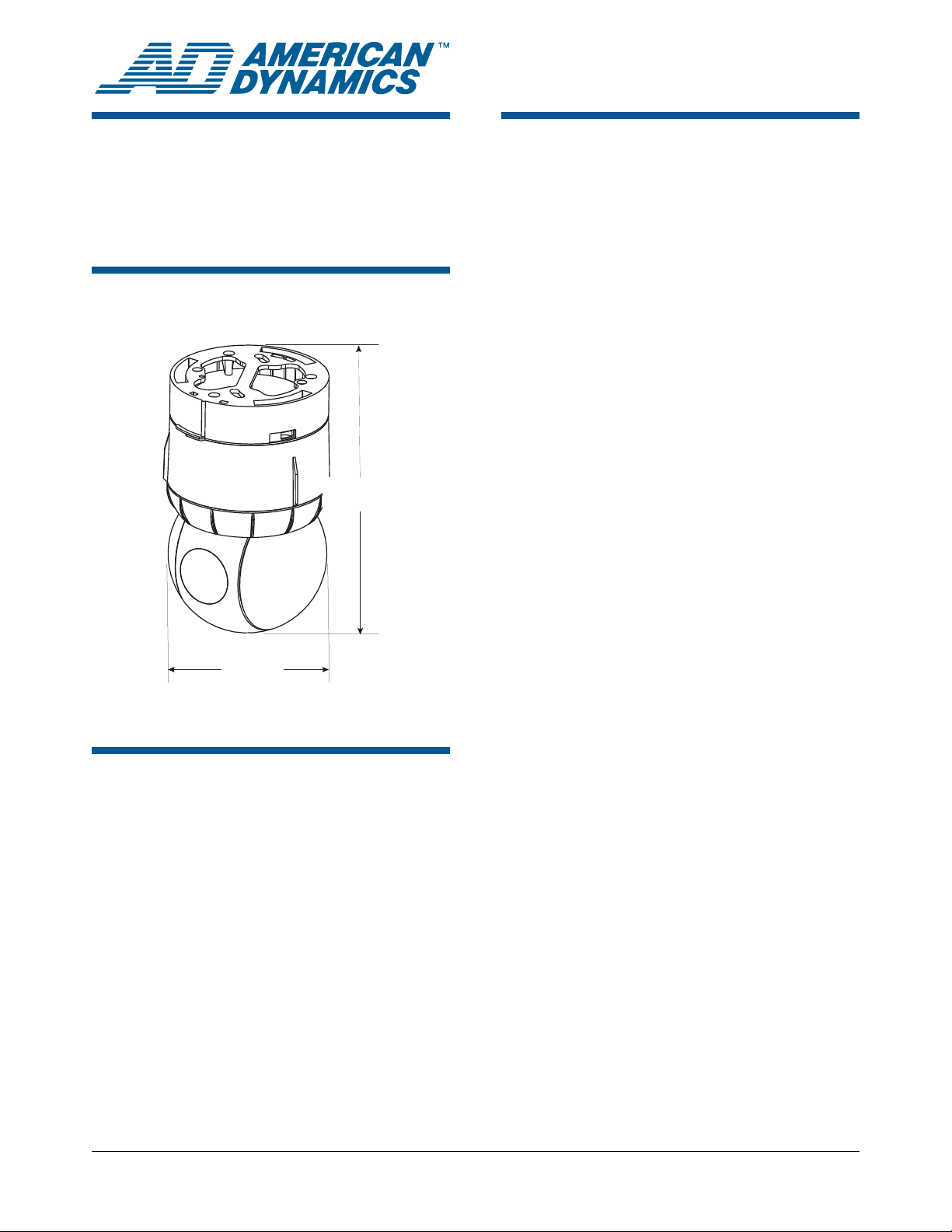
The SpeedDome Ultra Drone III system (Figure 1)
is a fixed camera housed inside the SpeedDome
Ultra chassis. Two camera types and three
different lenses are available:
• NTSC 540 TVL camera (60 Hz)
ADSDUD Series
Figure 1. SpeedDome Ultra Drone III
0.6 kg
1.45 lbs
120 mm
4.7 in.
205 mm
8 in.
• PAL 540 TVL camera (50 Hz)
• 3.8-9.5mm Auto Iris, F1.3 IR aspherical lens
• 2.5-6mm Auto Iris, F1.3 IR aspherical lens
• 9-22 mm F1.6 Auto Iris, IR lens
Each camera has manually positioned pan (360°
travel) and tilt (90°), automatic iris adjustment, and
manually set zoom and focus. The drone comes
fully assembled and is simple to install.
IMPORTANT! If you are using a VM96 video
controller and the SpeedDome Ultra Drone III
camera dome is one of the following, perform the
associated action:
• A New Drone: Reset the VM96 to update the
configuration form to a fixed camera.
• A Replacement Drone for the SpeedDome
Ultra camera dome: Delete the SpeedDome
Ultra configuration form as explained in the
VM96 Administrator’s Manual 8000-0756-05.
Then, reset the VM96 to update the
configuration form to a fixed camera.
Contents
About the Product.................................................. 1
Installation Procedure............................................ 2
Exploded View....................................................... 4
Parts Lists.............................................................. 5
Declarations .......................................................... 5
© 2006 Sensormatic Electronics Corp.
SPEEDDOME ULTRA DRONE III FIXED CAMERA 8200-0581-01, REV. A
INSTALLATION GUIDE
1 of 6
Page 2
Installation Procedure
Configure the Camera
To configure the camera, do either A or B:
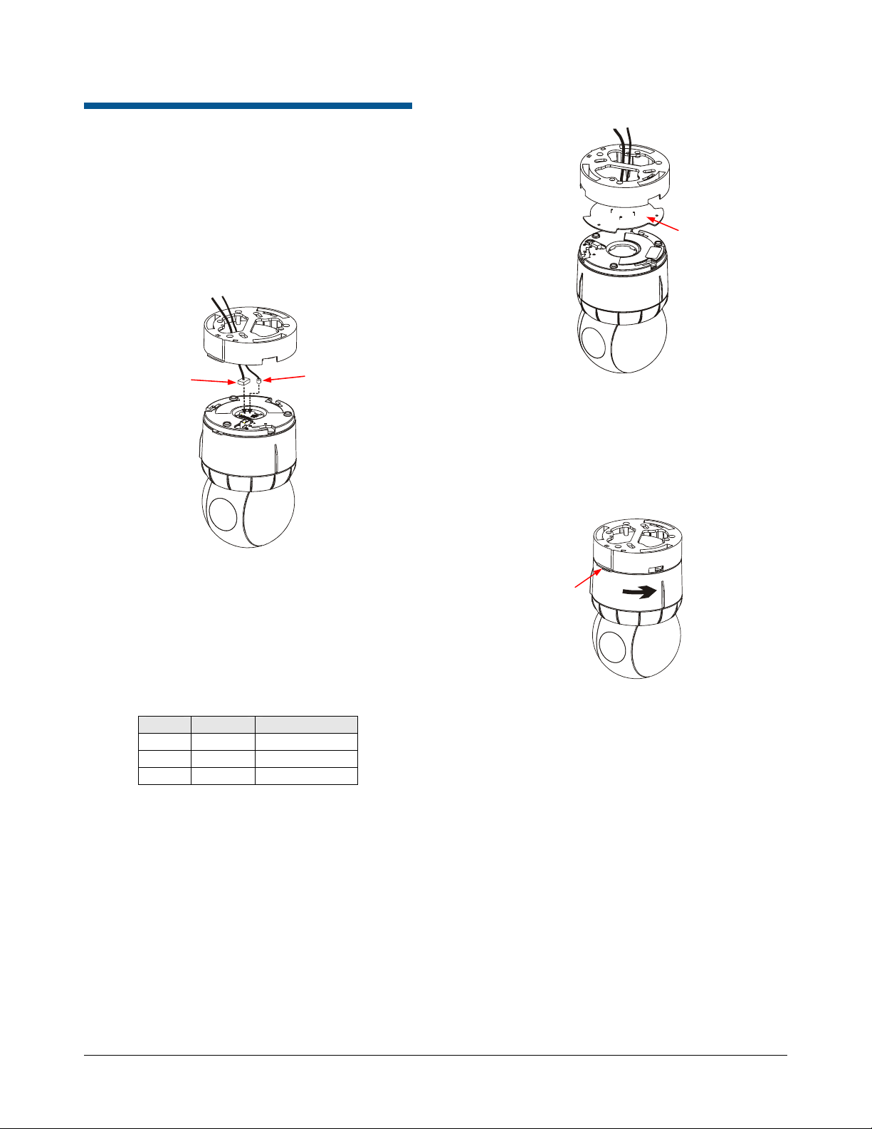
A. Direct Cable (Pigtail) Configuration
Figure 2. Attaching the Dome Cables
Figure 3. I/O Board Exploded View
I/O Board
Power
Connector
Video
Connector
1. Connect the video coaxial-wire connector to
the camera dome (
Figure 2).
2. Connect the three-wire power connector to the
camera dome (
Figure 2).
Refer to
Table 1 for the pinout arrangement of
the I/O board connector.
Table 1. I/O Board Connector (P8)
Pin Color Designation
1 Black 24Vac
2 Red Ground
3 White 24Vac
3. Attach the camera dome to the base. Refer to
Attach the Dome to the Base for instructions.
B. I/O Board Configuration
1. Ensure the I/O board is properly seated in the
dome base (
2. Attach the camera dome to the base. Refer to
Attach the Dome to the Base for instructions.
Figure 3).
Attach the Dome to the Base
1. Align the yellow alignment dot on the dome’s
cap with the yellow arrow and alignment dot on
the base (
Figure 4).
Figure 4. Attaching the Dome to the Base
Alignment
Tabs and
Dots
2. Mate the housing and eyeball assembly to the
base, and turn it counterclockwise until you
hear a click.
Note: This is a fixed camera; no communication
data lines are required.
Remove the Slot Cover
1. If necessary, tilt the eyeball to access the slot
cover containing the lens.
2. Unsnap the slot cover by gently tugging it away
from the eyeball (
now access the camera set screw.
Figure 5 on page 3). You can
SPEEDDOME ULTRA DRONE III FIXED CAMERA 8200-0581-01, REV. A
INSTALLATION GUIDE
2 of 6
Page 3

Figure 5. Removing the Slot Cover and
j
r
Adjusting the Camera
Set Screw
Zoom
Focus
Slot Cover
Adjust the Camera Settings
To make lens adjustments:
1. Loosen the set screw (
pull the camera out until the screw reaches the
front end of the slot. Retighten the set screw.
2. Adjust the camera as follows:
a. Attach a hand-held video monitor to the
video cable entering the mounting base, or
have a second person view the remote
monitor while you adjust the camera.
b. Adjust the pan and tilt to point the camera
at a target, and then adjust the zoom and
focus, as desired.
c. Combine the zoom and focus ring
adjustments to achieve the desired view.
3. Loosen the set screw, and push the camera in
until the screw contacts the rear end of the slot
Figure 6).
(
4. Retighten the set screw.
Figure 6. Repositioning the Camera
Set Screw
Figure 5), and gently
Adjust the ADSDUDH-Series Camera
If you are using an ADSDUDH-series camera,
adjust the camera as described in this section.
Note: Be sure to also follow the directions for
making the mechanical lens adjustments that are
described in the previous section,
Camera Settings
.
Figure 7. ADSDUDH-Series Camera
Focus
Ad
uste
Field of View
(Zoom)
Adjuster
ALC Adjustment
To adjust the ADSDUDH-series camera, make the
appropriate DIP switch settings:
• Low light mono mode (N.SVR / ON) – When
ON, the camera operates in monochrome mode
in reduced lighting.
• Auto White Balance (AWB / AWB.EX)
− AWB: Camera operates in the normal Auto
White Balance range (2700K – 11000K)
− AWB.EX: Camera runs in the extended Auto
White Balance range (2000K – 18000K)
• Line Lock (LL / INT)
− LL: In this mode, V-Phase is adjusted to
compensate for connected power supply
differences
− INT: Camera operates with INTernal sync
• Flickerless Mode (FL / ON): When ON,
camera reduces flicker in the image under
fluorescent lighting.
• Back Light Compensation (BLC) – When ON,
BLC improves the camera response to strong,
unwanted lighting effects behind the subject.
• Low Light Sensitivity (AGC-EX) – When set to
EX, sensitivity in low light is increased.
Adjust the
V-PHASE
Adjustment
DIP Switches
SPEEDDOME ULTRA DRONE III FIXED CAMERA 8200-0581-01, REV. A
INSTALLATION GUIDE
3 of 6
Page 4

Focus and Field of View (Zoom) Adjustments:
r
Twist the appropriate levers on the side of the
varifocal camera.
Vertical Phase Adjustment: When using an AC
power supply, this adjustment aligns the camera
phase with the power supply phase.
ALC (Iris) Adjustment: This is set at the factory
and does not normally require adjustment.
However, if required:
1. Move the AGC DIP switch to the EX (OFF)
position.
2. View the camera output on a monitor and use
a screwdriver to adjust the ALC dial.
WARNING: The tongue and grooves must be
centered over the tabs of the yoke. Failure to
properly attach the cover could result in the
cover falling off during operation. Pull on the
cover to ensure it is securely fastened.
Figure 8. Reattaching the Slot Cover
3. Move the AGC DIP switch to the AGC (ON)
position when the ALC adjustment is
completed.
Reattach the Slot Cover
1. Ensure that the slot cover tongue and grooves
already attached to the dome are centered
over the yoke tabs.
2. Reattach the slot cover by mating the tongue
and grooves together and gently pressing until
you feel a snap (
Figure 8).
Exploded View
Figure 9. SpeedDome Ultra Drone III Exploded View
1
2
3
4
5
6
7
26
25
7
89
10
11
12
Gently Push
Groove
Tongue
Yoke
Slot
Cove
13 14
Tabs
15
16
17
24
23
21
22
6
SPEEDDOME ULTRA DRONE III FIXED CAMERA 8200-0581-01, REV. A
INSTALLATION GUIDE
4 of 6
20
12
7
19
10
10
18
Page 5

Parts Lists
Table 2. SpeedDome Ultra Drone III
No. Description Qty Part Number
SpeedDome Ultra Drone III
—
2.5-6 mm NTSC
SpeedDome Ultra Drone III
—
3.8-9.5 mm NTSC
SpeedDome Ultra Drone III
—
9-22 mm NTSC
SpeedDome Ultra Drone III
—
2.5-6 mm PAL
SpeedDome Ultra Drone III
—
3.8-9.5 mm PAL
SpeedDome Ultra Drone III
—
9-22 mm PAL
1 Cover, Slot, w/o lens 1 0500-8037-01
2 Washer, FL, Type B, Reg,
SS, ¼”
3 Washer, LK, Split, Reg, Zn,
#14
4 Screw, ¼ x 20 1 *
5 Assembly, Bearing, Lens
Carriage, Drone
6 Bracket, Yoke 2 0500-8038-01
7 Tie, Cable, Nylon, 3.25 3 *
8 Bearing 1 *
9 Housing, Ultra Dome 1 0500-7255-02
10 Washer 3 *
11 Clip, Stop 1 *
12 Standoff, M3x33 3 *
13 Assembly, PCB 1 0312-2204-01
14 Cap 1 0505-1224-01
15 Label, Regulatory 1 *
16 Label, Certification 1 *
17 Base 1 0500-7257-02
18 Screw, M3x10 3 *
19 Screw, M3x6 3 *
20 Clip, Stress 1 *
21 Ring, Trim, Ultra 1 *
22 Cover, Slot, w/Lens Assy 1 0404-0353-01
23 Assembly, Bearing, Lens
Carriage, Drone
24 Yoke, Ultra Dome 1 0500-7258-01
25 Camera, w/Cable Assy 1 See Board
26 Assembly, Bearing, Lens
Carriage, Drone
* Note: Contact your technical support representative for
information on this part.
1 0101-0166-01
1 0101-0166-02
1 0101-0166-03
1 0101-0166-04
1 0101-0166-05
1 0101-0166-06
1 *
1 *
1 *
1 *
Cameras table
1 *
Table 3. Board Cameras
No. Description Qty Part Number
— 2.5-6 mm NTSC 1 2003-0053-01
— 3.8-9.5 mm NTSC 1 2003-0053-02
— 9-22 mm NTSC 1 2003-0053-03
— 2.5-6 mm PAL 1 2003-0053-04
— 3.8-9.5 mm PAL 1 2003-0053-05
— 9-22 mm PAL 1 2003-0053-06
Declarations
Regulatory Compliance
EMC...............................................47 CFR, Part 15
EN 300 330
EN 301 489
RSS 210
Safety......................................................... UL 1950
CSA C22.2 No 950
EN 60950-1
REGULATORY PRODUCT NAME:
REG ID/TYPE=VP SDU
FCC COMPLIANCE: This equipment complies with Part 15
of the FCC rules for intentional radiators and Class A digital
devices when installed and used in accordance with the
instruction manual. Following these rules provides reasonable
protection against harmful interference from equipment
operated in a commercial area. This equipment should not be
installed in a residential area as it can radiate radio frequency
energy that could interfere with radio communications, a
situation the user would have to fix at their own expense.
EQUIPMENT MODIFICATION CAUTION: Equipment
changes or modifications not expressly approved by
Sensormatic Electronics Corporation, the party responsible for
FCC compliance, could void the user's authority to operate the
equipment and could create a hazardous condition.
See “
About the Product” on page 1.
WARRANTY DISCLAIMER: Sensormatic Electronics
Corporation makes no representation or warranty with respect
to the contents hereof and specifically disclaims any implied
warranties of merchantability or fitness for any particular
purpose.
NOTICE: The information in this manual was current when
published. The manufacturer reserves the right to revise and
improve its products. All specifications are therefore subject to
change without notice.
SPEEDDOME ULTRA DRONE III FIXED CAMERA 8200-0581-01, REV. A
INSTALLATION GUIDE
5 of 6
Page 6

LIMITED RIGHTS NOTICE: For units of the Department
of Defense, all documentation and manuals were developed at
private expense and no part of it was developed using
Government Funds. The restrictions governing the use and
disclosure of technical data marked with this legend are set
forth in the definition of “limited rights” in paragraph (a) (15)
of the clause of DFARS 252.227.7013. Unpublished - rights
reserved under the Copyright Laws of the United States.
TRADEMARK NOTICE: American Dynamics and
Sensormatic are trademarks or registered trademarks of
Sensormatic Electronics Corporation. Other product names
mentioned herein may be trademarks or registered trademarks
of Sensormatic or other companies.
COPYRIGHT: Under copyright laws, the contents of this
manual may not be copied, photocopied, reproduced,
translated or reduced to any electronic medium or machinereadable form, in whole or in part, without prior written
consent of Sensormatic Electronics.
WJM_7/2006
SPEEDDOME ULTRA DRONE III FIXED CAMERA 8200-0581-01, REV. A
INSTALLATION GUIDE
6 of 6
 Loading...