

Page 1
ADACSNET
USB Control Module
Installation Guide
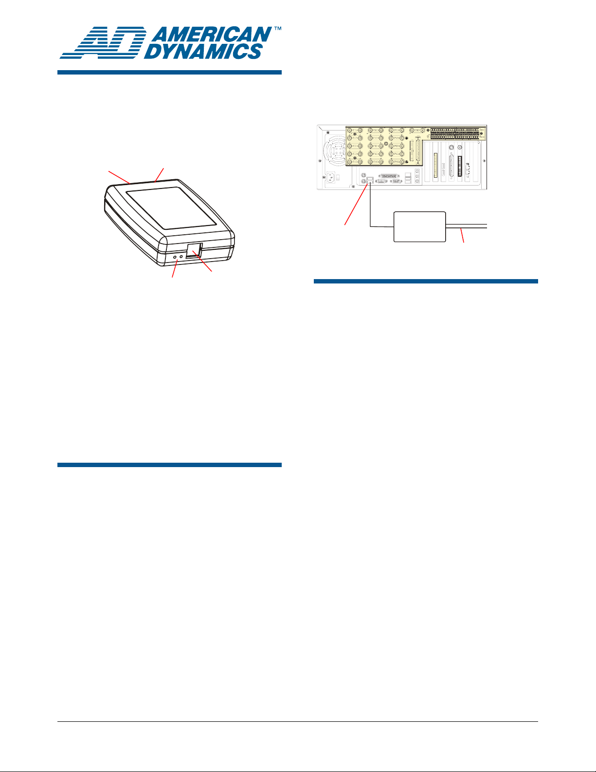
2-Pin SensorNet
Termination
Switch
Connection
The following diagram shows how to install the
control module between the host (Intellex or PC)
and a camera.
Host (Intellex shown)
The USB Control Module allows a host computer,
such as an Intellex digital video management
system (or a PC with a USB port), to control one or
more American Dynamics camera domes using the
SensorNet (RS-485) communication protocol.
This guide explains:
• Features of the module and basic hookup
• Information required to download software, if
• SensorNet Rules and network types.
Communication LEDs
required
USB Port
Features and Hookup
The USB Control Module contains the following:
• USB port: Connects to the host computer.
• Communication LEDs: A yellow LED indicates
correct USB connection by glowing steadily or
blinking. Immediately after power is turned on, a
green LED glows steadily for about 3 seconds
then turns off. This LED also blinks every time a
data packet is sent to the camera dome.
• Termination switch: Termination is indicated
by a resistor symbol near the switch. See
SensorNet Rules and Network Types in this
document for when to set the switch.
To J-Boxes or
Camera Domes
USB Port
Control
Module
SensorNet
Connection
Software Installation for Intellex Driver
Note: This procedure only applies to Intellex 3.x
and 4.x systems.
1. Exit Intellex by selecting Utility > Exit. You will
see the message: Do you wish to quit the
program?
2. Click Yes, and enter pin code 98374252.
3. Once in the Windows desktop, plug in your USB
control module. The Found New Hardware
Wizard screen appears.
4. Click Next. A Search for Suitable driver
screen appears.
5. Select the Search for a suitable driver for my
device (recommended) box and then click
Next.
6. From the Locate Driver Files screen, click the
Specify a location check box, and click Next.
7. Do one of the following:
• For Intellex DVMS, IP, and rack-mount LT,
browse to the
C:\drivers\USB Dome Control folder.
• For Intellex Ultra 4.0, browse to the
E:\drivers\USB Dome Control folder.
8. Press Open, and then OK.
© 2007 Sensormatic Electronics Corp.
ADACSNET USB CONTROL MODULE 8200-0310-01, REV. C
INSTALLATION GUIDE
1 of 6
Page 2
Software Installation for NonIntellex Systems
Note: This procedure applies to systems using
Microsoft
operating systems.
If you are not connecting the ADACSNET module
to an Intellex system, special drivers and utilities
software must be downloaded to your personal
computer that enable its use.
USB Control Module Software Utilities User Guide,
8200-0310-02, explains how to download this
software. To obtain this guide:
1. On the internet, go to
2. In the dropdown menu, click Support
3. Click SpeedDomes and Accessories, and
4. Follow the instructions on the screen to
®
Windows® 2000 or Windows® XP
http://americandynamics.net/home/default.aspx,
and click Support.
Documents, and then click Manual Index.
then scroll down and click USB Control Module
Software Utilities User Guide.
download the user guide PDF file.
SensorNet Rules and Network Types
The SensorNet communication protocol allows the
host computer and camera domes to exchange
data along a cable network (star, daisy chain, or
backbone).
SensorNet Rules
• A star network cannot have more than four
branches, one line termination per branch.
• A backbone network has a termination at each
end of the line.
• A SensorNet line cannot have more than 32
network-compatible devices.
• A network cannot have more than four
repeaters in the path of any two camera domes.
• A SensorNet line or branch cannot exceed 1km
(3300ft). Use signal repeaters only when
exceeding the maximum distance or noise is an
issue.
• Signal levels for SensorNet-compatible devices
are from 0.3–5V (1–5V is recommended).
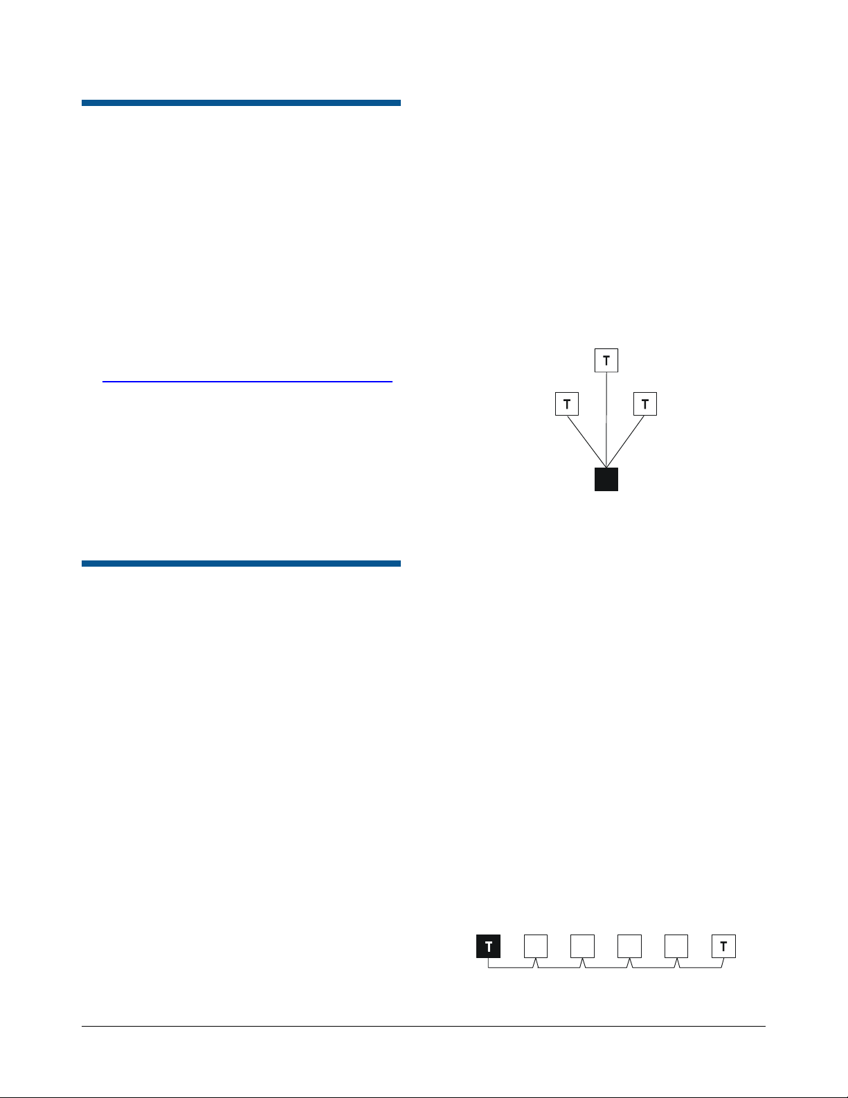
Network Types
Star Network
The star network allows you to relocate devices.
However, this network is not recommended in high
noise environments because the extra terminations
required will lower the signal to noise ratio.
A separate cable line (branch) runs from the USB
module to each device. Limit the branches to four.
The example below shows the USB module as the
hub of a star network. The module is not
terminated.
Black box = USB module, T = Terminated
Daisy-Chain/Backbone Network
Use a daisy chain network if the cable is to be
short, extended in the future, or when USB module
and camera domes are in the same room. In a
daisy chain, a separate cable connects every two
adjacent devices along the chain. Daisy chaining
makes it easy to add devices by extending the
network from a nearby device. The USB module
can connect anywhere along the cable.
Use a backbone network if the cable is to be long
and permanent. This network type operates the
same as the daisy chain, but uncut wires may be
more conductive and reliable. In a backbone, a
single cable is used. Along the cable, 2.5cm (1in)
sections are stripped, bent, and connected to each
remote device. The USB module can connect
anywhere along cable.
The example below shows the USB module at end
of a daisy chain or backbone network. The module
and the last camera dome in the chain are
terminated.
Black box = USB module, T = Terminated
Not
Terminated
ADACSNET USB CONTROL MODULE 8200-0310-01, REV. C
INSTALLATION GUIDE
2 of 6
Page 3

The example below shows the USB module inserted
into a daisy chain or backbone network. Camera
domes on both ends of the chain are terminated; the
module
Black box = USB module, T = Terminated
is not.
Not
Terminated
When J-Boxes are Used
When using the USB control module with J-Boxes,
consider the following rules (also refer to the
diagram on page
• Only use the AUX-to-HOST connection if the
distance from the HOST to the last J-BOX is
more than 1km (3300ft). Repeating is not
needed when the USB module and the last
J-BOX are less than 1km (3300ft) apart.
• From J-BOX 1 to J-BOX 2, use the HOST-toHOST connection only when the distance from
the HOST and the last J-BOX is less than 1km
(3300ft).
• If using the J-BOX to amplify the signal, it is
best to install it between 500 and 750m (16002500ft).
• Balance connection ports with domes (do not
load on one side).
4):
SensorNet Cable
SensorNet data cable. For plenum applications,
use RPPS series cable (equivalent to Belden
88442). For non-plenum applications, use RPDS
series cable (equivalent to Belden 8442).
Composite cable. For plenum applications, use
RPPCS series cable. For non-plenum applications,
use RPNCS series cable.
For further information, contact your Sales
representative for a SensorNet cable specification
sheet.
Note: In some environments, high noise on the
network may limit cable distance to less than 1km
(3300ft).
Note. Sensormatic composite cable is
recommended. This cable contains wires for power
and video. If another cable is substituted, wire
colors may be different.
If shielded cable must be used, signals may rapidly
decline as more devices are connected or its
length increases. As a result, maximum length for
shielded cable is reduced. For example, maximum
length for Belden 8760 cable is 750m (2500ft) in
ideal conditions (no noise).
ADACSNET USB CONTROL MODULE 8200-0310-01, REV. C
INSTALLATION GUIDE
3 of 6
Page 4

USB with J-Boxes
•
Balance connection ports with
domes (do not load on one side).
Unterminate when
more than one port
is used (P4–P6 or
P1–P3).
Unterminate the
HOST when it is
not at the end of
the line.
Repeating is not
needed when the
USB module and
the last J-BOX are
less than 1km
(3300ft) apart.
J-Box 1
REPEATER
305m (1000ft)
T
USB
Control
Module
91m (300ft)
J-Box 2
REPEATER
Terminate the
HOST when it is at
the end of the line.
Only use the AUX-to-HOST connection if the
distance from the HOST to the last J-BOX is
more than 1km (3300ft).
• From J-BOX 1 to J-BOX 2, use the HOST-to-
HOST connection only when the distance
from the HOST and the last J-BOX is less
than 1km (3300ft).
• If using the J-BOX to amplify the signal, it is
best to install it between 500 and 750m
(1600-2500ft).
ADACSNET USB CONTROL MODULE 8200-0310-01, REV. C
INSTALLATION GUIDE
4 of 6
Page 5

Specifications
USB Specifications
Bit rate .............................. 1.5Mb/s Low Speed,
12Mb/s Full Speed
Maximum cable length...... 3m (9.8ft) for 1.5Mb/s,
5m (16.4ft) for 12Mb/s
Specification ..................... Universal Serial Bus USB
Specification Revision 1.1
Connector ......................... USB Type B receptacle
Power source.................... From USB host controller port
(power adaptor not required)
SensorNet Specifications
Address range .................. 1 to 254 (configurable)
Bit rate .............................. 230.4Kbps
Network distance .............. 1km per node
Maximum loads................. 32 per node
Node repeaters................. SensorNet junction boxes
Topologies supported ....... Daisy chain, Backbone, or
Star
Transmission medium....... Single non-polarized
unshielded twisted pair UTP
22AWG
Connector ......................... Euro-style 2-pin removable
plug 3.5mm terminal block
Terminating resistor .......... 120 ohms, switch selectable
Physical layer ................... RS-485, transformer isolated,
2-wire
Data encoding .................. FM-0
Link layer framing ............. SDLC/HDLC
Link layer channel............. Bi-directional, half duplex
Collision avoidance........... Polling by USB Module
Application protocol .......... Proprietary
Network nodes.................. Domes, junction boxes,
secondary TouchTracker™,
and SensorNet I/O unit
Surge Protection
SensorNet:
Gas discharge tube impulse rated at:
DC breakdown voltage....................................... 90V
Insulation resistance ...............................10,000 MΩ
Capacitance ...............................................2pF max.
8/20µs impulse
discharge current ............................................. 10kA
Ten 8/20µs impulses
discharge current ............................................... 5kA
Isolation transformer coupled ......................2000Vrms
PTC re-settable fuse protects transformer
Transient voltage suppressors (TVS):
Break down voltage ................................... 7.6–9.3V
Peak current....................................................... 40A
Capacitance .....................................2000pf @ 1kHz
USB: ESD suppressors protect USB lines by
suppressing fast rising transients as specified in IEC
61000-4-2 and MIL-STD-883C (8kV discharge method).
Environmental
Operating Temperature:......... 10° to 50°C (14° to 122°F)
Relative Humidity: ....................0 to 95% non-condensing
Mechanical
Length .......................................................... 10.2cm (4in)
Width.............................................................. 7cm (2.8in)
Thickness ...................................................... 2.5cm (1in)
Weight...................................................... 0.5kg (1.1 lbs)
Power
Input voltage ..................... 5.0Vdc ±5%, 0.75W
Internal voltage
(CPU + Misc. Support)...... 3.3Vdc ±5%
ADACSNET USB CONTROL MODULE 8200-0310-01, REV. C
INSTALLATION GUIDE
5 of 6
Page 6

Other Declarations
Declarations
Regulatory Compliance
TYPE: SV USB
EMC........................................................47 CFR, Part 15
ICES-003
EN55022
CISPR 22
Safety: Complies with: .....................................................
UL 60950-1
CSA-C22.2.60950-1
EN 60950-1
IEC 60950-1
FCC COMPLIANCE: This equipment complies with Part 15
of the FCC rules for intentional radiators and Class A digital
devices when installed and used in accordance with the
instruction manual. Following these rules provides reasonable
protection against harmful interference from equipment
operated in a commercial area. This equipment should not be
installed in a residential area as it can radiate radio frequency
energy that could interfere with radio communications, a
situation the user would have to fix at their own expense.
EQUIPMENT MODIFICATION CAUTION: Equipment
changes or modifications not expressly approved by
Sensormatic Electronics Corporation, the party responsible for
FCC compliance, could void the user's authority to operate the
equipment and could create a hazardous condition.
Thank you for using American Dynamics products. We
support our products through an extensive and worldwide
network of dealers. The dealer, through whom you originally
purchased this product, is your point of contact if you have a
need for service or support. Our dealers are fully empowered
to provide the very best in customer service and support.
Dealers should contact American Dynamics at
(800) 507-6268 or (561) 912-6259 or on the web at
www.americandynamics.net.
WARRANTY DISCLAIMER: Sensormatic Electronics
Corporation makes no representation or warranty with respect
to the contents hereof and specifically disclaims any implied
warranties of merchantability or fitness for any particular
purpose.
NOTICE: The information in this manual was current when
published. The manufacturer reserves the right to revise and
improve its products. All specifications are therefore subject
to change without notice.
LIMITED RIGHTS NOTICE: For units of the Department
of Defense, all documentation and manuals were developed at
private expense and no part of it was developed using
Government Funds. The restrictions governing the use and
disclosure of technical data marked with this legend are set
forth in the definition of “limited rights” in paragraph (a) (15)
of the clause of DFARS 252.227.7013. Unpublished - rights
reserved under the Copyright Laws of the United States.
TRADEMARK NOTICE: American Dynamics and
Sensormatic are trademarks or registered trademarks of
Sensormatic Electronics Corporation. Other product names
mentioned herein may be trademarks or registered trademarks
of Sensormatic or other companies.
COPYRIGHT: Under copyright laws, the contents of this
manual may not be copied, photocopied, reproduced,
translated or reduced to any electronic medium or machinereadable form, in whole or in part, without prior written
consent of Sensormatic Electronics.
WJM 02/2007
ADACSNET USB CONTROL MODULE 8200-0310-01, REV. C
INSTALLATION GUIDE
6 of 6
 Loading...