

Page 1
SensorNet/Manchester
Distribution Panel
Installation Guide
Figure 1. SensorNet/Manchester Distribution
Panel
ADACSNETD / ADACSNETDP
About this Guide
About the Product
The SensorNet/Manchester Distribution Panel:
• Provides signal amplification for SensorNet and
Manchester multi-point dome control
communications.
• Has two Host ports A and B. When used with a
dual MP CPU system, Host A port can connect
to one MP CPU, while the Host B port can
connect to the other MP CPU to support hot
switching.
• Has 16 secondary device ports (two connectors
per port) to accommodate home-run dome
wiring or multiple daisy-chained connections to
domes, J-boxes, or other distribution panels.
Note: Each port has an LED that indicates data
is being received.
Note: Since Manchester communication is
simplex (one-way), received data never occurs
on the 16 secondary device ports. Therefore, to
indicate Manchester operation, the LEDs for
ports 1 through 3 are constantly ON with ports 4
through 16 OFF.
• Designed to be wall-mounted or installed in a
19-inch EIA/IEC equipment rack.
This installation guide explains how to install the
SensorNet/Manchester Distribution Panel. The
ADACSNETDP includes an external power
module.
If you need assistance...
Contact your Sales Representative.
Warning and Cautions
WARNING: RISK OF ELECTRIC
SHOCK! Disconnect AC power to the
panel.
CAUTION-Electrostatic Sensitive
Device: Follow proper handling
procedures to prevent component failure.
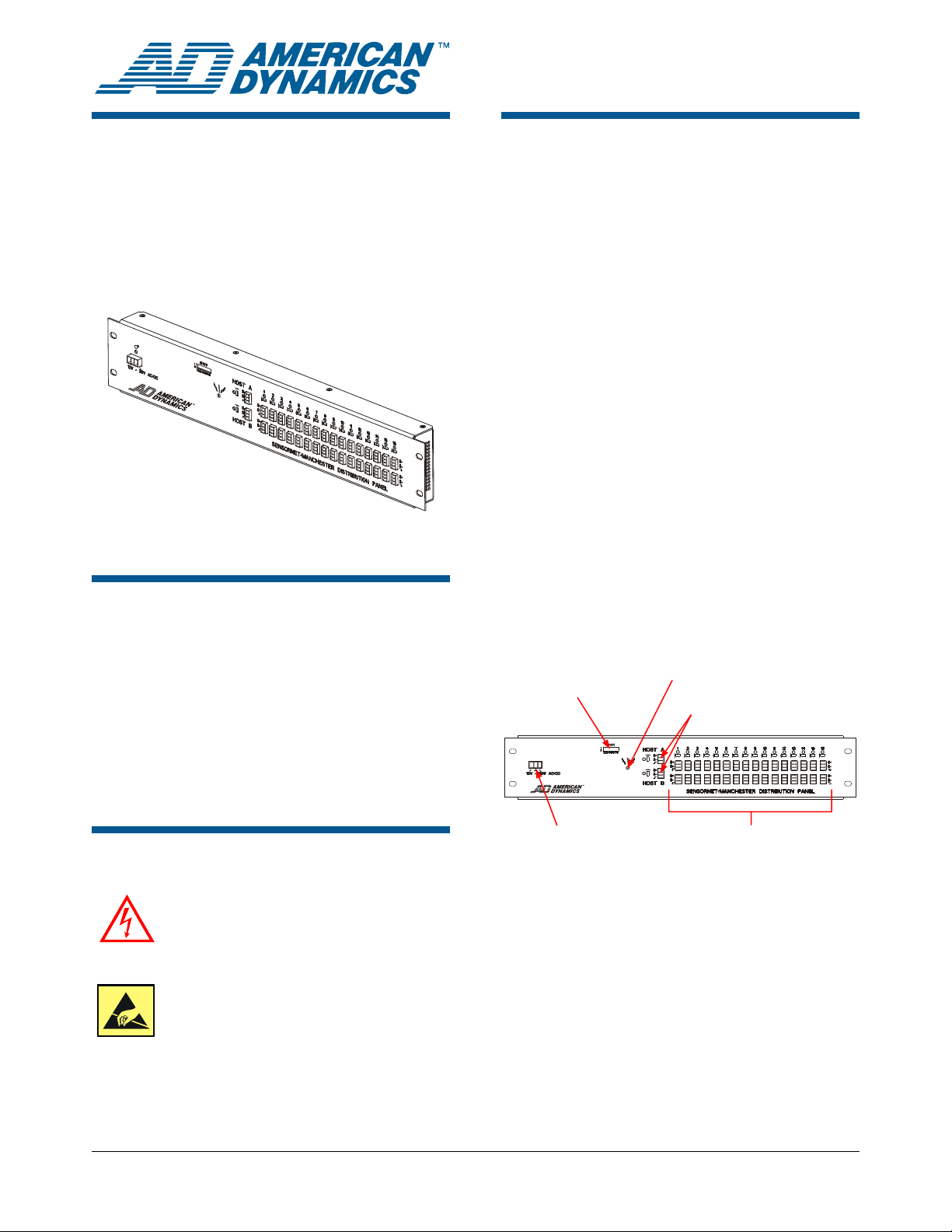
Figure 2. Distribution Panel components
SW1 DIP Switches
Power
Connecto
12–30V AC/DC
Note: The Noise Indicator may indicate improper
line termination, line noise, packets cut short, or
other false carrier detection situations that might
occur when a too-short packet fragment is
detected.
r
Noise Indicator
Host Connectors,
LEDs, and Switches
Output Data Connectors,
LEDS, and Switches
© 2008 Sensormatic Electronics Corp.
SENSORNET/MANCHESTER DISTRIBUTION PANEL 8200-0712-01, REV. F
INSTALLATION GUIDE
1 of 5
Page 2

Installation
Parts
Install kit 0352-0331-01, used with the 0404-0383-01
distribution panel. It includes grounding hardware.
Part
User Guide, Video Sys Comm
Protocols & Cable Networks
Con,p,Eur,3.5,22-16g,1x3p
Con,p,Eur,.2c,28-12g,3p,orange
Cbl,3c,18g,16x30,pvc,cm
Lbl,blnk,pap,therm,3.5x3,wh,rl
Scr,m,php,st,z,6-32x1/4
Wsh,int th,#6,st,z
Nut,hx,ss,6-32
Tm,spade,#6,22-16aw
Required Tools
• Phillips screwdriver (rack and wall installations)
• Hammer (wall installation)
• Drill with bits (wall installation, if needed)
• Pencil (wall installation)
• Leveling device (wall installation)
Qty
1
34
1
16.50
1
1
1
1
2
Part Number
8000-2573-19
2109-0510-03
2109-0254-02
6002-0024-01
2450-0008-01
2804-7106-06
2845-6300
2836-0001-03
2141-0027-01
Configuration Considerations
SW1 Switch Settings
Pos. 0 Setting 1 Setting
50µs Turnaround
1
2 Manchester SensorNet
3 Not used Not used
4 Not used Not used
5 Not used Not used
6 Not used Not used
7 LED Test Mode
8
Notes:
(1)
Normally, SW1 position 1 is set to “1”. Setting SW1
position 1 to “0” might benefit certain legacy domes
located a short distance away.
(2)
To test, set SW1 position 7 to “0.” All LED indicators
should turn on, except for the noise indicator.
(3)
For engineering test only. Set SW1 position 8 to “1”.
(1)
Time
State Machine Test
(3)
Mode
Termination Switches
> 50µs Turnaround
Time
(2)
Normal Operation
Normal Operation
(1)
Rack Installation
1. Secure the distribution panel to the equipment
rack.
2. For proper surge protection, attach the panel to
a grounded rack or connect a conductor from
the panel to ground using the hardware
provided. Ensure metal-to-metal contact.
Wall Installation
1. At the rear of the distribution panel, measure
from key slot to key slot to determine
screw/anchor locations. Then install suitable
screws and anchors (not supplied) in the wall to
which the panel is to attach. The wall and
hardware must support 5.1kg (11.2 lbs).
2. Attach the panel to the pre-mounted screws.
Then lock the panel in place by inserting a third
screw into the wall centered adjacent to its top
surface.
3. For proper surge protection, connect a
conductor from the enclosure to ground using
the hardware provided. Ensure metal-to-metal
contact.
A termination switch is on each of the 16
secondary device ports and the two Host ports.
These switches are recessed so they cannot be
accidentally tripped. Set the switch to:
• “Terminate” if it is located at the end of the line.
• “Not terminate” if multiple wires connect to the
port.
For further information, see user guide 8000-257319 supplied.
SENSORNET/MANCHESTER DISTRIBUTION PANEL 8200-0712-01, REV. F
INSTALLATION GUIDE
2 of 5
Page 3

Surge Protection
Specifications
Electrical
Power Source ..............................External power module
Transformer: Multiple panels may be connected up
to the maximum VA rating of the transformer.
Input................................. 12–30V, DC or AC, (50–60Hz)
Certified Limited Power Source
NEC Class 2
Isolation not required
Power Consumption ..................................................8VA
Indicators:
Power-On/Heartbeat ...................................Green LED
Noise Detect ..................................................Red LED
Host A and B Receive Data ....................... Yellow LED
Channels 1–16 Receive Data .................... Yellow LED
Protection ............................Internal primary current fuse
Inrush limiting
DC Isolation
Cable to transformer ....................................... 5m (16.5ft)
18AWG (0.823mm
Input Connector ............ Euro-style 3-pin removable plug
5.06mm (0.2in) terminal block
Surge Protection .......................Transguard rated at 60V,
250A, 1.5 Joules
Gas discharge tube impulse rated at 10kA
Design Tolerance:
Input voltage minimum 11V DC or AC without drop out
Input voltage >36V DC or AC may damage equipment
Input frequency .............................................. 47–63Hz
Allowable drop out .............................................150ms
Power connector pin assignments:
Pin Label Notes
1 and 3
2 Ground
12V – 30V
AC/DC
Connect 12–30V AC or
DC power to these pins in
any polarity
Used for surge protection
and data line shields
2
), 3-conductor
SensorNet/Manchester Ports
Transient Voltage Suppressors (TVS):
Break Down Voltage................................... 7.6–9.3Vdc
Peak Current ..........................................................40A
Capacitance ........................................ 2000pf @ 1kHz
Gas discharge tube impulse rated at:
DC Break Down Voltage.....................................90Vdc
Insulation Resistance ...................................10,000MΩ
Capacitance .................................................... 2pf Max
8/20µs Impulse Discharge Current ....................... 10kA
Ten 8/20µs Impulses Discharge Current ................5kA
Isolation transformer coupled...........................2000Vrms
PTC re-settable fuse protects transformer
Mechanical
Overall dimensions (LxWxD).....................481x87x34mm
(18.9 x 3.4 x 1.3in)
Body length ............................................. 446mm (17.6in)
Weight................................................... 0.75kg (1.66 lbs)
Mounting ..........EIA-310-D 19in. Electronic Racks (2 RU)
IEC 60297-1 482.6mm Electronic Racks (2 RU)
Wall mount
Compatibility
Compatible with all versions of American Dynamics
SpeedDomes, Manchester receiver drivers, J-Boxes,
and control systems using SensorNet or Manchester
protocols
Environmental
Operating Temperature................................–10° to 50°C
(14° to 122°F)
Storage Temperature ................................... –40° to 70°C
(–40° to 158°F)
Relative Humidity .....................0 to 95% non-condensing
SENSORNET/MANCHESTER DISTRIBUTION PANEL 8200-0712-01, REV. F
INSTALLATION GUIDE
3 of 5
Page 4

Data Communication
Specification SensorNet Manchester
Address Range 1 to 254 1 to 64
Bit Rate 230.4kbps 31kbps
1km (3300ft) per cable segment if
Network Distance
repeaters are used
1.5km (5000ft) per cable segment if
repeaters are not used
Maximum Loads 32 per cable segment 3 per run
Cable Segment
Repeaters
SensorNet Junction boxes and distribution
panels
Topologies Daisy Chain, Backbone, or Star Daisy Chain
Transmission Medium
Single, non-polarized, unshielded twisted
pair UTP 22AWG (0.326mm
2
)
Euro-style 3-pin removable plug
Connector
3.5mm (0.14in) terminal block, shield not
used
Pin 1 .............................S+ (Orange wire)
Connector Pin
Assignments
Pin 2 .............................. S– (Yellow wire)
Pin 3 ................ Ground (Shield not used)
Terminating Resistor 120Ω, switch selectable 120Ω, switch selectable
Physical Layer RS-485, transformer-isolated, 2-wire RS-485, transformer-isolated, 2-wire
Data Encoding FM-0 Manchester
Link Layer Framing SDLC/HDLC Proprietary
Link Layer Channel Bi-directional, half-duplex Simplex
Collision Avoidance Polling by primary host controller device N/A
Application Protocol Proprietary Proprietary
Host Controller Devices
ADMPCPU, ADTT16E primary
Touch Tracker
MegaPower LT, ADACSNET SensorNet
®
, MegaPower® 48 Plus,
USB module, and previous AD SensorNet
host/controller products
Domes, Distribution Panels, Junction
Secondary Devices
Boxes, Secondary Touch Tracker, and
SensorNet I/O Unit
Notes:
• The host input ports will be used in sequence whenever the previous input port is not receiving data.
• When used in a dual MegaPower CPU system, the HOST A port connects to one CPU, and the HOST B port connects to
the other CPU to support hot-switching capability.
1.5km (5000ft)
Distribution panels
2
Single twisted pair 18AWG (0.823mm
) (Belden
8760), polarized, shielded
Euro-style 3-pin removable plug
3.5mm (0.14in) terminal block
Pin 1 ............................................. S+ (Black wire)
Pin 2 ............................................. S– (White wire)
Pin 3 ....................................Ground (Shield used)
ADMPCPU, AD2091, MegaPower 48 Plus, and
previous AD SensorNet host controller products
Domes
SENSORNET/MANCHESTER DISTRIBUTION PANEL 8200-0712-01, REV. F
INSTALLATION GUIDE
4 of 5
Page 5

Other Declarations
Declarations
Regulatory Compliance
EMC ...................................................................47 CFR, Part 15
ICES-003
EN 55022
Immunity.....................................................................EN50130-4
Safety ........................................................................ UL 60950-1
CSA C22.2.60950-1
EN 60950-1
IEC 60950-1
REGULATORY PRODUCT NAME:
TYPE: ADVDB
FCC COMPLIANCE: This equipment complies with Part 15
of the FCC rules for Class A digital devices when installed and
used in accordance with the instruction manual. Following
these rules provides reasonable protection against harmful
interference from equipment operated in a commercial area.
This equipment should not be installed in a residential area as
it can radiate radio frequency energy that could interfere with
radio communications, a situation the user would have to fix at
their own expense.
EQUIPMENT MODIFICATION CAUTION: Equipment
changes or modifications not expressly approved by
Sensormatic Electronics Corporation, the party responsible for
FCC compliance, could void the user's authority to operate the
equipment and could create a hazardous condition.
See “
About the Product” on page 1.
Thank you for using American Dynamics products. We
support our products through an extensive and worldwide
network of dealers. The dealer, through whom you originally
purchased this product, is your point of contact if you have a
need for service or support. Our dealers are fully empowered
to provide the very best in customer service and support.
Dealers should contact American Dynamics at
(800) 507-6268 or (561) 912-6259 or on the web at
www.americandynamics.net.
WARRANTY DISCLAIMER: Sensormatic Electronics
Corporation makes no representation or warranty with respect
to the contents hereof and specifically disclaims any implied
warranties of merchantability or fitness for any particular
purpose.
NOTICE: The information in this manual was current when
published. The manufacturer reserves the right to revise and
improve its products. All specifications are therefore subject to
change without notice.
LIMITED RIGHTS NOTICE: For units of the Department
of Defense, all documentation and manuals were developed at
private expense and no part of it was developed using
Government Funds. The restrictions governing the use and
disclosure of technical data marked with this legend are set
forth in the definition of “limited rights” in paragraph (a) (15)
of the clause of DFARS 252.227.7013. Unpublished - rights
reserved under the Copyright Laws of the United States.
TRADEMARK NOTICE: American Dynamics and
Sensormatic are trademarks or registered trademarks of
Sensormatic Electronics Corporation. Other product names
mentioned herein may be trademarks or registered trademarks
of Sensormatic or other companies.
COPYRIGHT: Under copyright laws, the contents of this
manual may not be copied, photocopied, reproduced,
translated or reduced to any electronic medium or machinereadable form, in whole or in part, without prior written
consent of Sensormatic Electronics.
MDR 05/2008
www.americandynamics.net
SENSORNET/MANCHESTER DISTRIBUTION PANEL 8200-0712-01, REV. F
INSTALLATION GUIDE
5 of 5
 Loading...