

Page 1
ADG-410
082896
021898WL/tf
Parts Manual
1995 thru 1998
American Dryer Corporation
88 Currant Road
Fall River, MA 02720-4781
Telephone: (508) 678-9010 / Fax: (508) 678-9447
E-mail: techsupport@amdry.com
ADC Part No. 450166
Page 2

Retain This Manual In A Safe Place For Future Reference
American Dryer Corporation products embody advanced concepts in engineering, design, and safety. If this
product is properly maintained, it will provide many years of safe, efficient, and trouble-free operation.
ONLY properly licensed technicians should service this equipment.
OBSERVE ALL SAFETY PRECAUTIONS displayed on the equipment or specified in the installation/
operator's manual included with the dryer.
WARNING:
WARNING:The dryer must never be operated with any of the back guards, outer tops, or
We have tried to make this manual as complete as possible and hope you will find it useful. ADC reserves the
right to make changes from time to time, without notice or obligation, in prices, specifications, colors, and
material, and to change or discontinue models.
UNDER NO CIRCUMSTANCES should the door switch or the heat circuit devices
ever be disabled.
service panels removed. PERSONAL INJURY or FIRE COULD RESULT.
Important
For your convenience, log the following information:
DATE OF PURCHAS E MODEL NO.
DIS TRI BUT ORS N AME
Serial Number(s)
ADG-410
Replacement parts can be obtained from your distributor or the ADC factory . When ordering replacement parts
from the factory, you can FAX your order to ADC at (508) 678-9447 or telephone your orders directly to the
ADC Parts Department at (508) 678-9010. Please specify the dryer model number and serial number in
addition to the description and part number, so that your order is processed accurately and promptly.
The illustrations on the following pages may not depict your particular dryer exactly. The illustrations are a
composite of the various dryer models. Be sure to check the descriptions of the parts thoroughly before
ordering.
INSTRUCTIONS TO BE FOLLOWED IN THE EVENT THE USER
SMELLS GAS MUST BE POSTED IN A PROMINENT LOCATION. THE
INSTRUCTIONS TO BE POSTED SHALL BE OBTAINED FROM THE
LOCAL GAS SUPPLIER.
Page 3

Table of Contents
Front Panel Assembly, Automatic Door .............................................................................2, 3
Solid Back Panel Assembly................................................................................................... 4
Automatic Door Pneumatics Assembly ................................................................................. 5
Left Automatic Load Door Assembly..................................................................................6, 7
Right Automatic Load Door Assembly ...............................................................................8, 9
Right Front Control Door Assembly............................................................................... 10, 11
Left Control Door Assembly ................................................................................................12
Lint Basket Assembly .........................................................................................................13
Base Solenoid Junction Box Assembly .......................................................................... 14, 15
Sprinkler Option Control Panel Assembly ...................................................................... 16, 17
Right Hand Electrical Panel Wireway Channels.............................................................. 18, 19
Top of Right Hand Electrical Panel
For models mfd. as of August 26, 1997 ............................................................................... 20, 21
Top of Right Hand Electrical Panel
For models mfd. prior to August 26, 1997 ........................................................................... 22, 23
Bottom of Right Hand Electrical Panel .......................................................................... 24, 25
All Door, All Tilt, Base Electrical Junction Box Control Panel Assembly......................... 26, 27
Drive Motor Assembly
For models mfd. as of November 14, 1997................................................................................. 28
Drive Motor Assembly
For models mfd. prior to November 14, 1997............................................................................. 29
Drive Shaft Assembly
For models mfd. as of November 14, 1997................................................................................. 30
Drive Shaft Assembly
For models mfd. prior to November 14, 1997............................................................................. 31
Speed Reducing Idler Shaft Assembly
For models mfd. prior to November 14, 1997....................................................................... 32, 33
Tumbler and Idler Shaft Assembly.......................................................................................34
Rotational Sensor Assembly Diagram ..................................................................................35
Fan Motor Assembly ..................................................................................................... 36, 37
Temperature Sensor Bracket...............................................................................................38
DSI Module Assembly .........................................................................................................39
Front Burner Box Assembly .......................................................................................... 40, 41
Rear Burner Box Assembly ............................................................................................ 42, 43
Sail Switch Assembly ..........................................................................................................44
Air Jet Assembly.................................................................................................................45
Gas Piping Assembly ................................................................................................46, 47, 48
Tilt Switch Assembly ..........................................................................................................49
Tilt Piston Mount Assembly ................................................................................................50
Post Assembly ....................................................................................................................51
Pneumatic Assembly
For 1 Automatic Door ............................................................................................................... 52
Pneumatic Assembly
For 2 Automatic Doors.............................................................................................................. 53
Pneumatic Panel Assembly
For One-Way Tilt Models..................................................................................................... 54, 55
Pneumatic Panel Assembly
For Two-Way Tilt Models..................................................................................................... 56, 57
Optional Sprinkler Assembly......................................................................................... 58, 59
Sprinkler Temperature Probe Junction Box Assembly ................................................... 60, 61
Steam Coil Assembly .................................................................................................... 62, 63
Sprinkler Solenoid Assembly...............................................................................................64
Tumbler Retaining Wheel Mount Assembly..........................................................................65
Guard Assemblies
For Two-Way Tilt Models..................................................................................................... 66, 67
Side Panel Assemblies................................................................................................... 68, 69
Front Base & Front Top Panel Assemblies ...........................................................................70
End of Cycle Light Assembly ...............................................................................................71
Selector Switch, Nameplate, and Mounting Base Chart ........................................................72
Page 4
2
NOTE: Same assembly used as Rear Panel assembly for T wo-Door Models.
Fr ont Panel Assembly, Automatic Door
American Dryer Corporation 88 Currant Road / Fall River, MA 02720-4781
Page 5

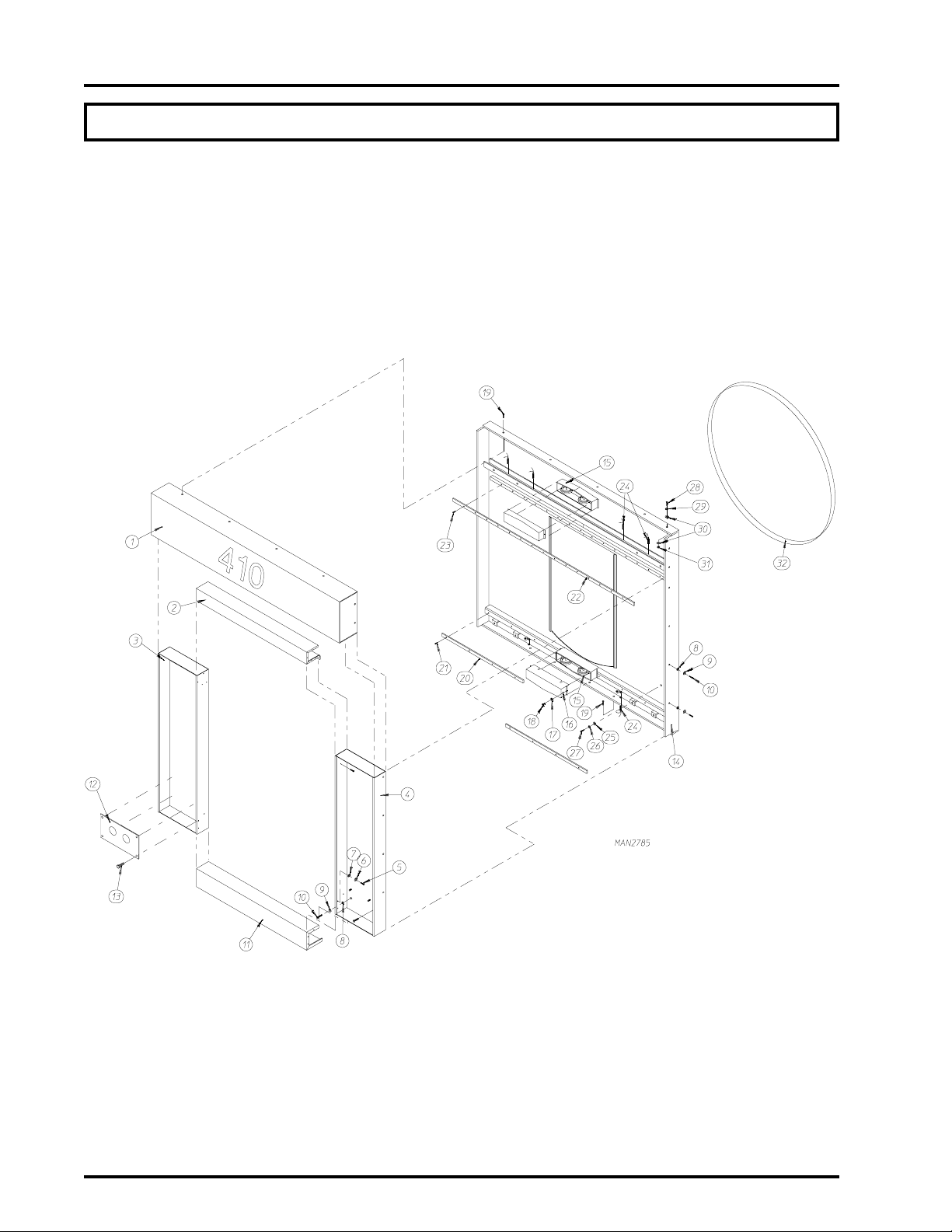
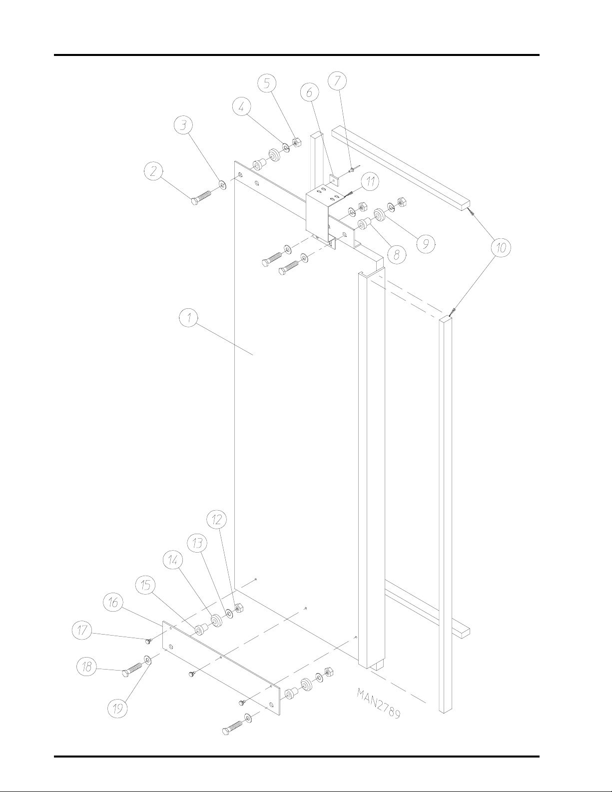
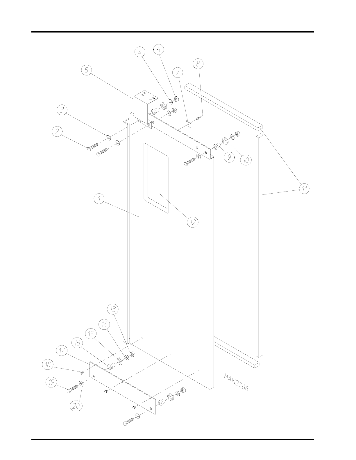
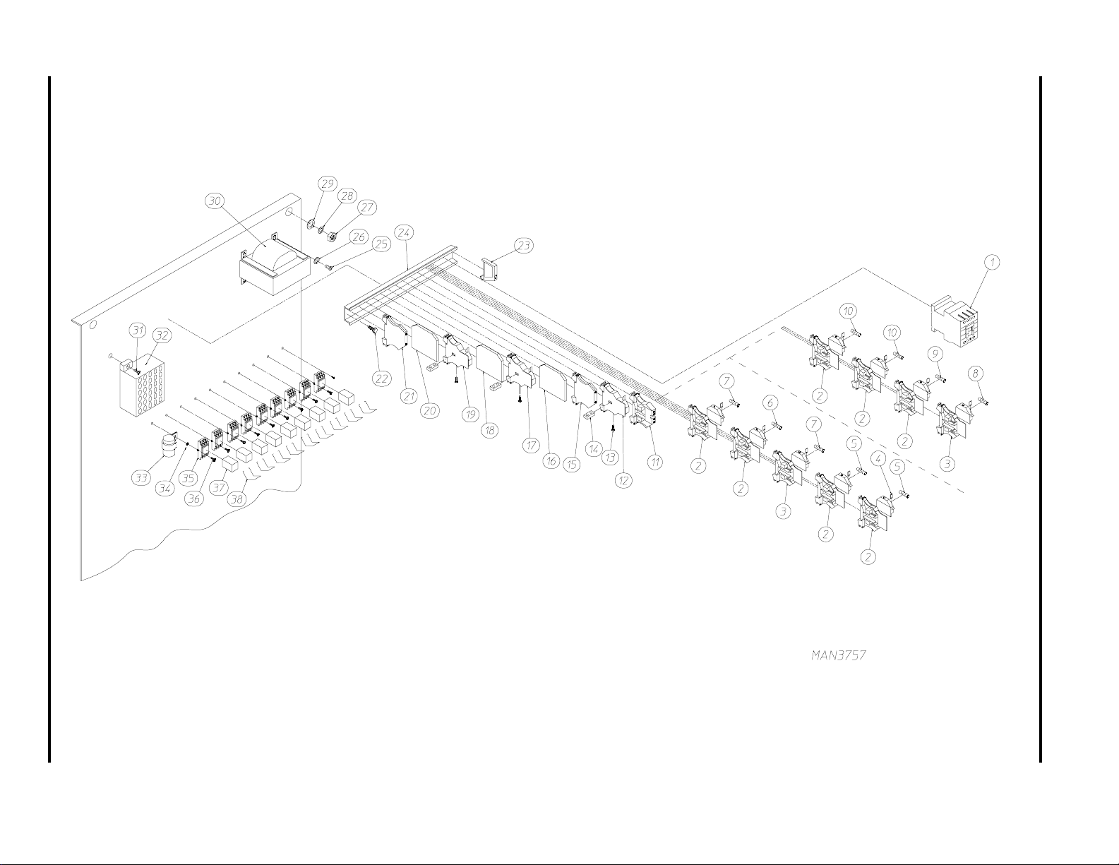
Front Panel Assembly , Automatic Door
NOTE: Same assembly used as Rear Panel assembly for T wo-Door Models.
Illus. No. Part No. Qty Description
1* 814059 1 Upper Guard
2* 814058 1 Middle Guard
3* 881388 1 Left Control Cabinet
4* 881387 1 Right Control Cabinet
5 150510 6 1/4-20 x 3/4" Hex Head Machine Bolt
6 153007 6 1/4" Lock Washer
7 153018 6 1/4" Flat Washer
8 153001 10 5/16" Flat Washer
9 153002 10 5/16" Lock Washer
10 150501 10 5/16-18 x 3/4" Hex Head Machine Bolt
11* 814057 1 Bottom Guard
12 332938 1 Feed Through Plate
13 150309 4 Crimptite Screw
14 881386 1 Front Panel Assembly
1 5 --------- 4 Retaining Wheel Assembly (see
16 814070 2 Retaining Wheel Cover
17 153018 4 1/4" Flat Washer
18 150309 4 Crimptite Screw
19 150523 10 1/4-20 x 3/4" Hex Washer Head Machine Bolt
20 170362 2 Bottom Door Track
21 154312 14 #10-32 x 3/4" Socket Head Cap Screw
22 170363 1 Upper Door Track
23 154312 16 #10-32 x 3/4" Socket Head Cap Screw
24 821452 4 Door Switch Assembly
25 153004 12 3/8" Flat Washer
26 153005 12 3/8" Lock Washer
27 150617 12 3/8-16 x 1" Hex Head Bolt
28 150605 4 1/2-13 x 1-1/2" Hex Head Bolt
29 153026 4 1/2" Lock Washer
30 153050 8 1/2 x 1/16 Flat Washer
31 152011 4 1/2-13 Hex Nut
32 116009 1 200" x 1-3/8" Felt Tumbler
page 65)
3
* Specify color when ordering
Telephone: (508) 678-9010 Fax: (508) 678-9447
Page 6
4
NOTE: For 1 Door Models
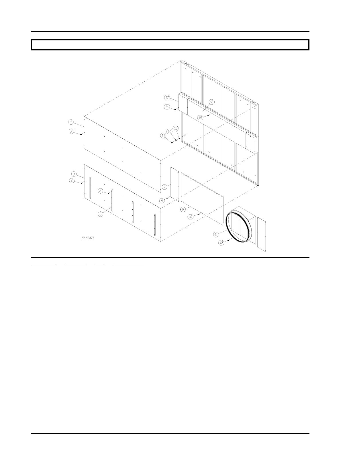
Solid Back Panel Assembly
Illus. No. Part No. Qty Description
1* 334615 1 Solid Back Panel Top Cover
2 150522 26 1/4-20 x 1/2" TEK Screw
3* 334616 1 Solid Back Panel Bottom Cover
4 150522 26 1/4-20 x 1/2" TEK Screw
5 170344 4 Nylon Back Guide
6 150311 12 #10 x 3/4" Hex Head Crimptite Screw
7* 334542 2 Piston Cover
8 150309 12 #10-16 x 1/2" Hex Head Crimptite Screw
9* 334541 1 Rear Left Base Panel
10 150522 6 1/4-20 x 1/2" TEK Screw
11* 814069 1 Transition Piece (One Door Dryer ONLY)
12 150522 6 1/4-20 x 1/2" TEK Screw
13 150617 12 3/8-16 x 1" Hex Head Bolt
14 153005 12 3/8" Lock Washer
15 153004 12 3/8" Flat Washer
16 150522 12 1/4-20x 1/2" TEK Screw
17* 334521 2 Solid Back Panel Wheel Cover
18* 334520 1 Solid Back Panel Center Cover
19 150522 14 1/4-20 x 1/2" TEK Screw
* Specify color when ordering
American Dryer Corporation 88 Currant Road / Fall River, MA 02720-4781
Page 7
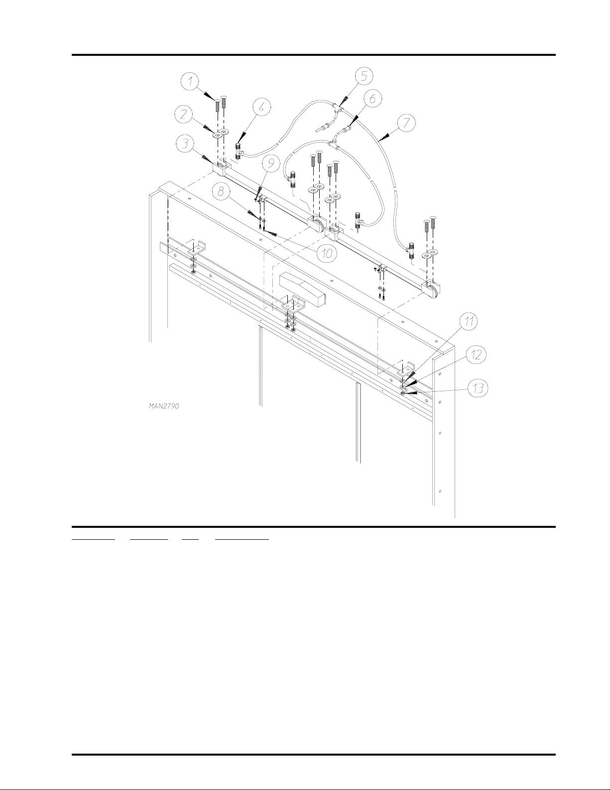
Automatic Door Pneumatics Assembly
5
Illus. No. Part No. Qty Description
1 150308 8 #8-32 x 2-1/2" Long Machine Screw
2 153000 8 #8 Flat Washer
3 100432 2 Cable Cylinder
4 128978 4 1/8" NPT x 1/4" Tube Flow Control
5 143156 2 1/4" Poly Tee
6 143154 2 1/4" Brass Poly Connector
7 143110 A/R 1/4" Poly Flo Tubing (sold by the foot)
8 153012 4 #8 Star Washer
9 152001 4 #8-32 Hex Nut
10 150103 4 #8-32 x 3/4" Phillips Head Machine Screw
11 153000 8 #8 Flat Washer
12 153012 8 #8 Star Washer
13 152001 8 #8-32 Hex Nut
A/R - As Required
Telephone: (508) 678-9010 Fax: (508) 678-9447
Page 8
6
Left Automatic Load Door Assembly
American Dryer Corporation 88 Currant Road / Fall River, MA 02720-4781
Page 9

Left Automatic Load Door Assembly
Illus. No. Part No. Qty Description
1* 881392 1 Left Automatic Load Door Assembly Complete
(includes illus. nos. 1-11)
881391 1 Left Automatic Load Door ONLY
2 150112 3 1/4-20 x 1-1/4" Hex Head Machine Screw
3 153018 3 1/4" Flat Washer
4 153007 3 1/4" Lock Washer
5 152002 3 1/4-20 Hex Nut
6 102102 1 Magnet
7 154200 1 5/32" Pop Rivet
8 170367 2 Stainless Steel Stationary Bushing
9 170366 2 Stainless Steel Sealed Wheel
10 115995 80" Felt Gasket (sold by the inch)
11 334134 1 Automatic Door Bracket
12 152002 2 1/4-20 Hex Nut
13 153007 2 1/4" Lock Washer
14 170366 2 Stainless Steel Sealed Wheel
15 170367 2 Stainless Steel Stationary Bushing
16* 334558 1 Lower Trolley ONLY
17 150301 3 #8-18 x 7/16" Hex Head Machine Screw
18 150112 2 1/4-20 x 1-1/4" Hex Head Machine Screw
19 153018 2 1/4" Flat Washer
7
* Specify color when ordering
Telephone: (508) 678-9010 Fax: (508) 678-9447
Page 10
8
Right Automatic Load Door Assembly
American Dryer Corporation 88 Currant Road / Fall River, MA 02720-4781
Page 11

Right Automatic Load Door Assembly
Illus. No. Part No. Qty Description
1* 881390 1 Right Automatic Load Door Assembly Complete
(includes illus. nos. 1-12)
881389 1 Right Automatic Load Door ONLY
2 150112 3 1/4-20 x 1-1/4" Hex Head Machine Screw
3 153018 3 1/4" Flat Washer
4 153007 3 1/4" Lock Washer
5 334134 1 Automatic Door Bracket
6 152002 3 1/4-20 Hex Nut
7 102102 1 Magnet
8 154200 1 5/32" Pop Rivet
9 170367 2 Stainless Steel Stationary Bushing
10 170366 2 Stainless Steel Sealed Wheel
11 115995 80" Felt Gasket (sold by the inch)
12 102215 1 Glass Window
170730 1 Glass Adhesive (10.3 oz. Cartridge)
13 152002 2 1/4-20 Hex Nut
14 153007 2 1/4" Lock Washer
15 170366 2 Stainless Steel Sealed Wheel
16 170367 2 Stainless Steel Stationary Bushing
17* 334558 1 Lower Trolley ONLY
18 150301 3 #8-18 x 7/16" Hex Head Machine Screw
19 150112 2 1/4-20 x 1-1/4" Hex Head Machine Screw
20 153018 2 1/4" Flat Washer
9
* Specify color when ordering
Telephone: (508) 678-9010 Fax: (508) 678-9447
Page 12
10
Right Front Control Door Assembly
Illus. No. Part No. Qty Description
1 122351 1 Large "EMERGENCY STOP" (Mushroom Head) Button
2 122419 1 "EMERGENCY STOP" Nameplate
3* 122360 1 2-Position Selector Switch
4* 122413 1 "TILT OFF - TILT ON" Nameplate
5 123201 1 Green "CONTROL VOLTAGE ON" Button
6 122410 1 Power "ON" Nameplate
7 123212 1 Incandescent Bulb - 24 VAC
8 123204 1 Red "CONTROL VOLTAGE OFF" Button
9 122421 1 Power "OFF" Nameplate
10** 123200 1 Amber "Push Button" Lighted Operator
11** 122420 1 Engraved "SPRINKLER STOP" Nameplate
12** 123211 1 120 VAC Incandescent Bulb
American Dryer Corporation 88 Currant Road / Fall River, MA 02720-4781
Page 13

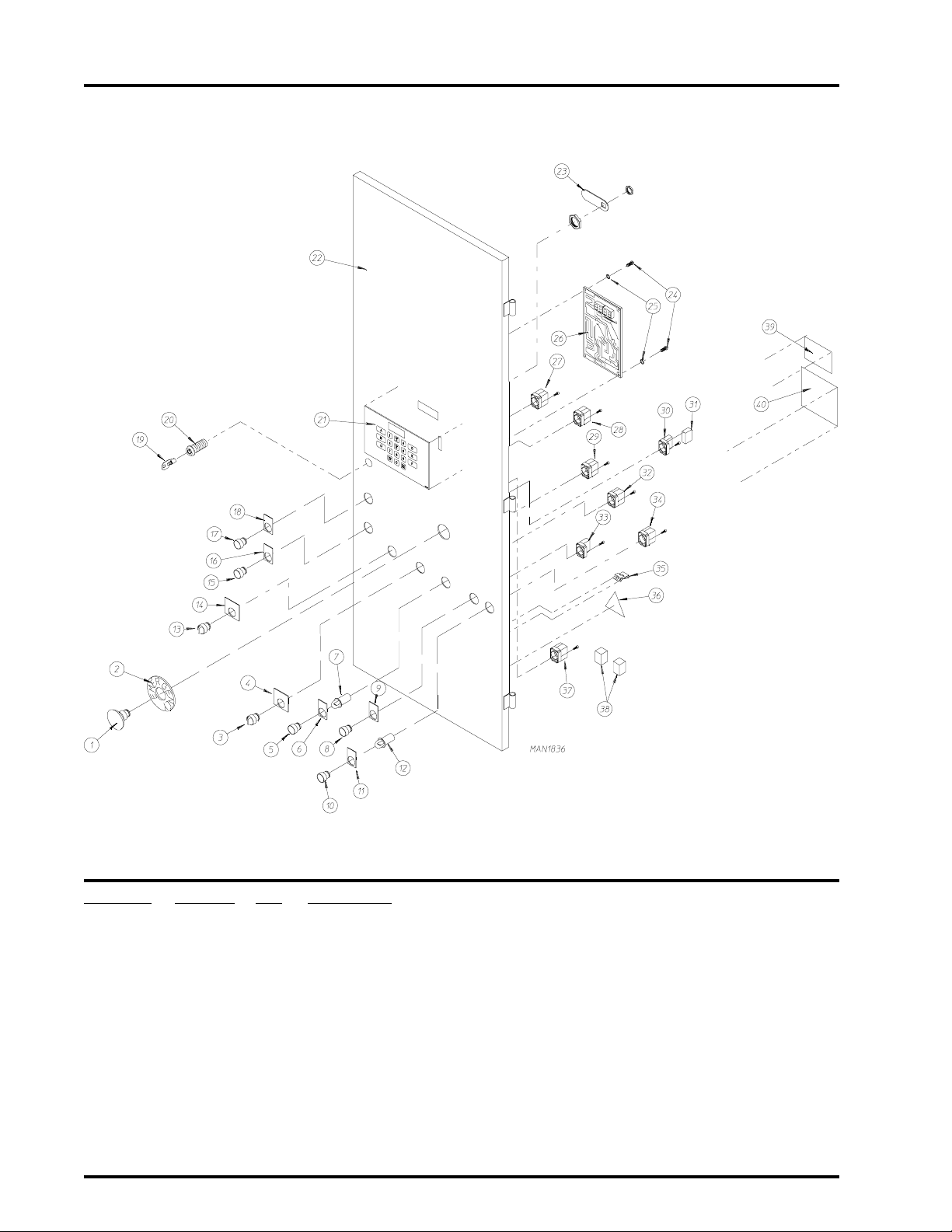
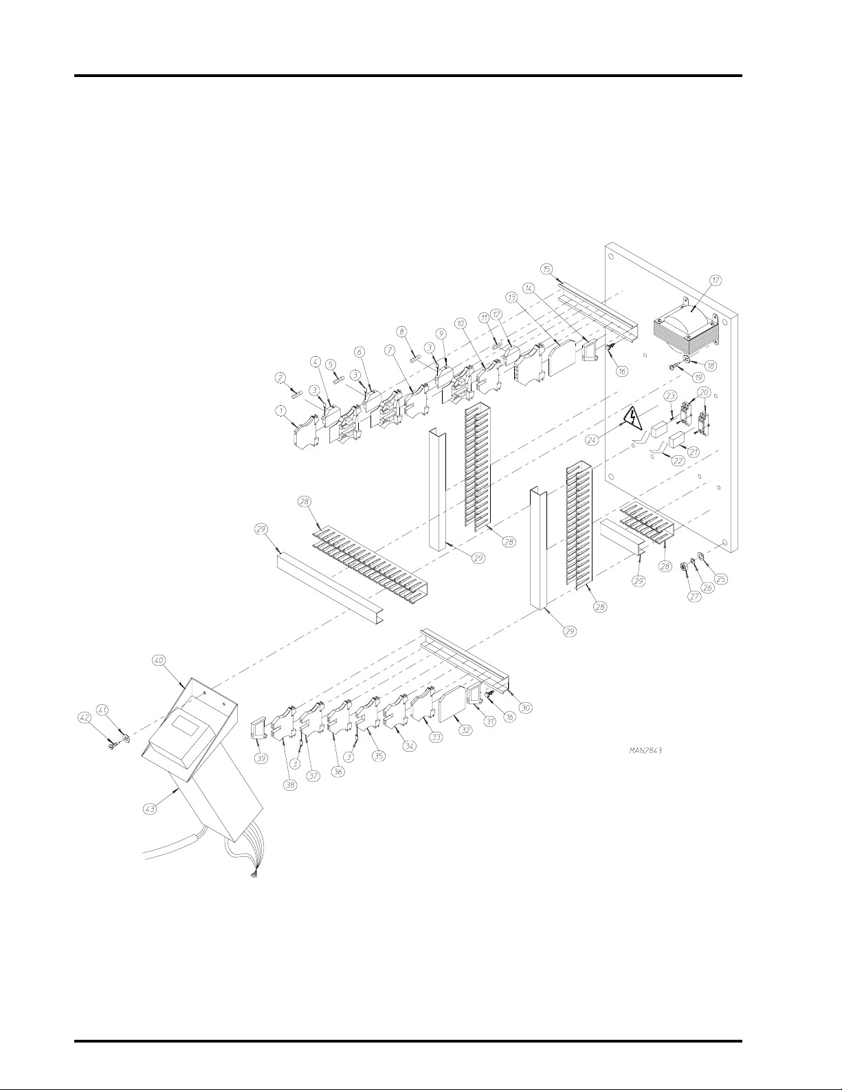
Right Front Control Door Assembly (continued)
Illus. No. Part No. Qty Description
1 3 ---------- - Selector Switch
(refer to Selector Switch, Nameplate, and Mounting Base Chart on page 71)
14 ---------- - Nameplate
(refer to Selector Switch, Nameplate, and Mounting Base Chart on page 71)
15 123202 1 White "Push Button" Operator
16 122416 1 "REVERSE" Nameplate
17 123203 1 Black "Push Button" Operator
18 122415 1 "FORWARD" Nameplate
19 160140 1 ACE® XX4451 Key ONLY
20 160050 1 ACE® Control Door Lock ONLY less Key (keyed to #XX4451)
21 112535 1 OPL English Keyboard Label Assembly
112276 1 OPL Stick-On Labels (English ONLY) ... Not Illustrated
112275 1 OPL Stick-On Labels
(Spanish, Italian, and Hebrew ONLY) ... Not Illustrated
112277 1 3-Language OPL Stick-On Labels
(English, Spanish, and Hebrew ONLY) ... Not Illustrated
112278 1 5-Language OPL Stick-On Labels
(Italian, Dutch, French, German, and Chinese ONLY) ... Not Illustrated
22*** ---------- 1 Right Hand Control Door Assembly
(contact factory with dryer serial number)
23 160014 1 Cam ONLY
24 150005 2 #6-32 x 1/4" Phillips Round Head Machine Screw
25 153010 2 #6 Star Washer
26 881129 1 Phase 5 OPL Reversing Microprocessor with External PLC Interface
137227 1 Phase 5 OPL Reversing Microprocessor with Interface Connector
27 132396 1 Mounting Base with 1 N.O. and 1 N.C. Contact Block
28 132396 1 Mounting Base with 1 N.O. and 1 N.C. Contact Block
29 132394 1 Mounting Base with 1 Normally Open (N.O.) Contact Block
30 132395 1 Mounting Base with 1 Normally Closed (N.C.) Contact Block
31 132387 1 Normally Closed (N.C.) Contact Block
32 132388 1 Normally Open (N.O.) Contact Block with Direct Supply Base
33 132395 1 Mounting Base with 1 Normally Closed (N.C.) Contact Block
34** 132388 1 Normally Open (N.O.) Contact Block with Direct Supply Base
35 121509 3 Metal Clip-On Mount
36 122424 1 Power Warning Label "Small Triangle"
37 --------- - Mounting Base
(refer to Selector Switch, Nameplate, and Mounting Base Chart on page 71)
38 --------- - Mounting Base
(refer to Selector Switch, Nameplate, and Mounting Base Chart on page 71)
39 112905 1 "Phase 5 Computer System" Label
40 112534 1 "Phase 5 Computer Location" Label
11
* For 2-Way Tilt models ONLY
* * For models with the Sprinkler Option
*** Specify color when ordering
Telephone: (508) 678-9010 Fax: (508) 678-9447
Page 14
12
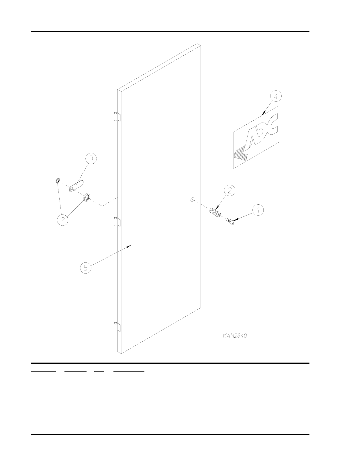
Left Control Door Assembly
Illus. No. Part No. Qty Description
1 160140 1 Key ONLY for Control Door Lock (#XX4451)
2 160050 1 Control Door Lock Less Key (Keyed to #XX4451)
3 160014 1 Cam
4 112360 1 ADC Logo
5* 821334 1 Left Hand Control Door ONLY
* Specify color when ordering
American Dryer Corporation 88 Currant Road / Fall River, MA 02720-4781
Page 15
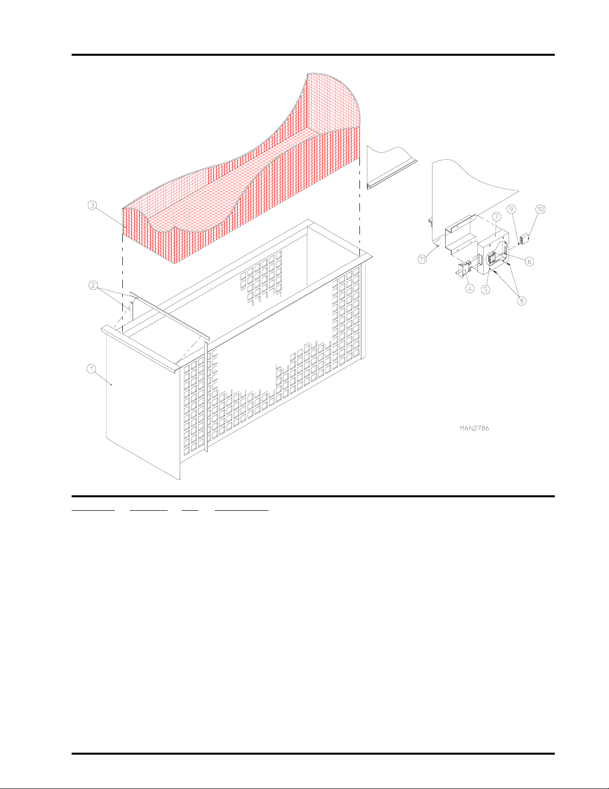
Lint Basket Assembly
13
Illus. No. Part No. Qty Description
1* 881393 1 Lint Drawer Assembly Complete
(includes illus nos. 1 and 2)
2 117602 7 Noise Suppressor Tape (sold by the foot)
3 814036 1 Lint Screen
4 122116 1 Lint Drawer Switch ONLY
5 122605 2 4-Pin Socket Connector ONLY
6 122701 4 Socket Terminal ONLY
122801 1 Pin/Socket Extraction Tool (NOT ILLUSTRATED)
7 800264 1 Lint Drawer Switch Box Assembly Complete
(includes illus. nos. 4 through 7)
304034 1 Lint Drawer Switch Box ONLY
8 150301 4 #8-18 x 7/16" Phillips Pan Head TEK Screw
9 122700 4 Pin Terminal ONLY
10 122604 2 4-Pin Connector ONLY
11 150301 2 #8-18 x 7/16" Phillips Pan Head TEK Screw
* Specify color when ordering
Telephone: (508) 678-9010 Fax: (508) 678-9447
Page 16
14
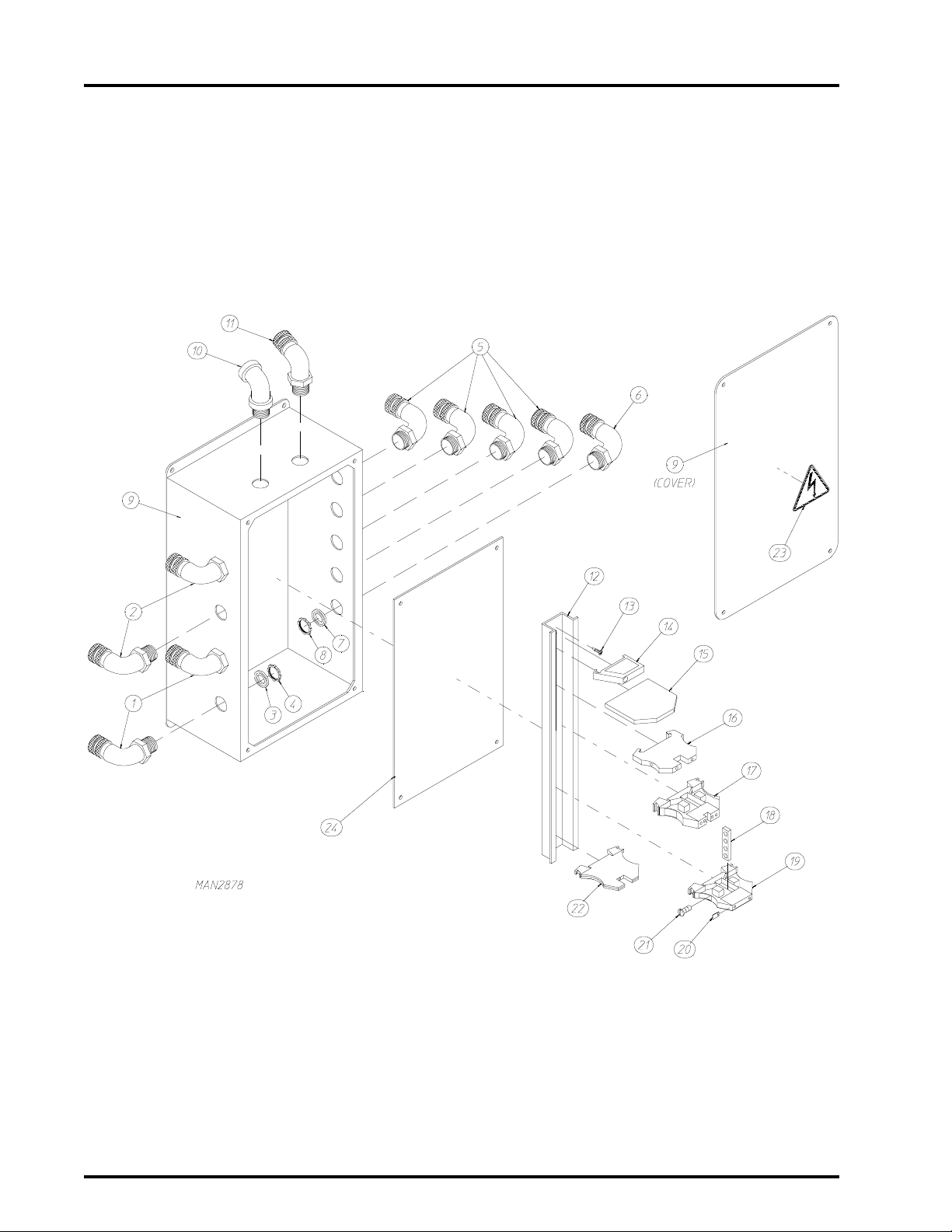
Base Solenoid Junction Box Assembly
American Dryer Corporation 88 Currant Road / Fall River, MA 02720-4781
Page 17

Base Solenoid Junction Box Assembly
Illus. No. Part No. Qty Description
1 120651 2 1/2" N.P.T. 90º Cord Grip (Blue)
2 120650 2 1/2" N.P.T. 90º Cord Grip (White)
3 120914 4 1/2" N.P.T. Metal Clad Sealing Washer
4 120915 4 1/2" N.P.T. Lock Nut
5 120650 2 1/2" N.P.T. 90º Cord Grip (White)
6 120651 2 1/2" N.P.T. 90º Cord Grip (Blue)
7 120914 4 1/2" N.P.T. Metal Clad Sealing Washer
8 120915 4 1/2" N.P.T. Lock Nut
9* 121107 1 Junction Box
10 120111 1 1/2" Liquid Tite 45º Fitting
11 120657 1 3/4" N.P.T. 45º Cord Grip (Yellow)
12 120768 9 DIN Mounting Rail (Sold by the inch)
13 150309 4 #10-16 x 1/2" Hex Head Crimptite Screw
14 120765 1 End Stop
15 120766 1 End Plate
16 120758 24 Feed Through Terminal Block
17 120761 1 Four Position Feed Through Terminal Block
18 120991 1 Four Pole Bus Bar
19 120752 4 Terminal Block with Test Point
20 120999 7 Blank Marking Tag
21 120998 4 Bus Bar Screw
22 120750 4 Ground Terminal Block
23 122425 1 Triangle Warning Label
24 332847 1 Base Solenoid Junction Box Panel ONLY
15
* Due to the various options, Box is shipped Blank (with no holes).
Approximate holes must be drilled in the field.
Telephone: (508) 678-9010 Fax: (508) 678-9447
Page 18
16
Sprinkler Option Control Panel Assembly
American Dryer Corporation 88 Currant Road / Fall River, MA 02720-4781
Page 19

Sprinkler Option Control Panel Assembly
Illus. No. Part No. Qty Description
1 120750 1 Ground Terminal Block
2 136050 1 1 Amp Slo-Blo Fuse (for 208/240 volt models)
136057 1 1/2 Amp Slo-Blo Fuse (for 380-460 volt models)
3 120999 5 Blank Marking Tag
4 120756 1 1/4" Fuse Terminal Block with L.E.D.
5 136050 1 1 Amp Slo-Blo Fuse (for 208/240 volt models)
136057 1 1/2 Amp Slo-Blo Fuse (for 380-460 volt models)
6 120756 1 1/4" Fuse Terminal Block with L.E.D.
7 120761 2 Four Position Feed Through Terminal Block
8 136033 1 3 Amp Fuse
9 120756 1 1/4" Fuse Terminal Block with L.E.D.
10 120761 2 Four Position Feed Through Terminal Block
11 136039 1 1/4 Amp 5 x 20mm Fuse
12 120754 1 5 x 20mm Fuse Terminal Block with L.E.D.
13 120766 1 End Section
14 120765 1 Standard End Stop
15 120768 6 DIN Mounting Rail (Sold by the inch)
16 150300 6 #10 x 1/2" Long Self Drilling Screw
17 132091 1 Control Transformer (for 208/240 volt models)
132092 1 Control Transformer (for 380 volt models)
132006 1 Control Transformer (for 416 volt models)
132078 1 Control Transformer (for 460 volt models)
18 153000 4 #8 Flat Washer
19 150108 4 8-32 x 1/2" Slotted Head Machine Screw
20 131408 2 DPDT Socket
21 131405 2 DPDT Relay
22 131409 2 Hold Down Wires for P/N: 131405
23 150103 3 8-32 x 3/4" Slotted Head Machine Screw
24 122424 1 Power Warning Label
25 153004 4 3/8" Flat Washer
26 153005 4 3/8" Lock Washer
27 152005 4 3/8-16 Hex Nut
28 121429 36 Slotted Wall Wire Duct (Sold by the inch)
29 121422 36 1" Wireway Cover (Sold by the inch)
30 120768 6 DIN Mounting Rail (Sold by the inch)
31 120765 1 Standard End Stop
32 120766 1 End Section
33 120750 1 Ground Terminal Block
34 120761 1 Four Position Feed Through Terminal Block
35 120758 2 Feed Through Terminal Block
36 120761 1 Four Position Feed Through Terminal Block
37 120758 5 Feed Through Terminal Block
38 120761 2 Four Position Feed Through Terminal Block
39 120765 1 Standard End Stop
40 333002 1 Sprinkler Mounting Bracket
41 153000 2 #8 Flat Washer
42 150108 2 8-32 x 1/2" Slotted Head Machine Screw
43 881039 1 Cº/Fº Digital Temperature Controller
17
Telephone: (508) 678-9010 Fax: (508) 678-9447
Page 20
18
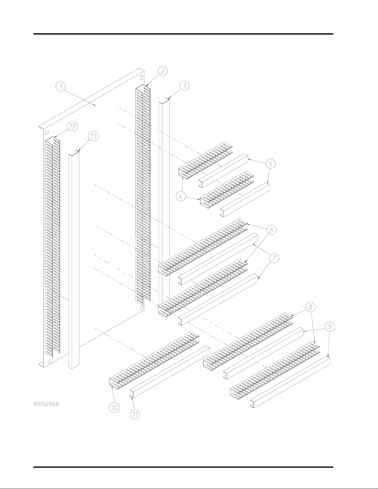
Right Hand Electrical Panel Wireway Channels
American Dryer Corporation 88 Currant Road / Fall River, MA 02720-4781
Page 21

Right Hand Electrical Panel W ireway Channels
Illus. No. Part No. Qty Description
1 334611 1 Right Hand Electrical Panel ONLY
2 121429 28 2" Deep x 1" Wide Wireway*
3 121422 28 1" Wireway Cover*
4 121429 8 2" Deep x 1" Wide Wireway*
5 121422 8 1" Wireway Cover*
6 121429 12 2" Deep x 1" Wide Wireway*
7 121422 12 1" Wireway Cover*
8 121429 12 2" Deep x 1" Wide Wireway*
9 121422 12 1" Wireway Cover*
10 121429 12 2" Deep x 1" Wide Wireway*
11 121422 12 1" Wireway Cover*
12 121429 31 2" Deep x 1" Wide Wireway*
13 121422 31 1" Wireway Cover*
* Sold by the inch
19
Telephone: (508) 678-9010 Fax: (508) 678-9447
Page 22
American Dryer Corporation 88 Currant Road / Fall River, MA 02720-4781
20
Top of Right Hand Electrical Panel
For models mfd. as of August 26, 1997
Page 23

Top of Right Hand Electrical Panel
For models mfd. as of August 26, 1997
Illus. No. Part No. Qty Description
1* 132444 1 3HP 110V Control Relay
2 120721 3 Fused Disconnect Terminal Block (for 380, 460, 575V ONLY)
4 Fused Disconnect Terminal Block (for 2808, 240V ONLY)
3 120997 1 20 Amp Fused Disconnect Terminal Block
4 120999 4 Blank Marking Tag (for 380, 460, 575V ONLY)
120999 5 Blank Marking Tag (for 208, 240V ONLY)
5 136031 2 7 Amp Fast Acting Fuse (for 208 volt models)
182453 2 6 Amp Fast Acting Fuse (for 230/240 volt models)
6 136056 1 20 Amp Slo-Blo Fuse (for 208/230/240 volt models)
7 136057 2 0.5 Amp Slo-Blo Fuse (for 208/230/240 volt models)
8 136056 1 20 Amp Slo-Blo Fuse (for 380/416/460/575 volt models)
9 136057 1 0.5 Amp Slo-Blo Fuse (for 380/416/460/575 volt models)
10 182453 2 6 Amp Fast Acting Fuse (for 380/416 volt models)
136030 2 5 Amp Fast Acting Fuse (for 460/480 volt models)
136052 2 4 Amp Fast Acting Fuse (for 575/600 volt models)
11 120761 2 Four Position Terminal Block
12 120752 2 Disconnect Block
13 120998 6 Bus Bar Screw
14 120990 3 2 Pole Bus Bar
15 120750 1 Ground Terminal Block
16 120766 1 End Plate
17 120752 2 Disconnect Block
18 120766 1 End Plate
19 120752 2 Disconnect Block
20 120766 1 End Plate
21 120750 2 Ground Terminal Block
22 150309 4 10-16 x 1/2" Hex Head Crimptite Screw
23 120765 1 End Stop
24 120768 - DIN Mounting Rail (Sold by the inch)
25 150108 4 8-32 x 1/2" Phillips Crimptite Screw
26 153000 4 #8 Flat Washer
27 152005 4 3/8-16 Hex Nut
28 153005 4 3/8" Lock Washer
29 153004 4 3/8" Flat Washer
30 132087 1 Control Transformer 300VA (for 208/240 volt models)
132088 1 Control Transformer 450VA (for 380/416 volt models)
132089 1 Control Transformer 450VA (for 460/480/575 volt models)
31 150106 2 8-32 x 1" Phillips Head Machine Screw
32 120730 1 30 Position A, B, C Block
33 123223 1 Mini Flasher, 24 VAC
34 153000 1 #8 Flat Washer
35 131408 9 DPDT Socket
36 150103 9 8-32 x 3/4" Phillips Head Machine Screw
37 131407 9 DPDT Relay
38 131409 9 Hold Down
21
* For models with sprinkler option
Telephone: (508) 678-9010 Fax: (508) 678-9447
Page 24

22
Top of Right Hand Electrical Panel
For models mfd. prior to August 26, 1997
Illus. No. Part No. Qty Description
1 120765 1 End Stop
2 120721 4 Fused Disconnect Terminal Block (for 380, 460, 575 volts ONLY)
5 Fused Disconnect Terminal Block (for 208, 240 volts ONLY)
3 120999 4 Blank Marking Tag (for 380, 460, 575 volts ONLY)
120999 5 Blank Marking Tag (for 208, 240 volts ONLY)
4 * --------- 1 Fuse (for 208, 240 volts ONLY)
5 * --------- 1 Fuse (for 208, 240 volts ONLY)
6 * --------- 1 Fuse (for 208, 240 volts ONLY)
7 * --------- 1 Fuse (for 208, 240 volts ONLY)
8 * --------- 1 Fuse (for 208, 240 volts ONLY)
American Dryer Corporation 88 Currant Road / Fall River, MA 02720-4781
Page 25

Top of Right Hand Electrical Panel
For models mfd. prior to August 26, 1997
Illus. No. Part No. Qty Description
9 * --------- 1 Fuse (for 380 volts ONLY)
1 Fuse (for 480 volts ONLY)
1 Fuse (for 575 volts ONLY)
10* --------- 1 Fuse (for 380 volts ONLY)
1 Fuse (for 480 volts ONLY)
1 Fuse (for 575 volts ONLY)
11* --------- 1 Fuse (for 380, 460, 575 volts ONLY)
12* --------- 1 Fuse (for 380, 460, 575 volts ONLY)
13 120761 2 Four Position Terminal Block
14 120752 2 Disconnect Block
15 120998 6 Bus Bar Screw
16 120990 3 2 Pole Bus Bar
17 120750 1 Ground Terminal Block
18 120766 1 End Plate
19 120752 2 Disconnect Block
20 120766 1 End Plate
21 120752 2 Disconnect Block
22 120766 1 End Plate
23 120750 2 Ground Terminal Block
24 150309 4 10-16 x 1/2" Hex Head Crimptite Screw
25 120768 - DIN Mounting Rail (Sold by the inch)
26 150108 4 8-32 x 1/2" Phillips Crimptite Screw
27 153000 4 #8 Flat Washer
28 152005 4 3/8-16 Hex Nut
29 153005 4 3/8" Lock Washer
30 153004 4 3/8" Flat Washer
31* 881854 1 208V 300VA Control Transformer Kit
881855 1 240V 300VA Control Transformer Kit
881856 1 380/416V 450VA Control Transformer Kit
881857 1 460/480V 450VA Control Transformer Kit
32 150106 2 8-32 x 1" Phillips Head Machine Screw
33 120730 1 30 Position A, B, C Block
34 123223 1 Mini Flasher, 24 VAC
35 153000 1 #8 Flat Washer
36 131408 9 DPDT Socket
37 150103 9 8-32 x 3/4" Phillips Head Machine Screw
38 131407 9 DPDT Relay
39 131409 9 Hold Down
40** 132444 1 3HP 110V Control Relay
23
* Control Transformer Kits include new fuses.
Fuses
cannot be ordered separate.
* *For models with sprinkler option.
Telephone: (508) 678-9010 Fax: (508) 678-9447
Page 26

American Dryer Corporation 88 Currant Road / Fall River, MA 02720-4781
24
Bottom of Right Hand Electrical Panel
Page 27

Bottom of Right Hand Electrical Panel
Illus. No. Part No. Qty Description
1 120768 - DIN Mounting Rail (Sold by the inch)
2 120765 1 End Stop
3 150309 4 10-16 x 1/2" Hex Head Crimptite Screw
4 137913 1 Micro One Expansion Computer
5 137914 1 Computer Interface Cable
6* 881029 1 Micro One Computer (Programmed)
7 120765 1 End Stop
8 120768 - DIN Mounting Rail (Sold by the inch)
9 150309 4 10-16 x 1/2" Hex Head Crimptite Screw
10 120765 1 End Stop
11 120766 1 End Plate
12 120758 9 Single Input Block
13 120761 1 Four Position Block
14 120758 4 Single Input Block
15 120761 1 Four Position Block
16 120758 14 Single Input Block
17 120761 2 Four Position Block
18 120758 13 Single Input Block
19 120761 3 Four Position Block
20 120758 3 Single Input Block
21 120999 16 Blank Marking Tag
22 120761 4 Four Position Block
23 120765 1 End Stop
24 120766 1 End Plate
25 120758 5 Single Input Block
26 120761 3 Four Position Block
27 120750 1 Ground Terminal Block
28 120758 3 Single Input Block
29 120750 1 Ground Terminal Block
30 120758 6 Single Input Block
31 120765 1 End Stop
32 150309 4 10-16 x 1/2" Hex Head Crimptite Screw
33 120765 1 End Stop
34 120768 - Din Mounting Rail (Sold by the inch)
35 131408 3 DPDT Socket
36 150103 4 8-32 x 3/4" Phillips Head Machine Screw
37 131407 3 DPDT Relay
38 131409 3 Hold Down
25
* Dryer serial number must be provided.
Telephone: (508) 678-9010 Fax: (508) 678-9447
Page 28

26
All Door, All T ilt, Base Electrical Junction Box Contr ol Panel Assembly
Illus. No. Part No. Qty Description
1 153004 4 3/8" Flat Washer
2 153005 4 3/8" Lock Washer
3 152005 4 3/8-16 Hex Nut
4 120768 - Din Mounting Rail (Sold by the inch)
5 131956 1 56-80 Amp Manual Starter (Blower Motor)
(for 208/230 volt models)
131957 1 25-40 Amp Manual Starter (Blower Motor)
(for 380/416/460/575 volt models)
American Dryer Corporation 88 Currant Road / Fall River, MA 02720-4781
Page 29

All Door, All T ilt, Base Electrical Junction Box Contr ol Panel Assembly
Illus. No. Part No. Qty Description
6 132384 1 Auxiliary Contact Block
7 150300 3 #10 x 1/2" Hex Washer TEK Screw
8 120765 1 End Stop
9 131957 1 25-40 Amp Manual Starter (Drive Motor)
(for 208 volt models)
131969 1 20-25 Amp Manual Starter (Drive Motor)
(for 230 volt models)
131970 1 9-14 Amp Manual Starter (Drive Motor)
(for 380/416/460 volt models)
131962 1 6-10 Amp Manual Starter (Drive Motor)
(for 575 volt models)
10 132384 1 Auxiliary Contact Block
(for 208 volt models)
132389 1 Auxiliary Contact Block
(for 230/380/416/460/575 volt models)
11* 136052 2 4 Amp Fuse
12 136038 2 8 Amp Fast-Acting Fuse
13 120724 2or4 Blank Marking Tags
14 120721 2 Fused Disconnect Terminal Block
15* 120721 2 Fused Disconnect Terminal Block
16 132423 1 Reversing Contactor
(for 208/230 volt models)
132424 1 Reversing Contactor
(for 380/416/460/575 volt models)
17 132437 2 24-48 Volt Varistor
18 132485 1 24 Volt Spike Suppressor
19 132479 1 Blower Contactor
(for 208/230 volt models)
132481 1 Blower Contactor
(for 380/416/460/575 volt models)
20 122424 1 Small Power Warning Label
21 120768 - DIN Mounting Rail (sold by the inch)
22 150300 5 #10 x 1/2" Hex Head TEK Screw
23 120763 1 End Holder
24 120762 3 Terminal Block
25 120763 1 End Holder
26 120750 1 Ground Terminal Block
27* 120758 2 Feed Thru Terminal Block
28* 120750 1 Ground Terminal Block
29 112075 1 "Ground Here" Label
30 152002 1 1/4-20 Hex Nut
31 153007 1 1/4" Lock Washer
32 121012 2 Terminal Lug
27
Telephone: (508) 678-9010 Fax: (508) 678-9447
Page 30

28
Drive Motor Assembly
For models mfd. as of November 14, 1997
Illus. No. Part No. Qty Description
1 101152 1 SH x 1-3/8" Bushing
2 101187 1 2B x 3.6 Sheave (60 Hz Models)
101195 1 2B x 4.4 Sheave (50 Hz Models)
3 100143 2 A 29 Belt
4 100704 1 1/4" x 1/4" x 1-3/4" Key
5 181023 1 7-1/2 HP 50/60 Hz Drive Motor
6 153004 4 3/8" Flat Washer
7 153005 4 3/8" Lock Washer
8 150508 4 3/8-16 x 3/4" Hex Head Bolt
American Dryer Corporation 88 Currant Road / Fall River, MA 02720-4781
Page 31

Drive Motor Assembly
For models mfd. prior to November 14, 1997
29
Illus. No. Part No. Qty Description
1 814066 1 Motor Adjustment Plate ONLY
2 334595 2 Motor Threaded Block
3 150609 2 1/2-13 x 4-1/2" Long Hex Head Bolt
4 814065 2 Motor Adjustment Bracket
5 153026 2 1/2" Lock Washer
6 152011 2 1/2-13 Hex Nut
7 153005 4 3/8" Lock Washer
8 150617 4 3/8-16 x 1" Long Hex Head Bolt
9 101299 1 Double Sprocket
10 101212 1 Bushing 1-5/8" Dia. Bore
11 181017 1 7-1/2 HP, 1200 RPM Motor
12 153026 4 1/2" Lock Washer
13 150633 4 1/2-13 x 2-1/4" Long Hex Head Bolt
Telephone: (508) 678-9010 Fax: (508) 678-9447
Page 32

30
Drive Shaft Assembly
For models mfd. as of November 14, 1997
Illus. No. Part No. Qty Description
1 820600 2 Drive Wheel Assembly
2 101191 2 RI x 2" Taper Lock Bushing
3 100234 2 2" Pillow Block Bearing
4 153016 4 5/8" Flat Washer
5 150627 4 5/8-11 x 5" Hex Head Bolt
6 101022 1 2" Taper Bushing for Speed Reducer
7 153016 4 5/8" Flat Washer
8 153015 4 5/8" Lock Washer
9 152010 4 5/8-11 Hex Nut
10 101019 1 Taper Bushed Speed Reducer
11 101176 1 2B x 5.6 Sheave
12 100709 1 3/8" x 3/8" x 2" Key
13 101196 1 SDS x 1-5/8" Bushing
14 331548 1 2" x 64-11/16" Drive Shaft
15 150629 2 1/2-13 x 3-1/2" Hex Head Bolt
16 153026 2 1/2" Lock Washer
17 152011 2 1/2-13 Hex Nut
American Dryer Corporation 88 Currant Road / Fall River, MA 02720-4781
Page 33

Drive Shaft Assembly
For models mfd. prior to November 14, 1997
31
Illus. No. Part No. Qty Description
1 101191 2 Wheel Taper Lock Bushing
2 820600 2 Drive Wheel Assembly with Hub
3 100712 1 1/2" x 1/2" x 3" Long Key
4 100234 2 Pillow Block Bearing
5 150627 4 5/8-11 x 5" Long Bolt
6 153016 4 5/8" Flat Washer
7 153016 4 5/8" Flat Washer
8 153015 4 5/8" Lock Washer
9 152010 4 5/8-11 Hex Nut
10 334577 1 Drive Shaft
11 100712 1 1/2" x 1/2" x 3" Long Key
12 100712 1 1/2" x 1/2" x 3" Long Key
13 101210 1 Bushing
14 101297 1 Sprocket
15 150629 2 1/2-13 x 3-1/2" Long Full Thread Bolt
16 153026 2 1/2" Lock Washer
17 152011 2 1/2-13 Hex Nut
Telephone: (508) 678-9010 Fax: (508) 678-9447
Page 34

32
Speed Reducing Idler Shaft Assembly
For models mfd. prior to November 14, 1997
American Dryer Corporation 88 Currant Road / Fall River, MA 02720-4781
Page 35

Speed Reducing Idler Shaft Assembly
For models mfd. prior to November 14, 1997
Illus. No. Part No. Qty Description
1 152011 4 1/2-13 Hex Nut
2 153026 4 1/2" Lock Washer
3 153011 4 1/2" Flat Washer
4 150606 4 1/2-13 x 2" Long Hex Head Bolt
5 153026 4 1/2" Lock Washer
6 153011 4 1/2" Flat Washer
7 150606 4 1/2-13 x 2" Long Hex Head Bolt
8 153026 4 1/2" Lock Washer
9 153011 4 1/2" Flat Washer
10 814067 1 Idler Mount ONLY
11 152011 2 1/2-13 Hex Nut
12 153026 2 1/2" Lock Washer
13 150609 2 1/2-13 x 4-1/2" Long Hex Head Bolt
14 101211 1 Bushing 1-3/4" Dia. Bore
15 101298 1 Sprocket
16 100710 1 3/8" x 3/8" x 3" Long Key
17 334597 2 Bearing Spacer Block
18 100239 2 1-3/4" Dia. Pillow Block Bearing
19 100816 2 1-3/4" E-Clip
20 153011 4 1/2" Flat Washer
21 150629 4 1/2-13 x 3-1/2" Long Hex Head Bolt
22 154322 4 3/8-24 x 7/16" Long Set Screw
23 334598 1 Speed Reducing Idler Shaft
24 100710 1 3/8" x 3/8" x 3" Long Key
25 101296 1 Sprocket
26 101154 1 Bushing
33
Telephone: (508) 678-9010 Fax: (508) 678-9447
Page 36

34
Tumbler and Idler Shaft Assembly
Illus. No. Part No. Qty Description
1 881399 1 Tumbler
2 820600 2 Drive Wheel Assembly
3 101191 2 Wheel Taper Lock Bushing
4 170511 2 1/8-27 N.P.T. Grease Fitting
5 150627 4 5/8-11 x 5" Long Bolt
6 153016 4 5/8" Flat Washer
7 880882 2 " Pillow Block Bearing
8 152011 2 1/2-13 Hex Nut
9 153026 2 1/2" Lock Washer
10 150629 2 1/2-13 x 3-1/2" Long Full Thread Bolt
11 153016 4 5/8" Flat Washer
12 153015 4 5/8" Lock Washer
13 152010 4 5/8-11 Hex Nut
14 334578 1 Idler Shaft
15 100712 2 1/2" x 1/2" x 3" Long Key
American Dryer Corporation 88 Currant Road / Fall River, MA 02720-4781
Page 37

Rotational Sensor Assembly Diagram
35
Illus. No. Part No. Qty Description
1 102102 1 Tumbler Sensor Magnet
2 154200 1 5/32" Pop Rivet
3 332750 1 Rotational Sensor Mounting Bracket
4 881383 1 Rotational Sensor Assembly
5 881384 1 Rotational Sensor Harness
Telephone: (508) 678-9010 Fax: (508) 678-9447
Page 38

36
Fan Motor Assembly
American Dryer Corporation 88 Currant Road / Fall River, MA 02720-4781
Page 39

Fan Motor Assembly
Illus. No. Part No. Qty Description
1 152053 2 3/4-16 Left Hand Jam Nut
2 153071 1 2-3/4" O.D. Fan Washer
3 100661 1 22-1/4" Dia. Blower Wheel
4 100710 1 3/8" x 3/8" x 3" Long Key
5 334445 1 Shaft
6 814005 1 Motor Mount ONLY
7 153004 6 3/8" Flat Washer
8 153005 6 3/8" Lock Washer
9 150617 6 3/8-16 x 1" Long Hex Head Bolt
10 100239 2 1-3/4" Dia. Bearing
11 150606 4 1/2-13 x 2" Long Hex Head Bolt
12 153026 4 1/2" Lock Washer
13 153011 4 1/2" Flat Washer
14 116014 1 Felt Seal
15 100710 1 3/8" x 3/8" x 3" Long Key
16 100172 2 BX-66 V-Belt (Gas Models ONLY)
100179 2 BX-75 V-Belt (Steam Models ONLY)
17 101165 1 2B 18.4 Pulley
18 101154 1 SK x 1-3/4 Bushing Models
19 101196 1 SDS x 1-5/8 Bushing
20 101202 1 2B 5.2 Pulley (60 Hz Gas Models ONLY)
101185 1 2B 6.2 Pulley (50 Hz Gas Models ONLY)
101175 1 2B 6.8 Pulley (Steam Models ONLY)
21 152011 4 1/2-13 Hex Nut
22 153011 4 1/2" Flat Washer
23 181006 1 25 HP 3600 RPM Motor
24 150606 4 1/2-13 x 2" Long Hex Bolt
25 153026 4 1/2" Lock Washer
26 154322 4 3/8-24 x 7/16" Long Set Screw
27 814074 1 Fan Motor Adjustment Angle
28 152011 4 1/2-13 Hex Nut
29 334635 1 Fan Motor Adjustment Block
30 153026 2 1/2" Lock Washer
31 150630 2 1/2-13 x 6" Hex Head Bolt
32 150618 2 1/2-13 x 1" Hex Head Bolt
33 100816 2 1-3/4" Dia. Retaining Clip (Used on models mfd. prior to 11-18-96)
37
Telephone: (508) 678-9010 Fax: (508) 678-9447
Page 40

38
T emperatur e Sensor Bracket
Illus. No. Part No. Qty Description
1 814008 1 Sensor Bracket Assembly
814009 1 Sensor Bracket Assembly Complete
(includes illus. nos. 1 through 10)
2 150000 2 #6-32 x 1/4" Slotted Round Head Machine Screw
3 153010 2 #6 Star Washer
4 130112 1 L-225 Thermostat
5 152000 3 #6-32 Hex Nut
6 121028 2 1/4" x .032 Insulated Terminal
7 122701 4 Sockets
8 122605 1 4 Pin Socket Connector (Female)
9 154007 2 1/4" Push-On Fastener
10 880251 1 1/4" Temperature Sensor Probe Assembly
(includes illus. nos. 6 through 10)
11 150301 4 #8-18 x 7/16" Phillips Pan Head TEK Screw
American Dryer Corporation 88 Currant Road / Fall River, MA 02720-4781
Page 41

DSI Module Assembly
39
Illus. No. Part No. Qty Description
1 880815 1 DSI Module 50/60 Hz
2 820100 1 DSI Module Mount Assembly ONLY
3 121400 2 Universal Bushing
4 150522 3 1/4-20 x 1/2" Self Tapping Hex Head Machine Screw
5 150301 1 #8-18 x 7/16" Phillips Pan Head TEK Screw
6 153010 4 #6 Star Washer
7 152000 4 #6-32 Hex Nut
Telephone: (508) 678-9010 Fax: (508) 678-9447
Page 42

40
Front Burner Box Assembly
American Dryer Corporation 88 Currant Road / Fall River, MA 02720-4781
Page 43

Front Burner Box Assembly
Illus. No. Part No. Qty Description
1 150301 4 #8-18 x 7/16" Phillips Pan Head TEK Screw
2 334086 1 Manifold Rest
3 141110 5 Burner Tube
4 150301 10 #8-18 x 7/16" Phillips Pan Head TEK Screw
5 150301 4 #8-18 x 7/16" Phillips Pan Head TEK Screw
6 334083 1 Front Burner Tube Rest
7 150301 5 #8-18 x 7/16" Phillips Pan Head TEK Screw
8 150301 5 #8-18 x 7/16" Phillips Pan Head TEK Screw
9 331290 1 Sight Hole Disk
10 332597 1 Burner Box Cover Plate
1 1 --------- 1 Sail Switch Assembly See Page: 44
12 150309 2 #10-16 x 1/2" Hex Head Crimptite Screw
13 880325 1 Ignitor/Flame Probe Assembly Kit
14 150001 2 #6-32 x 1/2" Round Head Machine Screw
15 130401 1 L-330 Hi-Limit
16 151000 2 #6-32 Pal Nut
17 881395 1 Front Burner Box ONLY
18 881144 1 Hi-Limit Mounting Bracket
19 150301 4 #8-18 x 7/16 Phillips Pan Head TEK Screw
20 332826 1 Burner Baffle
21 150301 4 #8-18 x 7/16" Phillips Pan Head TEK Screw
41
Telephone: (508) 678-9010 Fax: (508) 678-9447
Page 44

42
Rear Burner Box Assembly
American Dryer Corporation 88 Currant Road / Fall River, MA 02720-4781
Page 45

Rear Burner Box Assembly
Illus. No. Part No. Qty Description
1 150301 4 #8-18 x 7/16" Phillips Pan Head TEK Screw
2 334086 1 Manifold Rest
3 141110 5 Burner Tube
4 150301 10 #8-18 x 7/16" Phillips Pan Head TEK Screw
5 150301 4 #8-18 x 7/16" Phillips Pan Head TEK Screw
6 334084 1 Rear Burner Tube Rest
7 150301 5 #8-18 x 7/16" Phillips Pan Head TEK Screw
8 150301 1 #8-18 x 7/16" Phillips Pan Head TEK Screw
9 331290 1 Sight Hole Disk
10 332597 1 Burner Box Cover Plate
1 1 --------- 1 Sail Switch Assembly See Page: 44
12 150309 2 #10-16 x 1/2" Hex Head Crimptite Screw
13 880325 1 Ignitor/Flame Probe Assembly Kit
14 150001 2 #6-32 x 1/2" Round Head Machine Screw
15 130401 1 L-330 Hi-Limit
16 151000 2 #6-32 Pal Nut
17 881394 1 Rear Burner Box ONLY
18 881144 1 Hi-Limit Mounting Bracket
19 150301 4 #8-18 x 7/16 Phillips Pan Head TEK Screw
20 332826 1 Burner Baffle
21 150301 4 #8-18 x 7/16" Phillips Pan Head TEK Screw
43
Telephone: (508) 678-9010 Fax: (508) 678-9447
Page 46

44
Sail Switch Assembly
Illus. No. Part No. Qty Description
1 105500 1 Sail Switch Actuator Rod
2 332689 1 Sail Switch Damper
3 154002 1 1/8" Push On Fastener
4 802800 1 Sail Switch Box with Cover and Bracket ONLY (items 4, 8, and 9)
881376 1 Sail Switch Box Assembly Complete
(includes illus. nos. 1 through 4 and 6 through 10)
5 150300 2 #10 x 1/2" Hex Washer Head TEK Screw
6 150303 2 #4 x 3/4" Pan Head Machine Screw
7 122404 1 Sail Switch
8 802799 1 Sail Switch Box Cover and Bracket ONLY
9 150309 2 #10-16 x 1/2" Hex Head Crimptite Screw
10 154004 1 Twin Speed Nut
American Dryer Corporation 88 Currant Road / Fall River, MA 02720-4781
Page 47

Air Jet Assembly
45
Illus. No. Part No. Qty Description
1 332531 2 Air Jet Mounting Plate
2 153007 4 1/4" Lock Washer
3 152002 4 1/4-20 Hex Nut
4 143277 2 1/4" Comp. x 1/8" M.P.T. Connector
5 143100 3 1/4" Aluminum Tubing (Sold by the foot)
6 143271 1 1/4" Comp. Union Tee
7 143259 2 Bulkhead Fitting, 1/4" Comp. x 1/8" F.P.T.
8 143277 1 1/4" Comp. x 1/8" M.P.T. 90 Degree Brass Elbow
9 150309 2 10-16 x 1/2" Hex Head Crimptite Screw
10 100520 1 1/8" Muffler
11 150002 2 #6-32 x 1" Phillips Round Head Machine Screw
12 100498 1 3 Way Valve
13 100472 1 1/4" Poly x 1/8" M.P.T. Connector
14 153010 2 #6 Star Washer
15 152000 2 #6-32 Hex Nut
Telephone: (508) 678-9010 Fax: (508) 678-9447
Page 48

46
Gas Piping Assembly
American Dryer Corporation 88 Currant Road / Fall River, MA 02720-4781
Page 49

Gas Piping Assembly
Illus. No. Part No. Qty Description
1 142931 1 2" x 1-1/2" Double Tapped Bushing
2 150504 4 5/16-18 x 1" Long Hex Nut
3 142514 1 2" Floor Flange
4 153002 4 5/16" Lock Washer
5 152004 4 5/16-18 Hex Nut
6 142569 1 1-1/2" x 18" Long Nipple
7 142611 1 1-1/2" x 1-1/4" x 1-1/4" Tee
8 142725 1 1-1/4" x 2" Long Nipple
9 142725 1 1-1/4" x 2" Long Nipple
10 142554 1 1-1/4" x 90º
11 142725 1 1-1/4" x 2" Long Nipple
12 141416 2 1-1/4" x 48" Flex Hose
13 142558 1 1-1/4" Union
14 142558 1 1-1/4" Union
15 142554 1 1-1/4" x 90º Elbow
16 142725 1 1-1/4" x 2" Long Elbow
17 142611 1 1-1/2" x 1-1/4" x 1-1/4" Tee
18 142573 1 1-1/2" x 10" Long Nipple
19 142512 1 1-1/2" x 90º Elbow
20 142736 1 1-1/2" x 20" Long Nipple
21 142512 1 1-1/2" x 90º Elbow
22 142596 1 1-1/2" x 5" Long Nipple
23 142603 1 1-1/2" Union
24 150522 4 TEK Screw
25 814063 1 Gas Pipe Bracket
26 142596 1 1-1/2" x 5" Long Nipple
27 142915 1 1-1/2" x 45º Elbow
28 142738 1 1-1/2" x 2" Long Nipple
29 142915 1 1-1/2" x 45º Elbow
30 150510 8 1/4-20 x 3/4" Long Hex Head Bolt
31 153007 8 1/4" Lock Washer
32 142736 1 1-1/2" x 20" Long Nipple
33 142512 1 1-1/2" x 90º Elbow
34 334602 4 Bottom Gas Pipe Bracket
35 142736 1 1-1/2" x 20" Long Nipple
36 142512 1 1-1/2" x 90º Elbow
37 332828 1 Pipe Bracket
38 150522 2 TEL Screw
39 154351 6 1-1/2" Pipe U-Bolt
40 142808 1 1" x 3" Long Nipple
41 142603 1 1-1/2" Union
42 142573 1 1-1/2" x 10" Long Nipple
43 142841 1 1-1/4" x 1-1/4" x 1-1/2" T ee
44 142599 2 1-1/4" x 22" Long Nipple
45 142558 2 1-1/4" Union
46 142725 2 1-1/4" x 2" Long Nipple
Elbow
47
Continued on next page.
Telephone: (508) 678-9010 Fax: (508) 678-9447
Page 50

48
Illus. No. Part No. Qty Description
47 142554 2 1-1/4" x 90º Elbow
48 142575 2 1-1/4" x 18" Long Nipple
49 142728 2 1" to 1-1/4" Reducing Elbow
50 142844 2 1" x 45º Male Elbow
51 141302 2 1" Shut-Off
52 142808 2 1" x 3" Long Nipple
53 142602 2 1" Union
54 142711 2 1" Close Nipple
55 140017 2 1" 2 4V Gas Valve (Natural Gas)
140018 2 L.P. Gas Valve Conversion Kit
56 142724 2 1" x 2" Long Nipple
57 142548 2 1" x 90º Elbow
58 141242 1 Rear Manifold, 5 Port
59 141241 1 Front Manifold, 5 Port
60 140840 10 #1 Burner Orifice (natural gas) ONLY
140821 10 #28 Burner Orifice (liquid propane gas) ONLY
881425 1 ADG-410 L.P. Conversion Kit
Gas Piping Assembly
American Dryer Corporation 88 Currant Road / Fall River, MA 02720-4781
Page 51

T ilt Switch Assembly
49
Illus. No. Part No. Qty Description
1 881252 1 Tilt Switch Assembly Complete
(includes illus. nos. 1, 2, and 4)
122365 1 Limit Switch Rotary Head ONLY
2 122369 1 Tilt Switch Arm
3 150211 4 10-32 x 2" Phillips Pan Head Machine Screw
4 122367 1 Tilt Switch Body
5 153009 4 #10 Star Washer
6 152008 4 #10-32 Hex Nut
7 150309 4 #10-16 x 1/2" Hex Head Crimptite Screw
8 332794 1 Tilt Switch Bracket
NOTE: One assembly for one-way tilt models.
Two assemblies for two-way tilt models.
Telephone: (508) 678-9010 Fax: (508) 678-9447
Page 52

50
Tilt Piston Mount Assembly
Illus. No. Part No. Qty Description
1 100562 1 Piston (5" Bore, 15" Stroke)
2 143283 1 3/8" Poly x 3/8" M.P.T. Straight Connector
3 143221 1 3/8" Poly Tee, Brass
4 143120 20 3/8" Poly Tubing (Sold by the foot)
5 143213 1 3/8" Poly x 3/8" M.P.T. Elbow, Brass
6 334309 2 Cylinder Pin Nylon Bumper
7 150435 4 3/8-16 x 3" Socket Head Cap Screw
8 100553 1 Rod Eye
9 154315 2 1/2-20 x 1-1/8" Socket Head Set Screw
10 331543 1 1" Dia. Pin
11 150599 4 1/4-20 x 1-1/4" Hex Head Machine Bolt
12 153026 4 1/2" Lock Washer
13 153011 4 9/16" I.D. Flat Washer
14 881170 1 Clevis Assembly
American Dryer Corporation 88 Currant Road / Fall River, MA 02720-4781
Page 53

Post Assembly
51
Illus. No. Part No. Qty Description
1 100487 1 3/4" Diameter Pin with Cotter Pin
2 881529 1 Post Assembly
3 100553 1 Rod Eye
4 154315 2 1/4-20 x 1" Socket Head Set Screw
5 334309 2 Nylon Bumper
6 150435 4 3/8-16 x 3" Socket Head Cap Screw
7 331543 1 1" Diameter Pin
8 150599 4 1/2-20 x 1-1/8" Hex Head Bolt
9 153026 4 1/2" Lock Washer
10 881170 1 Clevis Assembly
Telephone: (508) 678-9010 Fax: (508) 678-9447
Page 54

52
Pneumatic Assembly
For 1 Automatic Door
Illus. No. Part No. Qty Description
1 152000 2 #6-32 Hex Nut
2 153010 2 #6 Star Washer
3 330987 1 Valve Mounting Bracket
4 150522 2 1/4-20 x 1/2" Hex Head TEK Screw
5 143289 1 1/4" Poly x 1/8" M.P.T. Connector
6 100498 1 3 Way Valve
7 150002 2 #6-32 x 1" Phillips Round Head Machine Screw
8 100520 1 1/8" Muffler
9 143239 1 1/8" 2-1/2" Brass Nipple
10 100520 1 1/8" Muffler
11 100468 1 4 Way Valve, 24 Volt
12 143289 2 1/4" Poly x 1/8" M.P.T. Connector
13 143115 38 1/4" Poly Flo Tubing (sold by the foot)
14 150008 2 #6-32 x 1-1/4" Right Hand Machine Screw
15 814349 1 AD-410 Solenoid Interface Junction Box
16 120703 1 6 Position Screw Connector
17 152000 2 #6-32 Hex Nut
18 120915 2 1/2" N.P.T. Lock Nut
19 120914 2 1/2" N.P.T. Metal Clad Sealing Washer
20 120656 1 Straight Brown Cord Grip Connector
21 120653 1 Straight White Cord Grip Connector
American Dryer Corporation 88 Currant Road / Fall River, MA 02720-4781
Page 55

Pneumatic Assembly
For 2 Automatic Doors
53
Illus. No. Part No. Qty Description
1 143115 - 1/4" Poly Flow Tubing (Sold by the foot)
2 143289 2 1/4" Poly x 1/8" MPT Connector
3 100468 1 4-Way Value 24 Volt
4 100520 1 1/8" Muffler
5 143268 1 1/8" Brass Street Elbow
6 143238 1 1/8" Close Nipple
7 100520 1 1/8" Muffler
8 143268 1 1/8" Brass Street Elbow
9 143238 1 1/8" Close Nipple
10 143237 1 1/8" Brass Cross
11 143238 1 1/8" Close Nipple
12 143250 1 1/8" Brass Plug
13 100468 1 4-Way Valve 24 Volt
14 143289 2 1/4" Poly x 1/8" MPT Connector
15 143115 - 1/4" Poly Flow Tubing (Sold by the foot)
16 150002 2 #6-32 x 1" Phillips Round Head Machine Screw
17 100520 1 1/8" Muffler
18 100498 1 3-Way Valve 24 Volt
19 143115 - 1/4" Poly Flow Tubing
20 143289 1 1/4" Poly x 1/8" MPT Connector
21 150522 2 1/4-20 x 1/2" Hex Head TEK Screw
22 330987 1 Valve Mounting Bracket
23 153010 2 #6 Star Washer
24 152000 2 #6-32 Hex Nut
Telephone: (508) 678-9010 Fax: (508) 678-9447
Page 56

54
Pneumatic Panel Assembly
For One-W ay Tilt Models
American Dryer Corporation 88 Currant Road / Fall River, MA 02720-4781
Page 57

Pneumatic Panel Assembly
For One-W ay Tilt Models
Illus. No. Part No. Qty Description
1 814011 1 Pneumatic Plate ONLY
2 100479 1 3/8" Filter/Regulator Gauge
(for models mfd. as of July 14, 1997)
100516 1 Filter/Regulator/Lubricator Gauge
(for models mfd. prior to July 14, 1997)
3 150512 4 1/4-20 x 1/2" Hex Head Bolt
4 153007 6 1/4" Lock Washer
5 100558 1 5 Port, 3 Position, 24 VAC Tilting Solenoid
6 100462 2 3/8" Muffler
7 143283 5 3/8" Poly x 3/8" MPT Straight Connector
8 143120 - 3/8" Poly Flo Tubing (Sold by the foot)
9 143241 1 3/8" Close Nipple
10 143206 2 3/8" Flow Control
11 153018 4 1/4" Flat Washer
12 143115 - 1/4" Poly Flo Tubing (Sold by the foot)
13 143290 1 1/4" Poly x 3/8" MPT Brass Elbow
14 150524 2 1/4-20 x 2" Hex Head Bolt
15 150522 6 1/4-20 x 1/2" Hex Head TEK Screw
16 143213 4 3/8" Poly x 3/8" MPT Brass Elbow
17 332841 1 Air Flow Valve Plate
18 143220 1 3/8" Brass Tee
19 332624 1 Filter/Regulator Adapter Bracket
55
Telephone: (508) 678-9010 Fax: (508) 678-9447
Page 58

56
Pneumatic Panel Assembly
For T wo-Way T ilt Models
American Dryer Corporation 88 Currant Road / Fall River, MA 02720-4781
Page 59

Pneumatic Panel Assembly
For T wo-W ay Tilt Models
Illus. No. Part No. Qty Description
1 814011 1 Pneumatic Plate ONLY
2 100479 1 3/8" Filter/Regulator Gauge
(for models mfd. as of July 14, 1997)
100516 1 Filter/Regulator/Lubricator Gauge
(for models mfd. prior to July 14, 1997)
3 150512 6 1/4-20 x 1/2" Hex Head Bolt
4 153007 10 1/4" Lock Washer
5 143220 1 3/8" Brass Tee
6 100558 2 Tilting Solenoid, 24 VAC, 5 Port, 3 Position
100569 - 24 VAC Coil ONLY
7 100462 4 3/8" Muffler
8 143283 10 3/8" Poly x 3/8" MPT Brass Straight Connector
9 143120 8 3/8" Poly Flo Tubing (Sold by the foot)
10 143241 1 3/8" Close Nipple
11 143206 4 3/8" Flow Control
12 153018 8 1/4" Flat Washer
13 143115 14 1/4" Poly Flo Hi-Temp Tubing (Sold by the foot)
14 143290 1 1/4" Poly x 3/8" MPT Brass Elbow
15 150524 4 1/4-20 x 2" Long Bolt
16 150522 6 1/4-20 x 1/2" Hex Washer Head TEK Screw
17 143157 2 Reducing Poly Tee, 3/8" x 3/8" x 1/4"
18 143221 1 3/8" Poly Tee
19 143213 6 3/8" Poly x 3/8" MPT Brass Elbow
20 332841 2 Air Flow Valve Plate
21 143149 2 1/4" Poly x 1/8" MPT Elbow Connector
22 332624 1 3/8" Filter/Regulator Mounting Bracket
(for models mfd. as of July 14, 1997)
57
Telephone: (508) 678-9010 Fax: (508) 678-9447
Page 60

58
Optional Sprinkler Assembly
American Dryer Corporation 88 Currant Road / Fall River, MA 02720-4781
Page 61

Optional Sprinkler Assembly
Illus. No. Part No. Qty Description
1 881426 7 1/4" Hex Plug (1/4" Dia. Hole Drilled Through Center)
2 142926 7 1" x 1/4" Reducing Bushing
3 142548 1 1" x 90º Elbow
4 142579 6 1" x 6" Long Nipple
5 142508 6 1" Tee
6 142724 1 1" x 2" Long Nipple
7 142548 1 1" x 90º Elbow
8 142585 1 1" x 18" Long Nipple
9 142590 1 1" x 45º Elbow
10 142808 1 1" x 3" Long Nipple
11 142590 1 1" x 45º Elbow
12 142746 1 1" x 24" Long Nipple
13 142602 1 1" Union
14 142589 1 1" x 10" Long Nipple
15 142548 1 1" x 90º Elbow
16 142579 1 1" x 6" Long Nipple
17 142548 1 1" x 90º Elbow
18 142587 1 1" x 27-1/2" Long Nipple
19 142602 1 1" Union
20 143136 1 1" Dia. Hose Nipple
21 143210 1 1/4" Comp. x 1/4" MPT Brass Elbow
22 100565 1 1" Water Valve (for models mfd. as of September 9, 1996)
881414 1 1" Water Valve (for models mfd. prior to September 9, 1996)
23 142808 1 1" x 3" Long Nipple
24 142548 1 1" x 90º Elbow
25 143136 1 1" Dia. Hose Nipple
26 143135 1 4' Long Flex Hose
27 142584 1 1" x 4-1/2" Long Nipple
28 142548 1 1" x 90º Elbow
29 142808 1 1" x 3" Long Nipple
30 143556 1 1" Ball Valve
31 143100 12 1/4" Aluminum Tubing (Sold by the foot)
32 150415 2 Crimptite Screw
33 814063 1 Lower Sprinkler Bracket
34 154350 6 1" Pipe U-Bolt
35 334255 1 1" Pipe Bracket
36 150522 2 1/4-20 x 1/2" TEK Screw
37 334610 2 Inner Sprinkler Pipe Bracket
38 150522 4 1/4-20 x 1/2" TEK Screw
39 334631 1 Sprinkler Bracket
40 331794 1 Inlet Pipe Bracket
41 143137 2 Hose Clamp
42 150522 2 1/4-20 x 1/2" TEK Screw
43 150522 4 1/4-20 x 1/2" TEK Screw
44 150522 8 1/4-20 x 1/2" TEK Screw
59
Telephone: (508) 678-9010 Fax: (508) 678-9447
Page 62

60
Sprinkler Temperature Probe Junction Box Assembly
American Dryer Corporation 88 Currant Road / Fall River, MA 02720-4781
Page 63

Sprinkler Temperature Pr obe Junction Box Assembly
Illus. No. Part No. Qty Description
1 331877 1 Temperature Sensor Mounting Plate
2 150523 2 1/4-20 x 3/4" Hex Head TEK Screw
3 881227 1 RTD Temperature Probe Assembly
(includes illus. nos. 3, 4, and 8)
4 143296 1 1/4" Compression Fitting
5 120652 1 1/2" NPT Cord Grip (Red)
6 120915 1 1/2" NPT Locknut
7 120914 1 1/4" Metal Clad "O" Ring
8 122736 3 Yellow Ferrule
9 881228 1 Sprinkler Temperature Probe Box Assembly
(includes illus. nos. 9 and 12)
10 152000 2 6-32 Hex Nut
11 120703 1 6 Position Terminal Block
12 122427 1 Caution Label
13 150008 2 6-32 x 1-1/4" Phillips Head Machine Screw
14 122736 3 Yellow Ferrule
15 120914 1 1/2" Metal Clad "O" Ring
16 120915 1 1/2" NPT Locknut
17 120650 1 90º Cord Grip (White)
18 881229 1 Sprinkler Temperature Probe Harness
61
Telephone: (508) 678-9010 Fax: (508) 678-9447
Page 64

62
Steam Coil Assembly
American Dryer Corporation 88 Currant Road / Fall River, MA 02720-4781
Page 65

Steam Coil Assembly
Illus. No. Part No. Qty Description
1 165034 1 Steam Coil Assembly
2 150523 8 1/4-20 x 3/4" Hex Head TEK Screw
3 153007 4 1/4" Lock Washer
4 152002 4 1/4-20 Hex Nut
5 820321 2 Steam Damper Hinge Assembly
6 115995 144 Steam Damper Gasket (sold by the inch)
7 881661 1 Steam Damper Assembly
(includes illus. nos. 6 through 8)
8 102350 2 Steam Damper Foam
9 153007 4 1/4" Lock Washer
10 152002 4 1/4-20 Hex Nut
11 151008 1 5/8-18 S.S. Acorn Nut
12 152030 1 5/8-18 Jam Nut
13 100525 1 2" Bore, 4" Stroke Piston
14 152002 4 1/4-20 Hex Nut
15 153007 4 1/4" Lock Washer
16 100526 1 Piston Pivot Bracket
17 143238 1 1/8" Brass Close Nipple
18 143264 1 1/4" Poly x 1/8" Brass Reducing Bushing
19 100496 1 1/8" Needle Valve
20 100472 1 1/4" Poly x 1/8" MPT Connector
21 143115 -- 1/4" O.D. Tubing (sold by the foot)
22 143156 1 1/4" Poly Tee
23 143115 -- 1/4" O.D. Tubing (sold by the foot)
24 100472 1 1/4" Poly x 1/8" MPT Connector
25 100496 1 1/8" Needle Valve
26 143264 1 1/4" Poly x 1/8" Brass Reducing Bushing
27 143238 1 1/8" Brass Close Nipple
28 100525 1 2" Bore, 4" Stroke Piston
29 151008 1 5/8-18 S.S. Acorn Nut
30 153030 1 5/8-18 Jam Nut
31 152002 4 1/4-20 Hex Nut
32 153007 4 1/4" Lock Washer
33 100526 1 Piston Pivot Bracket
34 152002 2 1/4-20 Hex Nut
35 153007 2 1/4" Lock Washer
36 153010 2 #6 Star Washer
37 152000 2 6-32 Hex Nut
38 330987 1 Micro Valve Support
39 100472 1 1/4" Poly x 1/8" MPT Connector
40 100472 1 1/4" Poly x 1/8" MPT Connector
41 143115 -- 1/4" O.D. Tubing (sold by the foot)
42 100498 1 3-Way Micro Valve - 24 VAC
43 150002 2 6/32 x 1" Phillips Head Machine Screw
44 100520 1 1/8" N.P.T Silencer
63
Telephone: (508) 678-9010 Fax: (508) 678-9447
Page 66

64
Sprinkler Solenoid Assembly
Illus. No. Part No. Qty Description
1 100556 1 Sprinkler Solenoid 120 Volt
2 153018 4 1/4" Flat Washer
3 100462 1 3/8" Valve Muffler
4 143283 1 3/8" Poly x 3/8" MPT Brass Connector
5 143120 6 3/8" Poly Flow Tubing (sold by the foot)
6 143151 1 1/4" Compression to 3/8" MPT Brass Elbow
7 153007 2 1/4" Lock Washer
8 150524 2 1/4-20 x 2" Hex Head Machine Bolt
9 143100 12 1/4" Aluminum Tubing (sold by the foot)
10 150309 2 #10-16 x 1/2" Hex Head Crimptite Screw
11 154005 2 1/4" Tube Clip
12 143221 1 3/8" Poly Tee
American Dryer Corporation 88 Currant Road / Fall River, MA 02720-4781
Page 67

T umbler Retaining Wheel Mount Assembly
65
Illus. No. Part No. Qty Description
1 152005 2 3/8-16 Hex Nut
2 153005 2 3/8" Lock Washer
3 820566 2 Retaining Wheel Assembly
4 153062 4 Spherical Washer
5 153004 2 3/8" Flat Washer
6 150438 2 3/8-16 x 3-1/4" Long Bolt
Telephone: (508) 678-9010 Fax: (508) 678-9447
Page 68

66
Guard Assemblies
For T wo-Way T ilt Models
American Dryer Corporation 88 Currant Road / Fall River, MA 02720-4781
Page 69

Guard Assemblies
For T wo-W ay Tilt Models
Illus. No. Part No. Qty Description
1* 881396 1 Front Guard Door ONLY
2 150300 4 #10 x 1/2" Hex Head TEK Screw
3 170607 1 Door Magnet
4* 881397 1 Front Guard Assembly Complete
(includes illus. nos. 1 through 6)
5 170348 2 Front Tilt Guard Glide
6 150412 4 3/4" Long Crimptite Screw
7* 334538 1 Side Shield Assembly
8 150512 6 1/4-20 x 1/2" Long Hex Head Bolt
9 153007 6 1/4" Lock Washer
10* 334538 1 Side Shield Assembly
11 150512 6 1/4-20 x 1/2" Long Hex Head Bolt
12 153007 6 1/4" Lock Washer
13 151004 4 1/4-20 Hex Nut
14 153007 6 1/4" Lock Washer
15 821628 2 Spring Catch
16 157014 2 Spring #125
17 108121 2 15" Long Chain
18 154354 2 3/4" Pipe U-Bolt
19* 881398 1 Rear Guard Assembly Complete
(includes illus. nos. 13 through 21)
20 150412 8 Crimptite Screw, 3/4" Long
21 170345 4 Rear Tilt Nylon Glide
67
* Specify color when ordering
Telephone: (508) 678-9010 Fax: (508) 678-9447
Page 70

68
Side Panel Assemblies
American Dryer Corporation 88 Currant Road / Fall River, MA 02720-4781
Page 71

Side Panel Assemblies
Illus. No. Part No. Qty Description
1 150522 16 1/4-20 x 1/2" TEK Screw
2* 814032 1 Top Left Panel
3* 814033 1 Bottom Hinged Door Assembly
4 150522 18 1/4-20 x 1/2" TEK Screw
5* 334538 1 Side Shield Assembly
6 150512 6 1/4-20 x 1/2" Long Hex Head Bolt
7 153007 6 1/4" Lock Washer
8* 334600 1 Left Side Rear Base Panel
9 150522 4 1/4-20 x 1/2" TEK Screw
10 150522 10 1/4-20 x 1/2" TEK Screw
11* 814088 1 Left Base Panel Assembly
12 150522 2 1/4-20 x 1/2" TEK Screw
13* 334601 1 Left Side Front Base Panel
14 150522 16 1/4-20 x 1/2" TEK Screw
15* 814031 1 Top Right Panel Assembly (60 Hz ONLY)
16 150522 18 1/4-20 x 1/2" TEK Screw
17* 814033 1 Bottom Hinged Door Assembly
18* 334538 1 Side Shield Assembly
19 153007 6 1/4" Lock Washer
20 150512 6 1/4-20 x 1/2" Long Hex Head Bolt
21 150522 6 1/4-20 x 1/2" Long TEK Screw
22* 334544 1 Right Side Base Panel
23 150522 6 1/4-20x 1/2" Long TEK Screw
24* 334545 1 Gas Inlet Base Panel
25 150522 6 1/4-20 x 1/2" TEK Screw
26* 334544 1 Right Side Base Panel
27 150522 16 1/4-20 x 1/2" Long TEK Screw
28 814031 1 Top Right Panel Assembly (Steam Machines ONLY)
69
* Specify color when ordering
Telephone: (508) 678-9010 Fax: (508) 678-9447
Page 72

70
Front Base & Front Top Panel Assemblies
Illus. No. Part No. Qty Description
1* 334542 2 Piston Cover
2 150415 12 Crimptite Sheet Metal Screw
3* 334671 2 Right Front Base Panel
4 150522 12 1/4-20 x 1/2" TEK Screw
5 332681 2 Right Gusset for Top Front Panel
6 150522 9 1/4-20 x 1/2" TEK Screw
7* 334546 1 Top Front Panel
8* 332680 1 Left Gusset for Top Front Panel
9 150522 7 1/4-20 x 1/2" TEK Screw
10 150522 9 1/4-20 x 1/2" TEK Screw
* Specify color when ordering
American Dryer Corporation 88 Currant Road / Fall River, MA 02720-4781
Page 73

End of Cycle Light Assembly
71
Illus. No. Part No. Qty Description
1 151001 2 #8-32 Pal Nut
2 150309 4 #10-16 x 1/2" Hex Head Crimptite Screw
3 150108 2 #8-32 x 1/2" Phillips Head Machine Screw
4* 821480 1 Cycle Light Bracket (for Steam Models ONLY)
5 152001 4 #8-32 Hex Nut
6 153012 4 #8 Star Washer
7* 332850 1 Cycle Light Bracket (for Gas Models ONLY)
8 150108 2 #8-32 x 1/2" Phillips Head Machine Screw
9 123222 1 "Orange" Cycle Light
10 123221 1 24 VAC Bulb
11 151001 2 #8-32 Pal Nut
12 150108 4 #8-32 x 1/2" Phillips Head Machine Screw
* Specify color when ordering.
Telephone: (508) 678-9010 Fax: (508) 678-9447
Page 74

American Dryer Corporation 88 Currant Road / Fall River, MA 02720-4781
72
trahCesaBgnitnuoMdna,etalpemaN,hctiwSrotceleS
tliTyaW-2htiwsledoM
srooDcitamotuA/launaM
31.oN.sullI
rotceleS
hctiwS
41.oN.sullI
etalpemaN
73.oN.sullI
dna
83.oN.sullI
gnitnuoM
esaB
CDA 843221.oNtraP
CDA 214221.oNtraP
rotceleSmaCnoitisoP-3
hctiwS
”daolnU-yrD-daoL“
hctiwSrotceleShtiwdedulcnI
CDA 063221.oNtraP
CDA 224221.oNtraP
CDA 793231.oNtraP
esaB
tliTdwFhtiwsledoM
srooDlaunaM
CDA 843221.oNtraP
hctiwSnoitisoP-2
CDA 214221.oNtraP
”1-0“daolnU
htiwkcolBtcatnoCCN-ON
hctiwS
hctiwS
tliTdwFhtiwsledoM
srooDcitamotuA
CDA 843221.oNtraP
rotceleSmaCnoitisoP-3
hctiwS
CDA 534221.oNtraP
”daolnU-yrD-daoL“
rotceleShtiwdedulcnI
tliTraeRhtiwsledoM
srooDcitamotuA/launaM
rotceleSmaCnoitisoP-3
”detliT-ffO-leveL“daoL
Selector Switch, Nameplate, and Mounting Base Chart
hctiwSrotceleShtiwdedulcnI
Page 75

ADC 450166 1- 09/05/96-50 2* 03/05/98-50
 Loading...