

Page 1
AD-78 II
Parts Manual
2001-2002
American Dryer Corporation
88 Currant Road
Fall River, MA 02720-4781
T elephone: (508) 678-9000 / Fax: (508) 678-9447
E-mail: techsupport@amdry.com
www .amdry .com
ADC Part No. 450576
Page 2

Retain This Manual In A Safe Place For Future Reference
American Dryer Corporation products embody advanced concepts in engineering, design, and safety. If this product is
properly maintained, it will provide many years of safe, efficient, and trouble-free operation.
ONLY qualified technicians should service this equipment.
OBSERVE ALL SAFETY PRECAUTIONS displayed on the equipment or specified in the installation manual included with
the dryer.
The following “FOR YOUR SAFETY” caution must be posted near the dryer in a prominent location.
FOR YOUR SAFETY
Do not store or use gasoline or
other flammable vapors and
liquids in the vicinity of this or
any other appliance.
W e have tried to make this manual as complete as possible and hope you will find it useful. ADC reserves the right to make
changes from time to time, without notice or obligation, in prices, specifications, colors, and material, and to change or
discontinue models.
POUR VOTRE SÉCURITÉ
Ne pas entreposer ni utiliser d’essence
ni d’autres vapeurs ou liquides
inflammables à proximité de cet
appareil ou de tout autre appareil.
Important
For your convenience, log the following information:
DATE OF PURCHASE ____________________________ MODEL NO. __________________________________________
RESELLER’S NAME _______________________________________________________________________________________
Serial Number(s) ________________________________________________________________________________________
________________________________________________________________________________________
AD-78 II
________________________________________________________________________________________
Replacement parts can be obtained from your reseller or the ADC factory. When ordering replacement parts from the factory ,
you can F AX your order to ADC at (508) 678-9447 or telephone your order directly to the ADC Parts Department at (508)
678-9000. Please specify the dryer model number and serial number in addition to the description and part number, so that
your order is processed accurately and promptly.
The illustrations on the following pages may not depict your particular dryer exactly. The illustrations are a composite of the
various dryer models. Be sure to check the descriptions of the parts thoroughly before ordering.
“IMPORT ANT NOTE TO PURCHASER”
Information must be obtained from your local gas supplier on the instructions
to be followed if the user smells gas. These instructions must be posted in a
prominent location near the dryer .
Page 3

Table of Contents
OPL Control Door Assembly.................................................................................................................. 2
Control Door (Coin Models) .................................................................................................................. 3
Phase 5 OPL Microprocessor Control Panel Assembly ........................................................................... 4
Phase 5 Coin Microprocessor Control Panel Assembly ........................................................................... 5
Coin V ault Assembly............................................................................................................................... 6
Front Panel Assembly ............................................................................................................................. 7
Main Door Assembly (Round Door) ....................................................................................................... 8
Main Door Switch Assembly For Round Main Door ............................................................................... 9
Sensor Bracket Assembly ..................................................................................................................... 10
Lint Trap Assembly ............................................................................................................................... 11
Drop Lint Door Assembly..................................................................................................................... 12
Basket (Tumbler) Support Assembly ..................................................................................................... 13
Idler Bearing Assembly ......................................................................................................................... 14
Basket (Tumbler) Bearing Assembly...................................................................................................... 15
Single-Phase (1ø) Motor, Electric Relay Panel Assembly ....................................................................... 16
3-Phase (3ø) Motor, Non-Reversing Electric Relay Panel Assembly ...................................................... 17
3-Phase (3ø) Motor, Reversing Electric Relay Panel Assembly ........................................................ 18, 19
Non-Reversing T .E.F .C. Motor Mount Assembly ............................................................................ 20, 21
Reversing T .E.F .C. Motor Mount Assembly .................................................................................... 22, 23
Hot Surface Ignition (HSI) Burner Assembly
CE Export ................................................................................................................................... 24, 25
Direct Spark Ignition (DSI) Burner Assembley
For Models Mfd. as of April 11, 2000 ......................................................................................... 26, 27
Sail Switch Assembly............................................................................................................................ 28
Back Guard Assemblies ........................................................................................................................ 29
Microprocessor Coin Acceptors Listing ................................................................................................ 30
Additional Parts A vailable ..................................................................................................................... 31
Page 4
2
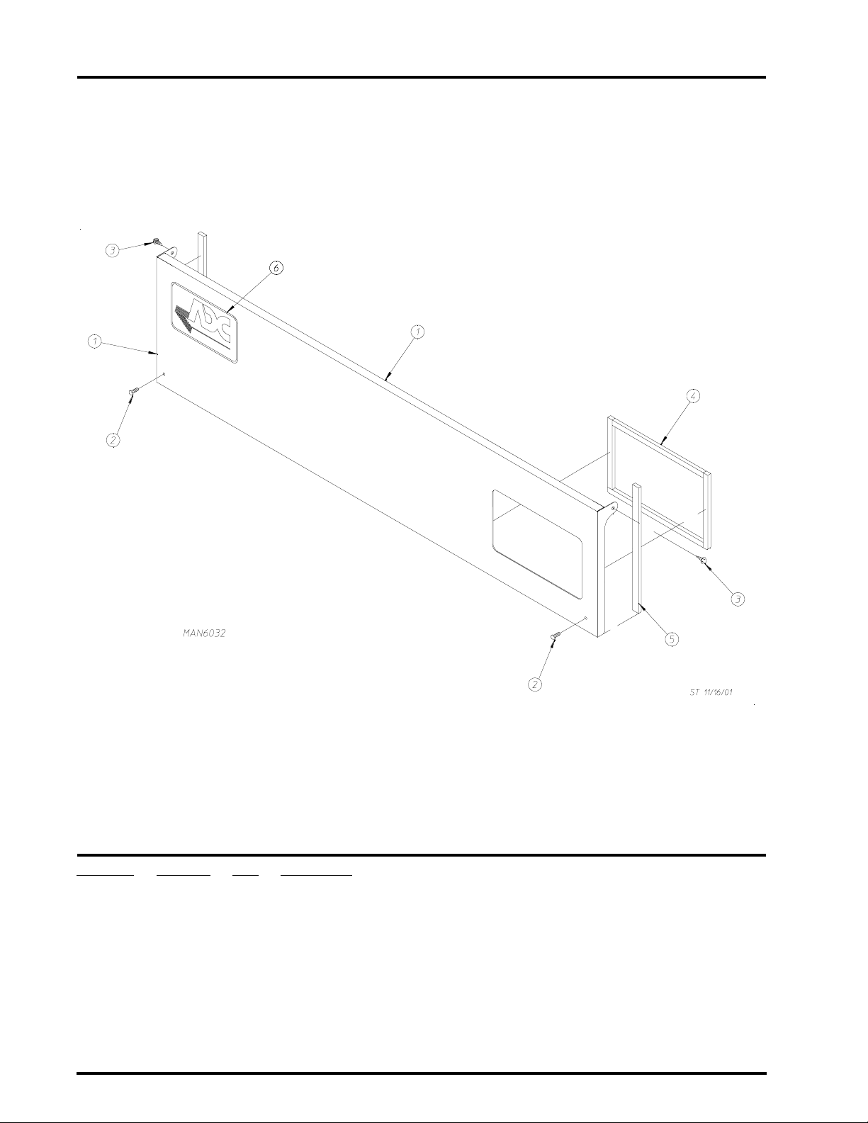
OPL Contr ol Door Assembly
Illus. No. Part No. Qty. Description
1 883244* 1 Control Door Assembly
(includes illus. nos. 1, 4, and 5)
2 150134 2 #10-32 x 1/2” TORX Screw
3 150317 2 #10-16 x 3/4” TORX Screw
4 117605 2 1/4” x 3/8” Neoprene Sponge Tape
5 117604 2 1/8” x 3/8” Neoprene Sponge Tape
6 881053 1 ADC Logo with Adhesive Tape
* Specify color when ordering.
American Dryer Corporation 88 Currant Road / Fall River, MA 02720-4781
Page 5
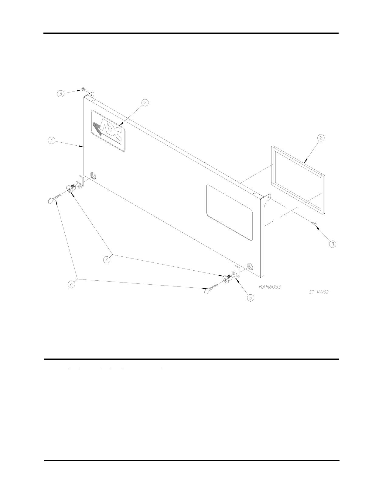
Control Door (Coin Models)
3
Illus. No. Part No. Qty. Description
1 883243** 1 Control Door without Locks
2 117605 2 1/4” x 3/8” Neoprene Sponge Tape
3 150317 2 #10-16 x 3/4” TORX Screw
4 160015 2 MK-100 Lock ONLY
5 160052 1 1” Ca m
6 160104 * MK-100 Key ONLY
7 881053 1 ADC Logo with Adhesive Tape
* As required.
** Specify color when ordering.
Telephone: (508) 678-9000 Fax: (508) 678-9447
Page 6
4
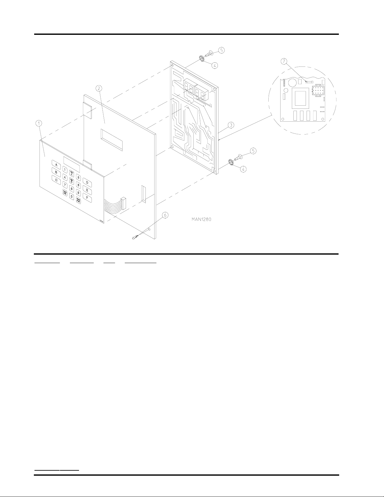
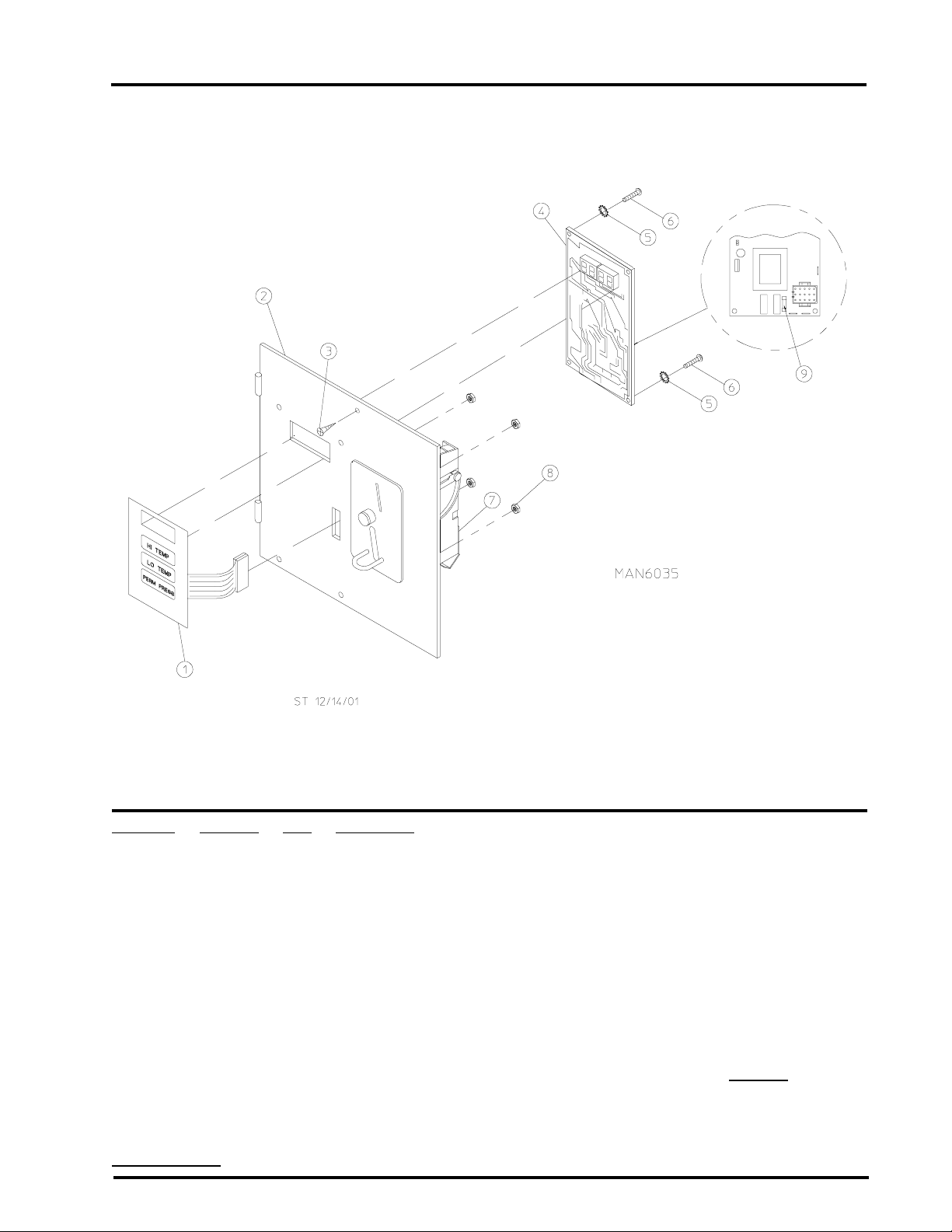
Phase 5 OPL Micr opr ocessor Control Panel Assembly
Illus. No. Part No. Qty. Description
1 112535 1 OPL English Keyboard (touch pad) Label Assembly
112276 1 OPL Stick-On Labels (English Only)...Not Illustrated
112275 1 3-Language OPL Stick-On Labels
(Spanish, Italian, and Hebrew)...Not Illustrated
112277 1 3-Language OPL Stick-On Labels
(English, Spanish, and Hebrew)...Not Illustrated
112278 1 5-Language OPL Stick-On Labels
(Italian, Dutch, French, German, and Chinese)...Not Illustrated
2 801255 1 Phase 5 Microprocessor Control Panel ONLY
801256 1 Phase 5 Microprocessor Control Panel ONLY with Battery Bracket
801206 1 Phase 5 OPL Non-Reversing Microprocessor Control Panel Assembly
Complete
(includes illus. nos. 1 through 6)
801207 1 Phase 5 OPL Reversing Microprocessor Control Panel Assembly Complete
(includes illus. nos. 1 through 6)
3 137222 1 Phase 5 OPL Non-Reversing Controller ONLY
137231 1 Phase 5 OPL Reversing Controller ONLY
824998 1 Phase 5 Battery Clip
4 153010 2 #6 S tar Washer
5 150005 2 #6-32 x 1/4” Phillips Round Head Machine Screw
6 150413 1 #10-16 x 1/2” TORX Head Crimptite Screw
7 136048 1 1/8-Amp (slo blo) Fuse
IMPORTANT : Check label on computer chip to verify correct part number for controller .
American Dryer Corporation 88 Currant Road / Fall River, MA 02720-4781
Page 7
Phase 5 Coin Micropr ocessor Contr ol Panel Assembly
5
Illus. No. Part No. Qty. Description
1 112526 1 Coin Keyboard (touch pad) Label Assembly
2 883254 1 Phase 5 Coin Control Panel Assembly
(includes illus. nos. 1, 2, 4, 5, and 6)
883253 1 Coin Control Panel ONLY
3 150309 1 #10-16 x 1/2” Hex Head TEK Crimptite Screw
4 137213 1 Phase 5 Coin Controller ONLY
824998 1 Phase 5 Battery Clip
5 153010 2 #6 S tar Washer
6 150005 2 #6-32 x 1/4” Phillips Round Head Machine Screw
7 -------- 1 Coin Acceptor
(refer to Microprocessor Coin Acceptors Listing on
8 152102 4 Hex Nut
9 136048 1 1/8-Amp (slo blo) Fuse
page 30)
IMPORTANT: Check label on computer chip to verify correct part number of controller.
Telephone: (508) 678-9000 Fax: (508) 678-9447
Page 8
6
Coin Vault Assembly
Illus. No. Part No. Qty. Description
1* 8801 18 1 Coin Box Assembly ONLY Less Lock
2** 160036 1 ACE® Lock Assembly with Key
3** 160136 1 ACE® Key ONLY
4 880117* 1 Coin Vault Assembly ONLY Less Lock
(includes illus. nos. 1, 4, and 5)
5 152014 4 1/4-20 Free Spin Wash Nut
* Specify color when ordering.
** Specify key number when ordering.
American Dryer Corporation 88 Currant Road / Fall River, MA 02720-4781
Page 9
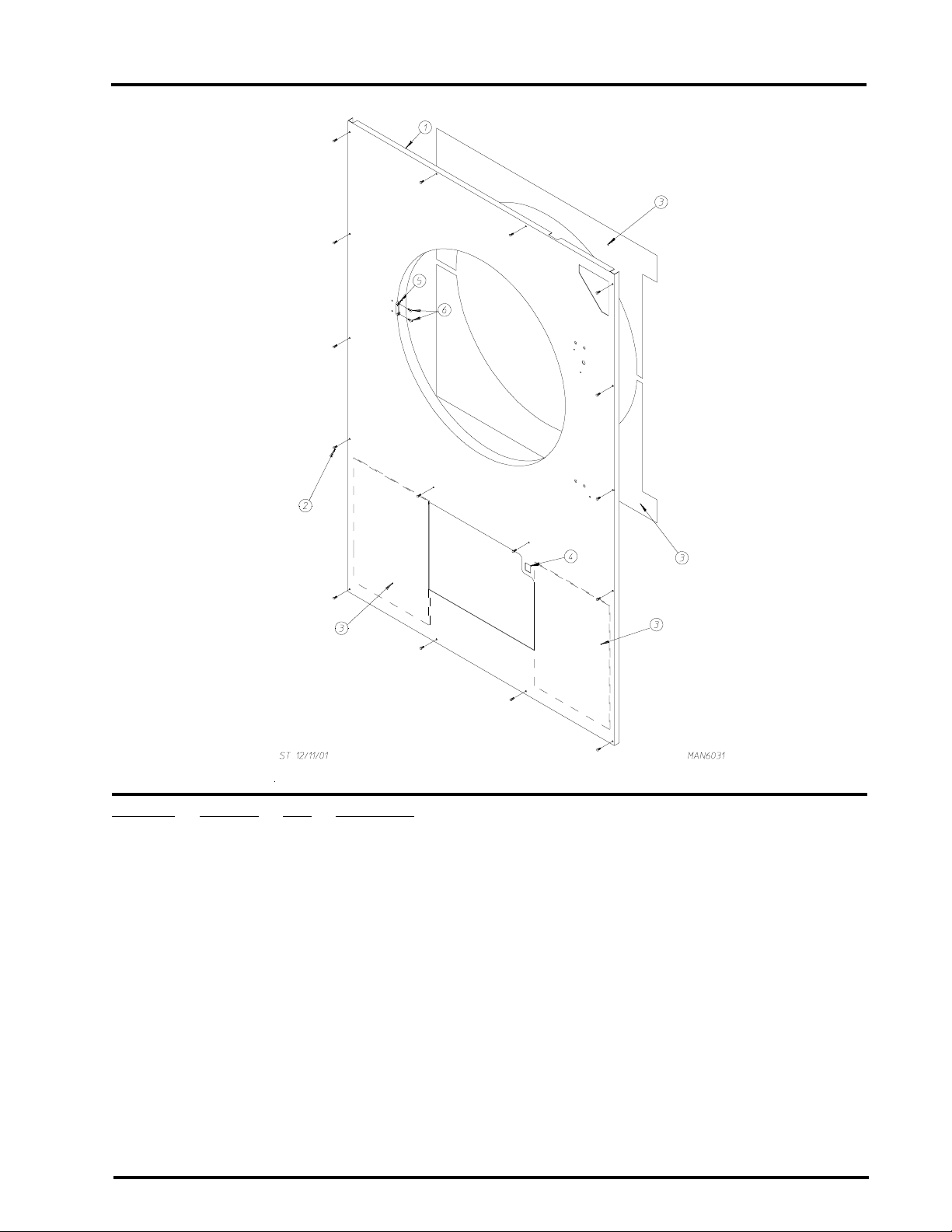
Front Panel Assembly
7
Illus. No. Part No. Qty. Description
1 883246* 1 Right Hand Front Panel Assembly (for OPL models)
(includes illus. nos. 1, 3, 5, and 6)
883245 1 Right Hand Front Panel Assembly (for coin models)
(includes illus. nos. 1, 3, 5, and 6)
2 150313 11 #10-16 x 1/2” TORX Plus BTN Type 1
150318 ** 25IP Stick-Fit TORX Plus Bit
3 116147 2 13 x 18-1/2” Rear Lower Wall Insulation
116320 1 Top Front Panel Insulation
116321 1 Bottom Front Panel Insulation
4 122002 1 Lint Drawer Switch
5 881987 1 Friction Door Latch Kit
(includes illus. nos. 5 and 6)
6 154215 2 5/32” Pop Rivet
* Specify color when ordering.
** As needed.
Telephone: (508) 678-9000 Fax: (508) 678-9447
Page 10
8
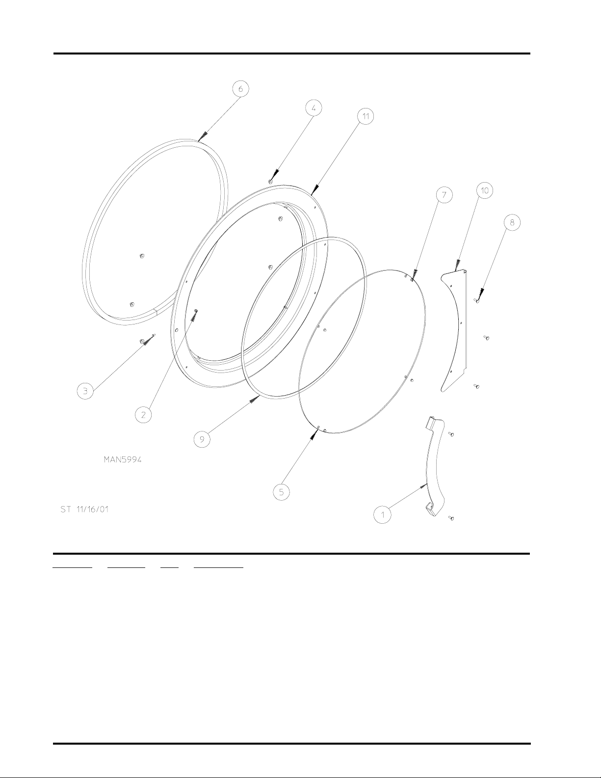
Main Door Assembly (Round Door)
Illus. No. Part No. Qty. Description
-- 883249 1 Black Main Door Assembly Complete
1 883252 1 Large Cold Rolled Steel (CRS) Black Main Door Handle
2 151010 1 #10-32 Black Hex Acorn Lock Nut
3 150120 1 #10-32 Door Latch Screw
4 152014 6 1/4-20 Free Spin Wash Nut
5 102214 1 30” Door Glass
6 102357 1 Large Steel Door Gasket
7 151013 4 #10-32 Black Acorn Nut
8 150683 6 1/4-20 x 5/8” Carriage Bolt
9 102361 1 Black Gasket Tape
10 883251 1 Large Black Main Door Hinge
11 883250 1 Large 37-1/4” Black Door Ring ONLY
American Dryer Corporation 88 Currant Road / Fall River, MA 02720-4781
Page 11
Main Door Switch Assembly For Round Main Door
9
Illus. No. Part No. Qty. Description
1 150006 2 #6-32 x 7/8” Phillips Pan Head Machine Screw
2 152013 2 #6-32 Hex Nut
3 153010 2 #6 S tar Washer
4 137005 1 Single-Pole Door Switch (SDS)
5 150443 4 1/4-20 x 3/4” Stainless Steel Cap Screw
6 882866 1 Black Main Door Switch Housing ONLY
88 1153 1 Black Main Door Switch with Housing Assembly
(includes illus. nos. 1 through 4 and 6)
7 150301 2 #8-18 x 7/16” Phillips Pan Head TEK Screw
8 8 8 1 1 5 1 1 Black Bottom Hinge Block
(includes illus. nos. 5 and 8)
9 8 81152 1 Black Top Hinge Block
(includes illus. nos. 5 and 9)
10 153031 1 Nylon W asher
Telephone: (508) 678-9000 Fax: (508) 678-9447
Page 12

10
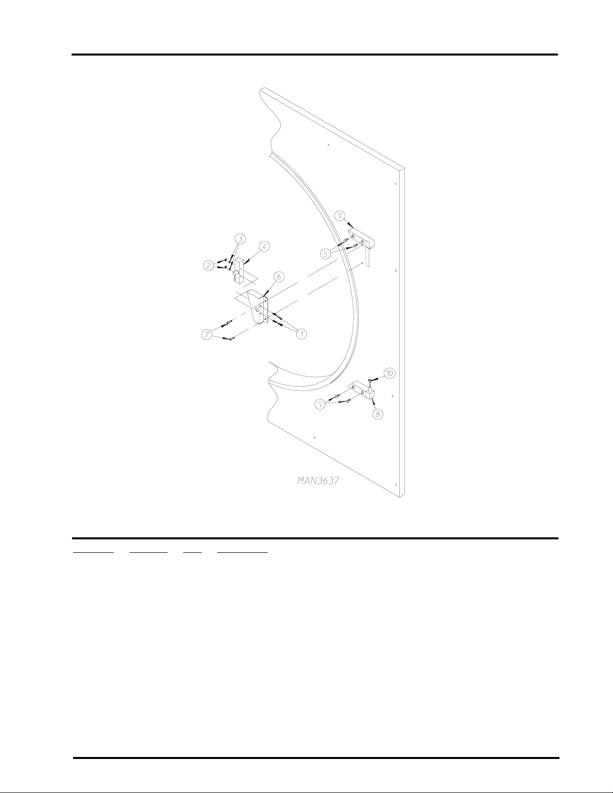
Sensor Bracket Assembly
Illus. No. Part No. Qty. Description
1 130103 1 225º F Large Automatic Thermostat ONLY
2 153010 2 #6 S tar Washer
3 152000 2 #6-32 Hex Nut
4 154007 2 1/4” Tinnerman Push On Fastener
5 150005 2 #6-32 x 1/4” Phillips Round Head Machine Screw
6 881912 1 Temperature Sensor Bracket Complete
(includes illus. nos. 1 through 7)
7 880251 1 1/4” Temperature Sensor Probe Assembly
(includes illus. nos. 7 through 9)
122605 1 4 Pin Socket Connector
8 122701 4 Socket T erminal ONLY
9 121028 2 Insulated T erminal ONLY
10 150301 2 #8-18 x 7/16” Phillips Pan Head TEK Screw
1 1 122604 1 4 Pin Connector ONLY
12 122700 4 Pin Terminal ONLY
122801 1 Pin/Socket Extraction T ool
(for removal of illus. nos. 8 and 12)
American Dryer Corporation 88 Currant Road / Fall River, MA 02720-4781
Page 13

Lint T rap Assembly
11
Illus. No. Part No. Qty. Description
1 881904 1 Lint Coupe Assembly Complete
(includes illus. nos. 1 and 3 through 5)
801767 1 Lint Coupe ONLY
2 154200 7 5/32” Pop Rivet
3 304100 1 Lint Screen Hold Down
4 150300 3 #10-16 x 1/2” Hex Washer TEK Screw
5 800500 2 Lint Screen
6 150419 2 #6 x 1/2” Tamperproof TEK Screw
7 108120 1 Chain for Drop Lint Door
150418 1 Tamperproof Screw Hand Driver
8 150425 2 #12-24 x 3/8” Phillips Round Head Screw
9 122116 1 Lint Drawer Switch ONLY
10 323724 1 Lint Drawer Switch Bracket
Telephone: (508) 678-9000 Fax: (508) 678-9447
Page 14

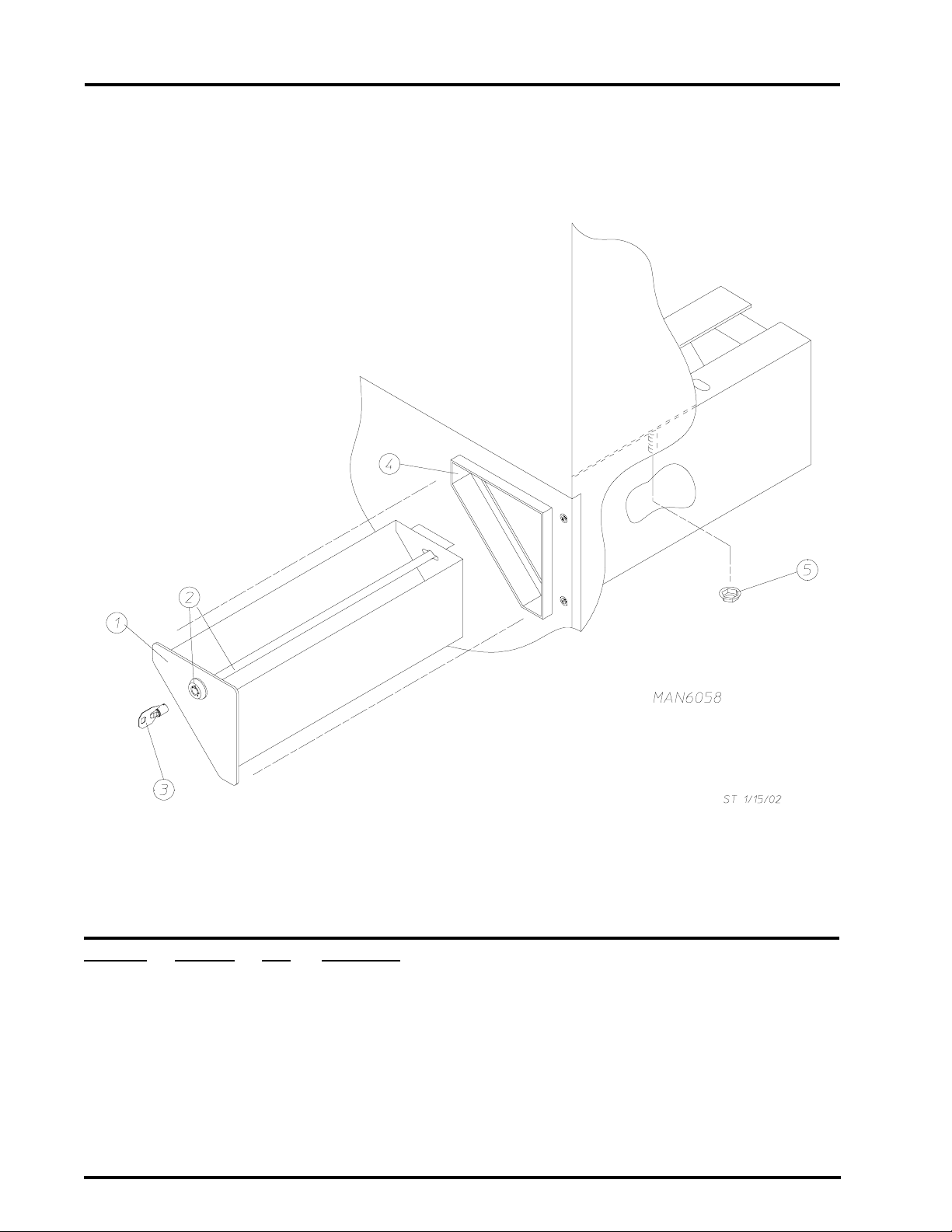
12
Drop Lint Door Assembly
Illus. No. Part No. Qty. Description
1 883248 1 Drop Lint Door (for OPL models)
883247 1 Drop Lint Door (for coin models)
2 117604 5 1/8” x 3/8” Neoprene Sponge Tape
3 170226 1 Slide Latch (for OPL models)
160001 1 Lint Door AD-100 Lock (for coin models)
160103 1 Key ONLY for AD-100 Lock
American Dryer Corporation 88 Currant Road / Fall River, MA 02720-4781
Page 15

Basket (T umbler) Support Assembly
13
Illus. No. Part No. Qty. Description
1 801751 1 Basket (tumbler) ONLY without Felt Collar
801773 1 Basket (tumbler) and Support Assembly Complete
(includes illus. nos. 1 through 11)
2 801774 1 Basket (tumbler) Support ONLY
3 150500 1 5/16-18 x 3/4” Socket Button Head Screw
4 100912 8 1/2-13 x 25-3/8” Tie Rod
5 116006 1 Felt Collar
170730 1 Felt Collar Adhesive (10.3 oz.)
6 153011 8 1/2” Flat Washer
7 153026 8 1/2” Lock Washer
8 152011 8 1/2-13 Hex Nut
9 301701 * Basket (tumbler) Shims
10 314701 4 Basket (tumbler) Ribs
11 150413 32 #10-16 x 1/2” TORX Crimptite Screws
* As required.
Telephone: (508) 678-9000 Fax: (508) 678-9447
Page 16

14
Idler Bearing Assembly
Illus. No. Part No. Qty. Description
1 100185 1 5L-780 V-Belt
2 1 0 1 1 4 0 1 14” x 3” Compound Pulley
3 100178 1 4L-570 V-Belt (idler to motor)
4 154301 2 5/16-18 x 1” Allen Setscrew
5 100705 1 3/16” x 3/16” x 1-3/8” Key
6 883473 1 Idler Bearing Assembly Complete
(includes illus. nos. 5 through 12)
7 150617 2 3/8-16 x 1” Hex Head Machine Bolt
8 153005 2 3/8” Lock Washer
9 153004 2 3/8” Flat Washer
10 801009 1 Idler Square Washer
11 152005 1 3/8”-16 Hex Nut
12 150623 1 3/8”-16 x 5” Hex Head Machine Bolt
American Dryer Corporation 88 Currant Road / Fall River, MA 02720-4781
Page 17

Basket (T umbler) Bearing Assembly
15
Illus. No. Part No. Qty. Description
1 100244 1 1-15/16” Flange Bearing
2 153025 4 Lock Washer
3 152050 4 Hex Nut
4 801775 1 Pillow Block Bearing Assembly Complete
(includes illus. nos. 4 through 13)
801761 1 Pillow Block Bearing Housing ONL Y
5 100245 1 1-15/16” Pillow Block Bearing
6 150633 2 1/2-13 x 2-1/4” Hex Head Bolt
7 153011 2 9/16” Flat Washer
8 153011 2 9/16” Flat Washer
9 153026 2 1/2” Lock Washer
10 152011 2 1/2-13 Hex Nut
11 154322 2 3/8-24 x 7/16 Setscrew
12 152004 2 5/16-18 Hex Nut
13 150621 2 5/16-18 x 1-1/2” Allen Setscrew
14 153002 4 5/16” Lock Washer
15 153001 6 5/16” Flat Washer
16 150621 4 5/16-18 x 3/4” Hex Bolt
17 314746 1 Rotational Sensor Bracket (option)
18 824807 1 Rotational Sensor Assembly (option)
19 150413 2 #10-16 x 1/2” Phillips Hex Head TEK Crimptite
20 101219 1 18” Pulley
88211 1 1 18” Pulley with Rotational Sensor Magnet (option)
21 101220 1 1-15/16” T aper Lock Bushing
22 100719 1 1/2” x 1/2” x 1-3/8” Key
23 100185 1 5L-780 V-Belt
24 152004 2 5/16-18 Hex Nut
25 150610 2 5/16-18 x 1-1/2” Allen Setscrew
26 102102 1 Rotational Sensor Magnet (option)
401010 1 Adhesive for Magnet
Telephone: (508) 678-9000 Fax: (508) 678-9447
Page 18

16
Single-Phase (1ø) Motor, Electric Relay Panel Assembly
Illus. No. Part No. Qty. Description
1 137015 1 RC Network
2 151000 2 #6-32 Pal Nut
3 150300 2 #10-16 x 1/2” Hex Washer TEK Screw
4 150008 2 #6-32 x 1-1/4” Phillips Round Head Machine Screw
5 120716 1 2-Position T erminal Block
6 306304 1 Electric Relay Panel Mounting Plate ONLY
7 132083 1 Step Down Transformer (for 120/240 volt 1Ø Only)
881763 1 Termination Kit
8 136008 * Fuse Holder ONLY
9 136049 1 3/4-Amp (slo blo) Fuse (for 120 volt models Only)
136057 2 1/2-Amp (slo blo) Fuse (for 208/240 volt Only)
10 150301 * #8-18 x 7/16” Phillips Pan Head TEK Screw
11 150297 1 #10 x 1/2” Green Hex Washer TEK Screw
12 152004 1 5/16-18 Hex Nut
13 121010 1 L-70 Ground Lug
14 153002 1 5/16” Lock Washer
15 132445 1 3-Pole Contactor - 24 VAC
16 121300 3 Open/Closed Bushing
* As required.
American Dryer Corporation 88 Currant Road / Fall River, MA 02720-4781
Page 19

3-Phase (3ø) Motor, Non-Reversing Electric Relay Panel Assembly
17
Illus. No. Part No. Qty. Description
1 150300 2 #10-16 x 1/2” Hex Washer TEK Screw
2 132083 1 Step Down Transformer (for 208/240 volts Only)
881763 Termination Kit
3 150301 2 #8-18 x 7/16” Phillips Pan Head TEK Screw
4 136008 2 Fuse Holder ONLY
5 136057 2 1/2-Amp (slo blo) Fuse
6 150297 1 #10 x 1/2” Green Hex Washer TEK Screw
7 121010 1 L-70 Ground Lug
8 153002 1 5/16” Lock Washer
9 152004 1 5/16-18 Hex Nut
10 137015 1 RC Network
11 132447 1 3-Pole Contactor - 24 VAC
12 322812 1 Electric Relay Panel Mounting Plate ONLY
13 150008 2 #6-32 x 1-1/4” Phillips Round Head Machine Screw
14 120701 1 4-Position T erminal Block
15 151000 2 #6-32 Pal Nut
16 121300 3 Open/Closed Bushing
Telephone: (508) 678-9000 Fax: (508) 678-9447
Page 20

18
3-Phase (3ø) Motor, Reversing Electric Relay Panel Assembly
American Dryer Corporation 88 Currant Road / Fall River, MA 02720-4781
Page 21

3-Phase (3ø) Motor, Reversing Electric Relay Panel Assembly
Illus. No. Part No. Qty. Description
1 150300 2 #10-16 x 1/2” Hex Washer TEK Screw
2 132083 1 Step Down Transformer
(for 208/230 volts Only)
881763 1 Termination Kit
3 137060 1 Arc Suppressor (A.S.) Board
4 137013 4 Nylon Standoff
5 132448 1 Reversing Contactor
(208/230/240/380/460 volt) 24 VAC
6 150301 2 #8-18 x 7/16” Phillips Pan Head TEK Screw
7 136008 2 Fuse Holder ONLY
(for 208-230/240 volt models Only)
8 136057 2 1/2-Amp (slo blo) Fuse
(for 208-230/240 volt models Only)
9 150297 1 #10 x 1/2” Green Hex Washer TEK Screw
10 121010 1 L-70 Ground Lug
11 153002 1 5/16” Lock Washer
12 152004 1 5/16-18 Hex Nut
13 132447 1 3-Pole Contactor - 24 VAC
14 150008 2 #6-32 x 1/4” Phillips Round Head Machine Screw
15 120701 1 4-Position T erminal Block
16 322812 1 Electric Relay Panel Mounting Plate ONLY
17 15100 2 #6-32 Pal Nut
18 121300 3 Open/Closed Bushing
19 135501 1 1-Amp Double-Pole Circuit Breaker
(for 460/480 volt models Only)
20 120768 2 Din Mounting Rail (sold by the inch)
(for 460/480 volt models Only)
21 150300 2 #10-16 x 1/2” Hex Washer TEK Screw
(for 460/480 volt models Only)
19
Telephone: (508) 678-9000 Fax: (508) 678-9447
Page 22

20
Non-Reversing T .E.F.C. Motor Mount Assembly
American Dryer Corporation 88 Currant Road / Fall River, MA 02720-4781
Page 23

Non-Reversing T .E.F.C. Motor Mount Assembly
Illus. No. Part No. Qty. Description
1 100178 1 4L-570 V-Belt (motor to idler)
2 100701 1 3/16” x 3/16” x 1” Key
3 1 011 33 1 5/8” x 2-1/4” Motor Pulley (60 Hz Only)
10 113 0 1 5/8” x 2-1/2” Motor Pulley (50 Hz Only)
4 150501 4 5/16-18 x 3/4” Hex Head Machine Bolt
5 153002 4 5/16” Lock Washer
6 153001 4 5/16” Flat Washer
7 100073* 1 1 HP 120/208/230v 1Ø 60 Hz Totally Enclosed, Fan-Cooled (T.E.F .C.)
Motor with Plug (56Z frame)
181050 1 1 HP 200/240v 1Ø 50 Hz Motor
8 122701 8 Socket T erminal
122801 1 Pin/Socket Extraction T ool
9 137030 1 8-Pin Housing Connector
814764 1 120 Volt - 1Ø Motor Harness
10 152004 4 5/16-18 Hex Nut
11 153002 4 5/16” Lock Washer
12 153001 4 5/16” Flat Washer
13 117600 4 Noise Suppressor Tape (sold by the foot)
14 154000 4 5/16-18 Tinnerman Nut
15 800919 1 Non-Reversing Motor Mount ONLY (56Z frame)
803992* 1 1 HP 120/230v 1Ø 60 Hz Totally Enclosed, Fan-Cooled (T.E.F.C.) Motor
Mount Assembly with Plug Complete
(includes illus. nos. 2 through 7 and 13 through 20)
801824 1 1 HP 200/240v 1Ø 50 Hz Motor Mount Assembly with Plug Complete
803955* 1 1 HP 230/380/460v 3Ø 60 Hz Non-Reversing Totally Enclosed,
Fan-Cooled (T .E.F.C.) Motor Mount Assembly Complete
(includes illus. nos. 2 through 6 and 13 through 22)
16 153051 1 3/4” S.A.E. Flat Washer
17 882670 1 16” Fan with 3/4” Bore
18 100714 1 3/16” x 3/16” x 1-7/8” Key
19 153050 2 1/2” S.A.E. Flat Washer
20 152006 2 1/2-20 Left Hand Jam Nut
21 120200 1 3/8” x 90º Connector
814772 1 3-Phase Motor Harness
22* 100075 1 1 HP 208/230/240/460v 3Ø 50/60 Hz Totally Enclosed, Fan-Cooled
(T.E.F.C.) Motor
21
* Specify voltage when ordering.
Telephone: (508) 678-9000 Fax: (508) 678-9447
Page 24

22
Reversing T .E.F.C. Motor Mount Assembly
American Dryer Corporation 88 Currant Road / Fall River, MA 02720-4781
Page 25

Reversing T .E.F.C. Motor Mount Assembly
Illus. No. Part No. Qty. Description
1 100112 1 4L-630 V -Belt (motor to idler)
2 100701 1 3/16” x 3/16” x 1” Key
3 1 01133 1 5/8” x 2-1/4” Motor Pulley (60 Hz Only)
10 113 0 1 5/8” x 2-1/2” Motor Pulley (50 Hz Only)
4 120200 1 3/8” x 90º Connector
814780 1 3-Phase Drive Motor Harness
5* 181003 1 1/2 HP 208/230/380/460v 3Ø 50/60 Hz Totally Enclosed, Fan-Cooled
(T.E.F.C.) (56Z frame)
6 150501 4 5/16-18 x 3/4” Hex Head Machine Bolt
7 153002 4 5/16” Lock Washer
8 153001 4 5/16” Flat Washer
9* 100075 1 1 HP 220/230/380/460v 3Ø 50/60 Hz T otally Enclosed, Fan-Cooled
(T.E.F.C.) Motor with 3/4” Shaft (56Z frame)
10 120200 1 3/8” x 90º Connector
814779 1 3-Phase Blower (fan/impellor) Motor Harness
1 1 150501 4 5/16-18 x 3/4” Hex Head Machine Bolt
12 153002 4 5/16” Lock Washer
13 153001 4 5/16” Flat Washer
14 154000 8 5/16” Tinnerman Nut
15 152004 7 5/16” Hex Nut
16 153002 4 5/16” Lock Washer
17 153001 4 5/16” Flat Washer
18 800912 1 Reversing Motor Mount ONLY (56Z frame)
804029* 1 Reversing Totally Enclosed, Fan-Cooled (T.E.F.C.) Motor Mount
Assembly Complete (for 60 Hz models Only)
(includes illus. nos. 2 through 14 and 18 through 24)
804030* 1 Reversing Totally Enclosed, Fan-Cooled (T.E.F.C.) Motor Mount
Assembly Complete (for 50 Hz models Only)
(includes illus. nos. 2 through 14 and 18 through 24)
19 117600 4 Noise Suppressor Tape (sold by the foot)
20 153050 1 1/2” S.A.E. Flat Washer
21 100702 1 1/8” x 1/8” x 1-1/2” Key
22 882670 1 16” Fan with 3/4” Bore
23 153050 ** 1/2” S.A.E. Flat Washer
24 152006 2 1/2-20 Left Hand Jam Nut
23
* Specify voltage when ordering.
** As required.
Telephone: (508) 678-9000 Fax: (508) 678-9447
Page 26

24
Hot Surface Ignition (HSI) Burner Assembly
CE Export
American Dryer Corporation 88 Currant Road / Fall River, MA 02720-4781
Page 27

Hot Surface Ignition (HSI) Burner Assembly
CE Export
Illus. No. Part No. Qty. Description
1 801788* 1 Natural Gas Burner Assembly Complete Less Orifices
(includes illus. nos. 1 through 9 and 11 through 29)
For Models Mfd. with Natural Gas ONLY
883340* 1 Liquid Propane (L.P.) Gas Burner Assembly Complete Less Orifices
(includes illus. nos. 1 through 9 and 11 through 29)
For Models Mfd. with Liquid Propane (L.P.) Gas ONLY
801768 1 Burner Box ONLY (for natural gas models only)
801771 1 Burner Box ONL Y (for liquid propane models only)
881655** 1 Burner Liquid Propane (L.P.) Conversion Kit
2 353260 1 Burner Box Front ONLY
3 150413 5 #10-16 x 1/2” Hex Head TEK Crimptite Screw
4 810029 1 Hot Surface Ignition (HSI) Module Mounting Bracket
5 128975 1 Hot Surface Ignition (HSI) Module II
6 141105 3 Large Burner Tube
7 150103 3 #8-32 x 1/2” Phillips Round Head Machine Screw
8 153000 3 #8 Steel Burr
9 151001 3 #8-32 Pal Nut
10** 140828 3 #20 Burner Orifice (natural gas) ONLY
140810 3 #42 Burner Orifice (liquid propane [L.P.] gas) ONLY
1 1 141232 1 3-Port Manifold
12 318700 2 Pipe Bracket
13 150300 2 #10-16 x 1/2” Hex Washer TEK Screw
14 128933 1 1/2” 24 VAC CE Redundant (natural gas) Gas Valve
883255 1 1/2” 24 VAC CE (liquid propane [L.P.] gas) Gas Valve Assembly
15 881367 1 1/2” Union Shut Off with Tail Piece
16 142809 1 1/2” x 29-1/8” Nipple
17 323737 1 Pipe Bracket
18 319704 1 Hi-Limit Mounting Bracket
19 151000 2 #6-32 Pal Nut
20 150001 2 #6-32 x 1/2” Phillips Round Head Machine Screw
21 130401 1 330º F Hi-Limit ONL Y
22 --------- 1 Sail Switch
(refer to Sail Switch Assembly on page 28)
23 143000 1 3/4” to 1/2” Reducing Coupling
24 150413 2 #10-16 x 1/2” Hex Head TEK Crimptite Screw
25 150413 2 #10-16 x 1/2” Hex Head TEK Crimptite Screw
26 151001 2 #8-32 Pal Nut
27 150413 3 #10-16 x 1/2” Hex Head TEK Crimptite Screw
28 128921 1 Hot Surface Ignition (HSI) Flame Sensor
29 150301 1 #8-18 x 7/16” Phillips Pan Head TEK Screw
30 881597 1 Hot Surface Ignitor (2-1/2” length) - 24 VAC
31 150413 1 #10-16 x 1/2” Hex Head TEK Crimptite Screw
25
* Burner orifices are not included and must be ordered separately.
** Consult factory for elevations over 2,000 feet.
Telephone: (508) 678-9000 Fax: (508) 678-9447
Page 28

26
Direct Spark Ignition (DSI) Burner Assembly
For Models Mfd. as of April 1 1, 2000
American Dryer Corporation 88 Currant Road / Fall River, MA 02720-4781
Page 29

Direct Spark Ignition (DSI) Burner Assembly
For Models Mfd. as of April 11, 2000
Illus. No. Part No. Qty. Description
1 141105 3 Large Gas “T” Burner
2* 140856 3 #23 Burner Orifice (natural gas) ONLY
140810 3 #42 Burner Orifice (liquid propane [L.P.] gas) ONLY
3 141232 1 1/2” Manifold (3-port)
4 318700 3 Pipe Bracket (bent)
5 150108 3 #8-32 x 1/2” Pan Head Machine Screw
6 151001 3 #8-32 Pal Nut
7 128927 1 1/2” 24 VAC Redundant (natural gas) Gas Valve
880960 1 1/2” 24 VAC (liquid propane [L.P.] gas) Gas Valve Assembly
8 809309 1 Ignitor Probe Assembly
9 150300 8 #10 x 1/2” Hex Washer TEK Screw
10 142707 1 1” x 1-1/2” Nipple
11 142506 1 1/2” x 1/2” Street Elbow
12 142600 1 1/2” Black Union
13 142804 1 1/2” x 24” Pipe
14 128935 1 Direct Spark Ignition (DSI) Module with Three (3) T ries
15 152013 2 #6-32 Hex Nut
16 150301 2 #8-18 x 7/16 Phillips Pan Head TEK Screw
17 801708 1 Direct Spark Ignition (DSI) Module Mounting Plate Assembly
18 143000 1 1/2” x 3/4” Reducing Coupling
19 154004 1 Twin Speed Nut
20 802799 1 Sail Switch Top and Switch Bracket
(Refer to Sail Switch Assembly on
21 122200 1 Sail Switch
22 150303 2 #4 x 3/4” Pan Head “A” Machine Screw
23 105500 1 Sail Switch Actuator Rod
24 319202 1 Sail Switch Damper (flat)
25 154002 1 1/8” Push On Fastener
26 319704 1 Hi-Limit Mounting Bracket
27 150001 2 #6-32 x 1/2” Phillips Round Head Machine Screw
28 151000 2 #6-32 Pal Nut
29 130201 1 330º Hi-Limit Manual Reset
30 150309 1 1 #10-16 x 1/2” Hex Head TEK Crimptite Screw
31 314762 1 Liquid Propane (L.P.) Cover Plate (for liquid propane [L.P.] dryer Only)
32 801704 1 Natural Gas Burner Assembly Complete
(includes illus. nos. 1 through 13 and 18 through 30)
801705 1 Liquid Propane (L.P.) Gas Burner Assembly Complete
(includes illus. nos. 1 through 13 and 18 through 31)
801703 1 Burner Box ONLY
33 881655 1* Liquid Propane (L.P .) Conversion Kit...Not Illustrated
page 28)
27
* Consult factory for elevations over 2,000 feet.
Telephone: (508) 678-9000 Fax: (508) 678-9447
Page 30

28
Sail Switch Assembly
Illus. No. Part No. Qty. Description
1 319203 1 Sail Switch Mounting Bracket
2 319202 1 Sail Switch Damper (flat)
3 319201 1 Sail Switch Box Cover
4 319200 1 Sail Switch Box
5 154004 1 Twin Speed Nut
6 154002 1 1/8” Push On Fastener
7 150300 4 #10-16 x 1/2” Phillips Hex Head TEK Crimptite Screw
8 150303 2 #4 x 3/4” Pan Head “A” Machine Screw
9 122200 1 Sail Switch ONLY
881706 1 Sail Switch Box Assembly Complete
(includes illus. nos. 1 through 10)
10 105500 1 Sail Switch Actuator Rod
American Dryer Corporation 88 Currant Road / Fall River, MA 02720-4781
Page 31

Back Guard Assemblies
29
Illus. No. Part No. Qty. Description
1 314501 1 Bottom Back Guard
2 150301 12 #8-18 x 7/16” Phillips Pan Head TEK Screw
3 322809 1 Rear Electrical Box Cover
4 150301 4 #8-18 x 7/16” Phillips Pan Head TEK Screw
5 103500 4 Leveling Leg
6 150301 7 #8-18 x 7/16” Phillips Pan Head TEK Screw
7 150301 12 #8-18 x 7/16” Phillips Pan Head TEK Screw
8 314738 1 Top Back Guard
9 314737 1 Outer Top
10 882099 1 8” to 10” Increaser
Telephone: (508) 678-9000 Fax: (508) 678-9447
Page 32

30
Micropr ocessor Coin Acceptors Listing
Single Coin*
ADC Part No. Nation Description
883240 United States, Canada, and Japan Hanke Programmable Coin Acceptor
883239 Euro and UK Hanke Programmable Coin Acceptor
881163 United States Hanke 25¢ Non-Programmable Coin Acceptor
*Consult factory for coin acceptors not listed.
American Dryer Corporation 88 Currant Road / Fall River, MA 02720-4781
Page 33

Additional Parts Available
Part No. Description
112039 “Black/White/Green Ground” Label
112280 “Lint Compartment” Label
112041 “CAUTION - Exhausted” Label
112534 “Phase 5 OPL Program Location Summary” Label
114006 “WARNING - Fire Hazards” Label
120800 1/4” In-Line Connector
120802 Red Butt Connector
120902 #74B Wire Nut
120903 Crimp-On W ire Nut
121499 5-1/2” Harness Tie
121500 8” Harness Tie
122804 Manometer (hydro gauge) for Measuring Gas Pressure
404502 White Brush-In-Cap Bottle Touch-Up Paint
880884 Basket (tumbler) Bearing Puller
31
Telephone: (508) 678-9000 Fax: (508) 678-9447
Page 34

ADC 450576 2-08/11/05-0
 Loading...