

Page 1
AD-75THS
Parts Manual
American Dryer Corporation
88 Currant Road
Fall River, MA 02720-4781
T elephone: (508) 678-9000 / Fax: (508) 678-9447
E-mail: techsupport@amdry .com
031099MFM/cj ADC Part No. 450416
Page 2

Retain This Manual In A Safe Place For Future Reference
American Dryer Corporation products embody advanced concepts in engineering, design, and safety. If this product is
properly maintained, it will provide many years of safe, efficient, and trouble-free operation.
ONLY qualified technicians should service this equipment.
OBSERVE ALL SAFETY PRECAUTIONS displayed on the equipment or specified in the installation manual included with
the dryer.
The following “FOR YOUR SAFETY” caution must be posted near the dryer in a prominent location.
FOR YOUR SAFETY
Do not store or use gasoline or
other flammable vapors or liquids
in the vicinity of this or any other
appliance.
W e have tried to make this manual as complete as possible and hope you will find it useful. ADC reserves the right to make
changes from time to time, without notice or obligation, in prices, specifications, colors, and material, and to change or
discontinue models.
POUR VOTRE SÉCURITÉ
Ne pas entreposer ni utiliser d’essence
ni d’autres vapeurs ou liquides
inflammables dans le voisinage de cet
appareil ou de yout autre appareil.
Important
For your convenience, log the following information:
DA TE OF PURCHASE ____________________________ MODEL NO. __________________________________________
RESELLER’S NAME _______________________________________________________________________________________
Serial Number(s) ________________________________________________________________________________________
________________________________________________________________________________________
AD-75THS
________________________________________________________________________________________
Replacement parts can be obtained from your reseller or the ADC factory. When ordering replacement parts from the factory ,
you can F AX your order to ADC at (508) 678-9447 or telephone your order directly to the ADC Parts Department at (508)
678-9000. Please specify the dryer model number and serial number in addition to the description and part number, so that
your order is processed accurately and promptly.
The illustrations on the following pages may not depict your particular dryer exactly. The illustrations are a composite of the
various dryer models. Be sure to check the descriptions of the parts thoroughly before ordering.
“IMPORT ANT NOTE TO PURCHASER”
Information must be obtained from your local gas supplier on the instructions
to be followed if the user smells gas. These instructions must be posted in a
prominent location near the dryer.
Page 3

Table of Contents
Control Door Assembly W ithout Trim...................................................................................................... 2
Control Door Assembly W ith Trim .......................................................................................................... 3
Phase 5 OPL Microprocessor Control Panel Assembly ........................................................................... 4
Phase 5 Coin Microprocessor Control Panel Assembly ........................................................................... 5
Phase 5 Coin and OPL Microprocessor Control Box Assembly............................................................... 6
Coin V ault Assembly ............................................................................................................................... 7
Dual T imer Control Panel Assembly .................................................................................................... 8, 9
Dual T imer Control Box Assembly ........................................................................................................ 10
Front Panel Assembly ........................................................................................................................... 11
Main Door Assembly............................................................................................................................ 12
Main Door Switch Housing ................................................................................................................... 13
Basket (Tumbler)/Support Assemblies ............................................................................................. 14, 15
Drop Lint Door Assembly Without T rim ................................................................................................ 16
Drop Lint Door Assembly With T rim ..................................................................................................... 17
Lint Trap Assembly ............................................................................................................................... 18
Idler Bearing Assembly ......................................................................................................................... 19
Tumbler Bearing Assembly .............................................................................................................. 20, 21
Non-Reversing T otally Enclosed, Fan-Cooled (T .E.F .C.) Motor Mount Assembly ........................... 22, 23
Reversing T otally Enclosed, Fan-Cooled (T .E.F .C.) Motor Mount Assembly
for ALL Gas and Electric Models ONL Y .................................................................................. 24, 25
Reversing T otally Enclosed, Fan-Cooled (T .E.F .C.) Motor Mount Assembly
for Steam Models ONL Y ......................................................................................................... 26, 27
Sensor Bracket Assemblies............................................................................................................. 28, 29
Hot Surface Ignition (HSI) Burner Assembly ................................................................................... 30, 31
Electric Oven Assembly .................................................................................................................. 32, 33
Electric Oven Component Application Chart ......................................................................................... 34
Sail Switch Assembly............................................................................................................................ 35
Non-Reversing Electric Relay Panel Assembly....................................................................................... 36
Microprocessor Reversing Rear Control Box Assembly......................................................................... 37
Air Operated Steam Damper Assembly........................................................................................... 38, 39
Dual Timer Reversing Rear Control Box Assembly ................................................................................ 40
Outer T op/Back Guard Assemblies
for Gas and Electric Models ONL Y ................................................................................................ 41
Back Guard Assembly
for Steam Models ONL Y ............................................................................................................... 42
Coin Acceptors Listing .......................................................................................................................... 43
Transformer Usage Listing
for Electric Models ONL Y.............................................................................................................. 44
Step Down T ransformer Usage Listing ................................................................................................. 45
Additional Parts Available ..................................................................................................................... 46
Page 4
2
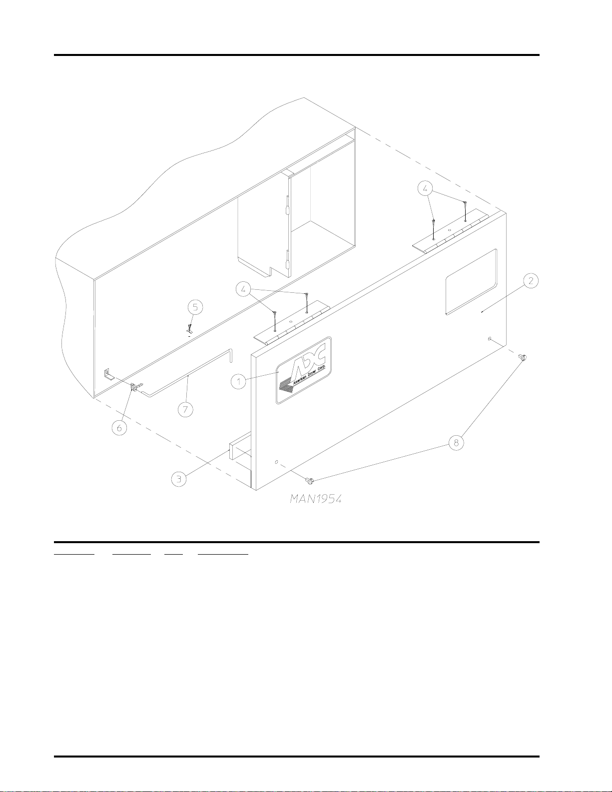
Control Door Assembly Without Trim
Illus. No. Part No. Qty. Description
1 882052 1 ADC Logo ONLY
870011 1 Logo Double Adhesive Tape Kit ONLY
2 881045* 1 Control Door
(includes illus. nos. 2 and 3)
881046 1 Stainless Steel Control Door
(includes illus. nos. 2 and 3)
3 117604 4 Neoprene Sponge Tape (sold by the foot)
4 150300 4 #10 x 1/2” Hex Washer TEK Screw
5 102600 1 Control Door Rod Support Catch
6 102601 1 Control Door Retainer Clip
7 102502 1 Control Door Rod
8 160005 2 Turn Latch
* Specify color when ordering.
American Dryer Corporation 88 Currant Road / Fall River, MA 02720-4781
Page 5
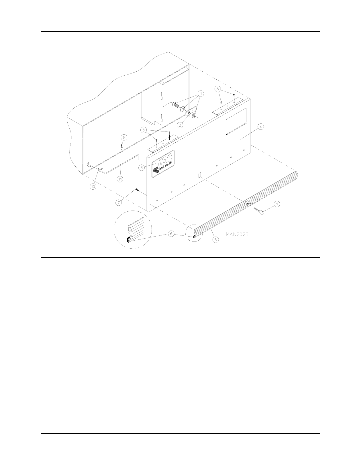
Control Door Assembly W ith Trim
3
Illus. No. Part No. Qty. Description
1 160015 1 High Security MK-100 Lock Assembly with Key
(for Coin Models Only)
160017 1 Special Dummy Lock ONLY
(for non-Coin Models Only)
160104 1 MK-100 Key ONLY
2 160016 1 Lock Cam ONLY
3 882052 1 ADC Logo ONLY
870011 1 Logo Double Tape Kit
4 800020* 1 High Security Control Door Assembly
(includes illus. nos. 4 through 7)
800144 1 Stainless Steel High Security Control Door Assembly
(includes illus. nos. 4 through 7)
5 180202 1 Top Trim Strip (Gray) with Lock Hole (38-1/4” length)
6 117603 3 Suppressor Tape/Gasket (sold by the foot)
7 150201 6 #10-32 x 1/4” Phillips Round Head Machine Screw
8 150309 4 #10-16 x 1/2” Hex Head TEK Crimptite Screw
9 102600 1 Control Door Rod Support Catch
10 102601 1 Control Door Rod Retainer Clip
11 102502 1 Control Door Support Rod
* Specify color when ordering.
Telephone: (508) 678-9000 Fax: (508) 678-9447
Page 6
4
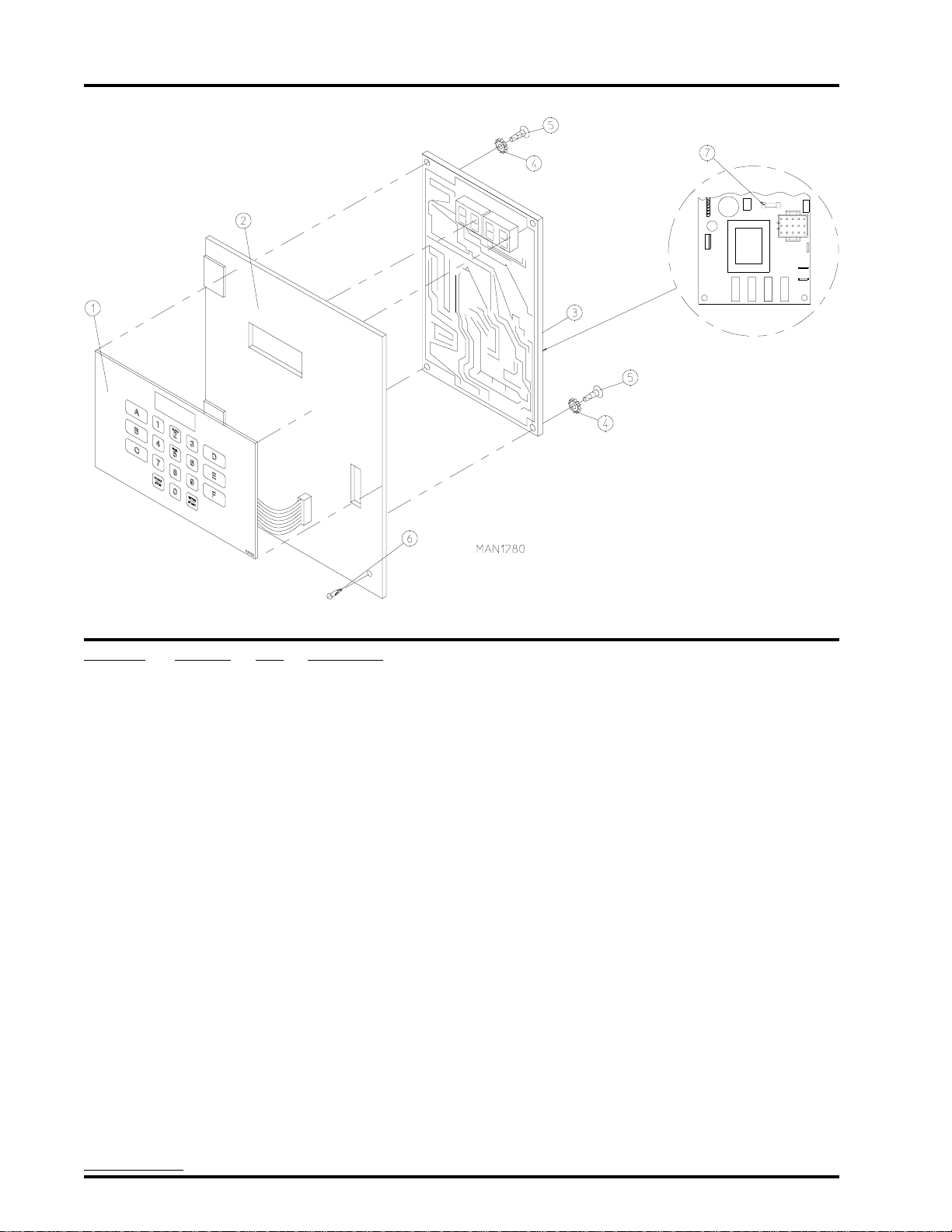
Phase 5 OPL Micr opr ocessor Contr ol Panel Assembly
Illus. No. Part No. Qty. Description
1 112535 1 OPL English Keyboard Label Assembly
112276 1 OPL Stick-on Labels (English ONLY) ... Not Illustrated
112275 1 OPL Stick-on Labels ... Not Illustrated
(Spanish, Italian, and Hebrew)
112277 1 3-Language OPL Stick-on Labels ... Not Illustrated
(English, Spanish, and Hebrew)
112278 1 5-Language OPL Stick-on Labels ... Not Illustrated
(Italian, Dutch, French, German, and Chinese)
2 801255 1 Phase 5 Microprocessor Control Panel ONLY
801256 1 Phase 5 Microprocessor Control Panel ONLY with Battery Bracket
801206 1 Phase 5 OPL Non-Reversing Microprocessor Control Panel Assembly
Complete (includes illus. nos. 1 through 6)
801207 1 Phase 5 OPL Reversing Microprocessor Control Panel Assembly
Complete (includes illus. nos. 1 through 6)
3 137222 1 Phase 5 OPL Non-Reversing Microprocessor Controller (computer) ONLY
137231 1 Phase 5 OPL Reversing Microprocessor Controller (computer) ONLY
824998 1 Phase 5 Battery Clip
4 153010 2 #6 Star Washer
5 150005 2 #6-32 x 1/4” Phillips Round Head Machine Screw
6 150429 1 #10-16 x 1/2” TORX Head Crimptite Screw
150433 1 TORX Hand Driver
(for removal of TORX Head Screw)
7 136048 1 1/8-Amp (Slo Blo) Fuse
IMPORTANT: Check label on computer chip to verify correct part number for controller (computer).
American Dryer Corporation 88 Currant Road / Fall River, MA 02720-4781
Page 7
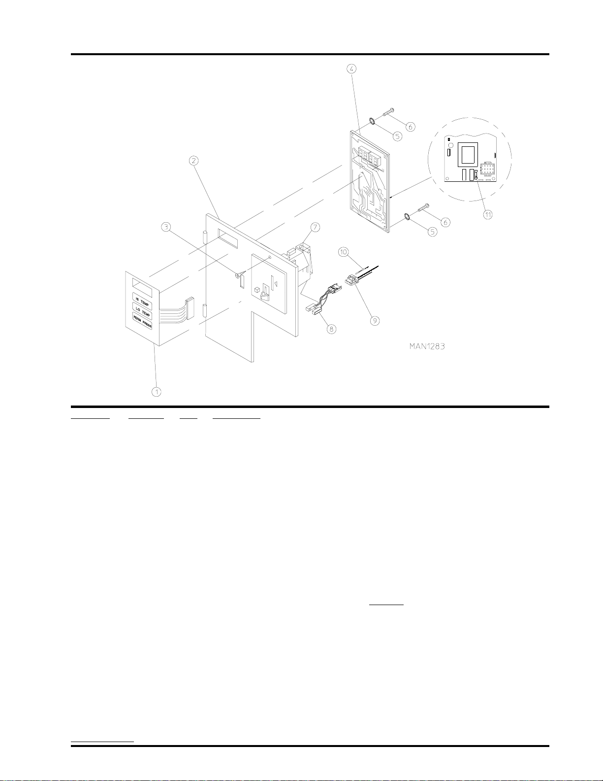
Phase 5 Coin Microprocessor Control Panel Assembly
5
Illus. No. Part No. Qty. Description
1 112526 1 Coin Keyboard Label Assembly
2 801213 1 Phase 5 Coin Control Panel Assembly
(includes illus. nos. 1, 2, 4, 5, and 6)
801229 1 Phase 5 Coin Control Panel Assembly with Battery Option
(includes illus. nos. 1, 2, 4, 5, and 6)
801259 1 Coin Control Panel ONL Y
801258 1 Coin Control Panel ONL Y with Battery Bracket
3 150309 1 #10-16 x 1/2” Hex Head TEK Crimptite Screw
4 137213 1 Phase 5 Coin Microprocessor Controller (computer) ONLY
824998 1 Phase 5 Battery Clip
5 153010 2 #6 Star Washer
6 150005 2 #6-32 x 1/4” Phillips Round Head Machine Screw
7 -------- 1 Coin Acceptor
(refer to Coin Acceptors Listing on page 43)
8* 137056 1 Optic Switch ONLY
9* 137023 1 Optic Switch Connector ONLY
10 137021* 3 Microprocessor Socket ONLY
880772 1 Single Coin Optical Switch Harness
824080 1 Dual Coin Optical Switch Harness
122800 1 Microprocessor (female) Pin Extraction Tool
1 1 136048 1 1/8-Amp (Slo Blo) Fuse
* For dual coin models double the quantity shown.
IMPORTANT: Check label on computer chip to verify correct part number of controller (computer).
Telephone: (508) 678-9000 Fax: (508) 678-9447
Page 8
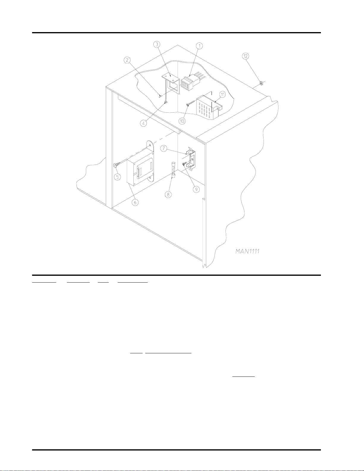
6
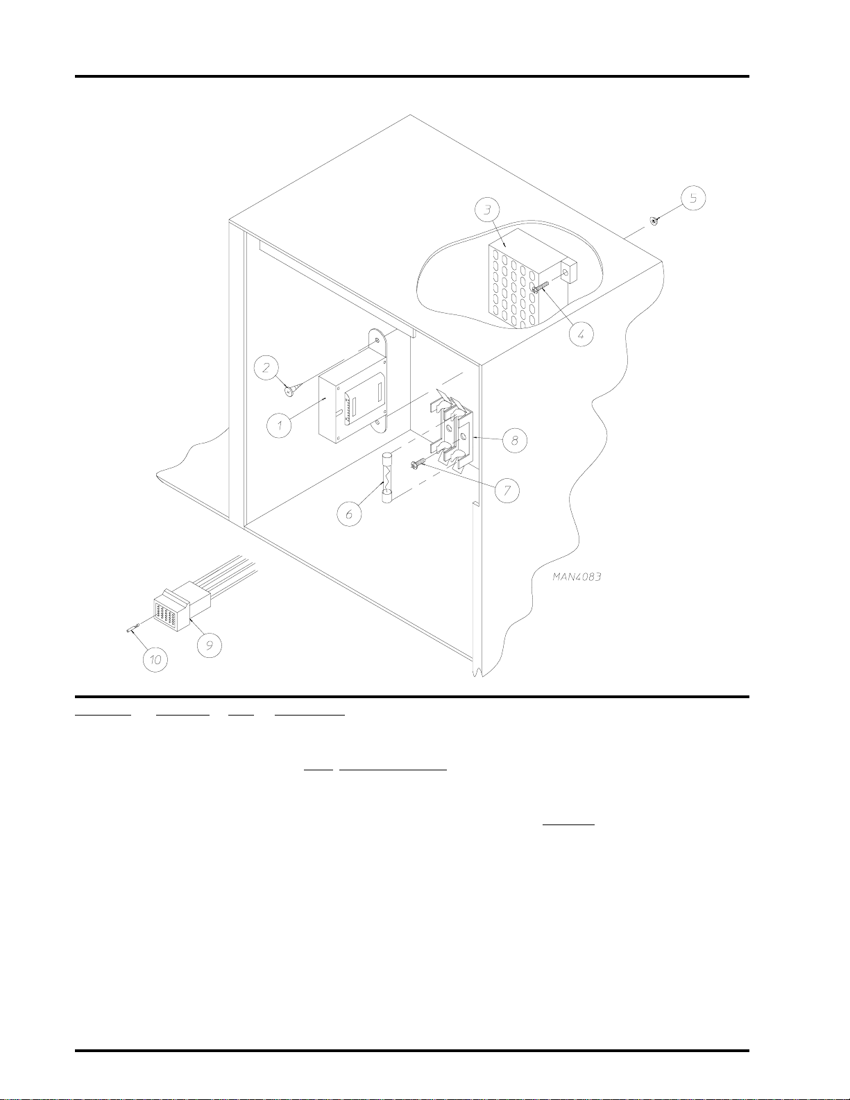
Phase 5 Coin and OPL Micr oprocessor Control Box Assembly
Illus. No. Part No. Qty. Description
1 141403 1 Transformer - 24 VAC
(for ALL 380/416/480 volt Gas and Steam Models)
-------- 1 Transformer - 24 VAC
(for Electric Models Only)
(Refer to Transformer Usage Listing on page 44)
2 150300 2 #10 x 1/2” Hex Washer TEK Screw
3 120715 1 30-Position T erminal Block
4 150002 2 #6-32 x 1” Phillips Round Head Screw
5 151000 2 #6-32 Pal Nut
6 136057 * 1/2-Amp (Slo Blo) Fuse
7 150301 * #8-18 x 7/16” Phillips Pan Head TEK Screw
8 136008 * Fuse Block/Strip ONLY
9 122641 1 15-Pin Microprocessor Connector
10 122706 * Socket ONLY
--- 112801 1 Pin/Socket Extraction T ool
* As required.
American Dryer Corporation 88 Currant Road / Fall River, MA 02720-4781
Page 9
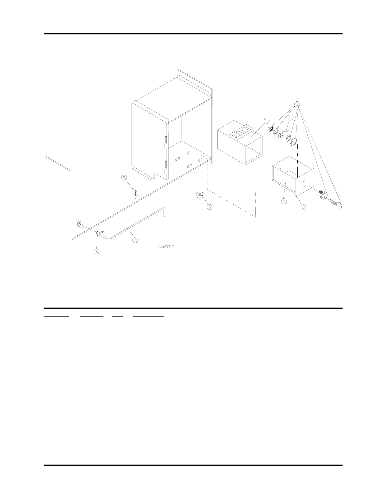
Coin Vault Assembly
7
Illus. No. Part No. Qty. Description
1 802112 1 Microprocessor Coin V ault Assembly Complete
(includes illus. nos. 1 through 6)
802117 1 Microprocessor Coin Vault ONLY
2 160028 1 Cam for 1/4 Turn Lock ONLY
3 875061 1 1/4 Turn Lock with Key and Cam
160105* 1 1/4 Turn Mer-Pel Key ONLY
4 802020 1 1/4 T urn Coin Box Assembly
(includes illus. nos. 2 through 5)
802019 1 1/4 Turn Coin Box ONLY without Face Plate
125915 1 High Security (Greenwald) Coin Box ONLY with Key
5 802018 1 1/4 Turn Coin Box Face Plate ONLY
6 152014 4 1/4-20 Free Spin Wash Nut
7 102502 1 Control Door Support Rod
8 102601 1 Control Door Rod Retainer Clip
9 102600 1 Control Door Rod Catch
* Specify key number when ordering.
Telephone: (508) 678-9000 Fax: (508) 678-9447
Page 10
8
Dual T imer Contr ol Panel Assembly
American Dryer Corporation 88 Currant Road / Fall River, MA 02720-4781
Page 11

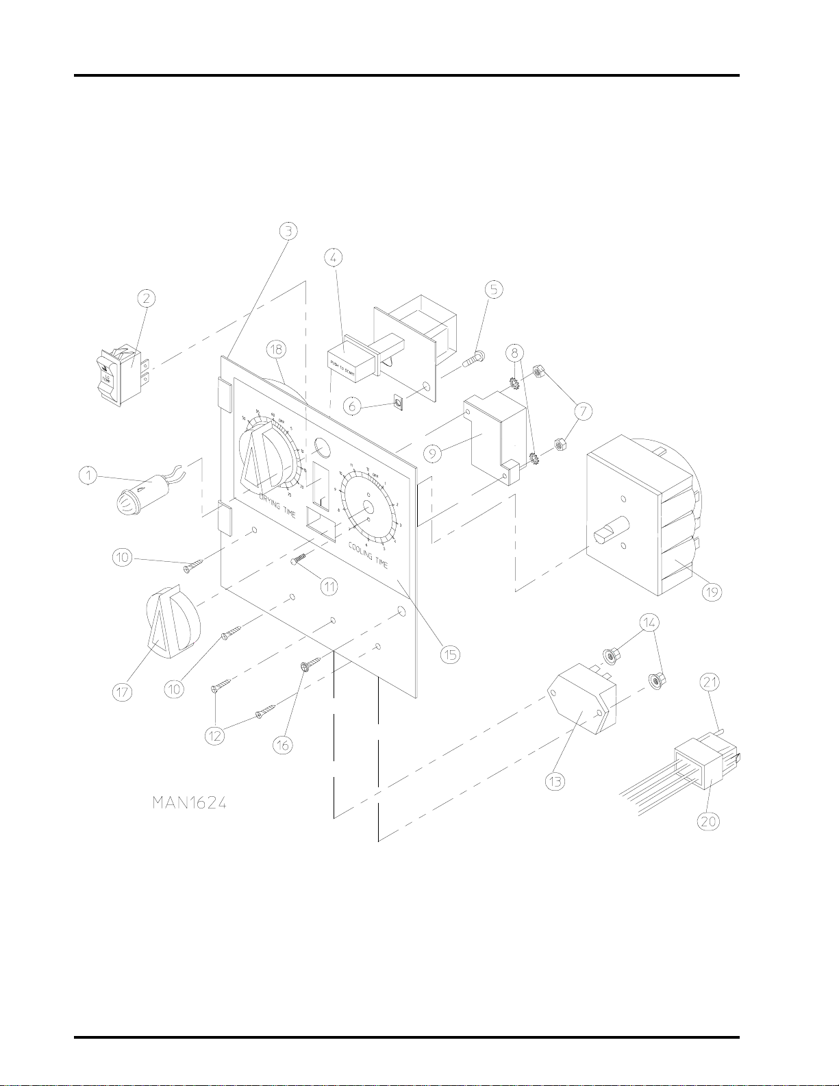
Dual T imer Contr ol Panel Assembly
Illus. No. Part No. Qty. Description
1 123005 1 Red Indicator Light - 24 VAC
2 122400 1 Rocker Heat Selector Switch
3 824015 1 Dual Timer Control Panel Assembly Complete - 24 VAC
(includes illus. nos. 1 through 21)
800051 1 Dual Timer Control Panel ONLY
4 131917 1 Push-to-Start Relay - 24 VAC
5 150207 2 #10-24 x 1/2” Round Head Machine Screw
6 154001 2 #10-24 Speed Nut
7 152000 2 #6-32 Hex Nut
8 153010 2 #6 S tar Washer
9 120730 1 30-Position T erminal Block
10 150002 2 #6-32 x 1” Phillips Round Head Machine Screw
1 1 150110 4 #8-32 x 1/4” Phillips Round Head Machine Screw
12 150001 2 #6-32 x 1/2” Phillips Round Head Machine Screw
13 131931 1 Dual Timer Relay - 24 VAC
14 151000 2 #6-32 Pal Nut
15 112050 1 Dual Timer Label ONLY
16 150309 1 #10-16 x 1/2” Hex Head TEK Crimptite Screw)
17 124103 2 Arrow Timer Knob
18 124025 1 60-Minute Timer - 24 VAC
19 124030 1 15-Minute Timer - 24 VAC
20 122602 1 9-Pin Connector ONLY
21 122700 8 Pin T erminal ONLY
--- 122801 1 Pin/Socket Extraction Tool
9
Telephone: (508) 678-9000 Fax: (508) 678-9447
Page 12
10
Dual T imer Contr ol Box Assembly
Illus. No. Part No. Qty. Description
1 122603 1 9-Pin Socket Connector
2 122701 8 Socket Terminal ONLY
122801 1 Pin/Socket Extraction T ool
3 315010 1 9-Pin Connector Bracket
4 150300 2 #10 x 1/2” Hex Washer TEK Screw
5 150300 2 #10 x 1/2” Hex Washer TEK Screw
6 141403 1 Transformer - 24 VAC
(for ALL 380/416/480 volt Gas and Steam Models)
-------- 1 Transformer - 24 VAC
(for Electric Models Only)
(Refer to Transformer Usage Listing on page 44)
7 136008 * Fuse Block/Strip ONLY
8** 136057 * 1/2-Amp (Slo Blo) Fuse ONLY
9 150301 * #8-18 x 7/16” Phillips Pan Head TEK Screw
10 150002 2 #6-32 x 1” Phillips Round Head Machine Screw
1 1 120715 1 30-Position Terminal Block
12 151000 2 #6-32 Pal Nut
* As required.
** Check fuse rating for verification.
American Dryer Corporation 88 Currant Road / Fall River, MA 02720-4781
Page 13
Front Panel Assembly
11
Illus. No. Part No. Qty. Description
1 875302* 1 Right Hand Insulated Front Panel Assembly Complete
(includes illus. nos. 1, 2, 3, and 6)
875313 1 Stainless Steel Right Hand Insulated Front Panel Assembly Complete
(includes illus. nos. 1, 2, 3, and 6)
2 154215 2 5/32” Pop Rivet
3 170330 1 Friction Door Latch
4 150300 1 #10 x 1/2” Hex Washer TEK Screw
5 150309 8 #10-16 x 1/2” Hex Head TEK Crimptite Screw
6 121405 1 Rubber Grommet
* Specify color when ordering.
Telephone: (508) 678-9000 Fax: (508) 678-9447
Page 14
12
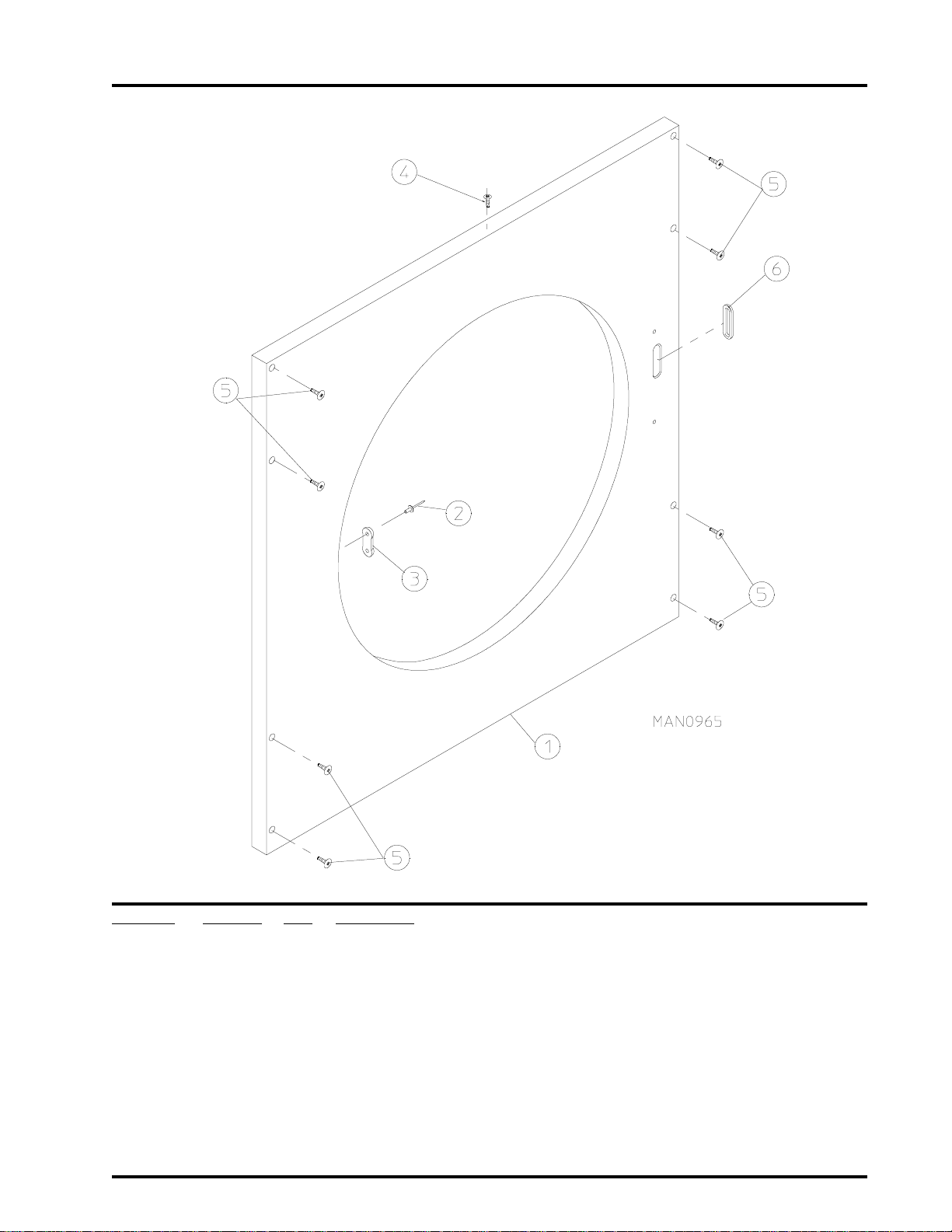
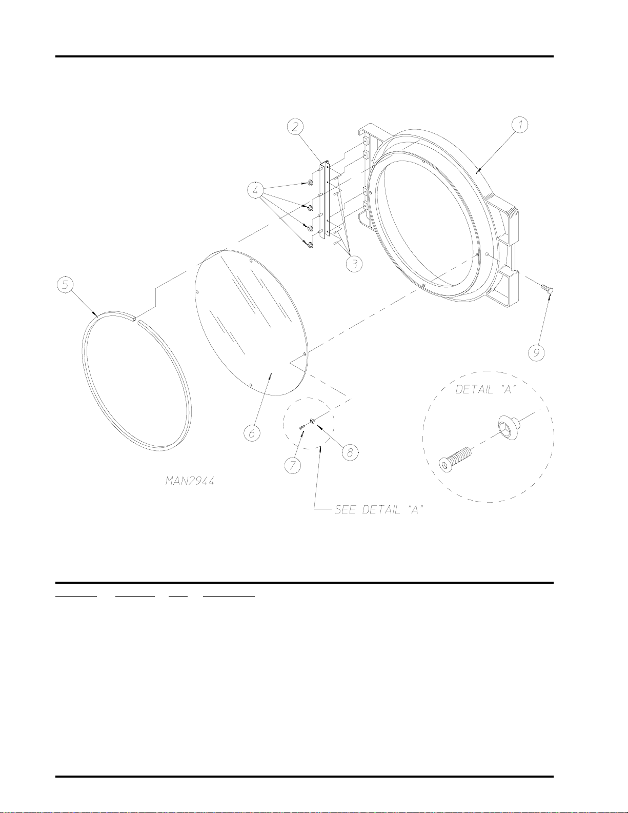
Main Door Assembly
Illus. No. Part No. Qty. Description
1 881421 1 Gray Plastic Main Door Assembly Complete with Mechanical Fasteners
(includes illus. nos. 1 and 5 through 9)
2 800448 4 12-1/2” Stainless Steel Main Door Hinge Assembly
3 150410 4 #10-24 x 3/8” Phillips Pan Head Taptite Screw
4 152014 4 1/4-20 Free Spin Wash Nut
5 102349 1 Main Door Gasket
6 102212 1 20-7/16” Door Glass with (4) Holes
170730 1 Main Door Glass Adhesive (10.3 oz. cartridge)
7 150448 4 1/2” Stainless Steel Flat Head Allen Screw
8 170319 4 Door Glass (Nylon) Spacer
9 150431 1 Main Door Latch Screw
(#10 x 7/16” Dome Hex Head)
American Dryer Corporation 88 Currant Road / Fall River, MA 02720-4781
Page 15
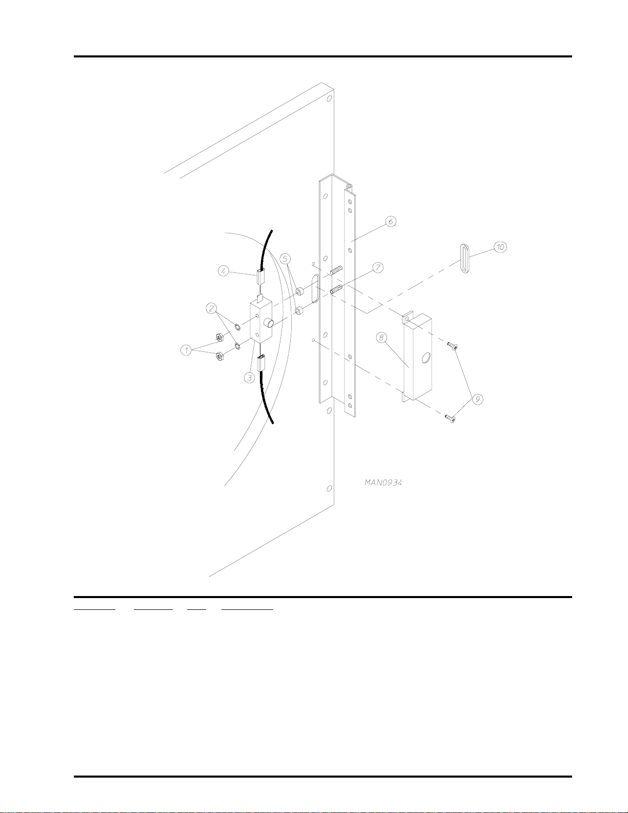
Main Door Switch Housing
13
Illus. No. Part No. Qty. Description
1 152013 2 #6-32 Hex Nut
2 153008 2 #6 Lock Washer
3 137005 1 Single-Pole Door Switch
4 121028 2 Insulated Female T erminal
5 154281 2 3/8” Standard Nylon Spacer
6 800448 1 12-1/2” Stainless Steel Main Door Hinge Assembly
(includes illus. nos. 6 and 7)
7 153565 2 #6-32 x 1” Self Clinching Stud
8 313218 1 Main Door Switch Housing
9 150201 2 #10-32 x 1/4” Phillips Pan Head Machine Screw
10 121405 1 Rubber Grommet
Telephone: (508) 678-9000 Fax: (508) 678-9447
Page 16

14
Basket (T umbler)/Support Assemblies
American Dryer Corporation 88 Currant Road / Fall River, MA 02720-4781
Page 17

Basket (T umbler)/Support Assemblies
Illus. No. Part No. Qty. Description
1* 800708 1 Basket (Tumbler) ONLY without Felt Collar
800857 1 Stainless Steel Basket (Tumbler) ONLY without Felt Collar
800816 1 Non-Reversing Basket (Tumbler) and Support Assembly Complete
(includes illus. nos. 1 through 10)
800873 1 Stainless Steel Non-Reversing Basket (Tumbler) and Support Assembly
Complete
(includes illus. nos. 1 through 10)
800819 1 Reversing Basket (Tumbler) and Support Assembly Complete
(includes illus. nos. 1 through 10)
800876 1 Stainless Steel Reversing Basket (Tumbler) and Support Assembly Complete
(includes illus. nos. 1 through 10)
2 150413 40 #10-16 x 1/2” TORX Head Crimptite Screw
150429 1 TORX Hand Driver
(for removal of TORX Head Screw)
3 301308 4 Basket (Tumbler) Rib ONLY
301408 4 Stainless Steel Basket (Tumbler) Rib ONLY
4 150500 1 5/16-18 x 3/4” Socket Button Head Screw
5 100905 4 3/8-16 x 37” Tie Rod
6 153004 4 3/8” Flat Washer
7 800613 1 Non-Reversing Basket (Tumbler) Support ONLY
800615 1 Reversing Basket (Tumbler) Support ONLY
8 152005 4 3/8” Hex Nut
9 153005 4 3/8” Lock Washer
10 153004 4 3/8” Flat Washer
1 1 116000 1 Felt Collar ONLY
--- 401010 1 #847 Adhesive For Felt Collar
15
* Felt collar is not included and must be ordered separately.
Telephone: (508) 678-9000 Fax: (508) 678-9447
Page 18

16
Dr op Lint Door Assembly Without T rim
Illus. No. Part No. Qty. Description
1 160001 1 AD-100 Lock Assembly with Key (for Coin Models Only)
160103 1 AD-100 Key ONL Y
800150 1 Knob Latch Kit Assembly
(includes illus. nos. 1 and 2)
160200 1 Knob Latch ONLY with 2 Screws (without cam)
160003 1 Dummy Lock ONLY (for Non-Coin Models)
160104 1 MK-100 Key ONLY (for Dummy Lock)
2 160008 1 Lock Cam for AD-100 and Dummy Lock
160009 1 Knob Latch Adjustable Cam ONLY
150425 1 #12-24 x 3/8” Round Head Machine Screw ONLY
(screw for Knob Latch Adjustable Cam)
3 157000 1 Drop Lint Door Spring
4 802104* 1 Insulated Drop Lint Door Assembly
(includes illus. nos. 4 through 8)
882106 1 Stainless Steel Insulated Drop Lint Drawer Assembly
(includes illus. nos. 4 through 8)
5 150201 6 #10-32 x 1/4” Phillips Pan Head TEK Screw
6 117604 7 Neoprene Sponge Tape (sold by the foot)
7 150419 2 #6 x 1/2” Tamperproof TEK Screw
150418 1 Tamperproof Screw Hand Driver
8 108120 1 Chain for Drop Lint Door (10-1/2” length)
* Specify color when ordering.
American Dryer Corporation 88 Currant Road / Fall River, MA 02720-4781
Page 19

Dr op Lint Door Assembly With Trim
17
Illus. No. Part No. Qty. Description
1 160001 1 AD-100 Lock Assembly with Key (for Coin Models Only)
160103 1 AD-100 Key ONL Y
800150 1 Knob Latch Kit Assembly
(includes illus. nos. 1 and 2)
160200 1 Knob Latch ONLY with 2 Screws (without cam)
160003 1 Dummy Lock ONLY (for Non-Coin Models)
160104 1 MK-100 Key ONLY (for Dummy Lock)
2 160008 1 Lock Cam for AD-100 and Dummy Lock
160009 1 Knob Latch Adjustable Cam ONLY
150425 1 #12-24 x 3/8” Round Head Machine Screw ONLY
(screw for Knob Latch Adjustable Cam)
3 157000 1 Drop Lint Door Spring
4 800237* 1 Insulated Drop Lint Door Assembly
(includes illus. nos. 4 through 8)
880229 1 Stainless Steel Insulated Drop Lint Drawer Assembly
(includes illus. nos. 4 through 8)
5 150201 6 #10-32 x 1/4” Phillips Pan Head TEK Screw
6 117604 7 Neoprene Sponge Tape (sold by the foot)
7 117603 3 Suppressor Tape/Gasket (sold by the foot)
8 180212 1 Mid Trim/Kick Plate - Gray (8-1/4” length)
9 150419 2 #6 x 1/2” Tamperproof TEK Screw
150418 1 Tamperproof Screw Hand Driver
10 108120 1 Chain for Drop Lint Door (10-1/2” length)
* Specify color when ordering.
Telephone: (508) 678-9000 Fax: (508) 678-9447
Page 20

18
Lint T rap Assembly
Illus. No. Part No. Qty. Description
1 800420 1 Non-Reversing and Reversing Lint Trap Assembly Complete
(includes illus. nos. 1, 3, 4, and 5)
850181 1 Non-Reversing and Reversing Lint Trap ONLY
2 154200 7 5/32” Pop Rivet
3 304101 1 Lint Screen Holder ONLY
4 150300 3 #10 x 1/2” Hex Washer TEK Screw
5 800506 1 Lint Screen ONLY
6 150419 2 #6 x 1/2” Tamperproof TEK Screw
7 108120 1 Chain for Drop Lint Door (10-1/2” length)
- 150418 1 Tamperproof Screw Hand Driver
American Dryer Corporation 88 Currant Road / Fall River, MA 02720-4781
Page 21

Idler Bearing Assembly
19
Illus. No. Part No. Qty. Description
1 100108 1 5L-680 V-Belt (idler to basket [tumbler])
2 1 01140 1 14” x 3” Compound Pulley
3 100117 1 4L-620 V-Belt (idler to motor)
For Non-Reversing Models ONLY
100114 1 4L-630 V-Belt (idler to motor)
For Reversing Models ONLY
4 154301 2 5/16-18 x 1” Allen Setscrew
5 100705 1 3/16” x 3/16” x 1-3/8” Key
6 301850 1 5/8” x 3/4” Idler Shaft
7 150529 3 1/4-20 x 2-1/4” Carriage Bolt
8 880214 2 5/8” Flange Bearing
9 153007 3 1/4” Lock Washer
10 152002 3 1/4-20 Hex Nut
1 1 801007 1 Idler Bearing Assembly Complete
(includes illus. nos. 5 through 17)
12 150617 2 3/8-16 x 1” Hex Head Machine Bolt
13 153005 2 3/8” Lock Washer
14 153004 2 3/8” Flat Washer
15 801009 1 Idler Square Washer
16 152004 1 5/16-18 Hex Nut
17 150509 1 5/16-18 x 3” Hex Head Machine Bolt
Telephone: (508) 678-9000 Fax: (508) 678-9447
Page 22

20
T umbler Bearing Assembly
American Dryer Corporation 88 Currant Road / Fall River, MA 02720-4781
Page 23

T umbler Bearing Assembly
Illus. No. Part No. Qty. Description
1 880220 1 1-3/4” Flange Bearing
2 153025 4 9/16” Lock Washer
3 152050 4 9/16-12 Hex Nut
4 150508 2 3/8-16 x 3/4” Hex Head Machine Bolt
5 153005 2 3/8” Lock Washer
6 152005 2 3/8-16 Hex Nut
7 150600 2 3/8-16 x 1-1/2” Hex Head Machine Bolt
8 153004 * 3/8” Flat Washer
9 153005 2 3/8” Lock Washer
10 152005 2 3/8-16 Hex Nut
11 150501 4 5/16-18 x 3/4” Hex Head Machine Bolt
12 153002 4 5/16” Lock Washer
13 153001 4 5/16” Flat Washer
14 150621 2 5/16-18 x 1-1/2” Hex Head Machine Bolt
15 152004 2 5/16-18 Hex Nut
16 80 110 1 1 1-3/8” Bearing Box Assembly Complete
(includes illus. nos. 4 through 20)
For models mfd. without Rotational Sensor
801103 1 1-3/8” Bearing Box and Support ONLY
(includes illus. nos. 4, 5, 6, 16, and 17)
801105 1 1-3/8” Bearing Box ONLY
17 80 1 10 4 1 Pillow Block Bearing Support ONL Y
18 880202 1 1-3/8” Pillow Block Bearing ONLY
880779 1 1-3/8” Pillow Block Bearing Assembly with Magnet
(for models mfd. with Optional Rotational Sensor)
19 152004 2 5/16-18 Hex Nut
20 150610 2 5/16-18 x 1-1/2” Allen Setscrew
21 101 1 00 1 18” Pulley
(for Non-Reversing Models Only)
10 1 1 18 1 18-3/4” Pulley
(for Reversing Models Only)
22 101119 1 1-3/8” Taper Lock Hub (key is not included)
For Reversing Models ONLY
23 154301 2 5/16-18 x 5/16” Allen Setscrew
(for Non-Reversing Models Only)
24 100735 1 Shaft Key (f or taper lock h ub)
For Reversing Models ONLY
25 100108 1 5L-680 V-Belt (idler to basket [tumbler])
26 824807 1 Rotational Sensor Assembly
(for models mfd. with Optional Rotational Sensor)
21
* As required.
Telephone: (508) 678-9000 Fax: (508) 678-9447
Page 24

22
Non-Reversing Totally Enclosed, Fan-Cooled (T.E.F.C.) Motor Mount Assembly
American Dryer Corporation 88 Currant Road / Fall River, MA 02720-4781
Page 25

Non-Reversing Totally Enclosed, Fan-Cooled (T.E.F.C.) Motor Mount Assembly
Illus. No. Part No. Qty. Description
1 100117 1 4L-620 V-Belt (motor to idler)
2 100701 1 3/16” x 3/16 ” x 1” Key
3 1 0 1133 1 5/8” x 2-1/4” Motor Pulley (60 Hz Only)
10 1130 1 5/8” x 2-1/2” Motor Pulley (50 Hz Only)
4 150501 4 5/16-18 x 3/4” Hex Head Machine Bolt
5 153002 4 5/16” Lock Washer
6 153001 4 5/16” Flat Washer
7* 100073 1 1 HP 120/208/230v 1ø 60 Hz T.E.F.C. Motor with Plug (56Z frame)
8 122701 8 Socket T erminal
122801 1 Pin/Socket Extraction T ool
9 137030 1 8-Pin Housing Connector
10 152004 4 5/16-18 Hex Nut
11 153002 4 5/16” Lock Washer
12 153001 4 5/16” Flat Washer
13 117604 4 Neoprene Sponge Tape (sold by the foot)
14 154000 4 5/16-18 Tinnerman Nut
15 800919 1 Non-Reversing Motor Mount ONLY (56Z frame)
803992* 1 1 HP 120/230v 1ø 60 Hz T.E.F.C. Motor Mount Assembly with Plug
Complete (includes illus. nos. 2 through 7 and 13 through 20)
803953 1 3/4 HP 230v 1ø 50 Hz Non-Reversing T.E.F.C. Motor Mount Assembly
Complete
(includes illus. nos. 2 through 6 and 13 through 22)
803955* 1 1 HP 230/380/460v 3ø 60 Hz Non-Reversing T.E.F.C. Motor Mount
Assembly Complete
(includes illus. nos. 2 through 6 and 13 through 22)
803958* 1 1 HP 230/380/460v 3ø 50 Hz Non-Reversing T.E.F.C. Motor Mount
Assembly Complete
(includes illus. nos. 2 through 6 and 13 through 22)
16 153051 1 3/4” S.A.E. Flat Washer
17 100603 1 16” Impellor with 3/4” Bore
18 100714 1 3/16” x 3/16” x 1-7/8” Key
19 153050 2 1/2” S.A.E. Flat Washer
20 152006 2 1/2-20 Left Hand Jam Nut
21 120200 1 3/8” x 90° Connector
22 100075* 1 1 HP 208/230/240/460v 3ø 50/60 Hz T.E.F.C. Motor
100076 1 3/4 HP 230v 1ø T.E.F.C. Motor (50 Hz Only)
23
* Specify voltage when ordering.
Telephone: (508) 678-9000 Fax: (508) 678-9447
Page 26

24
Reversing Totally Enclosed, Fan-Cooled (T.E.F.C.) Motor Mount Assembly
for ALL Gas and Electric Models ONLY
American Dryer Corporation 88 Currant Road / Fall River, MA 02720-4781
Page 27

Reversing Totally Enclosed, Fan-Cooled (T.E.F.C.) Motor Mount Assembly
for ALL Gas and Electric Models ONLY
Illus. No. Part No. Qty. Description
1 100114 1 4L-630 V-Belt (to idler assembly)
2 100701 1 3/16” x 3/16 ” x 1” Key
3 1 0 1130 1 5/8” x 2-1/2” Motor Pulley (60 Hz Only)
10 1139 1 5/8” x 2-3/4” Motor Pulley (50 Hz Only)
4 120200 1 3/8” x 90° Connector
5 181003 1 1/2 HP 208/230/380/460v 3ø 50/60 Hz T.E.F.C. Motor (56Z frame)
6 150501 4 5/16-18 x 3/4” Hex Head Machine Bolt
7 153002 4 5/16” Lock Washer
8 153001 4 5/16” Flat Washer
9* 100075 1 1 HP 220/230/380/460v 3ø 50/60 Hz T.E.F.C. Motor with 3/4” Shaft
(56Z frame)
10 120200 1 3/8” x 90° Connector
11 150501 4 5/16-18 x 3/4” Hex Head Machine Bolt
12 153002 4 5/16” Lock Washer
13 153001 4 5/16” Flat Washer
14 154000 8 5/16” Tinnerman Nut
15 152004 7 5/16” Hex Nut
16 153002 7 5/16” Lock Washer
17 153001 7 5/16” Flat Washer
18 800920 1 Reversing Motor Mount ONLY (56Z frame)
803952** 1 60 Hz Reversing T.E.F.C. Motor Mount Assembly Complete
(includes illus. nos. 2 through 14 and 18 through 24)
803987** 1 50 Hz Reversing T.E.F.C. Motor Mount Assembly Complete
(includes illus. nos. 2 through 14 and 18 through 24)
19 117604 4 Neoprene Sponge Tape (sold by the foot)
20 153051 1 3/4” S.A.E. Flat Washer
21 100714 1 3/16” x 3/16” x 1-7/8” Key
22 100603 1 16” Impellor with 3/4” Bore
23 153050 *** 1/2” S.A.E. Flat Washer
24 152006 2 1/2-20 Left Hand Jam Nut
25
* Check part number on motor data label to verify correct motor.
** Specify voltage when ordering.
*** As required.
Telephone: (508) 678-9000 Fax: (508) 678-9447
Page 28

26
Reversing Totally Enclosed, Fan-Cooled (T.E.F.C.) Motor Mount Assembly
for S team Models ONLY
American Dryer Corporation 88 Currant Road / Fall River, MA 02720-4781
Page 29

Reversing Totally Enclosed, Fan-Cooled (T.E.F.C.) Motor Mount Assembly
for S team Models ONLY
Illus. No. Part No. Qty. Description
1 100114 1 4L-630 V-Belt (motor to idler)
2 100701 1 3/16” x 3/16 ” x 1” Key
3 1 0 1130 1 5/8” x 2-1/2” Motor Pulley (60 Hz Only)
10 1139 1 5/8” x 2-3/4” Motor Pulley (50 Hz Only)
4 120200 1 3/8” x 90° Connector
5 181003 1 1/2 HP 208/230/380/460v 3ø 50/60 Hz T.E.F.C. Motor (56Z frame)
6 150501 4 5/16-18 x 3/4” Hex Head Machine Bolt
7 153002 4 5/16” Lock Washer
8 153001 4 5/16” Flat Washer
9* 100075 1 1 HP 220/230/380/460v 3ø 50/60 Hz T.E.F.C. Motor with 3/4” Shaft
(56Z frame)
10 120200 1 3/8” x 90° Connector
11 150501 4 5/16-18 x 3/4” Hex Head Machine Bolt
12 153002 4 5/16” Lock Washer
13 153001 4 5/16” Flat Washer
14 154000 8 5/16” Tinnerman Nut
15 152004 7 5/16” Hex Nut
16 153002 7 5/16” Lock Washer
17 153001 7 5/16” Flat Washer
18 800920 1 Reversing Motor Mount ONLY (56Z frame)
803952** 1 60 Hz Reversing T.E.F.C. Motor Mount Assembly Complete
(includes illus. nos. 2 through 14 and 18 through 24)
803987** 1 50 Hz Reversing T.E.F.C. Motor Mount Assembly Complete
(includes illus. nos. 2 through 14 and 18 through 24)
19 117604 4 Neoprene Sponge Tape (sold by the foot)
20 153051 1 3/4” S.A.E. Flat Washer
21 100702 1 1/8” x 1/8” x 1-1/2” Key
22 100603 1 16” Impellor with 3/4” Bore
23 153050 *** 1/2” S.A.E. Flat Washer
24 152006 2 1/2-20 Left Hand Jam Nut
27
* Check part number on motor data label to verify correct motor.
** Specify voltage when ordering.
*** As required.
Telephone: (508) 678-9000 Fax: (508) 678-9447
Page 30

28
Sensor Bracket Assemblies
Microprocessor Sensor Bracket Assembly
MAN0238
Non-Computer Sensor Bracket Assembly
American Dryer Corporation 88 Currant Road / Fall River, MA 02720-4781
Page 31

Sensor Bracket Assemblies
Illus. No. Part No. Qty. Description
1 880251 1 1/4 ” Temperature Sensor Probe Assembly
(includes illus. nos. 1 and 5 through 8)
2 130103 1 225° Large Automatic Reset Thermostat
3 153010 2 #6 S tar Washer
4 152000 2 #6-32 Hex Nut
5 121028 2 Insulated T erminal ONLY
6 122701 4 Socket Terminal ONL Y
112801 1 Pin/Socket Extraction T ool
7 122605 1 4-Pin Socket Connector ONLY
8 154007 2 1/4” Tinnerman Push-on Fastener
9 150005 2 #6-32 x 1/4” Round Head Machine Screw
10 801425 1 Microprocessor Sensor Bracket Assembly Complete
(includes illus. nos. 1 through 10)
305007 1 Universal Sensor Bracket ONLY
11 122604 1 4-Pin Connector ONLY
12 122700 4 Pin T erminal ONLY
13 150301 2 #8-18 x 7/16” Phillips Pan Head TEK Screw
14 150005 * #6-32 x 1/4” Phillips Round Head Machine Screw
15 130111 1 130° Large Thermostat )
16 130100 1 150° Large Thermostat
17 130103 1 225° Large Automatic Reset Thermostat
18 130101 1 180° Large Thermostat
19 153010 * #6 S tar Washer
20 152000 * #6-32 Hex Nut
21 840065 1 Sensor Jumper (4) ONLY
22 121028 * Insulated T erminal ONLY
23 122701 * Socket Terminal ONL Y
24 122605 1 4-Pin Socket Connector ONLY
840062 1 Sensor (4) Bracket Harness Assembly
(includes illus. nos. 22, 23, and 24)
25 801418 1 Non-computer Sensor (4) Bracket Assembly Complete
(includes Thermostats) (includes illus. nos. 14 through 25)
305007 1 Universal Sensor Bracket ONLY
26 122604 4-Pin Connector ONLY
27 122700 * Pin T erminal ONLY
122801 1 Pin/Socket Extraction T ool
28 150301 2 #8-18 x 7/16” Phillips Pan Head TEK Screw
29
* As required.
Telephone: (508) 678-9000 Fax: (508) 678-9447
Page 32

30
Hot Surface Ignition (HSI) Burner Assembly
American Dryer Corporation 88 Currant Road / Fall River, MA 02720-4781
Page 33

Hot Surface Ignition (HSI) Burner Assembly
Illus. No. Part No. Qty. Description
1 881781* 1 Natural Gas Burner Assembly Complete Less Orifices
(includes illus. nos 1 through 9 and 11 through 29)
For models mfd. with Natural Gas ONLY
881784* 1 L.P. (liquid propane) Gas Burner Assembly Complete Less Orifices
(includes illus. nos 1 through 9 and 11 through 29)
For models mfd. with L.P. (liquid propane) Gas ONLY
802237 1 Burner Box ONLY
881231** 1 ADG-75THS L.P. Conversion Kit
2 318041 1 Burner Box Front ONLY
3 150309 5 #10-16 x 1/2” Hex Head TEK Crimptite Screw
4 810029 1 Hot Surface Ignition (HSI) Module Mounting Bracket
5 881797 1 HSI (Hot Surface Ignition) Module II
6 141105 4 Large Burner Tube
7 150103 4 #8-32 x 1/2” Phillips Round Head Machine Screw
8 153000 4 #8 Steel Burr
9 151001 4 #8-32 Pal Nut
10** 140820 4 #29 Burner Orifice (natural gas) ONLY
140804 4 #48 Burner Orifice (liquid propane gas) ONLY
11 141210 1 4-Port Manifold
12 318700 2 Pipe Bracket
13 150300 2 #10 x 1/2” Hex Washer TEK Screw
14 128927 1 1/2” 24 VAC Redundant (natural gas) Gas Valve
880960 1 1/2” 24 VAC L.P . (liquid propane) Gas Valve Assembly
140411 1 24 V AC Gas V alve L.P. (liquid propane) Conversion Kit
15 881367 1 1/2’ Union Shut Of f with Tail Piece
16 142809 1 1/2” x 29-1/8” Nipple
17 323737 1 Pipe Bracket
18 319704 1 Hi-Limit Mounting Bracket
19 151000 2 #6-32 Pal Nut
20 150001 2 #6-32 x 1/2” Phillips Round Head Machine Screw
21 130201 1 330º Manual Reset Hi-Limit ONLY
22 -------- 1 Sail Switch
(refer to Sail Switch Assembly on
23 143000 1 3/4” to 1/2” Reducing Coupling
24 150309 2 #10-16 x 1/2” Hex Head TEK Crimptite Screw
25 150309 2 #10-16 x 1/2” Hex Head TEK Crimptite Screw
26 151001 2 #8-32 Pal Nut
27 150309 3 #10-16 x 1/2” Hex Head TEK Crimptite Screw
28 128921 1 HSI Flame Sensor
29 150301 1 #8-18 x 7/16” Phillips Pan Head TEK Screw
30 881597 1 Hot Surface Ignitor (2-1/2” length) - 24 VAC
31 150309 1 #10-16 x 1/2” Hex Head TEK Crimptite Screw
page 35)
31
* Burner orifices are not included and must be ordered separately.
** Consult factory for elevations over 2,000 feet.
Telephone: (508) 678-9000 Fax: (508) 678-9447
Page 34

32
Electric Oven Assembly
ELECTRIC OVEN (FRONT VIEW)
ELECTRIC OVEN (REAR VIEW)
American Dryer Corporation 88 Currant Road / Fall River, MA 02720-4781
Page 35

Electric Oven Assembly
Illus. No. Part No. Qty. Description
1 803005 1 Large Electric Oven Box ONLY
--------* 1 Electric Oven Assembly Complete
2 --------* - Electric Element
3 150300 2 #10 x 1/2” Hex Washer TEK Screw
4 802800 1 Sail Switch Box with Bracket and Cover ONLY
802801 1 Sail Switch Box Assembly Complete
(includes illus. nos. 4 through 12)
5 154004 1 Twin Speed Nut
6 150413 2 #10-16 x 1/2” Phillips Round Head Crimptite Screw
7 802799 1 Sail Switch Box Cover and Bracket ONLY
8 122200 1 Sail Switch ONL Y
9 150303 2 #4 x 3/4” Pan Head “A” Machine Screw
10 105500 1 Sail Switch Actuator Rod
11 319202 1 Sail Switch Damper (flat)
12 154002 1 1/8” Push-on Fastener
13 150300 2 #10 x 1/2” Hex Washer TEK Screw
14 803100 1 Electric Oven Front Cover ONLY
15 320611 1 Large Relay Box Cover ONLY
16 150402 2 #10-24 x 5/8” Slotted Truss Head Machine Screw
17 130400 1 290° Hi-Limit
18 150300 2 #10 x 1/2” Hex Washer TEK Screw
19 154001 1 #10-24 Speed Nut
20 121012 1 Terminal Lug for 1 10-8 W ire
21 152014 3 1/4-20 Free Spin Wash Nut
22 --------* 1 Oven Relay
23 --------* 1 Oven Relay Replacement Coil
24 120081 - Internal Ceramic Insulator (2 per element)
25 120080 - External Ceramic Insulator (2 per element)
26 152008 - #10-32 Hex Nut (4 per element)
27 121011* - Bus Bar
28 --------** - T erminal Lug
29 153009 - #10 Star Washer (2 per element)
30 320607 1 Large Electric Oven Right Side Cover ONLY
31 150402 2 #10-24 x 5/8” Truss Head Machine Screw
33
* Refer to Electric Oven Component Application Chart on
** Consult factory for Wiring Harness required.
page 34.
Telephone: (508) 678-9000 Fax: (508) 678-9447
Page 36

American Dryer Corporation 88 Currant Road / Fall River, MA 02720-4781
34
wKtloVesahPeriW
04614ø34ro322842866.672002146#00233190101211GAFD163131
63802ø34ro31294286651002142#20333142101211JAEG583131
63032ø33 0294286641002142#20333192101211JAEF573131
63614ø34ro31294286651002144#00333142101211GAFD163131
63084/064ø34ro30294286641002142#2033319210121134APD753131
33083ø34ro31294286651002142#20333142101211JAFD163131
03802ø34ro38194286521002164#00333132101211JAEF573131
03032ø33 5394286531002134#00333142101211JAEF573131
03614ø34ro37494286521002148#0013316010121234APD753131
03084/064ø34ro33594286531002148#00133160101212JAFB153131
52083ø34ro30494286521002148#00133160101212JAFB153131
42802ø34ro36194286401002134#0033314210121136APD963131
42032ø33 3394286411002136#00233130101211GAFD163131
*ylbmessAnevO
.oNtraP
.ytQeziS.oNtraP.ytQeziS.oNtraP.ytQ.oNtraP.oN.taC.oNtraP
stnemelEeriWnevOguLlanimreT
raBsuB
110121N/P
yaleRnevO
Electric Oven Component Application Chart
42614ø34ro36494286401002148#00133160101212JAFB153131
42084/064ø34ro325942864110021401#00033160101212JAFB153131
02802ø12 4094285401002124#00333120101212JAEG583131
02032ø12 6294285411002124#00333130101212JAEF573131
02083ø34ro393942864010021401#00033160101212JAFB153131
* Oven assembly complete does not include oven relay. This item must be ordered separately. When ordering Oven Assembly Complete, specify
3 wire or 4 wire when applicable, as well as if dryer has microprocessor (computer) or non-microprocessor controls.
Page 37

Sail Switch Assembly
35
Illus. No. Part No. Qty. Description
1 319203 1 Sail Switch Mounting Bracket
2 319202 1 Sail Switch Damper (flat)
3 319201 1 Sail Switch Box Cover
4 319200 1 Sail Switch Box
5 154004 1 Twin Speed Nut
6 154002 1 1/8" Push-on Fastener
7 150309 4 #10-16 x 1/2” Hex Head TEK Crimptite Screw
8 150303 2 #4 x 3/4" Pan Head “A” Machine Screw
9 122200 1 Sail Switch ONL Y
881706 1 Sail Switch Box Assembly Complete
(includes illus. nos. 1 through 10)
10 105500 1 Sail Switch Actuator Rod
Telephone: (508) 678-9000 Fax: (508) 678-9447
Page 38

36
Non-Reversing Electric Relay Panel Assembly
Computer and Dual Timer Models
Illus. No. Part No. Qty. Description
1 322812 1 Back Electrical Box Component Plate
2 132445 1 12-Amp Contactor Single-Phase (1ø) and 3-Phase (3ø) - 24 VAC
3 137015 1 RC Network
(for microprocessor [computer] models ONLY)
4 150103 2 #8-32 x 3/4” Phillips Round Head Machine Screw
5 151001 2 #8-32 Pal Nut
6 153002 1 5/16” Lock Washer
7 152004 1 5/16-18 Hex Nut
8 120701 1 4-Position T erminal Block
9 150008 2 #6-32 x 1-1/4” Slotted Round Head Machine Screw
10 151000 2 #6-32 Pal Nut
1 1 121300 3 Open/Close Bushing
--- 322809 1 Back Electrical Box Cover ... Not Illustrated
--- 150301 4 #8-18 x 7/16” Phillips Pan Head TEK Screw ... Not Illustrated
--- -------- 1 Transformer ... Not Illustrated
(refer to Step Down Transformer Usage Listing on page 45)
American Dryer Corporation 88 Currant Road / Fall River, MA 02720-4781
Page 39

Micropr ocessor Reversing Rear Contr ol Box Assembly
37
Illus. No. Part No. Qty. Description
1 322812 1 Back Electrical Box Component Plate
2 137060 1 Arc Suppressor Board
3 137013 4 Nylon Standoff
4 132431 1 Reversing Contactor (208/230/240v, 50/60 Hz) - 24 VAC
132432 2 Reversing Contactor Replacement Coil (208/230/240v, 50/60 Hz) - 24 VAC
5 150103 2 8-32 x 3/4” Phillips Round Head Machine Screw
6 151001 2 8-32 Pal Nut
7 153002 1 5/16” Lock Washer
8 152004 1 5/16-18 Hex Nut
9 132430 1 Impellor Contactor (208/230/240v, 50/60Hz) 24 VAC
132432 1 Impellor Contactor Replacement Coil (208/230/240v, 50/60 Hz) - 24 VAC
10 150103 2 8-32 x 3/4” Phillips Round Head Machine Screw
11 151001 2 8-32 Pal Nut
12 120701 1 4-Position Terminal Block
13 150008 2 6-32 x 1-1/4” Slotted Round Head Machine Screw
14 151000 2 6-32 Pal Nut
15 121300 3 Open/Close Bushing
--- 322809 1 Back Electrical Box Cover ... Not Illustrated
-- - 150301 4 #8-18 x 7/16” Phillips Pan Head TEK Screw ... Not Illustrated
--- -------- 1 Transformer
(refer to Step Down Transformer Usage Listing on page 45)
... Not Illustrated
Telephone: (508) 678-9000 Fax: (508) 678-9447
Page 40

American Dryer Corporation 88 Currant Road / Fall River, MA 02720-4781
38
Air Operated Steam Damper Assembly
Page 41

Air Operated Steam Damper Assembly
Illus. No. Part No. Qty. Description
1 165009 1 Steam Coil Assembly
2 153002 6 5/16” Lock Washer
3 152004 6 5/16-18 Hex Nut
4 152002 4 1/4-20 Hex Nut
5 153007 4 1/4” Lock Washer
6 820321 2 Steam Damper Hinge Assembly
7 803415 1 Steam Damper Assembly
(includes illus. nos. 7, 10, and 11)
8 153007 4 1/4” Lock Washer
9 152002 4 1/4-20 Hex Nut
10 115995 108 Steam Damper Gasket (sold by the inch)
11 102350 1 Steam Damper Foam (68-1/2” length)
12 151007 1 7/16-20 Stainless Steel Acorn Nut
13 152007 1 7/16-20 Hex Nut
14 100497 1 1-1/4” Bore x 3” Stroke Piston
15 100492 1 Piston Support Bracket
16 152002 4 1/4-20 Hex Nut
17 153007 4 1/4” Lock Washer
18 100472 1 1/4” x 1/8” Connector
19 143110 1 1/4” Tubing (sold in feet)
20 100472 1 1/4” x 1/8” Connector
21 100496 1 1/8” Needle Valve
22 143238 1 1/8” Close Nipple
23 100498 1 3-Way Micro Valve - 24 VAC
24 150002 2 #6-32 x 1” Phillips Round Head Machine Screw
25 153010 2 #6 S tar Washer
26 152000 2 6-32 Hex Nut
27 330987 1 Micro Valve Support Bracket
28 152002 2 1/4-20 Hex Nut
29 153007 2 1/4” Lock Washer
30 100520 1 1/8” N.P.T. Silencer (muffler)
39
Telephone: (508) 678-9000 Fax: (508) 678-9447
Page 42

40
Dual T imer Reversing Rear Contr ol Box Assembly
Illus. No. Part No. Qty. Description
1 322812 1 Back Electrical Box Component Plate
2 132198 1 Reversing Timer (50/60 Hz) - 24 VAC
3 150301 2 #8-18 x 7/16” Phillips Pan Head TEK Screw
4 132431 1 Reversing Contactor (208/230/240v, 50/60 Hz) - 24 VAC
132432 2 Reversing Contactor Replacement Coil (208/230/240v, 50/60 Hz) - 24 VAC
5 150103 2 #8-32 x 3/4” Phillips Round Head Machine Screw
6 151001 2 #8-32 Pal Nut
7 153002 1 5/16” Lock Washer
8 152004 1 5/16-18 Hex Nut
9 132430 1 Impellor Contactor (208/230/240v, 50/60 Hz) 24 VAC
132432 1 Impellor Contactor Replacement Coil (208/230/240v, 50/60 Hz) - 24 VAC
10 150103 2 #8-32 x 3/4” Phillips Round Head Machine Screw
11 151001 2 #8-32 Pal Nut
12 120701 1 4-Position Terminal Block
13 150008 2 #6-32 x 1-1/4” Slotted Round Head Machine Screw
14 151000 2 #6-32 Pal Nut
15 121300 3 Open/Close Bushing
--- 322809 1 Back Electrical Box Cover ... Not Illustrated
-- - 150301 4 #8-18 x 7/16” Phillips Pan Head TEK Screw ... Not Illustrated
--- -------- 1 Transformer
(refer to Step Down Transformer Usage Listing on page 45)
American Dryer Corporation 88 Currant Road / Fall River, MA 02720-4781
Page 43

Outer Top/Back Guard Assemblies
for Gas and Electric Models ONL Y
41
Illus. No. Part No. Qty. Description
1 322809 1 Rear Electrical Box Cover
2 150301 5 #8-18 x 7/16” Phillips Pan Head TEK Screw
3 323738 1 Top Back Guard
4 150301 6 #8-18 x 7/16” Phillips Pan Head TEK Screw
5 150301 8 #8-18 x 7/16” Phillips Pan Head TEK Screw
6 312527 1 Outer Top Guard
7 314526 1 Lower Back Guard
8 150301 10 #8-18 x 7/16” Phillips Pan Head TEK Screw
9 103500 4 Leveling Leg
Telephone: (508) 678-9000 Fax: (508) 678-9447
Page 44

42
Back Guar d Assembly
for S team Models ONL Y
Illus. No. Part No. Qty. Description
1 314511 1 Bottom Back Guard
2 150300 2 #10 x 1/2” Hex Washer TEK Screw
150301 8 #8-18 x 7/16” Phillips Pan Head TEK Screw
3 322809 1 Rear Electrical Box Cover
4 150301 4 #8-18 x 7/16” Phillips Pan Head TEK Screw
5 103500 4 Leveling Leg
American Dryer Corporation 88 Currant Road / Fall River, MA 02720-4781
Page 45

Coin Acceptors Listing
NOTE: Coin Acceptors listed included Optical Switch (ADC Part No. 137056).
Single Coin*
ADC Part No. Nation Description
125100 U.S. and Canada 25¢ Optic Coin Acceptor
125101 United Kingdom 10 New Pence Optic Coin Acceptor
125114 United Kingdom 20 New Pence Optic Coin Acceptor
125120 France 2 French Franc Optic Coin Acceptor
125124 France 5 French Franc Optic Coin Acceptor
125107 Australia 20¢ Australian Optic Coin Acceptor
125130 Australia $1 Australian Optic Coin Acceptor
125123 New Zealand 50¢ New Zealand Optic Coin Acceptor
881604 Japan 100 Yen Hanke Optic Coin Acceptor
125103 --- .882 Token Optic Coin Acceptor
125121 --- .800 Token Optic Coin Acceptor
125129 --- Muller Token Optic Coin Acceptor
125132 Singapore 50¢ Singapore Optic Coin Acceptor
125133 Hong Kong $1 Hong Kong Optic Coin Acceptor
43
Dual Coin*
881508 U.S. and Canada 10¢ / 25¢ Hanke Dual Optic Coin Acceptor
881842 Canada 25¢ / $1 Hanke Dual Optic Coin Acceptor
881542 United Kingdom 1£ / 20 Pence Hanke Dual Optic Coin Acceptor
881846 France 2 / 5 Franc Hanke Dual Optic Coin Acceptor
125134 Denmark 1 / 5 Danish Krone Dual Optic Coin Acceptor
125126 Netherlands 25¢ / 1 Guilder Dual Optic Coin Acceptor
* Consult factory for coin acceptors not listed.
Telephone: (508) 678-9000 Fax: (508) 678-9447
Page 46

44
Transformer Usage Listing
T
RANSFORMER USAGE LISTING
(for Electric Models Only)
Transformer
for Electric Models ONL Y
Kw V oltage Phase Wir e
Pa rt N o .
Control Rear
40 416 3ø 3 or 4 132070 132062
36 208 3ø 3 132070 -------36 208 3ø 4 132070 -------36 230 3ø 3 or 4 132063 - -- - -- - 36 416 3ø 3 or 4 132070 132062
36 460/480 3ø 3 or 4 141403 132053
33 380 3ø 3 or 4 132070 132059
30 208 3ø 3 or 4 132063 - -- - -- - 30 230 3ø 3 132063 -------30 416 3ø 3 141403 132053
30 460/480 3ø 3 or 4 141403 132053
25 380 3ø 3 or 4 141403 132059
24 208 3ø 3 or 4 132070 - -- - -- - 24 230 3ø 3 132070 -------24 416 3ø 3 or 4 141403 132062
24 460/480 3ø 3 or 4 141403 132053
20 208 1ø 2 132070 -------20 230 1ø 2 132063 -------20 380 3ø 3 or 4 141403 132059
American Dryer Corporation 88 Currant Road / Fall River, MA 02720-4781
Page 47

Step Down Transformer Usage Listing
S
TEP DOWN TRANSFORMER USAGE
L
ISTING
45
Heat V oltage
G
AS
E
LECTRIC
S
TEAM
Wire
Service
380 3 132059
380 4 132059
416 3 132062
416 4 132062
460/480 3 132053
460/480 4 132053
575 3 132050
Transfo rme r
Pa rt No .
Telephone: (508) 678-9000 Fax: (508) 678-9447
Page 48

46
Part No. Description
112039 “Black/White/Green Ground” Label
112280 “Clean Lint Screen” Label
112041 “CAUTION - Exhaust/Lint Screen” Label
112534 “Phase 5 OPL Program Location Summary” Label
114006 “WARNING - Fire Hazards” Label
114094 “MOP HEAD WARNING” Label
117505 Aluminum Duct Tape (sold by the foot)
120100 3/8” Straight (BX) Connector
120300 3/8” x 45° (BX) Connector
120400 3/8” Red Jacket (BX) Insulator
120500 3/8” Jiffy Clip (BX Retainer Clip)
120600 3/8” Greenfield (BX)
120800 1/4” In-Line Connector
120802 Red Butt Connector
120902 #74B Wire Nut
120903 Crimp-on Wire Nut
121014 1/4” Insulated (female) T erminal
121499 4” Harness Tie
121500 7” Harness Tie
121503 Harness Tie Mounting Clip
122804 Manometer (Hydro Gauge) for measuring Gas Pressure
404500 Almond Brush-In-Cap Bottle T ouch-Up Paint
404502 White Brush-In-Cap Bottle Touch-Up Paint
404506 Beige Brush-In-Cap Bottle Touch-Up Paint
404507 Cornflower Blue Brush-In-Cap Bottle Touch-Up Paint
410001 1/2” Allen Wrench (for removal of Shut-Off Valve Tail Piece)
880200 Electrical T erminal (assortment) Kit
880884 Tumbler Bearing Puller
Additional Parts Available
American Dryer Corporation 88 Currant Road / Fall River, MA 02720-4781
Page 49

ADC 450416 1 - 08/06/99-50 2* 04/13/01-25
 Loading...