

Page 1
AD-540
Parts Manual
American Dryer Corporation
88 Currant Road
Fall River, MA 02720-4781
Telephone: (508) 678-9000 / Fax: (508) 678-9447
E-mail: techsupport@amdry.com
www.amdry.com
060901SRS/calbert ADC Part No. 450344
Page 2

Retain This Manual In A Safe Place For Future Reference
American Dryer Corporation products embody advanced concepts in engineering, design, and safety. If this product is
properly maintained, it will provide many years of safe, efficient, and trouble-free operation.
ONLY qualified technicians should service this equipment.
OBSERVE ALL SAFETY PRECAUTIONS displayed on the equipment or specified in the installation manual included with
the dryer.
The following “FOR YOUR SAFETY” caution must be posted near the dryer in a prominent location.
FOR YOUR SAFETY
Do not store or use gasoline or
other flammable vapors and
liquids in the vicinity of this or
any other appliance.
We have tried to make this manual as complete as possible and hope you will find it useful. ADC reserves the right to make
changes from time to time, without notice or obligation, in prices, specifications, colors, and material, and to change or
discontinue models.
POUR VOTRE SÉCURITÉ
Ne pas entreposer ni utiliser d’essence
ni d’autres vapeurs ou liquides
inflammables à proximité de cet
appareil ou de tout autre appareil.
Important
For your convenience, log the following information:
DATE OF PURCHASE ___________________________ MODEL NO. __________________________________________
RESELLER’S NAME ______________________________________________________________________________________
Serial Number(s) ________________________________________________________________________________________
________________________________________________________________________________________
AD-540
________________________________________________________________________________________
Replacement parts can be obtained from your reseller or the ADC factory. When ordering replacement parts from the factory,
you can FAX your order to ADC at (508) 678-9447 or telephone your order directly to the ADC Parts Department at
(508) 678-9000. Please specify the dryer model number and serial number in addition to the description and part number, so
that your order is processed accurately and promptly.
The illustrations on the following pages may not depict your particular dryer exactly. The illustrations are a composite of the
various dryer models. Be sure to check the descriptions of the parts thoroughly before ordering.
“IMPORTANT NOTE TO PURCHASER”
Information must be obtained from your local gas supplier on the instructions
to be followed if the user smells gas. These instructions must be posted in a
prominent location near the dryer.
Page 3
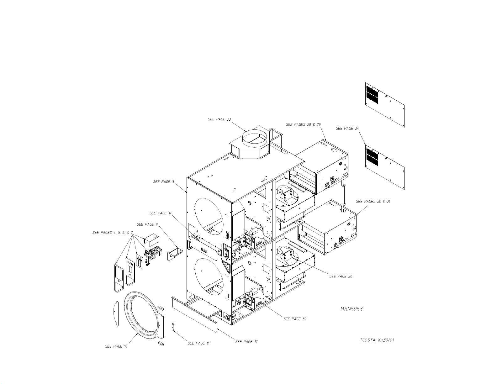
Quick Reference Diagram
For Detailed Information See The Table Of Contents On The Next Page.
Page 4

Table of Contents
Front Panel Assembly ................................................................................................................................... 3
Right Coin Computer Panel Type II
For Models Mfd. as of February 15, 2001 ................................................................................................. 4
Left Coin Computer Panel Type II
For Models Mfd. as of February 15, 2001 ................................................................................................. 5
Left Coin/Computer Assembly
For Models Mfd. prior to February 15, 2001 .............................................................................................. 6
Right Coin/Computer Assembly
For Models Mfd. prior to February 15, 2001 .............................................................................................. 7
Coin Chute Assembly.................................................................................................................................... 8
Coin Box/Vault Assembly (Left and Right).................................................................................................... 9
Main Door “Steel” Assembly ...................................................................................................................... 10
Main Door Switch Assembly ........................................................................................................................11
Basket (Tumbler)/Support Assemblies
For Models Mfd. as of December 12, 2000 ............................................................................................. 12
Basket (Tumbler)/Support Assemblies
For Models Mfd. prior to December 12, 2000.......................................................................................... 13
Top Locking Lint Basket Assembly
For Models Mfd. as of July 17, 2000 ....................................................................................................... 14
Bottom Locking Lint Basket Assembly
For Models Mfd. as of July 17, 2000 ....................................................................................................... 15
Top Lint Basket Assembly
For Models Mfd. prior to July 17, 2000 .................................................................................................... 16
Bottom Lint Drawer/Basket Assembly with Wide Face
For Models Mfd. prior to July 17, 2000 .................................................................................................... 17
Bottom Lint Basket Assembly without Lock
For Models Mfd. prior to July 17, 2000 .................................................................................................... 18
Separator Assembly .................................................................................................................................... 19
Rotational Sensor/Sail Switch and Teflon® Backup Washer Plate ................................................................ 20
Lint Coop and Adjustment Wheel Bracket Assembly................................................................................... 21
Left Rear Wheel Bracket (3-Bolt)
For Models Mfd. as of October 17, 2000................................................................................................. 22
Right Rear Wheel Bracket (3-Bolt)
For Models Mfd. as of October 17, 2000................................................................................................. 23
Rear Thruster Wheel Bracket Assembly
For Models Mfd. prior to October 17, 2000 ............................................................................................. 24
Microprocessor Temperature Sensor Bracket Assembly ............................................................................. 25
Blower Motor Assembly ............................................................................................................................. 26
Rear Electrical Panel .................................................................................................................................. 27
Top Burner Box Assembly ..................................................................................................................... 28, 29
Bottom Burner Box Assembly................................................................................................................30, 31
Drive Motor/Motor Mount Assemblies ........................................................................................................ 32
Exhaust Duct Assembly .............................................................................................................................. 33
Rear Back Guard Assembly ........................................................................................................................ 34
Wrapper Gasket .......................................................................................................................................... 35
Page 5
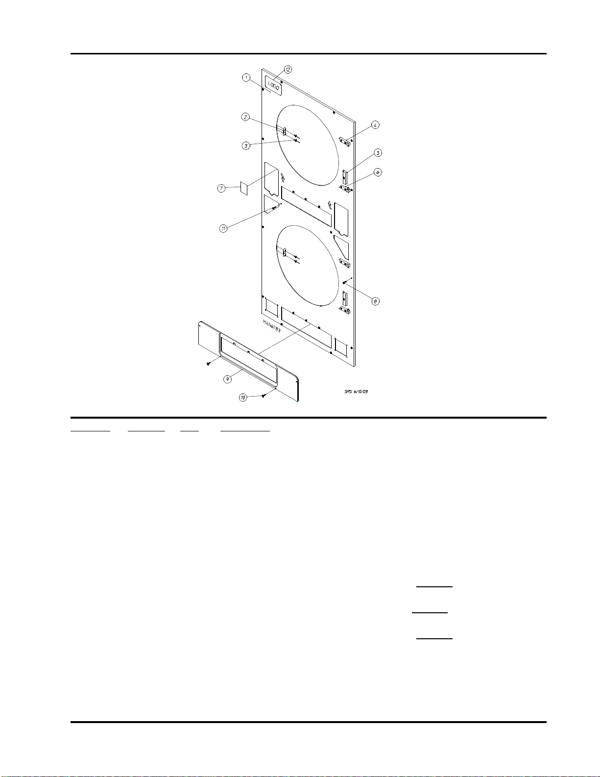
Front Panel Assembly
3
Illus. No. Part No. Qty. Description
1 883144 1 White Right Hand Front Panel Assembly
(includes illus. nos. 1, 2, 3, and 7)
883149 1 Bisque Right Hand Front Panel Assembly
(includes illus. nos. 1, 2, 3, and 7)
883159 1 Stainless Steel Right Hand Front Panel Assembly
(includes illus. nos. 1, 2, 3, and 7)
2 881987 2 Friction Door Latch Kit
(includes illus. nos. 2 and 3)
3 154215 4 5/32 x 1/4” Rivet
4 -------- 1 Top Hinge Block Assembly
(refer to Main Door “Steel” Assembly on page 10)
5 -------- 1 Main Door Switch
(refer to Main Door Switch Assembly on page 11)
6 -------- 1 Bottom Hinge Block Assembly
(refer to Main Door “Steel” Assembly on page 10)
7 354197 2 Arrow Backup Plate
8 150517 10 #10-16 x 1-1/2” Hex Head TEK Screw
9 882798 1 Black Kick Plate
10 150311 2 #10-16 x 3/4” Hex Head TEK Crimptite Screw
11 150309 8 #10-16 x 1/2” Hex Head TEK Screw
12 881053 1 ADC Logo with Adhesive Tape
Telephone: (508) 678-9000 Fax: (508) 678-9447
Page 6
4
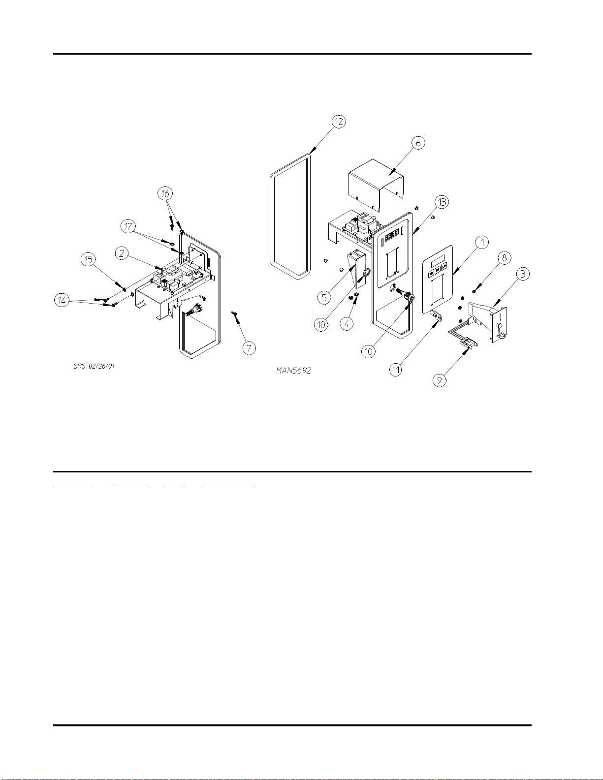
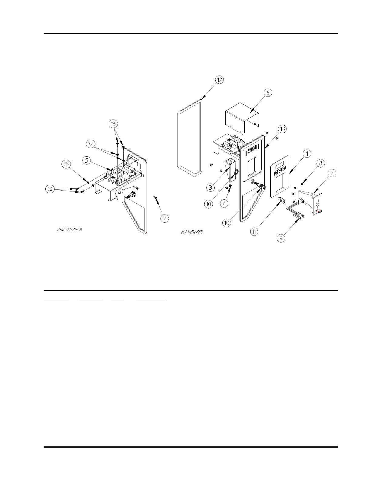
Right Coin Computer Panel Type II
For Models Mfd. as of February 15, 2001
Illus. No. Part No. Qty. Description
1 112574 1 Keyboard (touch pad)
2 137251 1 Computer Board with Display
3 881163 1 25¢ U.S. Hanke Coin Acceptor with Optic Switch
4 151001 2 #8-32 Pal Nut
5 354192 1 Optic Switch Protector
6 354260 1 Computer Cover
7 150201 4 #10-32 x 1/4” Phillips Pan Head Tap Screw
8 150102 4 Hanke Acceptor M3 Metric Hex Nut
9 883067 1 Hanke Optic Switch Assembly
10 182621 1 Control Panel Lock with Key
11 182622 1 Key ONLY (specify key number when ordering)
12 117603 4 1/8” x 9/16” Noise Suppressor Tape
13 883019 1 Right Computer Panel ONLY Type II
14 150005 2 #6-32 x 1/4” Phillips Right Hand Machine Screw
15 153010 2 #6 Star Washer
16 150005 2 #6-32 x 1/4” Phillips Right Hand Machine Screw
17 153010 2 #6 Star Washer
American Dryer Corporation 88 Currant Road / Fall River, MA 02720-4781
Page 7
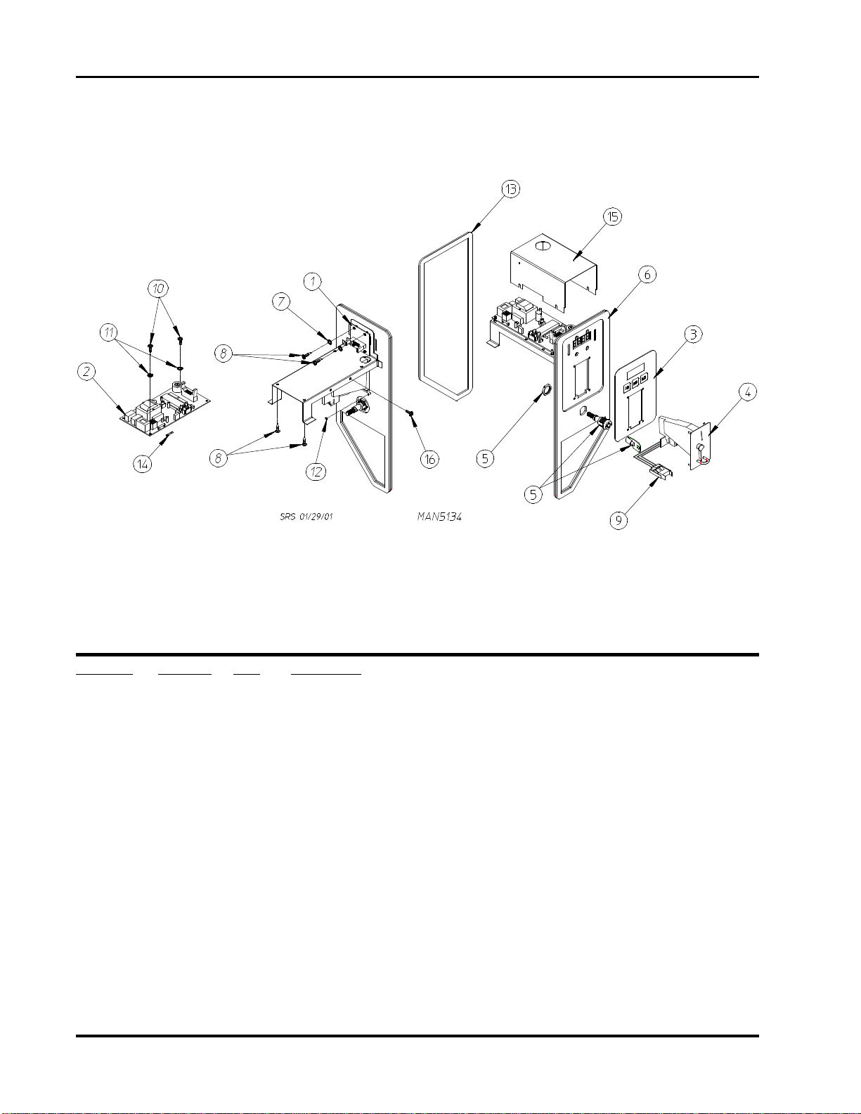
Left Coin Computer Panel Type II
For Models Mfd. as of February 15, 2001
5
Illus. No. Part No. Qty. Description
1 112574 1 Keyboard (touch pad)
2 881163 1 25¢ U.S. Hanke Coin Acceptor with Optic Switch
3 354192 1 Optic Switch Protector
4 151001 2 #8-32 Pal Nut
5 137251 1 Computer Board with Display
6 354260 1 Computer Cover
7 150201 4 #10-32 x 1/4” Phillips Pan Head Tap Screw
8 150102 4 Hanke Acceptor M3 Metric Hex Nut
9 883067 1 Hanke Optic Switch Assembly
10 182621 1 Control Panel Lock with Key
11 182622 1 Key ONLY (specify key number when ordering)
12 117603 4 1/8” x 9/16” Noise Suppressor Tape
13 883018 1 Left Computer Panel ONLY Type II
14 150005 2 #6-32 x 1/4” Phillips Right Hand Machine Screw
15 153010 2 #6 Star Washer
16 150005 2 #6-32 x 1/4” Phillips Right Hand Machine Screw
17 153010 2 #6 Star Washer
Telephone: (508) 678-9000 Fax: (508) 678-9447
Page 8
6
Left Coin/Computer Assembly
For Models Mfd. prior to February 15, 2001
Illus. No. Part No. Qty. Description
1 137098 1 Display Board
2 137139 1 Computer Board
137104 1 Grey Ribbon Cable...Not Illustrated
3 112574 1 Keyboard (touch pad)
4 881163 1 25¢ U.S. Hanke Coin Acceptor with Optic Switch
5 182621 1 Control Panel Lock with Key
182622 1 Key ONLY (specify key number when ordering)
6 882679 1 Left Computer Panel ONLY
7 153010 2 #6 Star Washer
8 150005 2 #6-32 x 1/4” Phillips Round Head Machine Screw
9 881143 1 Hanke Optic Switch Assembly
10 150005 2 #6-32 x 1/4” Phillips Round Head Machine Screw
11 153010 2 #6 Star Washer
12 152102 4 Hanke Acceptor M3 Metric Hex Nut
13 117603 4 1/8” x 9/16” Noise Suppressor Tape
14 136048 1 1/8-amp (Slo-Blo) Fuse ONLY
15 354230 1 Computer Board Cover
16 150301 4 #8-18 x 7/16” Phillips Head TEK Screw
American Dryer Corporation 88 Currant Road / Fall River, MA 02720-4781
Page 9
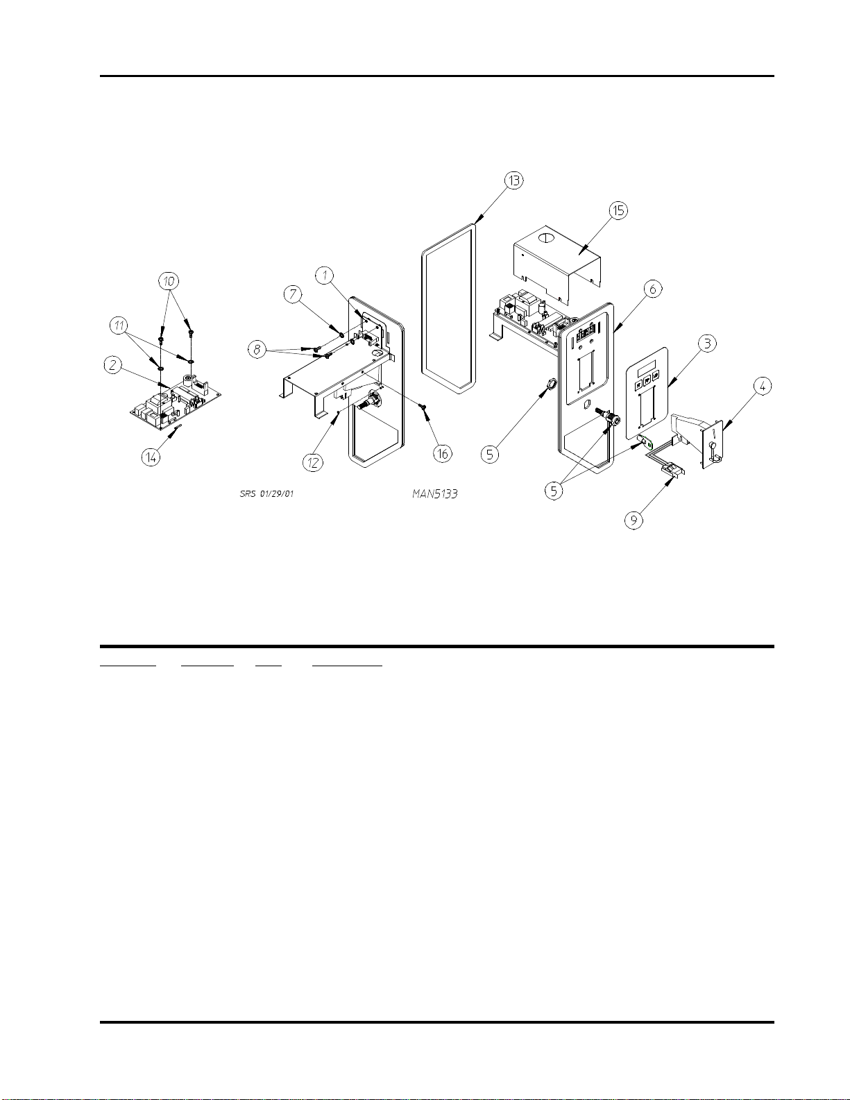
Right Coin/Computer Assembly
For Models Mfd. prior to February 15, 2001
7
Illus. No. Part No. Qty. Description
1 137098 1 Display Board
2 137139 1 Computer Board
137104 1 Grey Ribbon Cable...Not Illustrated
3 112574 1 Keyboard (touch pad)
4 881163 1 25¢ U.S. Hanke Coin Acceptor with Optic Switch
5 182621 1 Control Panel Lock with Key
182622 1 Key ONLY (specify key number when ordering)
6 882936 1 Right Computer Panel ONLY
7 153010 2 #6 Star Washer
8 150005 2 #6-32 x 1/4” Phillips Round Head Machine Screw
9 881143 1 Hanke Optic Switch Assembly
10 150005 2 #6-32 x 1/4” Phillips Round Head Machine Screw
11 153010 2 #6 Star Washer
12 152102 4 Hanke Acceptor M3 Metric Hex Nut
13 117603 4 1/8” x 9/16” Noise Suppressor Tape
14 136048 1 1/8-amp (Slo-Blo) Fuse ONLY
15 354230 1 Computer Board Cover
16 150301 4 #8-18 x 7/16” Phillips Head TEK Screw
Telephone: (508) 678-9000 Fax: (508) 678-9447
Page 10
8
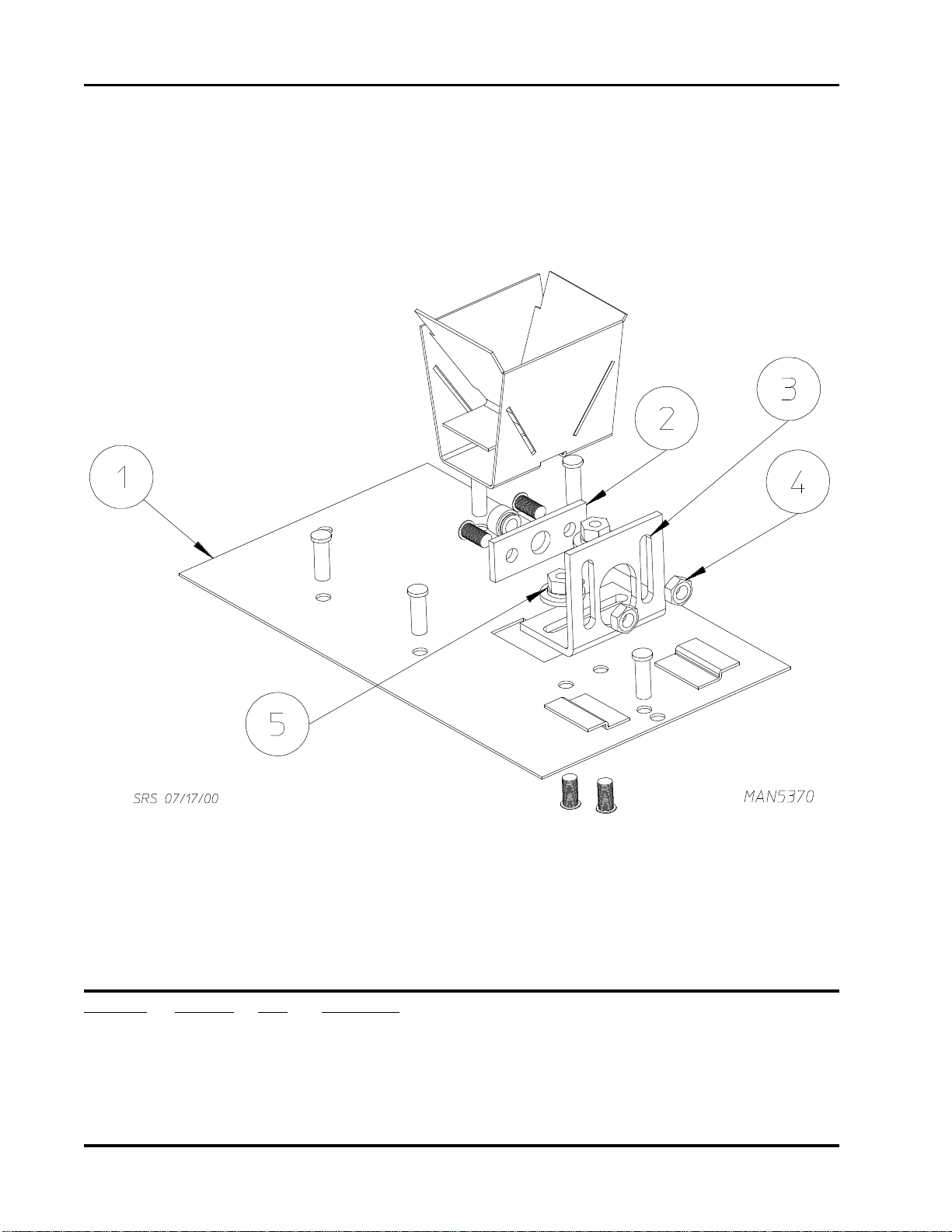
Coin Chute Assembly
Illus. No. Part No. Qty. Description
1 882715 1 Coin Chute
2 882937 1 Control Panel Lock Plate
3 354180 1 Control Panel Lock Bracket
4 152002 2 1/4-20 Hex Nut
5 152014 2 1/4-20 Free Spin Wash Nut
American Dryer Corporation 88 Currant Road / Fall River, MA 02720-4781
Page 11
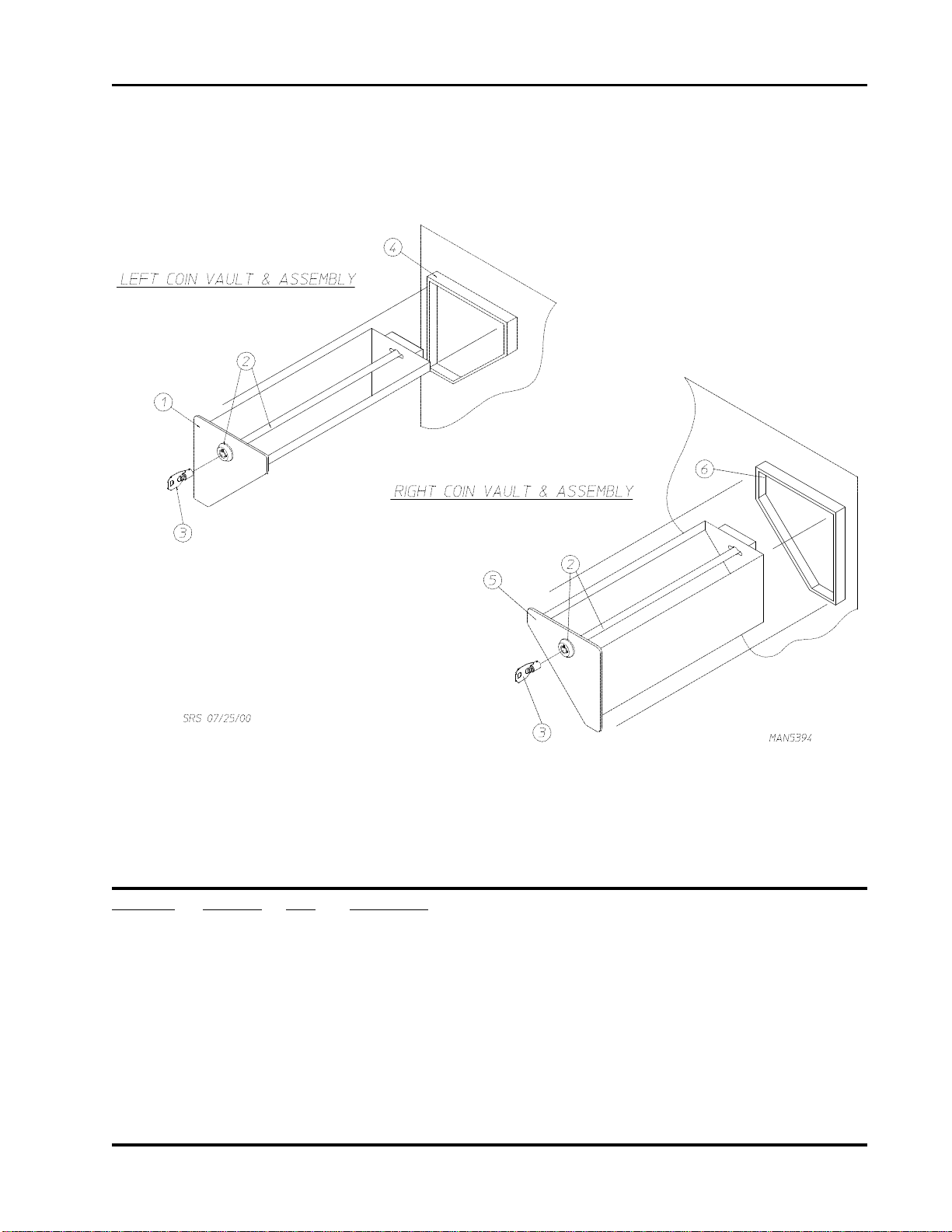
Coin Box/Vault Assembly (Left and Right)
9
Illus. No. Part No. Qty. Description
1 882740 1 Black Left/Right Coin Box Face Plate ONLY
882745 1 Left Coin Box with Black Face Plate (less lock)
2 882672 1 Coin Box Lock Kit (includes 2 locks “keyed alike”)
3 160136* 1 Coin Box Lock Key ONLY
4 882742 1 Black Left Coin Vault ONLY
5 882740 1 Black Left/Right Coin Box Face Plate ONLY
882746 1 Right Coin Box with Black Face Plate (less lock)
6 882741 1 Black Right Coin Vault ONLY
* Specify key number when ordering.
Telephone: (508) 678-9000 Fax: (508) 678-9447
Page 12
10
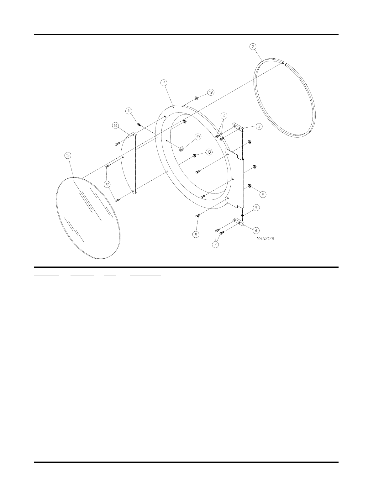
Main Door “Steel” Assembly
Illus. No. Part No. Qty. Description
1 881150 1 Black Main Door Assembly Complete
(includes illus. nos. 1, 2, and 8 through 15)
2 102353 1 Door Gasket
170731 1 Gasket Adhesive (black) 10.3 oz. Cartridge
170730 Gasket Adhesive (clear) 10.3 oz. Cartridge
3 881152 1 Top Hinge Block (black)
(includes illus. nos. 3 and 4)
4 150445 2 1/4-20 x 3/4” Black Cap Head Setscrew
5 153031 1 1/4” Nylon Washer
6 881151 1 Bottom Hinge Block (black)
7 150445 2 1/4-20 x 3/4” Black Cap Head Setscrew
8 150683 3 1/4-20 x 5/8” Carriage Bolt (black)
9 152014 3 1/4-20 Free Spin Wash Nut
10 151010 1 #10-32 Hex Acorn Nut (black)
11 150120 1 Door Latch Screw
12 150683 3 1/4-20 x 5/8” Carriage Bolt (black)
13 152014 3 1/4-20 Free Spin Wash Nut
14 881210 1 Black Main Door Handle ONLY
15 102211 1 #20-7/16” Door Glass
170731 1 Glass Adhesive (black) 10.3 oz. Cartridge
170730 1 Glass Adhesive (clear) 10.3 oz. Cartridge
American Dryer Corporation 88 Currant Road / Fall River, MA 02720-4781
Page 13

Main Door Switch Assembly
11
Illus. No. Part No. Qty. Description
1 153566 2 #6-32 x 7/8” Clinch Stud
2 152013 2 #6-32 Hex Nut
3 153010 2 #6 Star Washer
4 137005 1 Door Switch
5 122636 2 Flag Terminal
6 881211 1 Black Main Door Switch Housing ONLY
881153 1 Black Main Door Switch Housing Complete
(includes illus. nos. 1, 2, 3, 4, and 6)
7 150301 2 #8-18 x 7/16” Phillips Pan Head TEK Screw
Telephone: (508) 678-9000 Fax: (508) 678-9447
Page 14

12
Basket (Tumbler)/Support Assemblies
For Models Mfd. as of December 12, 2000
Illus. No. Part No. Qty. Description
1 154210 40 5/32” x 3/16” Pop Rivet
2 354217 1 Spacer Plate
3 153048 1 Inner Friction Teflon® Pad
4 116332 1 94” x 2-1/2” x 1/8” Felt Collar
5 882765 1 One Arm Basket (Tumbler) Support Assembly
(includes illus. nos. 2, 3, and 5)
6 882766 1 Basket (Tumbler) Assembly for One Arm Basket (Tumbler) Support
(includes illus. nos. 1, 4, and 9)
882990 1 One Arm Basket (Tumbler) and Support Assembly Complete
(includes illus. nos. 1 through 7 and 9)
7 154210 6 5/32” x 3/16” Pop Rivet
8 100191 1 12 Rib 105” Long (J) High Temperature Belt
9 115992 1 Inner Ring Felt Collar
401010 1 #847 Adhesive for Felt Collar (5 oz. tube)
American Dryer Corporation 88 Currant Road / Fall River, MA 02720-4781
Page 15

Basket (Tumbler)/Support Assemblies
For Models Mfd. prior to December 12, 2000
13
Illus. No. Part No. Qty. Description
1 154210 40 5/32” x 3/16” Pop Rivet
2 354217 1 Spacer Plate
3 153048 1 Inner Friction Teflon® Pad
4 116332 1 94” x 2-1/2” x 1/8” Felt Collar
5 882765 1 One Arm Basket (Tumbler) Support Assembly
(includes illus. nos. 2, 3, and 5)
6 882766 1 Basket (Tumbler) Assembly for One Arm Basket (Tumbler) Support
(includes illus. nos. 1, 4, and 12)
882788 1 One Arm Basket (Tumbler) and Support Assembly Complete
(includes illus. nos. 1 through 10 and 12)
7 100918 2 3/8-16 x 26-3/4” Hex Head Tie Rod
8 153004 10 3/8” x 1” Flat Washer
9 153005 2 3/8” Split Lock Washer
10 152005 2 3/8-16 Hex Nut
11 100191 1 12 Rib 105” Long (J) High Temperature Belt
12 115992 1 Inner Ring Felt Collar
401010 1 #847 Adhesive for Felt Collar (5 oz. tube)
Telephone: (508) 678-9000 Fax: (508) 678-9447
Page 16

14
Top Locking Lint Basket Assembly
For Models Mfd. as of July 17, 2000
Illus. No. Part No. Qty. Description
1 115904 1 Lint Basket Felt
2 154210 5 5/32” x 3/16” Pop Rivet
3 160140 1 Key ONLY For XX4451
4 882787 1 Top Locking Lint Basket with Lock (white)
(includes illus. nos. 1 through 5)
882794 1 Top Locking Lint Basket with No Lock (bisque)
(includes illus. nos. 1, 2, and 4)
5 160038 1 Lint Basket Lock with Cam (no key)
160050 1 Lint Basket Lock (no cam and key) For Stainless Steel ONLY
6 117605 4 1/4” x 3/8” Neoprene Sponge Tape (sold by the foot)
American Dryer Corporation 88 Currant Road / Fall River, MA 02720-4781
Page 17

Bottom Locking Lint Basket Assembly
For Models Mfd. as of July 17, 2000
15
Illus. No. Part No. Qty. Description
1 115904 1 Lint Basket Felt
2 154210 5 5/32” x 3/16” Pop Rivet
3 160140 1 Key ONLY For XX4451
4 882797 1 Bottom Locking Lint Basket Assembly with Lock (black)
(includes illus. nos. 1 through 6)
882796 1 Bottom Locking Lint Basket Assembly with No Lock (black)
(includes illus. nos. 1, 2, 4, and 6)
5 160038 1 Lint Basket Lock with Cam (no key)
6 117604 4 1/8” x 3/8” Neoprene Sponge Tape (sold by the foot)
Telephone: (508) 678-9000 Fax: (508) 678-9447
Page 18

16
Top Lint Basket Assembly
For Models Mfd. prior to July 17, 2000
Illus. No. Part No. Qty. Description
1 115904 1 Lint Basket Felt
2 882681 1 White Top Lint Basket Assembly
(includes illus. nos. 1 through 4)
882877 1 Bisque Top Lint Basket Assembly
(includes illus. nos. 1 through 4)
3 154210 5 5/32” x 3/16” Pop Rivet
4 117605 4 1/4” x 3/8” Neoprene Sponge Tape (sold by the foot)
American Dryer Corporation 88 Currant Road / Fall River, MA 02720-4781
Page 19

Bottom Lint Drawer/Basket Assembly with Wide Face
For Models Mfd. prior to July 17, 2000
17
Illus. No. Part No. Qty. Description
1 115904 1 Lint Basket Felt
2 882680 1 Lint Drawer/Basket Assembly Complete
(includes illus. nos. 1 through 3)
3 154210 5 5/32” x 3/16” Pop Rivet
4 117605 6 1/4” x 3/8” Neoprene Sponge Tape (sold by the foot)
Telephone: (508) 678-9000 Fax: (508) 678-9447
Page 20

18
Bottom Lint Basket Assembly without Lock
For Models Mfd. prior to July 17, 2000
Illus. No. Part No. Qty. Description
1 115904 1 Lint Basket Felt
2 882878 1 Black Bottom Lint Basket Assembly
(includes illus. nos. 1 through 4)
3 154210 5 5/32” x 3/16” Pop Rivet
4 117604 4 1/4” x 3/8” Neoprene Sponge Tape (sold by the foot)
American Dryer Corporation 88 Currant Road / Fall River, MA 02720-4781
Page 21

Separator Assembly
19
Illus. No. Part No. Qty. Description
1 152014 18 1/4-20 Free Spin Wash Nut
2 882926 1 Inner Ring Separator Bracket
882717 1 Inner Ring Separator Assembly
(includes illus. nos. 1 through 3)
3 115903 1 Basket (tumbler) Separation Felt
Telephone: (508) 678-9000 Fax: (508) 678-9447
Page 22

20
Rotational Sensor/Sail Switch and Teflon® Backup Washer Plate
Illus. No. Part No. Qty. Description
1 882747 1 Teflon® Backup Washer and Magnet Assembly
(includes illus. nos. 1 through 5)
153047 1 Outer Friction Pad
2 354203 1 Teflon® Backup Washer
3 102102 1 Magnet
4 -------- 1 Inner Teflon® Pad
(refer to Basket Support Assembly on page 12 and page 13)
5 154218 1 1/8” x 3/8” Aluminum Pop Rivet
6 153002 1 5/16” Split Lock Washer
7 150501 1 5/16-18 x 3/4” Tap Bolt
8 882748 1 Sail Switch and Rotational Sensor Bracket
(includes illus. nos. 8, 9, 13, 14, 17, and 18)
9 154004 1 Twin Speed Nut
10 105550 1 Sail Switch Rod
11 154002 1 1/8” Push On Fastener
12 319206 1 Sail Switch Damper
13 122200 1 Sail Switch ONLY
14 150303 2 #4 x 3/4” Pan Head “A” Machine Screw
15 130102 1 190° Rear Basket (tumbler) Hi-Limit
16 150300 2 #10-16 x 1/2” Hex Washer TEK Screw
17 152014 2 1/4-20 Free Spin Wash Nut
18 153528 1 #8-32 x 1/2” Self-Clinching Stud
19 824807 1 Rotational Sensor Magnetic Reed Switch
American Dryer Corporation 88 Currant Road / Fall River, MA 02720-4781
Page 23

Lint Coop and Adjustment Wheel Bracket Assembly
21
Illus. No. Part No. Qty. Description
1 150220 2 3/8-24 Hex Nut
2 122002 1 Lint Drawer Switch
3 150309 2 #10-16 x 1/2” Hex Head TEK Crimptite Screw
4 882927 1 Lint Coop ONLY
882716 1 Lint Coop Assembly Complete
(includes illus. nos. 1 through 8)
5 152014 4 1/4-20 Free Spin Wash Nut
6 154210 20 5/32” x 3/16” Pop Rivet
7 354067 1 Adjustment Wheel Bracket
883119 1 Adjustment Wheel Bracket Assembly Complete
(includes illus. nos. 1, 7, and 8)
8 882799 2 Thruster Wheel
(includes illus. nos. 1 and 8)
Telephone: (508) 678-9000 Fax: (508) 678-9447
Page 24

22
Left Rear Wheel Bracket (3-Bolt)
For Models Mfd. as of October 17, 2000
Illus. No. Part No. Qty. Description
1 150220 1 3/8-24 Hex Nut
2 150510 2 1/4-20 x 3/4” Hex Head Machine Bolt
3 153007 2 1/4” Split Lock Washer
4 883004 1 Left Rear Roller Wheel Bracket ONLY (3-bolt)
883125 1 Left Rear Roller Wheel Bracket Assembly with Hardware (3-bolt)
5 882799 1 Thruster Wheel
American Dryer Corporation 88 Currant Road / Fall River, MA 02720-4781
Page 25

Right Rear Wheel Bracket (3-Bolt)
For Models Mfd. as of October 17, 2000
23
Illus. No. Part No. Qty. Description
1 883005 1 Right Rear Roller Wheel Bracket ONLY (3-bolt)
883126 1 Right Rear Roller Wheel Bracket Assembly with Hardware (3-bolt)
2 150220 1 3/8-24 Hex Nut
3 150510 3 1/4-20 x 3/4” Hex Head Machine Bolt
4 153007 3 1/4” Split Lock Washer
5 882799 1 Thruster Wheel
Telephone: (508) 678-9000 Fax: (508) 678-9447
Page 26

24
Rear Thruster Wheel Bracket Assembly
For Models Mfd. prior to October 17, 2000
Illus. No. Part No. Qty. Description
1 150220 1 3/8-24 Hex Nut
2 150510 2 1/4-20 x 3/4” Hex Head Machine Bolt
3 153007 2 1/4” Split Lock Washer
4 883006 1 2-Bolt Rear Wheel Box Type Bracket ONLY
883104 1 2-Bolt Rear Wheel Box Type Bracket Assembly with Hardware
5 882799 1 Thruster Wheel
American Dryer Corporation 88 Currant Road / Fall River, MA 02720-4781
Page 27

Microprocessor Temperature Sensor Bracket Assembly
25
Illus. No. Part No. Qty. Description
1 882682 1 Temperature Sensor Bracket Assembly Complete
(includes illus. nos. 1 through 6 and 9 through 12)
354117 1 Sensor Bracket ONLY
2 883025 1 Microprocessor Temperature Sensor Probe Assembly Complete
(includes illus. nos. 2 through 6)
3 154007 1 1/4” Push On Fastener
4 121028 2 1/4” Terminal
5 122701 4 Socket Terminal ONLY
122801 Pins/Socket Extraction Tool
6 122605 1 4-Position Connector (female)
7 122700 4 Pin Terminal ONLY
8 122604 1 4-Position Connector (male)
9 130119 1 190° Automatic Thermostat
10 150005 2 #6-32 x 1/4” Phillips Round Head Machine Screw
11 153010 2 #6 Star Washer
12 152013 2 #6-32 Hex Nut
13 152014 2 1/4-20 Free Spin Wash Nut
Telephone: (508) 678-9000 Fax: (508) 678-9447
Page 28

26
Blower Motor Assembly
Illus. No. Part No. Qty. Description
1 181038 1 1/4 HP 115/230v/60 Hz Blower Motor
2 100604 1 12-1/2” Impellor with 1/2” Bore
3 153050 4 1/2” x 1-1/16” Flat Washer
4 152006 2 1/2-20 Left Hand Jam Nut
5 100731 1 1/8” x 3/32” x 1-1/8” Key
6 153007 4 1/4” Split Lock Washer
7 153001 4 5/16” Flat Washer
8 153002 4 5/16” Split Lock Washer
9 152004 4 5/16-18 Hex Nut
10 154279 4 5/16-18 x 3/4” Carriage Bolt
11 117604 4 1/8” x 3/8” Neoprene Sponge Tape (sold by the foot)
12 150111 4 1/4-20 x 1/2” Phillips Round Head Machine Screw
13 882922 1 Blower Motor Mount ONLY
882714 1 Blower Motor and Mount Assembly Complete
(includes illus. nos. 1 through 13)
American Dryer Corporation 88 Currant Road / Fall River, MA 02720-4781
Page 29

Rear Electrical Panel
27
Illus. No. Part No. Qty. Description
1 150301 4 #8-18 x 7/16” Phillips Pan Head TEK Screw
2 141403 1 Transformer - 24 VAC
881763 1 Termination Kit
3 882928 1 Rear Electrical Panel with Stud
4 136049 1 3/4-amp Slo-Blo Fuse (fuse 1)
5 136008 2 Fuse Holder
6 136106 1 2-amp Slo-Blo Fuse (fuse 2)
7 152002 1 1/4-20 Hex Nut
8 153021 1 1/4” Star Washer
9 121010 1 Ground Lug
10 824828 1 R.C. Network Assembly
11 132475 1 Double-Pole Contactor - 24 VAC
12 150103 2 #8-32 x 3/4” Phillips Round Head Screw
13 120714 1 Quick Connect Power Block
14 151001 2 #8-32 Pal Nut
15 112075 1 “Ground Here” Label
16 112025 1 “Caution” Label
17 150297 1 Green Ground Screw
18 114103 1 “Electric Service Connection” Label
19 121012 1 Ground Lug
20 150299 2 #10 x 1” Hex Washer TEK Screw
Telephone: (508) 678-9000 Fax: (508) 678-9447
Page 30

28
Top Burner Box Assembly
American Dryer Corporation 88 Currant Road / Fall River, MA 02720-4781
Page 31

Top Burner Box Assembly
Illus. No. Part No. Qty. Description
1 141138 1 Burner Manifold
2 143277 1 1/4” x 1/8” 90° Brass Elbow
3 141137 2 Stainless Steel Burner Tube
4 128927 1 1/2” 24 VAC (natural gas) Gas Valve
880960 1 1/2” 24 VAC Liquid Propane (L.P.) Gas Valve
140411 1 1/2” Liquid Propane (L.P.) Conversion Kit (per basket [tumbler])
882635* Liquid Propane (L.P.) Conversion Kit
(includes parts to convert both top and bottom basket [tumbler] to liquid
propane [L.P.] gas)
5 354141 1 Gas Valve Mounting Bracket
6 142710 1 3/4” x 4” Black Nipple
7 354146 2 Burner Bottom Baffle
8 130400 1 290° Burner Hi-Limit
9 354162 1 Direct Spark Ignition (DSI) Module Mounting Panel
10 354163 1 Pipe Bracket
11 354170 1 Burner Tube Hood
12 142505 1 3/4” x 1/2” x 1/2” Tee
13 142700 1 1/2” Close Nipple
14 128935 1 Direct Spark Ignition (DSI) Module with Three (3) Tries
15 143100 1 1/4” Aluminum Tubing
16 150299 2 #10 x 1” Hex Washer TEK Screw
17 353222 1 Manifold Bracket
18 150300 10 #10-16 x 1/2” Hex Washer TEK Screw
19 140819 2 #30 Burner Orifice (natural gas)
20 154210 30 5/32” x 3/16” Pop Rivet
21 882907 1 Direct Spark Ignition (DSI) Ignitor/Flame-Probe
with High Voltage (HV) Wire
883031 1 High Voltage (HV) Ignition Cable with Socket Terminal
22 143259 1 Bulkhead Fitting
23 142601 1 3/4” Black Union
24 882906 1 Burner Box ONLY
882949** 1 Natural Gas Burner Assembly Complete (less orifice)
25 -------- 1 Rear Electrical Panel Assembly Complete
(refer to Rear Electrical Panel on page 27)
29
* Consult factory for elevations over 2,000 feet.
** Burner orifice is not included and must be ordered separately.
Telephone: (508) 678-9000 Fax: (508) 678-9447
Page 32

30
Bottom Burner Box Assembly
American Dryer Corporation 88 Currant Road / Fall River, MA 02720-4781
Page 33

Bottom Burner Box Assembly
Illus. No. Part No. Qty. Description
1 143100 1 1/4” Aluminum Tubing
2 141138 1 Burner Manifold
3 141137 2 Stainless Steel Burner Tube
4 128927 1 1/2” 24 VAC (natural gas) Gas Valve
880960 1 1/2” Liquid Propane (L.P.) Gas Valve Conversion Kit
(per basket [tumbler])
140411 1 1/2” Liquid Propane (L.P.) Conversion Kit
882635* Liquid Propane (L.P.) Conversion Kit
(includes parts to convert both top and bottom basket [tumbler] to liquid
propane [L.P.] gas)
5 354141 1 Gas Valve Mounting Bracket
6 143118 1 60” Stainless Steel Flex Hose 1/2” x 1/2”
7 354146 2 Burner Bottom Baffle
8 143277 1 1/4” x 1/8” 90° Brass Elbow
9 128935 1 Direct Spark Ignition (DSI) Module with Three (3) Tries
10 354162 1 Direct Spark Ignition (DSI) Module Mounting Panel
11 354163 1 Pipe Bracket
12 354170 1 Burner Tube Hood
13 142506 1 1/2” x 1/2” Street Elbow
14 130400 1 290° Burner Hi-Limit
15 150299 2 #10 x 1” Hex Washer TEK Screw
16 150300 10 #10-16 x 1/2” Hex Washer TEK Screw
17 353222 1 Manifold Pipe Bracket
18 140819 2 #30 Burner Orifice (natural gas)
19 154210 30 5/32” x 3/16” Pop Rivet
20 143259 1 Bulkhead Fitting
21 882906 1 Burner Box ONLY
882949** 1 Natural Gas Burner Assembly Complete (less orifice)
22 --------- 1 Rear Electrical Panel Assembly Complete
(refer to Rear Electrical Panel on page 27)
23 882907 1 Direct Spark Ignition (DSI) Ignitor/Flame-Probe
with High Voltage (HV) Wire
883031 1 High Voltage (HV) Ignition Cable with Socket Terminal
31
* Consult factory for elevations over 2,000 feet.
** Burner orifice is not included and must be ordered separately.
Telephone: (508) 678-9000 Fax: (508) 678-9447
Page 34

32
Drive Motor/Motor Mount Assemblies
Illus. No. Part No. Qty. Description
1 154279 4 5/16-18 x 3/4” Carriage Bolt
2 154277 1 3/8” x 1/2” Shoulder Screw
3 154274 1 3/8-16 x 2” Long Spade Bolt
4 154276 1 1/4-20 x 5/16” x 5/8” Shoulder Bolt
5 157010 1 1-7/8” Extension Spring
6 100250 1 Idler Wheel
7 153002 4 5/16” Split Lock Washer
8 152004 4 5/16-18 Hex Nut
9 121350 1 Bronze Bushing
10 150508 4 3/8-16 x 3/4” Hex Head Machine Bolt
11 152005 2 3/8-16 Hex Nut
12 150600 1 3/8-16 x 1-1/2” Tap Bolt
13 153004 4 3/8” x 1” Flat Washer
14 153005 5 3/8” Split Lock Washer
15 153001 5 5/16” Flat Washer
16 882720 1 Motor Mount ONLY
17 882687 1 Drive Motor and Sheave Assembly ONLY
882997 1 Drive Motor Sheave ONLY
883069 1 Drive Motor Sheave With Setscrew
(for models mfd. as of March 14, 2001)
170733 * Retaining Compound
18 882767 1 Idler Arm Assembly with Hardware
(includes illus. nos. 2, 6 through 10, 16 and 17)
882929 1 Idler Arm ONLY
* As required.
American Dryer Corporation 88 Currant Road / Fall River, MA 02720-4781
Page 35

Exhaust Duct Assembly
33
Illus. No. Part No. Qty. Description
1 354078 2 Exhaust Access Plate
2 150309 12 #10-16 x 1/2” Hex Head TEK Crimptite Screw
3 354171 2 Harness Stiffener
4 150103 4 #8-32 x 3/4” Phillips Round Head Machine Screw
5 151001 4 #8-32 Pal Nut
6 154210 158 5/32” x 3/16” Pop Rivet
7 -------- 2 Blower Motor Assembly
(refer to Blower Motor Assembly on page 26)
8 143557 1 12” Exhaust Adapter
Telephone: (508) 678-9000 Fax: (508) 678-9447
Page 36

34
Rear Back Guard Assembly
Illus. No. Part No. Qty. Description
1 103500 4 Leveling Leg
2 882948 2 Back Guard
883070 2 Back Guard Short
(for models mfd. as of April 24, 2001)
3 150300 12 #10-16 x 1/2” Hex Washer TEK Screw
4 883071 1 Top Pocket Flex Gas Line Bracket
5 883072 1 Bottom Pocket Flex Gas Line Pivot Support
883029 1 Top And Bottom Gas Line Bracket Kit
(for models mfd. prior to April 24, 2001)
6 883073 1 Rear Left Side Pane Support Assembly
7 143118 1 60” Stainless Steel Flex Hose
American Dryer Corporation 88 Currant Road / Fall River, MA 02720-4781
Page 37

Wrapper Gasket
35
Illus. No. Part No. Qty. Description
1 102310* 4 Wrapper Gasket
(for models mfd. as of April 19, 2001)
* Sold by the foot.
Telephone: (508) 678-9000 Fax: (508) 678-9447
Page 38

ADC 450344 7 - 05/19/04 - 1
 Loading...