

Page 1
AD-410 Phase 7
Parts Manual
American Dryer Corporation
88 Currant Road
Fall River MA 02720-4781
T elephone: (508) 678-9000 / Fax: (508) 678-9447
E-mail: techsupport_large_dryer@amdry.com
www .amdry .com
ADC Part No. 450033
Page 2

Retain This Manual In A Safe Place For Future Reference
American Dryer Corporation products embody advanced concepts in engineering, design, and safety. If this product is
properly maintained, it will provide many years of safe, efficient, and trouble-free operation.
ONLY qualified technicians should service this equipment.
OBSERVE ALL SAFETY PRECAUTIONS displayed on the equipment or specified in the installation manual included with
the dryer.
The following “FOR YOUR SAFETY” caution must be posted near the dryer in a prominent location.
FOR YOUR SAFETY
Do not store or use gasoline or
other flammable vapors or liquids
in the vicinity of this or any other
appliance.
W e have tried to make this manual as complete as possible and hope you will find it useful. ADC reserves the right to make
changes from time to time, without notice or obligation, in prices, specifications, colors, and material, and to change or
discontinue models.
POUR VOTRE SÉCURITÉ
Ne pas entreposer ni utiliser d’essence
ni d’autres vapeurs ou liquides
inflammables dans le voisinage de cet
appareil ou de autre appareil.
Important
For your convenience, log the following information:
DATE OF PURCHASE ____________________________ MODEL NO. __________________________________________
RESELLER’S NAME _______________________________________________________________________________________
Serial Number(s) ________________________________________________________________________________________
________________________________________________________________________________________
AD-410
________________________________________________________________________________________
Replacement parts can be obtained from your reseller or the ADC factory. When ordering replacement parts from the factory ,
you can FAX your order to ADC at (508) 678-9447 or telephone your order directly to the ADC Parts Department at
(508) 678-9000. Please specify the dryer model number and serial number in addition to the description and part number, so
that your order is processed accurately and promptly.
The illustrations on the following pages may not depict your particular dryer exactly. The illustrations are a composite of the
various dryer models. Be sure to check the descriptions of the parts thoroughly before ordering.
“IMPORT ANT NOTE TO PURCHASER”
Information must be obtained from your local gas supplier on the instructions
to be followed if the user smells gas. These instructions must be posted in a
prominent location near the dryer.
Page 3

Table of Contents
Solid Back Panel Assembly
1 Door Models................................................................................................................................. 3
Front/Rear Panel Assembly Automatic/Manual Door ........................................................................... 4, 5
Left Manual Load Door Assembly ...................................................................................................... 6, 7
Right Manual Load Door Assembly ..................................................................................................... 8, 9
Left Automatic Load Door Assembly .............................................................................................. 10, 11
Right Automatic Load Door Assembly............................................................................................. 12, 13
End of Cycle Light Assembly ................................................................................................................ 14
Automatic Door Pneumatics Assembly .................................................................................................. 15
Magnetic Door Switch Assembly .......................................................................................................... 16
Left Control Door Assembly
For 1 Door or 2 Door Models ........................................................................................................ 17
Front Control Door Assembly......................................................................................................... 18, 19
Right Rear Control Door Assembly
2 Door Models Only ................................................................................................................ 20, 21
Left Hand Electrical Control Panel Assembly
For Models Mfd. with Thermal-Magnetic Protection Only ......................................................... 22, 23
Right Hand Electrical Control Panel................................................................................................. 24, 25
Base Main Electrical Junction Box Assembly
For Models Mfd. with Thermal-Magnetic Protection Only ......................................................... 26, 27
Basket (Tumbler) and Idler Shaft Assembly ........................................................................................... 28
Basket (Tumbler) Retaining Wheel Mount Assembly .............................................................................. 29
Lint Basket Assembly ........................................................................................................................... 30
T emperature Sensor Bracket Assembly ................................................................................................. 31
Basket (Tumbler) Drive Shaft Assembly .......................................................................................... 32, 33
Tilt Switch Assembly ............................................................................................................................. 34
Tilt Piston Mount Assembly ................................................................................................................... 35
Post Assembly ...................................................................................................................................... 36
Drive Motor Assembly.......................................................................................................................... 37
Front Burner Box Assembly .................................................................................................................. 38
Page 4

Rear Burner Box Assembly ................................................................................................................... 39
Sail Switch Assembly...................................................................................................................... 40, 41
Fan Motor Assembly ...................................................................................................................... 42, 43
Air Jet Assembly................................................................................................................................... 44
Direct Spark Ignition (DSI) Module Assembly....................................................................................... 45
Gas Piping Assembly ...................................................................................................................... 46, 47
Steam Coil Assembly ...................................................................................................................... 48, 49
Tilting Steam Piping Assembly ......................................................................................................... 50, 51
Pneumatic V alve Assembly
1 Auto Door/2-W ay Tilt w/Optional Sprinkler ........................................................................... 52, 53
Pneumatic V alve Assembly
2 Auto Doors/1-W ay Tilt w/Optional Sprinkler.......................................................................... 54, 55
Sprinkler Option Control Panel Assembly........................................................................................ 56, 57
Optional Sprinkler Assembly........................................................................................................... 58, 59
Side Panel Assemblies .................................................................................................................... 60, 61
Guard Assemblies
2-W a y T ilt ................................................................................................................................ 62, 63
Optional Sprinkler T emperature Probe Junction Box Assembly .............................................................. 64
Front Base and Front T op Panel Assemblies.......................................................................................... 65
Selector Switch, Nameplate, and Mounting Base Chart ......................................................................... 66
Right Rear/Front Control Panel Charts .................................................................................................. 67
Right Hand Electrical Control Panel Chart ............................................................................................. 68
Right Hand and Left Hand Base Electrical Panel Charts ......................................................................... 69
Page 5
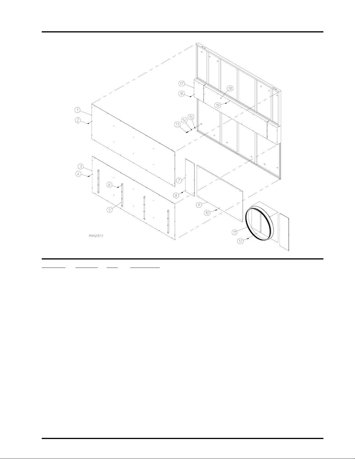
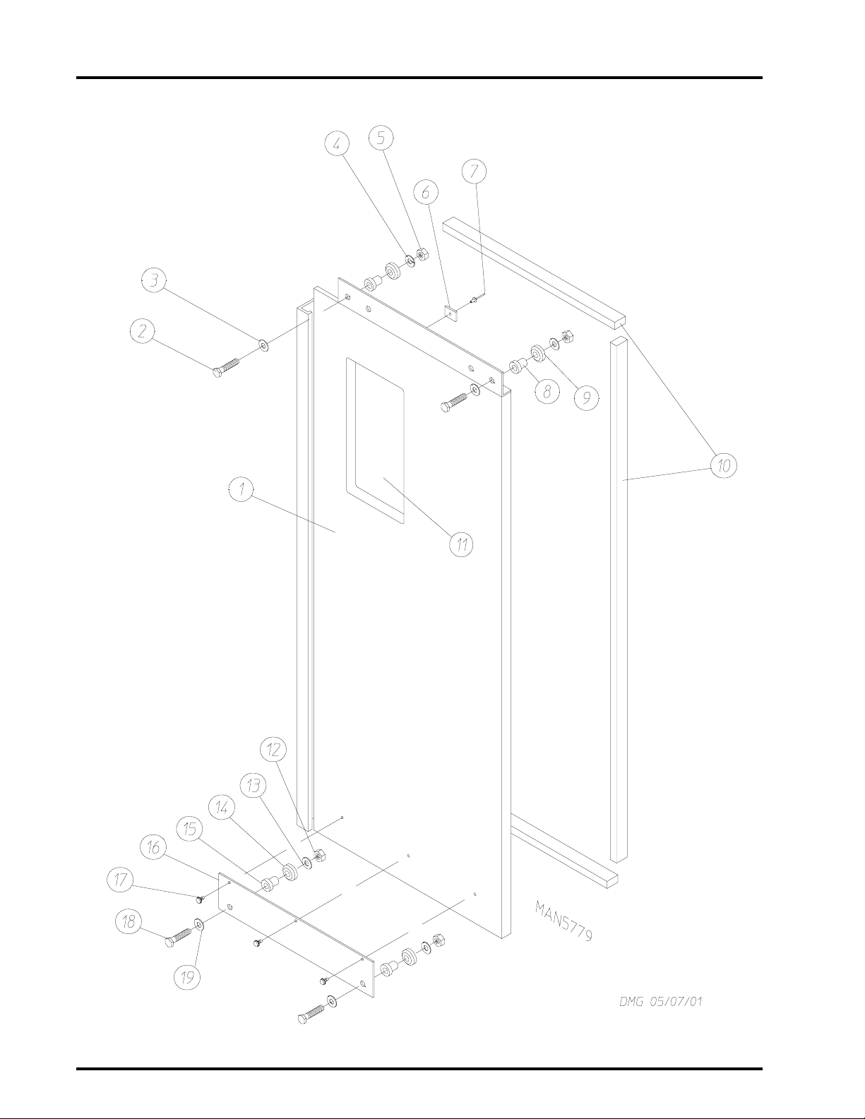
Solid Back Panel Assembly
1 Door Models
3
Illus. No. Part No. Qty. Description
1* 334615 1 Solid Back Panel Top Cover
2 150522 26 1/4-20 x 1/2” Hex Head TEK Screw
3* 334616 1 Solid Back Panel Bottom Cover
4 150522 26 1/4-20 x 1/2” Hex Head TEK Screw
5 170344 4 Nylon Back Guide
6 150311 12 #10 x 3/4” Hex Head Crimptite Screw
7* 334542 2 Piston Cover
8 150309 12 #10-16 x 1/2” Hex Head TEK Crimptite Screw
9* 334541 1 Rear Left Base Panel
10 150522 6 1/4-20 x 1/2” Hex Head TEK Screw
11 * 814069 1 Transition Piece (1 door dryer Only)
12 150522 6 1/4-20 x 1/2” Hex Head TEK Screw
13 150617 12 3/8-16 x 1” Hex Head Machine Bolt
14 153005 12 3/8” Split Lock Washer
15 153004 12 3/8” Flat Washer
16 150522 12 1/4-20 x 1/2” Hex Head TEK Screw
17* 334521 2 Solid Back Panel Wheel Cover
18* 334520 1 Solid Back Panel Center Cover
19 150522 14 1/4-20 x 1/2” Hex Head TEK Screw
* Specify color when ordering.
Telephone: (508) 678-9000 Fax: (508) 678-9447
Page 6
4
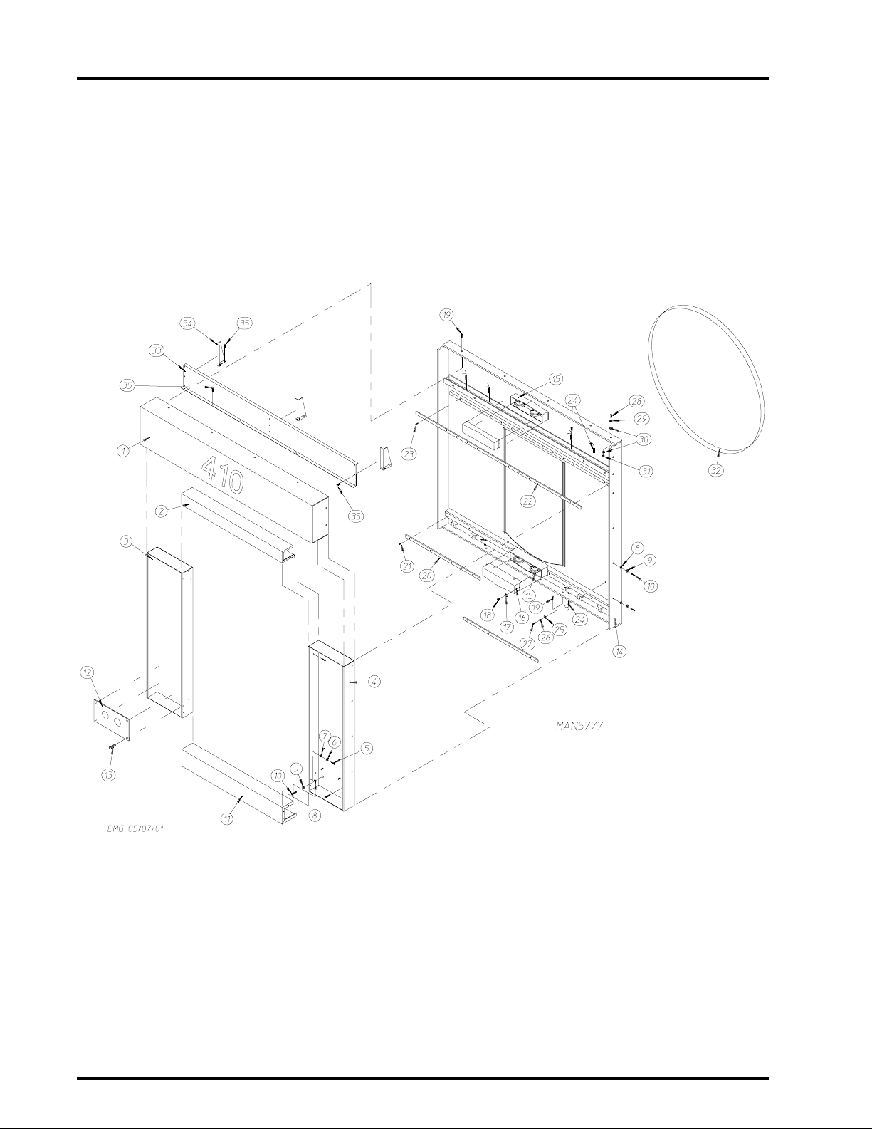
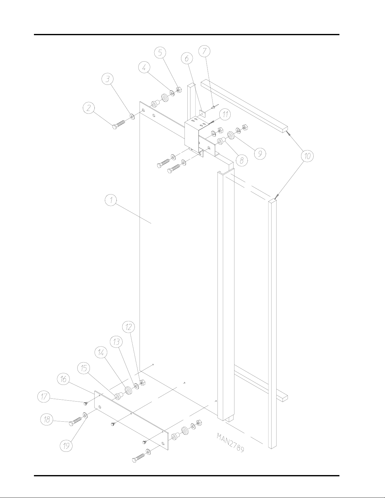
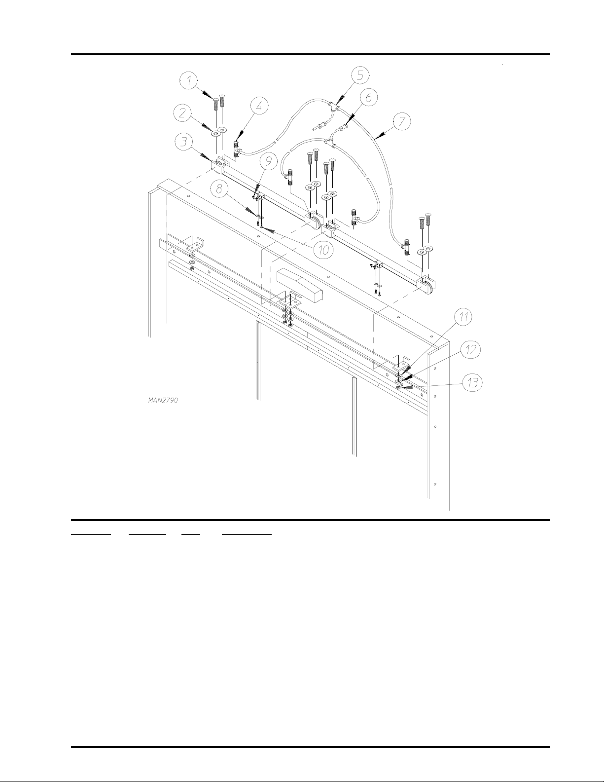
Front/Rear Panel Assembly Automatic/Manual Door
NOTE: Same assembly used as rear panel assembly for 2 door models.
American Dryer Corporation 88 Currant Road / Fall River, MA 02720-4781
Page 7

Front/Rear Panel Assembly Automatic/Manual Door
Illus. No. Part No. Qty. Description
1* 814059 1 Upper Guard
2* 814058 1 Middle Guard
3* 881388 1 Left Control Cabinet
4* 881387 1 Right Control Cabinet
5 150510 6 1/4-20 x 3/4” Hex Head Machine Bolt
6 153007 6 1/4” Lock Washer
7 153018 6 1/4” Flat Washer
8 153001 10 5/16” Flat Washer
9 153002 10 5/16” Lock Washer
10 150501 10 5/16-18 x 3/4” Hex Head Machine Bolt
11 * 814057 1 Bottom Guard
12 332938 1 Feed Thru Plate
13 150309 4 #10-16 x 1/2” Hex Head TEK Crimptite Screw
14 881386 1 Front Panel Assembly
15 --------- 4 Retaining Wheel Assembly (refer to Basket [Tumbler] Retaining Wheel
Mount Assembly on
16 814070 2 Retaining Wheel Cover
17 153018 4 1/4” Flat Washer
18 150309 4 #10-16 x 1/2” Hex Head TEK Crimptite Screw
19 150523 10 1/4-20 x 3/4” Hex Washer Machine Bolt
20 170362 2 Bottom Door Track
21 154312 14 #10-32 x 3/4” Socket Head Cap Screw
22 170363 1 Upper Door Track
23 154312 16 #10-32 x 3/4” Socket Head Cap Screw
24 880783 4 Door Switch Assembly
25 153004 12 3/8” Flat Washer
26 153005 12 3/8” Split Lock Washer
27 150617 12 3/8-16 x 1” Hex Head Machine Bolt
28 150605 4 1/2-13 x 1-1/2” Hex Head Bolt
29 153026 4 1/2” Lock Washer
30 153050 8 1/2 x 1/16 Flat Washer
31 152011 4 1/2-13 Hex Nut
32 116009 1 200” x 1-3/8” Felt Basket (tumbler)
33 334546 1 Top Front Panel
34 332680 3 Left Gusset for Top Front Panel
35 150522 6 1/4-20 x 1/2” TEK Screw
page 29)
5
* Specify color when ordering.
NOTE: Same assembly used as rear panel assembly for 2 door models.
Telephone: (508) 678-9000 Fax: (508) 678-9447
Page 8
6
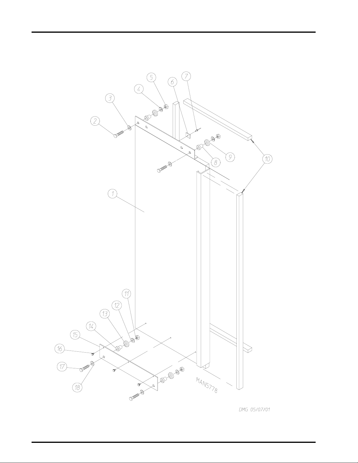
Left Manual Load Door Assembly
American Dryer Corporation 88 Currant Road / Fall River, MA 02720-4781
Page 9

Left Manual Load Door Assembly
Illus. No. Part No. Qty. Description
1* 881392 1 Left Automatic Load Door Assembly Complete
(includes illus. nos. 1 through 11)
881391 1 Left Automatic Load Door ONLY
2 150112 3 1/4-20 x 1-1/4” Hex Head Machine Screw
3 153018 3 1/4” Flat Washer
4 153007 3 1/4” Lock Washer
5 152002 3 1/4-20 Hex Nut
6 102102 1 Magnet
7 154200 1 5/32” Pop Rivet
8 170367 2 Stainless Steel Stationary Bushing
9 170366 2 Stainless Steel Sealed Wheel
10 115995 80” Steam Damper Gasket (sold by the inch)
11 152002 2 1/4-20 Hex Nut
12 153007 2 1/4” Lock Washer
13 170366 2 Stainless Steel Sealed Wheel
14 170367 2 Stainless Steel Stationary Bushing
15* 334558 1 Lower Trolley ONLY
16 150301 3 #8-18 x 7/16” Phillips Pan Head TEK Screw
17 150112 2 1/4-20 x 1-1/4” Hex Head Machine Screw
18 153018 2 1/4” Flat Washer
7
* Specify color when ordering.
Telephone: (508) 678-9000 Fax: (508) 678-9447
Page 10
8
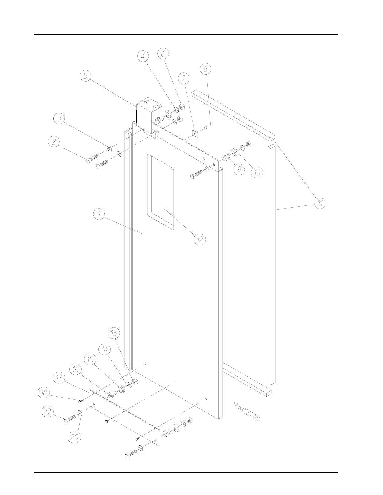
Right Manual Load Door Assembly
American Dryer Corporation 88 Currant Road / Fall River, MA 02720-4781
Page 11

Right Manual Load Door Assembly
Illus. No. Part No. Qty. Description
1* 881390 1 Right Automatic Load Door Assembly Complete
(includes illus. nos. 1 through 12)
881389 1 Right Automatic Load Door ONLY
2 150112 3 1/4-20 x 1-1/4” Hex Head Machine Screw
3 153018 3 1/4” Flat Washer
4 153007 3 1/4” Lock Washer
5 152002 3 1/4-20 Hex Nut
6 102102 1 Magnet
7 154200 1 5/32” Pop Rivet
8 170367 2 Stainless Steel Stationary Bushing
9 170366 2 Stainless Steel Sealed Wheel
10 115995 80” Steam Damper Gasket (sold by the inch)
11 102215 1 Glass W indow
170730 1 Glass Adhesive (10.3 oz. cartridge)
12 152002 2 1/4-20 Hex Nut
13 153007 2 1/4” Lock Washer
14 170366 2 Stainless Steel Sealed Wheel
15 170367 2 Stainless Steel Stationary Bushing
16* 334558 1 Lower Trolley ONLY
17 150301 3 #8-18 x 7/16” Phillips Pan Head TEK Screw
18 150112 2 1/4-20 x 1-1/4” Hex Head Machine Screw
19 153018 2 1/4” Flat Washer
9
* Specify color when ordering.
Telephone: (508) 678-9000 Fax: (508) 678-9447
Page 12
10
Left Automatic Load Door Assembly
American Dryer Corporation 88 Currant Road / Fall River, MA 02720-4781
Page 13

Left Automatic Load Door Assembly
Illus. No. Part No. Qty. Description
1* 881392 1 Left Automatic Load Door Assembly Complete
(includes illus. nos. 1 through 11)
881391 1 Left Automatic Load Door ONLY
2 150112 3 1/4-20 x 1-1/4” Hex Head Machine Screw
3 153018 3 1/4” Flat Washer
4 153007 3 1/4” Lock Washer
5 152002 3 1/4-20 Hex Nut
6 102102 1 Magnet
7 154200 1 5/32” Pop Rivet
8 170367 2 Stainless Steel Stationary Bushing
9 170366 2 Stainless Steel Sealed Wheel
10 115995 80” Steam Damper Gasket (sold by the inch)
11 334134 1 Automatic Door Bracket
12 152002 2 1/4-20 Hex Nut
13 153007 2 1/4” Lock Washer
14 170366 2 Stainless Steel Sealed Wheel
15 170367 2 Stainless Steel Stationary Bushing
16* 334558 1 Lower Trolley ONLY
17 150301 3 #8-18 x 7/16” Phillips Pan Head TEK Screw
18 150112 2 1/4-20 x 1-1/4” Hex Head Machine Screw
19 153018 2 1/4” Flat Washer
11
* Specify color when ordering.
Telephone: (508) 678-9000 Fax: (508) 678-9447
Page 14
12
Right Automatic Load Door Assembly
American Dryer Corporation 88 Currant Road / Fall River, MA 02720-4781
Page 15

Right Automatic Load Door Assembly
Illus. No. Part No. Qty. Description
1* 881390 1 Right Automatic Load Door Assembly Complete
(includes illus. nos. 1 through 12)
881389 1 Right Automatic Load Door ONLY
2 150112 3 1/4-20 x 1-1/4” Hex Head Machine Screw
3 153018 3 1/4” Flat Washer
4 153007 3 1/4” Lock Washer
5 334134 1 Automatic Door Bracket
6 152002 3 1/4-20 Hex Nut
7 102102 1 Magnet
8 154200 1 5/32” Pop Rivet
9 170367 2 Stainless Steel Stationary Bushing
10 170366 2 Stainless Steel Sealed Wheel
1 1 115995 80” Steam Damper Gasket (sold by the inch)
12 102215 1 Glass W indow
170730 1 Glass Adhesive (10.3 oz. cartridge)
13 152002 2 1/4-20 Hex Nut
14 153007 2 1/4” Lock Washer
15 170366 2 Stainless Steel Sealed Wheel
16 170367 2 Stainless Steel Stationary Bushing
17* 334558 1 Lower Trolley ONLY
18 150301 3 #8-18 x 7/16” Phillips Pan Head TEK Screw
19 150112 2 1/4-20 x 1-1/4” Hex Head Machine Screw
20 153018 2 1/4” Flat Washer
13
* Specify color when ordering.
Telephone: (508) 678-9000 Fax: (508) 678-9447
Page 16
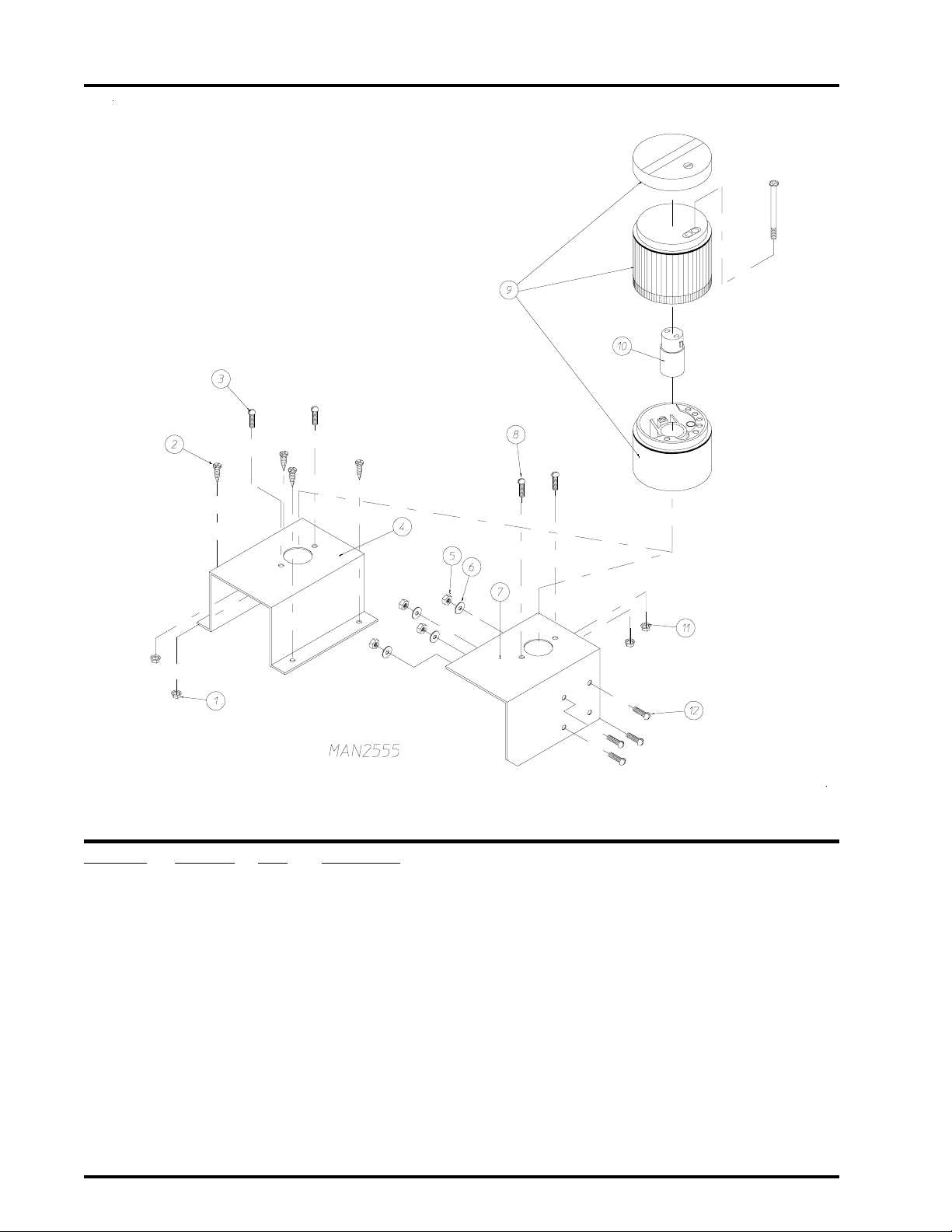
14
End of Cycle Light Assembly
Illus. No. Part No. Qty. Description
1 151001 2 #8-32 Pal Nut
2 150415 4 #10-16 x 1/2” Phillips Round Head Crimptite Screw
3 150108 2 #8-32 x 1/2” Slotted Head Machine Screw
4* 821480 1 Cycle Light Bracket (for steam models Only)
5 152001 4 #8-32 Hex Nut
6 153012 4 #8 Star Washer
7* 332850 1 Cycle Light Bracket (for gas models Only)
8 150108 2 #8-32 x 1/2” Slotted Head Machine Screw
9 123222 1 “Orange” Cycle Light
10 123221 1 Bulb - 24 VAC
1 1 151001 2 #8-32 Pal Nut
12 150108 4 #8-32 x 1/2” Slotted Head Machine Screw
* Specify color when ordering.
American Dryer Corporation 88 Currant Road / Fall River, MA 02720-4781
Page 17
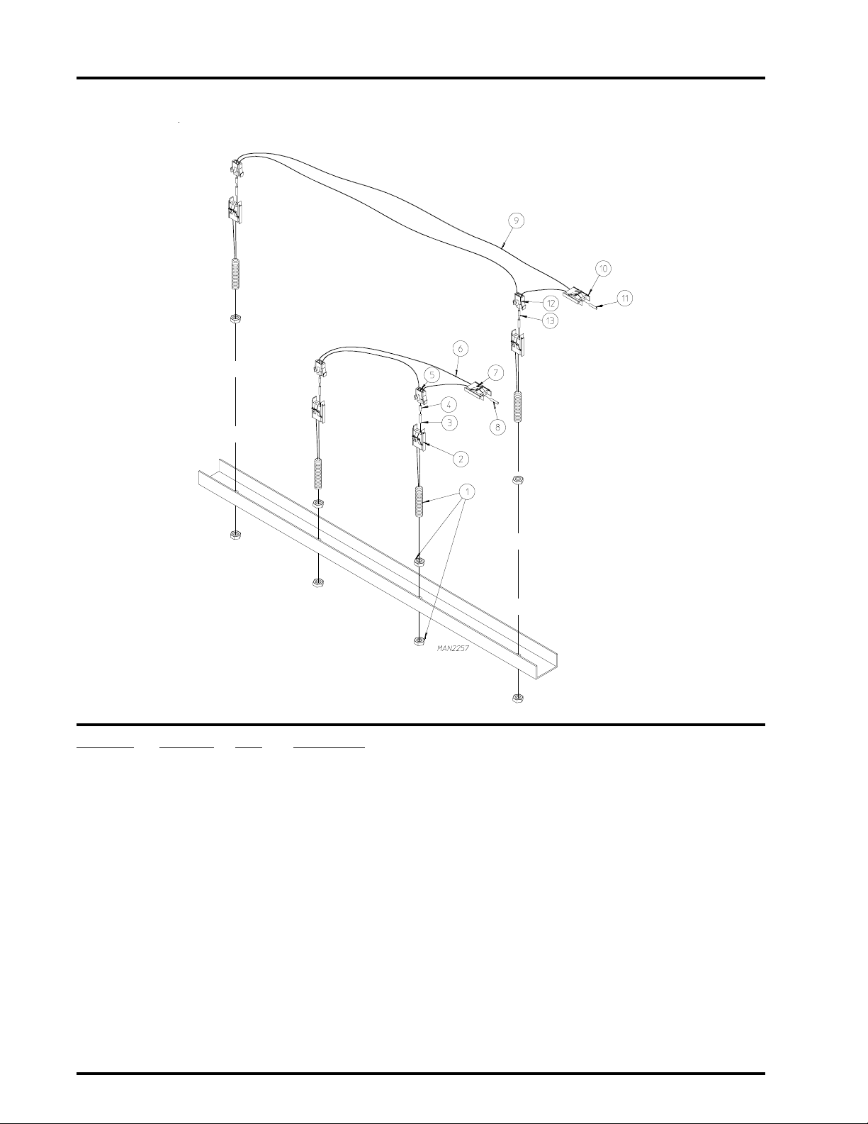
Automatic Door Pneumatics Assembly
15
Illus. No. Part No. Qty. Description
1 150308 8 #8-32 x 2-1/2” Long Machine Screw
2 153000 8 #8 Flat Washer
3 100432 2 Cable Cylinder
4 128978 4 1/8” N.P.T. x 1/4” Tube Flow Control
5 143156 2 1/4” Poly Tee
6 143154 2 1/4 ” B r a ss Poly Connector
7 143110 * 1/4” Poly-Flo T ubing (sold by the foot)
8 153012 4 #8 Star Washer
9 152001 4 #8-32 Hex Nut
10 150103 4 #8-32 x 3/4” Phillips Head Machine Screw
11 153000 8 #8 Flat Washer
12 153012 8 #8 Star Washer
13 152001 8 #8-32 Hex Nut
* As required.
Telephone: (508) 678-9000 Fax: (508) 678-9447
Page 18
16
Magnetic Door Switch Assembly
Illus. No. Part No. Qty. Description
1 826514 4 Magnetic Door Switch Assembly with Nuts
(includes illus. nos. 1 through 3)
2 122598 1 2-Pin Connector (male)
3 137028 2 Pin
4 137021 4 Microprocessor Socket
5 122599 2 2-Pin Socket Connector (female)
6 881240 1 Door Switch “Closed Position” Harness
(includes illus. nos. 4 through 8)
7 122598 1 2-Pin Connector (male)
8 137028 2 Pin
9 881241 1 Door Switch “Open Position” Harness
(includes illus. nos. 9 through 13)
10 122598 1 2-Pin Connector (male)
1 1 137028 2 Pin
12 122599 2 2-Pin Socket Connector (female)
13 137021 4 Microprocessor Socket
American Dryer Corporation 88 Currant Road / Fall River, MA 02720-4781
Page 19
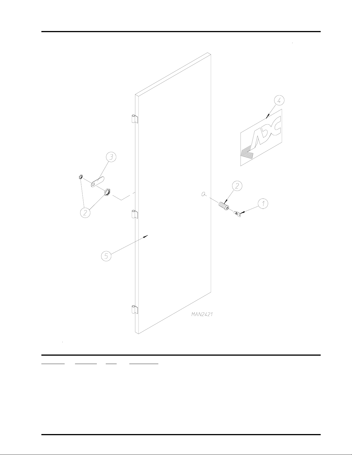
Left Control Door Assembly
For 1 Door or 2 Door Models
17
Illus. No. Part No. Qty. Description
1 160140 1 ACE® XX4451 Key ONLY
2 160050 1 ACE® Control Door Lock ONLY Less Key (keyed to #XX4451)
3 160014 1 Cam ONLY
4 112360 1 ADC Logo ONLY (tape kit not included)
870011 1 Logo Double T ape Kit
5* 821334 1 Left Hand Control Door
* Specify color when ordering.
Telephone: (508) 678-9000 Fax: (508) 678-9447
Page 20
18
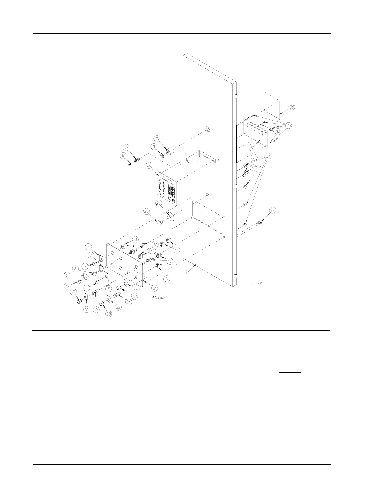
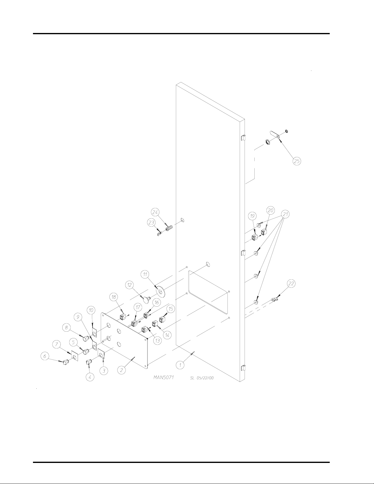
Front Contr ol Door Assembly
Illus. No. Part No. Qty. Description
1 821597 1 Front Right Control Door ONLY
2 --------- 1 Front Right Control Door Panel ONL Y
(refer to Right Rear/Front Control Panel Charts on page 67)
3 122438 1 Load/Dry/Unload Nameplate
4 122361 1 3-Position Maintained Operator
5 123203 1 Black Push Button Operator
6 122415 1 Nameplate “Forward”
7 122416 1 Nameplate “Reverse”
8 123202 1 White Push Button Operator
9 122413 1 Tilt Off T ilt On Nameplate
10 122360 1 2-Position Maintained Operator
1 1 132396 2 Mounting Base with Normally Opened (N.O.) and Normally Closed (N.C.)
Contact Block
12 132394 2 Mounting Base with Normally Opened (N.O.) Contact Block
American Dryer Corporation 88 Currant Road / Fall River, MA 02720-4781
Page 21

Front Control Door Assembly (continued)
Illus. No. Part No. Qty. Description
13 132386 1 Normally Opened (N.O.) Contact Block
14 132387 4 Normally Closed (N.C.) Contact Block
15 123201 1 Green Lighted Push Button Operator
16 122410 1 Engraved Nameplate: ON
17 123212 1 24 Volt Lamp
18 132388 2 Normally Opened (N.O.) Contact Block with Direct Supply
19 132395 1 Mounting Base with Normally Closed (N.C.) Contact Block
20 122421 1 Engraved Nameplate: OFF
21 123204 1 Red Push Button Operator
22 122420 1 Sprinkler Stop Nameplate
23 123200 1 Amber Lighted Push Button Operator
24 123212 1 24 Volt Lamp
25 122351 1 “EMERGENCY STOP” (E-Stop) Operator
26 122419 1 Engraved “EMERGENCY STOP” (E-Stop) Label
27 121509 6 Tie Wrap Clips
28 112571 1 Phase 7 Keyboard (touch pad)
29 134018 1 Alarm Horn Volume Control
30 128967 1 80-90 Decibel Panel Mount Alarm Horn
31 152014 4 1/4-20 with 3/4” Free Spin Wash Nut
32 132395 1 Mounting Base with Normally Closed (N.C.) Contact Block
33 132387 1 Normally Closed (N.C.) Contact Block
34 153010 4 #6 Star Washer
35 150005 4 #6-32 x 1/4” Phillips Round Head Machine Screw
36 122426 1 Caution Label
37 882896 1 Phase 7 Display Board
(for models mfd. as of October 2000)
882894 1 Phase 7 Microprocessor Control Computer
(for models mfd. prior to October 2000)
38 160140 1 ACE
39 160050 1 ACE® Control Door Lock Less Key (keyed to #XX4451)
®
XX4451 Key ONLY
19
Telephone: (508) 678-9000 Fax: (508) 678-9447
Page 22
20
Right Rear Control Door Assembly
2 Door Models ONLY
American Dryer Corporation 88 Currant Road / Fall River, MA 02720-4781
Page 23

Right Rear Control Door Assembly
2 Door Models ONLY
Illus. No. Part No. Qty. Description
1 814364 1 Right Rear Control Door ONLY
2 --------- 1 Right Rear Door Control Panel
(refer to Right Rear/Front Control Panel Charts on page 67)
3 122438 1 Load/Dry/Unload Nameplate
4 122361 1 3-Position Maintained Operator
5 123202 1 White Push Button Operator
6 122360 1 2-Position Maintained Operator
7 122413 1 Tilt Off T ilt On Nameplate
8 123203 1 Black Push Button Operator
9 122416 1 Nameplate “Reverse”
10 122415 1 Nameplate “Forward”
11 122419 1 “EMERGENCY STOP” (E-Stop) Label
12 122351 1 “EMERGENCY STOP” (E-Stop) Operator
13 132394 1 Mounting Base with Normally Opened (N.O.) Contact Block
14 132386 1 Normally Opened (N.O.) Contact Block
15 132387 2 Normally Closed (N.C.) Contact Block
16 132394 1 Mounting Base with Normally Opened (N.O.) Contact Block
17 132396 1 Mounting Base with Normally Opened (N.O.) and Normally Closed
(N.C.) Contact Block
18 132396 1 Mounting Base with Normally Opened (N.O.) and Normally Closed
(N.C.) Contact Block
19 132395 1 Mounting Base with Normally Closed (N.C.) Contact Block
20 132387 1 Normally Closed (N.C.) Contact Block
21 152014 4 1/4-20 with 3/4” Free Spin Wash Nut
22 121509 6 Tie Wrap Clips
23 160140 1 ACE® XX4451 Key ONLY
24 160050 1 ACE® Control Door Lock Less Key (keyed to #XX4451)
25 160014 1 Cam ONLY
21
Telephone: (508) 678-9000 Fax: (508) 678-9447
Page 24

22
Left Hand Electrical Control Panel Assembly
For Models Mfd. with Thermal-Magnetic Protection ONLY
American Dryer Corporation 88 Currant Road / Fall River, MA 02720-4781
Page 25

Left Hand Electrical Control Panel Assembly
For Models Mfd. with Thermal-Magnetic Protection ONLY
Illus. No. Part No. Qty. Description
1 334269 1 Left Hand Electrical Panel
832677 1 Left Hand Electrical Panel Assembly Complete
(includes illus. nos. 1 through 20)
2 112075 1 Ground Label
3 114007 1 Danger High Voltage Label
4 -------- 1 Auxiliary Contact Block For Gas and Steam Models
(refer to Chart For Left Hand Base Electrical Panel on
5 -------- 1 Manual Starter/Thermal-Magnetic Breaker For Gas and Steam Models
(refer to Chart For Left Hand Base Electrical Panel on page 69)
6 -------- 1 Reversing Contactor For Gas and Steam Models
(refer to Chart For Left Hand Base Electrical Panel on page 69)
7 132437 2 Varistor
8 120768 8 35 x 15mm Din Mounting Rail
9 150300 2 #10-16 x 1/2” Hex Washer TEK Screw
10 120768 3 35 x 15mm Din Mounting Rail
11 150300 2 #10-16 x 1/2” Hex Washer TEK Screw
12 132494 1 Sprinkler Contactor (for dryer with sprinkler option Only)
13 120768 2 35 x 15mm Din Mounting Rail
14 150300 2 #10-16 x 1/2” Hex Washer TEK Screw
15 120765 2 Standard End Stop
16 -------- 1 2-Pole Circuit Breaker For Gas and Steam Models
(refer to Chart For Left Hand Base Electrical Panel on page 69)
17 120727 1 Ground T erminal Block
18 150300 1 #10-16 x 1/2” Hex Washer TEK Screw
19 120770 2 End Bracket 12mm
20 120768 4 35 x 15mm Din Mounting Rail
page 69)
23
Telephone: (508) 678-9000 Fax: (508) 678-9447
Page 26

24
Right Hand Electrical Control Panel
Illus. No. Part No. Qty. Description
1 821833 1 Front Right Electrical Panel ONLY
2 150334 4 3/8” Flat Washer
3 153005 4 3/8” Split Lock Washer
4 152005 4 3/8-16 Hex Nut
5 121422 28” 1” Wireway Cover (sold by the inch)
6 121430 28” 1” x 3” Slotted W all Wire Duct
7 121422 31” 1” Wireway Cover (sold by the inch)
8 121430 31” 1” x 3” Slotted W all Wire Duct
9 121422 12” 1” Wireway Cover (sold by the inch)
10 121430 12” 1” x 3” Slotted W all Wire Duct
1 1 120777 10 2-Position Terminal Block Jumper
12 120771 4 2-Position Gray Line Block
13 120776 6 Small Insulator For 2-Position Block
14 120778 2 4-Position Gray Line Block
15 120801 2 Large Insulator For 4-Position Block
American Dryer Corporation 88 Currant Road / Fall River, MA 02720-4781
Page 27

Right Hand Electrical Control Panel (continued)
Illus. No. Part No. Qty. Description
16 ------- 1 Circuit Breaker #7
(refer to Right Hand Electrical Control Panel Chart on page 68)
17 ------- 1 Circuit Breaker #6
18 120773 3 2-Position Green/Y ellow Ground Block
19 120772 2 2-Position Blue Neutral Block
20 120765 2 Standard End Stop
21 120768 6 35 x 15mm Din Mounting Rail
22 150300 3 #10-16 x 1/2” Hex Washer TEK Screw
23 122424 1 Power Warning Label
24 150300 4 #10-16 x 1/2” Hex Washer TEK Screw
25 --------- 1 Transformer Assembly
(refer to Right Hand Electrical Control Panel Chart on page 68)
26 882895 1 Phase 7 Input/Output (I/O) Board
(for models mfd. as of October 2000)
882894 1 Phase 7 Microprocessor Control Computer
(for models mfd. prior to October 2000)
27 120768 28 35 x 15mm Din Mounting Rail
28 120765 2 Standard End Stop
29 882892 1 Auto Door TSX 07 PLC
882893 1 Main Manual Door TSX 07 PLC
30 150005 4 #6-32 x 1/4” Phillips Round Head Machine Screw
31 153010 4 #6 Star Washer
32 150300 4 #10-16 x 1/2” Hex Washer TEK Screw
33 120768 12” 35 x 15mm Din Mounting Rail
34 120765 2 Standard End Stop
35 120776 1 Small Insulator For 2-Position Block
36 120771 21 2-Position Gray Line Block
37 120801 4 Large Insulator For 4-Position Block
38 120778 13 4-Position Gray Line Block
39 120773 3 2-Position Green/Y ellow Ground Block
40 120772 1 2-Position Blue Neutral Block
41 401024 4 Marking T ags
42 120768 12” 35 x 15mm Din Mounting Rail
43 120776 1 Small Insulator For 2-Position Block
44 120773 1 2-Position Green/Y ellow Ground Block
45 120765 2 Standard End Stop
46 120801 7 Large Insulator For 4-Position Terminal Block
47 120778 32 4-Position Gray Line Block
48 120779 3 4-Position Blue Neutral Block
49 120771 9 2-Position Gray Line Block
50 120805 10 4-Position T erminal Block Jumper
51 401024 4 Marking T ags
52 136109 1 2-Amp 250v (fast acting) Fuse
53 136016 1 5-Amp 250v (fast acting) Fuse
25
Telephone: (508) 678-9000 Fax: (508) 678-9447
Page 28

26
Base Main Electrical Junction Box Assembly
For Models Mfd. with Thermal-Magnetic Protection ONLY
American Dryer Corporation 88 Currant Road / Fall River, MA 02720-4781
Page 29

Base Main Electrical Junction Box Assembly
For Models Mfd. with Thermal-Magnetic Protection ONLY
Illus. No. Part No. Qty. Description
1 120770 2 End Bracket 12mm
2 120760 3 T erminal Block
3 131957 1 Circuit Breaker #4 (25-40 amp manual starter)
4 -------- 1 Auxiliary Contact Block
(refer to Chart For Right Hand Base Electrical Panel on
5 -------- 1 Manual Starter
(refer to Chart For Right Hand Base Electrical Panel on page 69)
6 -------- 1 Auxiliary Contact Block
(refer to Chart For Right Hand Base Electrical Panel on
7 114007 1 Danger High Voltage Label
8 120727 2 Ground T erminal Block
9 120768 8 35 x 15mm Din Mounting Rail
10 150300 4 #10-16 x 1/2” Hex Washer TEK Screw
11 120750 1 Ground T erminal Block (for sprinkler option)
12 120758 2 Feed Thru T erminal Block
13 120765 2 Standard End Stop
14 -------- 1 Varistor
(refer to Chart For Right Hand Base Electrical Panel on
15 -------- 1 Contactor
(refer to Chart For Right Hand Base Electrical Panel on page 69)
16 120768 8 35 x 15mm Din Mounting Rail
17 150300 4 #10-16 x 1/2” Hex Washer TEK Screw
18 331499 1 Panel ONLY
19 112075 1 Ground Here Label
27
page 69)
page 69)
page 69)
Telephone: (508) 678-9000 Fax: (508) 678-9447
Page 30

28
Basket (T umbler) and Idler Shaft Assembly
Illus. No. Part No. Qty. Description
1 814068 1 Basket (tumbler) Assembly
814746 1 Removable Perforated Basket (tumbler) Assembly
814747 1 Removable Perforated Panel
2 820600 2 Drive Wheel Assembly
3 1011 9 1 2 2” Bore Split Taper Bushing
4 170511 2 1/8-27 N.P.T. Grease Fitting
5 150627 4 5/8-11 x 5” Hex Head Bolt
6 153016 4 5/8” Flat Washer
7 880882 2 2” Pillow Block Bearing
8 152011 2 1/2-13 Hex Nut
9 153026 2 1/2” Lock Washer
10 150629 2 1/2-13 x 3-1/2” Long Full Thread Bolt
1 1 153016 4 5/8” Flat Washer
12 153015 4 5/8” Lock Washer
13 152010 4 5/8-11 Hex Nut
14 334578 1 Idler Shaft
15 100712 2 1/2” x 1/2” x 3” Long Key
16 102102 2 Magnet
17 154200 2 5/32” Pop Rivet
18 333163 1 Magnet Plate for Rotational Sensor
19 333152 1 Phase 7 Rotational Sensor Bracket
20 150309 1 #10-16 x 1/2” Hex Head Crimptite TEK
21 882633 1 Rotational Sensor Proximity Switch
American Dryer Corporation 88 Currant Road / Fall River, MA 02720-4781
Page 31

Basket (T umbler) Retaining Wheel Mount Assembly
29
Illus. No. Part No. Qty. Description
1 152005 2 3/8-16 Hex Nut
2 153005 2 3/8” Split Lock Washer
3 820566 2 Retaining Wheel Assembly
4 153062 4 Spherical Washer
5 153004 2 3/8” Flat Washer
6 150438 2 3/8-16 x 3-1/4” Long Bolt
Telephone: (508) 678-9000 Fax: (508) 678-9447
Page 32

30
Lint Basket Assembly
Illus. No. Part No. Qty. Description
1* 802107 1 Stainless Steel Lint Draw Assembly
(includes illus nos. 1 and 2)
2 117602 7 Noise Suppressor Tape (sold by the foot)
3 122116 1 Lint Drawer Switch ONLY
4 122605 2 4-Pin Socket Connector (female)
5 122701 4 Socket Terminal ONLY
122801 1 Pin/Socket Extraction T ool (not illustrated)
6 800264 1 Lint Drawer Switch Box Assembly Complete
(includes illus. nos. 4 through 7)
320003 1 Lint Drawer Switch Box ONLY
7 150301 4 #8-18 x 7/16” Phillips Pan Head TEK Screw
8 122700 4 Pin T erminal ONLY
9 122604 2 4-Pin Connector ONLY
10 150301 2 #8-18 x 7/16” Phillips Pan Head TEK Screw
* Specify color when ordering.
American Dryer Corporation 88 Currant Road / Fall River, MA 02720-4781
Page 33

T emperatur e Sensor Bracket Assembly
31
Illus. No. Part No. Qty. Description
1 814008 1 Sensor Bracket Assembly
814009 1 Sensor Bracket Assembly Complete
(includes illus. nos. 1 through 10)
2 150000 2 #6-32 x 1/4” Slotted Round Head Machine Screw
3 153010 2 #6 Star Washer
4 130112 1 225° Thermostat ONLY
5 152000 2 #6-32 Hex Nut
6 121028 2 1/4” x 0.032 Insulated Terminal
7 122701 4 Socket Terminal ONLY
8 122605 1 4-Pin Socket Connector (female)
9 154007 2 1/4” Push On Fastener
10 880251 1 1/4” Temperature Sensor Probe Assembly
(includes illus. nos. 6 through 10)
11 150301 4 #8-18 x 7/16” Phillips Pan Head TEK Screw
Telephone: (508) 678-9000 Fax: (508) 678-9447
Page 34

32
Basket (T umbler) Drive Shaft Assembly
American Dryer Corporation 88 Currant Road / Fall River, MA 02720-4781
Page 35

Basket (T umbler) Drive Shaft Assembly
Illus. No. Part No. Qty. Description
1 820600 2 Drive Wheel Assembly with Hub
2 100712 2 1/2” x 1/2” x 3” Key
3 331760 2 Bearing Mount
4 880882 2 2” Pillow Block Bearing with Setscrews and Grease Fitting
5 153016 4 5/8” Flat Washer
6 150627 4 5/8-11 x 5” Hex Head Bolt
7 153016 2 5/8” Flat Washer
8 153015 4 5/8” Lock Washer
9 152010 4 5/8-11 Hex Nut
10 101022 1 2” Bore Tapered Bushing
11 101019 1 Taper Bushed Speed Reducer
12 154395 1 Gear Reducer Turnbuckle
13 150508 2 3/8-16 x 3/4” Hex Head Machine Bolt
14 153005 2 3/8” Lock Washer
15 153004 2 3/8” Flat Washer
16 101176 1 2B x 5.6 Pulley
17* 100118 2 5L-310 V -Belt
(for models mfd. as of August 14, 2000)
For 60 Hz Models ONLY
100143 2 A29 V-Belt (basket [tumbler] to drive motor)
For 60 Hz Models ONLY
(for models mfd. prior to August 14, 2000)
100119 2 5L-320 V -Belt
For 50 Hz Models ONLY
(for models mfd. as of August 14, 2000)
100138 2 A30 V-Belt (basket [tumbler] to drive motor)
For 50 Hz Models ONLY
(for models mfd. prior to August 14, 2000)
18 100709 1 3/8” x 3/8” x 2” Key
19 101196 1 SDS x 1-5/8” Bushing with Setscrew
20 346510 1 2” x 79-1/16” Drive Shaft
21 332838 2 Basket (tumbler) Bearing Spacer
22 150629 2 1/2-13 x 3-1/2” Hex Head Bolt
23 153026 2 1/2” Lock Washer
24 152011 2 1/2-13 Hex Nut
25 101191 2 2” Bore Tapered Bushing
26 101171 2 Lock Collar - 2” Bore
27 101025 1 Fulcrum
33
* Replace in matched sets (both belts).
Telephone: (508) 678-9000 Fax: (508) 678-9447
Page 36

34
T ilt Switch Assembly
Illus. No. Part No. Qty. Description
1 881252 1 Tilt Switch Assembly Complete
(includes illus. nos. 1, 2, and 4)
122365 1 Limit Switch Rotary Head ONLY
2 122369 1 Tilt Switch Arm
3 150211 4 #10-32 x 2” Phillips Pan Head Machine Screw
4 122367 1 Tilt Switch Body
5 153009 4 #10 Star Washer
6 152008 4 #10-32 Hex Nut
7 150309 4 #10-16 x 1/2” Hex Head TEK Crimptite Screw
8 332794 1 Tilt Switch Bracket
NOTE: One assembly for 1-way tilt models. T wo assemblies for 2-way tilt models.
American Dryer Corporation 88 Currant Road / Fall River, MA 02720-4781
Page 37

Tilt Piston Mount Assembly
35
Illus. No. Part No. Qty. Description
1 100562 1 Piston (5” Bore, 15” Stroke)
2 143283 1 3/8” Poly x 3/8” M.P.T. Straight Connector
3 143221 1 3/8” Poly Tee (brass)
4 143120 20 3/8” Poly Tubing (sold by the foot)
5 143213 1 3/8” Poly x 3/8” Elbow Brass
6 334309 2 Cylinder Pin Nylon Bumper
7 150435 4 3/8-16 x 3” Socket Head Cap Screw
8 100553 1 Rod Eye
9 154315 2 1/4-20 x 1” Socket Head Setscrew
10 331543 1 1” Diameter Pin
11 150599 4 1/4-20 x 1-1/4” Hex Head Machine Bolt
12 153026 4 1/2” Lock Washer
13 153011 4 9/16” I.D. Flat Washer
14 881 170 1 Clevis Assembly
Telephone: (508) 678-9000 Fax: (508) 678-9447
Page 38

36
Post Assembly
Illus. No. Part No. Qty. Description
1 100487 1 3/4” Diameter Pin with Cotter Pin
2 881529 1 Post Assembly
3 100553 1 Rod Eye
4 154315 2 1/4-20 x 1” Socket Head Setscrew
5 334309 2 Cylinder Pin Nylon Bumper
6 150435 4 3/8-16 x 3” Socket Head Cap Screw
7 331543 1 1” Diameter Pin
8 150599 4 1/2-20 x 1-1/8” Hex Head Bolt
9 153026 4 1/2” Lock Washer
10 881 170 1 Clevis Assembly
American Dryer Corporation 88 Currant Road / Fall River, MA 02720-4781
Page 39

Drive Motor Assembly
37
Illus. No. Part No. Qty. Description
1 1 0 1152 1 SH x 1-3/8” Bushing
2 101187 1 2B x 3.6 Sheave (60 Hz models)
101195 1 2B x 4.4 Sheave (50 Hz models)
3 100143 2 A 29 Belt
4 100704 1 1/4” x 1/4” x 1-3/4” Key
5 181023 1 7-1/2 HP 50/60 Hz Drive Motor
6 153004 4 3/8” Flat Washer
7 153005 4 3/8” Split Lock Washer
8 150508 4 3/8-16 x 3/4” Hex Head Bolt
Telephone: (508) 678-9000 Fax: (508) 678-9447
Page 40

38
Fr ont Burner Box Assembly
Illus. No. Part No. Qty. Description
1 150301 4 #8-18 x 7/16” Phillips Pan Head TEK Screw
2 334086 1 Manifold Rest
3 141110 5 Burner Tube
4 150301 10 #8-18 x 7/16” Phillips Pan Head TEK Screw
5 150301 4 #8-18 x 7/16” Phillips Pan Head TEK Screw
6 334083 1 Front Burner Tube Rest
7 150301 5 #8-18 x 7/16” Phillips Pan Head TEK Screw
8 150301 5 #8-18 x 7/16” Phillips Pan Head TEK Screw
9 331290 1 Sight Hole Disk
10 332597 1 Burner Box Cover Plate
11 --------- 1 Sail Switch Assembly
(refer to Sail Switch Assembly on page 40)
12 150309 2 #10-16 x 1/2” Hex Head TEK Crimptite Screw
13 880943 1 Ignitor/Flame Probe Assembly Kit
881943 1 High Voltage (HV) W ire Kit
14 150001 2 #6-32 x 1/2” Round Head Machine Screw
15 130401 1 L-330 Hi-Limit
16 151000 2 #6-32 Pal Nut
17 881395 1 Front Burner Box ONLY
18 881 14 4 1 Hi-Limit Mounting Bracket
19 150301 4 #8-18 x 7/16 Phillips Pan Head TEK Screw
20 332826 1 Burner Baffle
21 150301 4 #8-18 x 7/16” Phillips Pan Head TEK Screw
American Dryer Corporation 88 Currant Road / Fall River, MA 02720-4781
Page 41

Rear Burner Box Assembly
39
Illus. No. Part No. Qty. Description
1 150301 4 #8-18 x 7/16” Phillips Pan Head TEK Screw
2 334086 1 Manifold Rest
3 141110 5 Burner Tube
4 150301 10 #8-18 x 7/16” Phillips Pan Head TEK Screw
5 150301 4 #8-18 x 7/16” Phillips Pan Head TEK Screw
6 334084 1 Rear Burner Tube Rest
7 150301 5 #8-18 x 7/16” Phillips Pan Head TEK Screw
8 150301 1 #8-18 x 7/16” Phillips Pan Head TEK Screw
9 331290 1 Sight Hole Disk
10 332597 1 Burner Box Cover Plate
11 --------- 1 Sail Switch Assembly
(refer to Sail Switch Assembly on page 40)
12 150309 2 #10-16 x 1/2” Hex Head TEK Crimptite Screw
13 880943 1 Ignitor/Flame Probe Assembly Kit
14 150001 2 #6-32 x 1/2” Round Head Machine Screw
15 130401 1 L-330 Hi-Limit
16 151000 2 #6-32 Pal Nut
17 881394 1 Rear Burner Box ONLY
18 881 14 4 1 Hi-Limit Mounting Bracket
19 150301 4 #8-18 x 7/16 Phillips Pan Head TEK Screw
20 332826 1 Burner Baffle
21 150301 4 #8-18 x 7/16” Phillips Pan Head TEK Screw
Telephone: (508) 678-9000 Fax: (508) 678-9447
Page 42

40
Sail Switch Assembly
American Dryer Corporation 88 Currant Road / Fall River, MA 02720-4781
Page 43

Sail Switch Assembly
Illus. No. Part No. Qty. Description
1 105500 1 Sail Switch Actuator Rod
2 332689 1 Sail Switch Damper (flat)
3 154002 1 1/8” Push On Fastener
4 802800 1 Sail Switch Box with Cover and Bracket ONLY
(includes illus. nos. 4 and 8)
881376 1 Sail Switch Box Assembly Complete
(includes illus. nos. 1 through 4 and 6 through 10)
5 150300 2 #10-16 x 1/2” Hex Washer TEK Screw
6 150303 2 #4 x 3/4” Pan Head “A” Machine Screw
7 122404 1 Sail Switch ONLY
8 802799 1 Sail Switch Box Cover and Bracket ONLY
9 150415 2 #10-16 x 1/2” Phillips Round Head Crimptite Screw
10 154004 1 Twin Speed Nut
41
Telephone: (508) 678-9000 Fax: (508) 678-9447
Page 44

42
Fan Motor Assembly
American Dryer Corporation 88 Currant Road / Fall River, MA 02720-4781
Page 45

Fan Motor Assembly
Illus. No. Part No. Qty. Description
1 152053 2 3/4-16 Left Hand Jam Nut
2 153071 1 2-3/4” O.D. Fan Washer
3 100661 1 22-1/4” Diameter Blower Wheel
4 100710 1 3/8” x 3/8” x 3” Long Key
5 334445 1 Shaft
6 814005 1 Motor Mount ONLY
7 153004 6 3/8” Flat Washer
8 153005 6 3/8” Split Lock Washer
9 150617 6 3/8-16 x 1” Hex Head Machine Bolt
10 100239 2 1-3/4” Diameter Bearing
11 150606 4 1/2-13 x 2” Hex Head Bolt
12 153026 4 1/2” Lock Washer
13 153011 4 9/16” I.D. Flat Washer
14 116014 1 Felt Seal
15 100710 1 3/8” x 3/8” x 3” Long Key
16 100172 2 BX-66 V-Belt (gas models Only)
100179 2 BX-75 V-Belt (steam models Only)
17 101 1 6 5 1 2B 18.4 Pulley
18 10115 4 1 SK x 1-3/4 Bushing Models
19 10119 6 1 SDS x 1-5/8 Bushing
20 101202 1 2B 5.2 Pulley (60 Hz gas models Only)
10 1185 1 2B 6.2 Pulley (50 Hz gas models Only)
10 1175 1 2B 6.8 Pulley (steam models Only)
21 152011 4 1/2-13 Hex Nut
22 153011 4 9/16” I.D. Flat Washer
23 100087 1 15 HP 3600 RPM Motor (gas models Only)
181006 1 25 HP 3600 RPM Motor (steam models Only)
24 150606 4 1/2-13 x 2” Hex Head Bolt
25 153026 4 1/2” Lock Washer
26 154322 4 3/8-24 x 7/16” Long Setscrew
27 814074 1 Fan Motor Adjustment Angle
28 152011 4 1/2-13 Hex Nut
29 334635 1 Fan Motor Adjustment Block
30 153026 2 1/2” Lock Washer
31 150630 2 1/2-13 x 6” Hex Head Bolt
32 150618 2 1/2-13 x 1” Hex Head Bolt
33 100816 2 1-3/4” Diameter Retaining Clip
(for models mfd. prior to November 18, 1996)
43
Telephone: (508) 678-9000 Fax: (508) 678-9447
Page 46

44
Air Jet Assembly
Illus. No. Part No. Qty. Description
1 332531 2 Air Jet Mounting Plate
2 153007 4 1/4” Lock Washer
3 152002 4 1/4-20 Hex Nut
4 143277 2 1/4” x 1/8” M.P.T. 90° Brass Elbow
5 143100 3 1/4” Aluminum T ubing (sold by the foot)
6 143271 1 1/4” Comp. Union Tee
7 143259 2 Bulkhead Fitting, 1/4” Comp. x 1/8” F.P .T.
8 143277 1 1/4” x 1/8” M.P.T. 90° Brass Elbow
9 150309 2 #10-16 x 1/2” Hex Head TEK Crimptite Screw
10 100520 1 1/8” Muffler
1 1 150002 2 #6-32 x 1” Phillips Round Head Machine Screw
12 100498 1 3-Way Valve 24 VAC
13 100472 1 1/4” Poly x 1/8” M.P.T. Connector
14 153010 2 #6 Star Washer
15 152000 2 #6-32 Hex Nut
American Dryer Corporation 88 Currant Road / Fall River, MA 02720-4781
Page 47

Direct Spark Ignition (DSI) Module Assembly
45
Illus. No. Part No. Qty. Description
1 128935 1 Direct Spark Ignition (DSI) Module ONLY - 50/60 Hz
(for models mfd. as of April 1, 2000)
880815 1 Direct Spark Ignition (DSI) Module ONLY - 50/60 Hz
(for models mfd. prior to April 1, 2000)
2 820100 1 Direct Spark Ignition (DSI) Module Mount Assembly ONLY
3 121400 2 Universal Bushing
4 150522 3 1/4-20 x 1/2” Hex Head TEK Screw
5 150301 1 #8-18 x 7/16” Phillips Pan Head TEK Screw
6 153010 4 #6 Star Washer
7 152000 4 #6-32 Hex Nut
8 120102 2 3/8” Straight x 1/2” Knock-Out Connector
Telephone: (508) 678-9000 Fax: (508) 678-9447
Page 48

46
Gas Piping Assembly
Illus. No. Part No. Qty. Description
1 142931 1 2” x 1-1/2” Double T apped Bushing
2 150504 4 5/16-18 x 1” Long Hex Nut
3 142514 1 2” Floor Flange
4 153002 4 5/16” Lock Washer
5 152004 4 5/16-18 Hex Nut
6 142569 1 1-1/2” x 18” Long Nipple
7 142611 1 1-1/2” x 1-1/4” x 1-1/4” Te e
8 142725 1 1-1/4” x 2” Long Nipple
9 142725 1 1-1/4” x 2” Long Nipple
10 142554 1 1-1/4” x 90º Elbow
1 1 142725 1 1-1/4” x 2” Long Nipple
12 141416 2 1-1/4” x 48” Flex Hose
13 142558 1 1-1/4” Union
14 142558 1 1-1/4” Union
American Dryer Corporation 88 Currant Road / Fall River, MA 02720-4781
Page 49

Gas Piping Assembly
Illus. No. Part No. Qty. Description
15 142554 1 1-1/4” x 90º Elbow
16 142725 1 1-1/4” x 2” Black Iron Nipple
17 142611 1 1-1/2” x 1-1/4” x 1-1/4” Tee
18 142573 1 1-1/2” x 10” Long Nipple
19 142512 1 1-1/2” x 90º Elbow
20 142736 1 1-1/2” x 20” Long Nipple
21 142512 1 1-1/2” x 90º Elbow
22 142596 1 1-1/2” x 5” Long Nipple
23 142603 1 1-1/2” Union
24 150522 4 1/4-20 x 1/2” Hex Head TEK Screw
25 814063 1 Lower Sprinkler Bracket
26 142596 1 1-1/2” x 5” Long Nipple
27 142915 1 1-1/2” x 45º Elbow
28 142738 1 1-1/2” x 2” Long Nipple
29 142915 1 1-1/2” x 45º Elbow
30 150510 8 1/4-20 x 3/4” Hex Head Machine Bolt
31 153007 8 1/4” Lock Washer
32 142736 1 1-1/2” x 20” Long Nipple
33 142512 1 1-1/2” x 90º Elbow
34 334602 4 Bottom Gas Pipe Bracket
35 142736 1 1-1/2” x 20” Long Nipple
36 142512 1 1-1/2” x 90º Elbow
37 332828 1 Pipe Bracket
38 150522 2 1/4-20 x 1/2” Hex Head TEK Screw
39 154351 6 1-1/2” Pipe U-Bolt
40 142808 1 1” x 3” Black Iron Nipple
41 142603 1 1-1/2” Union
42 142573 1 1-1/2” x 10” Long Nipple
43 142841 1 1-1/4” x 1-1/4” x 1-1/2” Tee
44 142599 2 1-1/4” x 22” Long Nipple
45 142558 2 1-1/4” Union
46 142725 2 1-1/4” x 2” Black Iron Nipple
47 142554 2 1-1/4” x 90º Elbow
48 142575 2 1-1/4” x 18” Long Nipple
49 142728 2 1” to 1-1/4” Reducing Elbow
50 142844 2 1” x 45º Male Elbow
51 141302 2 1” Shutoff Valve
52 142808 2 1” x 3” Black Iron Nipple
53 142602 2 1” Black Union
54 142711 2 1” Close Nipple
55 140017 2 1” 2 4 V Gas Valve (natural gas)
140018 2 Liquid Propane (L.P.) Gas Valve Conversion Kit
56 142724 2 1” x 2” Long Nipple
57 142548 2 1” x 90º Elbow
58 141242 1 Rear Manifold, 5-Port
59 141241 1 Front Manifold, 5-Port
60 140840 10 #1 Burner Orifice (natural gas) ONLY
140821 10 #28 Burner Orifice (liquid propane [L.P.] gas) ONLY
881425 1 ADG-410 Liquid Propane (L.P.) Conversion Kit
47
Telephone: (508) 678-9000 Fax: (508) 678-9447
Page 50

48
Steam Coil Assembly
Illus. No. Part No. Qty. Description
1 165034 1 Steam Coil Assembly
2 150523 8 1/4-20 x 3/4” Hex Washer Machine Bolt
3 153007 4 1/4” Lock Washer
4 152002 4 1/4-20 Hex Nut
5 820321 2 Steam Damper Hinge Assembly
6 115995 144 Steam Damper Gasket (sold by the inch)
7 -------- 1 Steam Damper Assembly
(includes illus. nos. 6 through 8)
8 102350 2 Steam Damper Foam
9 153007 4 1/4” Lock Washer
10 152002 4 1/4-20 Hex Nut
1 1 151008 1 5/8-18 Stainless Steel Acorn Nut
12 152030 1 5/8-18 Jam Nut
13 100542 1 2” Bore x 4” Stroke Piston
14 150523 4 1/4-20 x 3/4” Hex Washer Machine Bolt
(for models mfd. as of January 21, 1999)
152002 4 1/4-20 Hex Nut...Not Illustrated
(for models mfd. prior to January 21, 1999)
American Dryer Corporation 88 Currant Road / Fall River, MA 02720-4781
Page 51

Steam Coil Assembly (continued)
Illus. No. Part No. Qty. Description
15 153007 4 1/4” Lock Washer
16 100544 1 Piston Support Bracket with Pivot Pin
17 143238 1 1/8” Brass Close Nipple
18 143264 1 1/4” Poly to 1/8” Brass Reducing Bushing
19 100496 1 1/8” Needle Valve
20 100472 1 1/4” Poly x 1/8” M.P.T. Connector
21 143115 - 1/4” O.D. Nylon-Seal Tubing (sold by the foot)
22 143156 1 1/4” Poly Tee
23 143115 - 1/4” O.D. Nylon-Seal Tubing (sold by the foot)
24 100472 1 1/4” Poly x 1/8” M.P.T. Connector
25 100496 1 1/8” Needle Valve
26 143264 1 1/4” Poly to 1/8” Brass Reducing Bushing
27 143238 1 1/8” Brass Close Nipple
28 100542 1 2” Bore x 4” Stroke Piston
29 151008 1 5/8-18 Stainless S teel Acorn Nut
30 153030 1 5/8-18 Jam Nut
31 150523 4 1/4-20 x 3/4” Hex Washer Machine Bolt
32 153007 2 1/4” Lock Washer
33 100544 1 Piston Support Bracket with Pivot Pin
34 150522 2 1/4-20 x 1/2” Hex Head TEK Screw
35 153007 2 1/4” Lock Washer
36 153010 2 #6 Star Washer
37 152000 2 #6-32 Hex Nut
38 330987 1 Micro V alve Support
39 100472 1 1/4” Poly x 1/8” M.P.T. Connector
40 100472 1 1/4” Poly x 1/8” M.P.T. Connector
41 143115 - 1/4” O.D. Nylon-Seal Tubing (sold by the foot)
42 100498 1 3-Way Valve 24 VAC
43 150002 2 #6-32 x 1” Phillips Round Head Machine Screw
44 100520 1 1/8” N.P.T. Silencer (muffler)
49
Telephone: (508) 678-9000 Fax: (508) 678-9447
Page 52

50
Tilting Steam Piping Assembly
American Dryer Corporation 88 Currant Road / Fall River, MA 02720-4781
Page 53

Tilting Steam Piping Assembly
Illus. No. Part No. Qty. Description
1 142541 7 2” Diameter x 90° Elbow Black Iron
2 142542 4 2” Union Black Iron
3 142558 4 1-1/4” Union
4 143126 3 Flex Hose 1-1/4” Diameter
5 142595 1 2” Diameter x 7” Black Iron Nipple
6 142562 2 1-1/4” x 10” Black Iron Nipple
7 142729 1 1-1/4” Diameter x 8” Black Iron Nipple
8 142836 1 2” Diameter x 2-1/2” Black Iron Nipple
9 142713 4 1-1/4” Close Nipple
10 142839 2 2” x 1-1/4” x 1-1/4” Tee
11 142522 2 1-1/4” Street Elbow
12 142550 2 2” 45° Elbow
13 142554 8 1-1/4” 90° Elbow
14 142556 2 1-1/4” Diameter x 12” Black Iron Nipple
15 142900 1 2” x 1-1/4” Reducing Elbow
16 142557 1 1-1/4” Diameter x 11” Black Iron Nipple
17 142610 2 1-1/4” Diameter x 32” Black Iron Nipple
18 142560 2 1-1/4” 45° Elbow
19 142609 1 1-1/4” Diameter x 4-1/2” Black Iron Nipple
20 142517 2 2” Close Nipple
21 142534 2 2” x 12” Black Iron Nipple
22 142553 1 2” x 14” Black Iron Nipple
23 142592 2 2” x 4” Black Iron Nipple
24 142551 1 2” x 32” Black Iron Nipple
25 142552 2 2” x 3” Black Iron Nipple
26 142706 1 2” x 30” Black Iron Nipple
142991 2’ 2” Pipe Insulation (sold by the foot)
27 142705 1 2” x 6” Black Iron Nipple
28 142576 1 1-1/4” x 30” Black Iron Nipple
142992 2’ 1-1/4” Pipe Insulation (sold by the foot)
51
Telephone: (508) 678-9000 Fax: (508) 678-9447
Page 54

52
Pneumatic V alve Assembly
1 Auto Door/2-Way Tilt w/Optional Sprinkler
American Dryer Corporation 88 Currant Road / Fall River, MA 02720-4781
Page 55

Pneumatic Valve Assembly
1 Auto Door/2-W ay T ilt w/Optional Sprinkler
Illus. No. Part No. Qty. Description
1 826810 1 Pneumatic Plate ONLY
2 100498 1 3-Way Valve 24 VAC
3 100545 1 MAC Valve 24 VAC
4 100521 1 1 Auto Door Pneumatic Valve Assembly
(includes illus. nos. 2 through 5)
5 100472 2 1/4” Poly x 1/8” M.P.T. Connector
6 143149 1 1/4” Poly x 1/8” M.P.T. 90° Elbow
7 150002 2 #6-32 x 1” Phillips Round Head Machine Screw
8 153010 2 #6 Star Washer
9 143115 4 ’ 1/4” O.D. Nylon-Seal Tubing (sold by the foot)
10 153008 2 #6 Lock Washer
11 152000 2 #6-32 Hex Nut
12 100520 7 1/8” Muffler (silencer)
13 150522 6 1/4-20 x 1/2” Hex Head TEK Screw
14 100440 1 Filter Regulator with Gauge
15 143213 1 3/8” Poly x 3/8” Elbow Brass
16 333392 1 Filter/Regulator Mounting Bracket
17 143153 1 1/4” Poly x 1/4” Male N.P.T. 90° Elbow
18 151001 2 #8-32 Pal Nut
19 153007 2 1/4” Lock Washer
20 121429 14” 1” x 2” Wiring Duct (sold by the inch)
21 100522 1 Double Acting Sprinkler Solenoid Valve 120 VAC
22 150008 2 #6-32 x 1-1/4” Phillips Pan Head Machine Screw
23 153010 2 #6 Star Washer
24 152000 2 #6-32 Hex Nut
25 143166 4 1/4” M.P.T. x 3/8” Poly Connector
26 150109 4 #8-32 x 2” Screw
27 153012 4 #8 Star Washer
28 100528 2 Tilting Solenoid 24 VAC 5-Port, 3-Position
29 143165 2 1/4” M.P.T. x 1/4” Tube Connector
30 150309 5 #10-16 x 1/2” Hex Head TEK Crimptite Screw
31 143115 4 ’ 1/4” O.D. Nylon-Seal Tubing (sold by the foot)
53
Telephone: (508) 678-9000 Fax: (508) 678-9447
Page 56

54
Pneumatic Valve Assembly
2 Auto Doors/1-W ay T ilt w/Optional Sprinkler
American Dryer Corporation 88 Currant Road / Fall River, MA 02720-4781
Page 57

Pneumatic Valve Assembly
2 Auto Doors/1-W ay T ilt w/Optional Sprinkler
Illus. No. Part No. Qty. Description
1 826810 1 Pneumatic Plate ONLY
2 100498 1 3-Way Valve 24 VAC
3 100545 2 MAC Valve 24 VAC
4 803402 1 2 Auto Doors Pneumatic Valve Assembly
(includes illus. nos. 2 through 5)
5 100472 2 1/4” Poly x 1/8” M.P.T. Connector
6 143149 1 1/4” Poly x 1/8” M.P.T. 90° Elbow
7 150002 2 #6-32 x 1” Phillips Round Head Machine Screw
8 153010 2 #6 Star Washer
9 143115 * 1/4” O.D. Nylon-Seal Tubing (sold by the foot)
10 153008 2 #6 Lock Washer
11 152000 2 #6-32 Hex Nut
12 100520 7 1/8” Muffler (silencer)
13 150522 6 1/4-20 x 1/2” Hex Head TEK Screw
14 100440 1 Filter Regulator with Gauge
15 143213 1 3/8” Poly x 3/8” Elbow Brass
16 333392 1 Filter/Regulator Mounting Bracket
17 143153 1 1/4” Poly x 1/4” Male N.P.T. 90° Elbow
18 151001 2 #8-32 Pal Nut
19 153007 2 1/4” Lock Washer
20 121429 14” 1” x 2” Wiring Duct (sold by the inch)
21 100522 1 Double Acting Sprinkler Solenoid Valve 120 VAC
22 150008 2 #6-32 x 1-1/4” Phillips Pan Head Machine Screw
23 153010 2 #6 Star Washer
24 152000 2 #6-32 Hex Nut
25 143166 2 1/4” M.P.T. x 3/8” Poly Connector
26 150109 4 #8-32 x 2” Screw
27 153012 4 #8 Star Washer
28 100528 1 Tilting Solenoid 24 V AC, 5-Port, 3-Position
29 143165 2 1/4” M.P.T. x 1/4” Tube Connector
30 150309 5 #10-16 x 1/2” Hex Head TEK Crimptite Screw
31 143115 4 1/4” O.D. Nylon-Seal Tubing (sold by the foot)
55
* As required.
Telephone: (508) 678-9000 Fax: (508) 678-9447
Page 58

56
Sprinkler Option Control Panel Assembly
Illus. No. Part No. Qty. Description
1 120750 1 Ground T erminal Block
2 136050 1 1-Amp (slo-blo) Fuse 208/240v ONLY
136057 1 1/2-Amp (slo-blo) Fuse 380-460v ONLY
3 120999 5 Blank Marking T ag
4 120756 1 1/4” Fuse Terminal Block with Light Emitting Diode (L.E.D.)
5 136050 1 1-Amp (slo-blo) Fuse 208/240v ONLY
136057 1 1/2-Amp (slo-blo) Fuse 380-460v ONLY
6 120756 1 1/4” Fuse Terminal Block with Light Emitting Diode (L.E.D.)
7 120761 2 4-Position Feed Thru T erminal Block
8 136033 1 3-Amp Fuse
9 120756 1 1/4” Fuse Terminal Block with Light Emitting Diode (L.E.D.)
10 120761 2 4-Position Feed Thru T erminal Block
American Dryer Corporation 88 Currant Road / Fall River, MA 02720-4781
Page 59

Sprinkler Option Control Panel Assembly (continued)
Illus. No. Part No. Qty. Description
11 136039 1 1/4-Amp 5 x 20mm Fuse
12 120754 1 5 x 20mm Fuse Terminal Block with Light Emitting Diode (L.E.D.)
13 120766 1 End Section
14 120765 1 Standard End Stop
15 120768 6 35 x 15mm Din Mounting Rail
16 150300 6 #10-16 x 1/2” Hex Washer TEK Screw
17 132091 1 208/240v to 120v T ransformer
132092 1 380/400v to 120v T ransformer
132006 1 416v to 120v T ransformer
132078 1 480v to 120v T ransformer
18 153000 4 #8 Flat Washer
19 150108 4 #8-32 x 1/2” Slotted Head Machine Screw
20 131408 2 Double-Pole-Double-Throw (DPDT) Socket
21 131405 2 Double-Pole-Double-Throw (DPDT) Relay
22 131409 2 Hold Down W ires For P/N: 131405
23 150103 3 #8-32 x 3/4” Slotted Head Machine Screw
24 122424 1 Power Warning Label
25 153004 4 3/8” Flat Washer
26 153005 4 3/8” Split Lock Washer
27 152005 4 3/8-16 Hex Nut
28 121429 36 1” x 2” Wiring Duct (sold by the inch)
29 121422 36 1” Wireway Cover (sold by the inch)
30 120768 6 35 x 15mm Din Mounting Rail
31 120765 1 Standard End Stop
32 120766 1 End Section
33 120750 1 Ground T erminal Block
34 120761 1 4-Position Feed Thru T erminal Block
35 120758 2 Feed Thru T erminal Block
36 120761 1 4-Position Feed Thru T erminal Block
37 120758 5 Feed Thru T erminal Block
38 120761 2 4-Position Feed Thru T erminal Block
39 120765 1 Standard End Stop
40 333002 1 Temperature Controller Mounting Bracket
41 153000 2 #8 Flat Washer
42 150108 2 #8-32 x 1/2” Slotted Head Machine Screw
43 881249 1 200-410 C°/F° Sprinkler Controller
44 881251 Sprinkler Temperature Controller Harness
45 881250 Sprinkler Temperature Power Controller Harness
57
Telephone: (508) 678-9000 Fax: (508) 678-9447
Page 60

58
Optional Sprinkler Assembly
American Dryer Corporation 88 Currant Road / Fall River, MA 02720-4781
Page 61

Optional Sprinkler Assembly
Illus. No. Part No. Qty. Description
1 142621 1 1” Pipe with Holes
2 142579 2 1” x 6” Black Iron Nipple
3 142548 8 1” x 90° Elbow
4 142591 1 1” Pipe Cap
5 142508 2 1” Tee
6 142602 5 1” Black Union
7 100565 1 Air Oper Sprinkler Valve
8 143556 2 1” Ball V alve
9*
10 142808 4 1” x 3” Black Iron Nipple
11 142590 2 1” x 45° Elbow
12 142746 1 1” x 24” Black Iron Nipple
13 154350 6 1” Pipe U-Bolt
14 142585 1 1” x 18” Black Iron Nipple
15 150309 1 #10-16 x 1/2” Hex Head TEK Crimptite Screw
16 334610 2 Inner Sprinkler Pipe Bracket
17 334255 1 1” Pipe Bracket
18 150522 18 1/4-20 x 1/2” Hex Head TEK Screw
19 142587 1 1” x 27-1/2 Black Iron Nipple
20 814063 1 Lower Sprinkler Bracket
21 143136 2 1” Hose Nipple
22 143137 2 Hose Clamp
23 143135 1 4’ Long Flex Hose
24 331794 2 Inlet Pipe Bracket
25 142711 10 1” Close Nipple
26 142499 1 1/4” Mounting Flange
27 150523 2 1/4-20 x 3/4” Hex Washer Machine Bolt
28 142589 2 1” x 10” Black Iron Nipple
29 142584 3 1” x 4-1/2” Black Nipple
59
* Not Illustrated
Telephone: (508) 678-9000 Fax: (508) 678-9447
Page 62

60
Side Panel Assemblies
American Dryer Corporation 88 Currant Road / Fall River, MA 02720-4781
Page 63

Side Panel Assemblies
Illus. No. Part No. Qty. Description
1 150522 16 1/4-20 x 1/2” Hex Head TEK Screw
2* 814032 1 Top Lef t P an e l
3* 814033 1 Bottom Hinged Door Assembly
4 150522 18 1/4-20 x 1/2” Hex Head TEK Screw
5* 334538 1 Side Shield Assembly
6 150512 6 1/4-20 x 1/2” Long Hex Head Bolt
7 153007 6 1/4” Lock Washer
8* 334600 1 Left Side Rear Base Panel
9 150522 4 1/4-20 x 1/2” Hex Head TEK Screw
10 150522 10 1/4-20 x 1/2” Hex Head TEK Screw
11 * 814088 1 Left Base Panel Assembly
12 150522 2 1/4-20 x 1/2” Hex Head TEK Screw
13* 334601 1 Left Side Front Base Panel
14 150522 16 1/4-20 x 1/2” Hex Head TEK Screw
15* 814031 1 Top Right Panel Assembly
16 150522 18 1/4-20 x 1/2” Hex Head TEK Screw
17* 814033 1 Bottom Hinged Door Assembly
18* 334538 1 Side Shield Assembly
19 153007 6 1/4” Lock Washer
20 150512 6 1/4-20 x 1/2” Long Hex Head Bolt
21 150522 6 1/4-20 x 1/2” Hex Head TEK Screw
22* 334544 1 Right Side Base Panel
23 150522 6 1/4-20 x 1/2” Hex Head TEK Screw
24* 334545 1 Gas Inlet Base Panel
25 150522 6 1/4-20 x 1/2” Hex Head TEK Screw
26* 334544 1 Right Side Base Panel
27 150522 16 1/4-20 x 1/2” Hex Head TEK Screw
28 814031 1 Top Right Panel Assembly
61
* Specify color when ordering.
Telephone: (508) 678-9000 Fax: (508) 678-9447
Page 64

62
Guard Assemblies
2-W ay Tilt
American Dryer Corporation 88 Currant Road / Fall River, MA 02720-4781
Page 65

Guard Assemblies
2-W ay Tilt
Illus. No. Part No. Qty. Description
1* 881396 1 Front Guard Door ONLY
2 150300 4 #10-16 x 1/2” Hex Washer TEK Screw
3 170607 1 Door Magnet
4* 881397 1 Front Guard Assembly Complete
(includes illus. nos. 1 through 6)
5 170348 2 Front T ilt Guard Glide
6 150412 4 #10-16 x 3/4” Phillips Crimptite Screw
7* 334538 1 Side Shield Assembly
8 150512 6 1/4-20 x 1/2” Long Hex Head Bolt
9 153007 6 1/4” Lock Washer
10* 334538 1 Side Shield Assembly
11 150512 6 1/4-20 x 1/2” Long Hex Head Bolt
12 153007 6 1/4” Lock Washer
13 151004 4 1/4-20 Hex Nut
14 153007 6 1/4” Lock Washer
15 821628 2 Spring Catch
16 157014 2 Spring #125
17 108121 2 15” Long Chain
18 154354 2 3/4” Pipe U-Bolt
19* 881398 1 Rear Guard Assembly Complete
(includes illus. nos. 13 through 21)
20 150412 8 #10-16 x 3/4” Phillips Crimptite Screw
21 170345 4 Rear T ilt Nylon Glide
63
* Specify color when ordering.
Telephone: (508) 678-9000 Fax: (508) 678-9447
Page 66

64
Optional Sprinkler Temperature Probe Junction Box Assembly
Illus. No. Part No. Qty. Description
1 331877 1 Temperature Sensor Mounting Plate
2 150523 2 1/4-20 x 3/4” Hex Washer Machine Bolt
3 881227 1 Resistive Temperature Device (RTD) Sprinkler Temperature
Probe Assembly
(includes illus. nos. 3, 4, and 8)
4 143296 1 1/4” Compression Fitting
5 120652 1 1/2” N.P.T. Cord Grip (red)
6 120915 1 1/2” N.P.T. Locknut
7 120914 1 1/2” Metal “O” Ring
8 122736 3 Yellow Ferrule
9 881228 1 Sprinkler Temperature Probe Box Assembly
(includes illus. nos. 9 and 12)
10 152000 2 #6-32 Hex Nut
1 1 120703 1 6-Position T erminal Block
12 122427 1 “!” Caution Label
13 150008 2 #6-32 x 1-1/4” Phillips Pan Head Machine Screw
14 122736 3 Yellow Ferrule
15 120914 1 1/2” Metal “O” Ring
16 120915 1 1/2” N.P.T. Locknut
17 120650 1 1/2” N.P.T. Cord Grip (white)
18 881229 1 Sprinkler Temperature Probe Harness
American Dryer Corporation 88 Currant Road / Fall River, MA 02720-4781
Page 67

Front Base and Fr ont Top Panel Assemblies
65
Illus. No. Part No. Qty. Description
1* 334542 2 Piston Cover
2 150415 12 #10-16 x 1/2” Phillips Round Head Crimptite Screw
3* 334671 2 Right Front Base Panel
4 150522 12 1/4-20 x 1/2” Hex Head TEK Screw
5 332681 2 Right Gusset For Top Front Panel
6 150522 9 1/4-20 x 1/2” Hex Head TEK Screw
7* 334546 1 Top Front Panel
8* 332680 1 Left Gusset For Top Front Panel
9 150522 7 1/4-20 x 1/2” Hex Head TEK Screw
10 150522 9 1/4-20 x 1/2” Hex Head TEK Screw
* Specify color when ordering.
Telephone: (508) 678-9000 Fax: (508) 678-9447
Page 68

66
Selector Switch, Nameplate, and Mounting Base Chart
M odels w ith
M odels w ith
Models with
S ele c tor Swit ch
Selector Switch
Load
"Level-Off-Tilted"
ADC Part No. 122435
"Load-Dry-Unload"
ADC Part No. 122412
"0-1"
Unload
ADC Part No. 122422
ADC Part No. 132397
Included with
S ele c tor Swit ch
Included with
Selector Switch
with Base
NO-NC Contact Block
Doors
Rear Tilt
M anual/Automatic
and
Forw ard Tilt
and
Forward Tilt
ADC Part No. 122348
Automatic Doors
ADC Part No. 122348
M anual Doors
3-Position Cam
3- Position Cam
2-Position Switch
ADC Part No. 122360
Doors
2-Way Tilt
Models with
Selector Switch, Nameplate, and M ounting Base Chart
American Dryer Corporation 88 Currant Road / Fall River, MA 02720-4781
Manual/Automatic
3-Position Cam
Selector Switch
ADC Part No. 122348
Switch
Selector
Illus. No. 13
"Load-Dry-Unload"
ADC Part No. 122412
Nameplate
Illus. No. 14
Included with
Selector Switch
and
Illus. No. 37
Base
Mounting
Illus. No. 38
Page 69

Right Rear/Front Contr ol Panel Charts
67
Telephone: (508) 678-9000 Fax: (508) 678-9447
Page 70

68
Right Hand Electrical Control Panel Chart
American Dryer Corporation 88 Currant Road / Fall River, MA 02720-4781
Page 71

Right Hand and Left Hand Base Electrical Panel Charts
69
Telephone: (508) 678-9000 Fax: (508) 678-9447
Page 72

ADC 450033 2 - 10/11/05-0
 Loading...