

Page 1
AD-24 II Parts Manual
24 VAC Phase 5
as of July 17, 2000
American Dryer Corporation
88 Currant Road
Fall River, MA 02720-4781
Telephone: (508) 678-9000 / Fax: (508) 678-9447
E-mail: techsupport@amdry.com
www.amdry.com
082500MFM/calbert ADC Part No. 450341
Page 2

Retain This Manual In A Safe Place For Future Reference
American Dryer Corporation products embody advanced concepts in engineering, design, and safety. If this product is
properly maintained, it will provide many years of safe, efficient, and trouble free operation.
ONLY qualified technicians should service this equipment.
OBSERVE ALL SAFETY PRECAUTIONS displayed on the equipment or specified in the installation manual included with
the dryer.
The following “FOR YOUR SAFETY” caution must be posted near the dryer in a prominent location.
FOR YOUR SAFETY
Do not store or use gasoline or
other flammable vapors and
liquids in the vicinity of this or
any other appliance.
We have tried to make this manual as complete as possible and hope you will find it useful. ADC reserves the right to make
changes from time to time, without notice or obligation, in prices, specifications, colors, and material, and to change or
discontinue models.
POUR VOTRE SÉCURITÉ
Ne pas entreposer ni utiliser d’essence
ni d’autres vapeurs ou liquides
inflammables à proximité de cet
appareil ou de tout autre appareil.
Important
For your convenience, log the following information:
DATE OF PURCHASE ____________________________ MODEL NO. __________________________________________
RESELLER’S NAME _______________________________________________________________________________________
Serial Number(s) ________________________________________________________________________________________
________________________________________________________________________________________
AD-24 II
________________________________________________________________________________________
Replacement parts can be obtained from your reseller or the ADC factory. When ordering replacement parts from the factory,
you can FAX your order to ADC at (508) 678-9447 or telephone your order directly to the ADC Parts Department at (508)
678-9000. Please specify the dryer model number and serial number in addition to the description and part number, so that
your order is processed accurately and promptly.
The illustrations on the following pages may not depict your particular dryer exactly. The illustrations are a composite of the
various dryer models. Be sure to check the descriptions of the parts thoroughly before ordering.
“IMPORTANT NOTE TO PURCHASER”
Information must be obtained from your local gas supplier on the instructions
to be followed if the user smells gas. These instructions must be posted in a
prominent location near the dryer.
Page 3

Table of Contents
Phase 5 Coin Microprocessor Control Panel Assembly ........................................................................... 3
Phase 5 OPL Microprocessor Control Panel Assembly ........................................................................... 4
Phase 5 Microprocessor Control Box Assembly
For Coin and OPL Models ............................................................................................................... 5
Microprocessor Coin Vault Assembly ...................................................................................................... 6
Main Door “Steel” Assembly .................................................................................................................. 7
Slide Meter Case Assembly ................................................................................................................ 8, 9
Cold Rolled Steel (CRS) Front Panel Assembly .................................................................................... 10
Main Door Switch Assembly (Cold Rolled Steel [CRS] Type Door) ...................................................... 11
Basket (Tumbler)/Support Assemblies ................................................................................................... 12
Lint Door Assembly .............................................................................................................................. 13
Sensor Bracket Assemblies ............................................................................................................. 14, 15
Control Door (25¢ Coin Models)
For Models Mfd. as of March 17, 2001 ......................................................................................... 16
Control Door (25¢ Coin Models)
For Models Mfd. between January 24, 2001 and March 16, 2001 .................................................. 17
Control Door (Slide Meter Models)
For Models Mfd. as of March 17, 2001 ......................................................................................... 18
Control Door (Slide Meter Models)
For Models Mfd. between January 24, 2001 and March 16, 2001 .................................................. 19
Control Door (OPL and Non 25¢ Coin Models)
For Models Mfd. as of March 17, 2001 ......................................................................................... 20
Control Door (OPL and Non 25¢ Coin Models)
For Models Mfd. between January 24, 2001 and March 16, 2001 .................................................. 21
Control Door Assembly
For Models Mfd. prior to January 24, 2001 .................................................................................... 22
Page 4

Basket (Tumbler) Bearing Assembly
For Models Mfd. as of April 27, 2001 ............................................................................................23
Basket (Tumbler) Bearing Assembly
For Models Mfd. prior to April 27, 2001 .................................................................................. 24, 25
Lint Trap Assembly ............................................................................................................................... 26
Idler Bearing Assembly ......................................................................................................................... 27
Electric Oven Assembly .................................................................................................................. 28, 29
Totally Enclosed, Fan-Cooled (T.E.F.C.) Motor Mount Assembly ......................................................... 30
Gas Burner Assembly ........................................................................................................................... 31
Sail Switch/Hi-Limit Assemblies ............................................................................................................ 32
Single-Phase (1Ø) Motor, Electric Relay Panel Assembly ...................................................................... 33
Slide Meter Control Box Assembly ....................................................................................................... 34
Outer Top/Back Guard Assemblies ....................................................................................................... 35
Electric Oven Component Application Chart ......................................................................................... 36
Additional Parts Available ..................................................................................................................... 37
Page 5
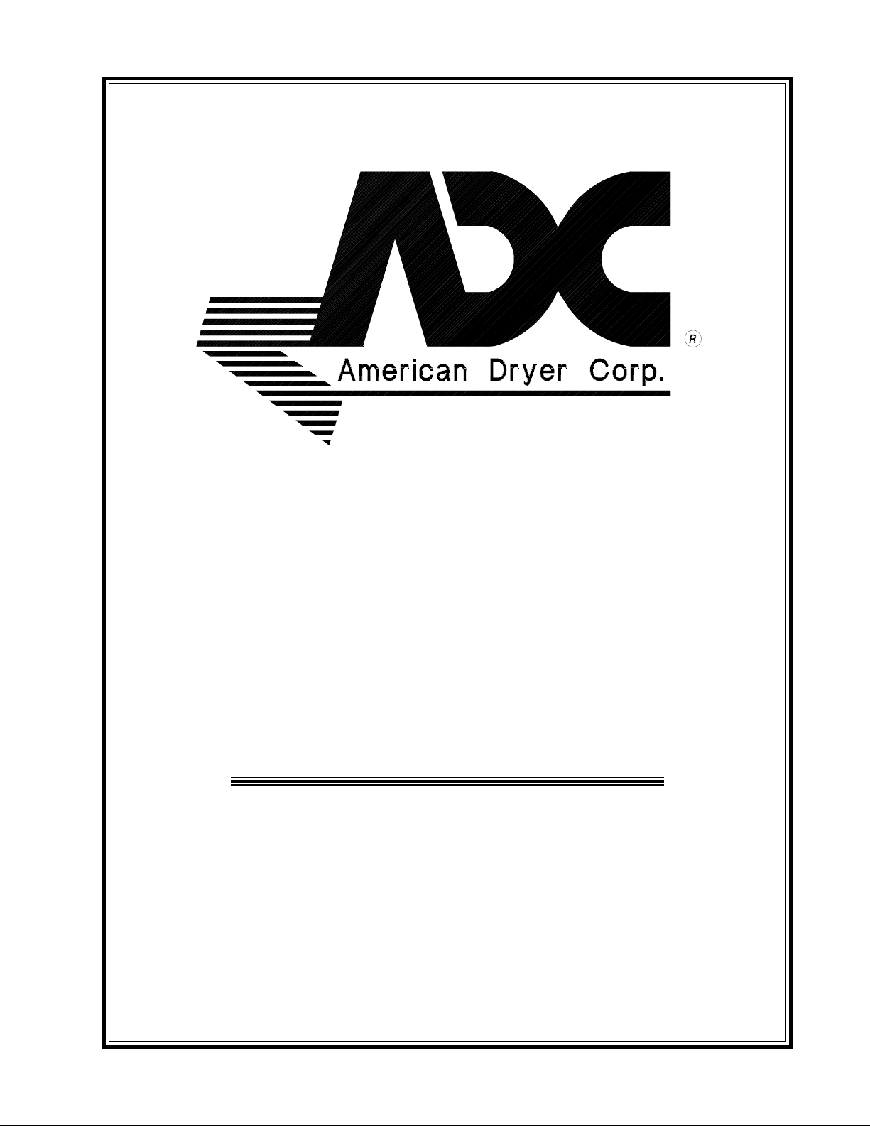
Phase 5 Coin Microprocessor Control Panel Assembly
3
Illus. No. Part No. Qty. Description
1 112526 1 Coin Keyboard Label Assembly
2 880959 1 Phase 5 Coin Microprocessor Control Panel Assembly
(includes illus. nos. 1, 2, 4, 5, 6, and 11)
880958 1 Coin Control Panel ONLY
3 150309 1 #10-16 x 1/2” Hex Head TEK Crimptite Screw
4 137213 1 Phase 5 Coin Controller
824998 1 Phase 5 Battery Clip
5 153010 2 #6 Star Washer
6 150005 2 #6-32 x 1/4” Phillips Round Head Machine Screw
7 881163 1 Microprocessor Coin Acceptor with Optical Switch
8 881143 1 Optical Switch
9 137023 1 Optical Switch Connector
10 137021 3 Microprocessor Socket
--- 880772 1 Single Coin Optic Switch Harness
--- 824080 1 Dual Coin Optic Switch Harness
--- 122800 1 Microprocessor (female) Pin Extraction Tool
11 136048 1 1/8-Amp (Slo-Blo) Fuse
IMPORTANT: Check label on computer chip to verify correct part number for microprocessor controller
(computer).
Telephone: (508) 678-9000 Fax: (508) 678-9447
Page 6
4
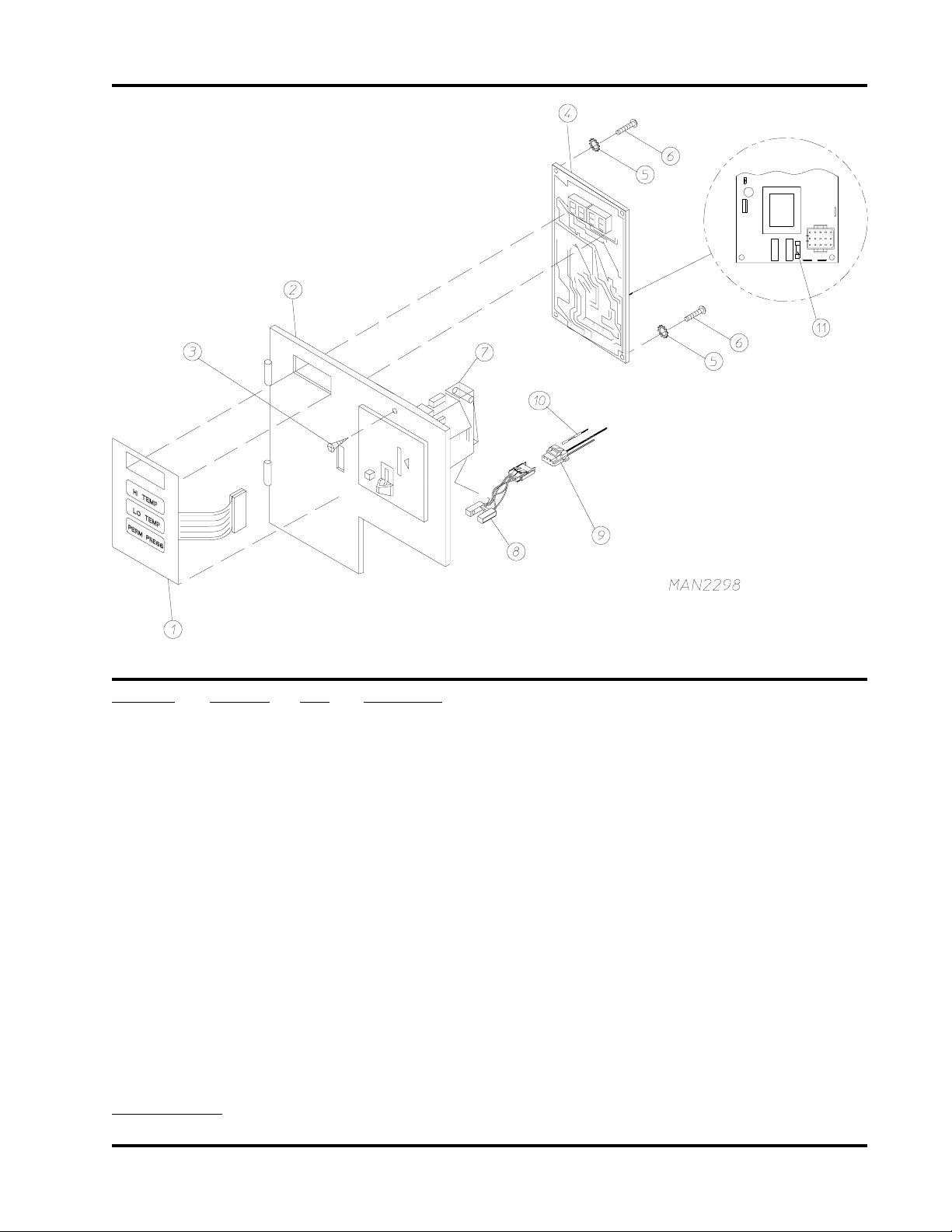
Phase 5 OPL Microprocessor Control Panel Assembly
Illus. No. Part No. Qty. Description
1 112535 1 OPL English Keyboard Label Assembly
112276 1 OPL Stick-On Labels (English Only) ... Not Illustrated
112275 1 OPL Stick-On Labels (Spanish, Italian, and Hebrew) ... Not Illustrated
112277 1 3-Language OPL Stick-On Labels
(English, Spanish, and Hebrew) ... Not Illustrated
112278 1 5-Language OPL Stick-On Labels
(Italian, Dutch, French, German, and Chinese) ... Not Illustrated
2 801225 1 Phase 5 Microprocessor Control Panel ONLY
824443 1 Phase 5 OPL Non-Reversing Microprocessor Control Panel Assembly
Complete
(includes illus. nos. 1 through 7)
3 137222 1 Phase 5 OPL Non-Reversing Controller
824998 1 Phase 5 Battery Clip
4 153010 2 #6 Star Washer
5 150005 2 #6-32 x 1/4” Phillips Round Head Machine Screw
6 150309 1 #10-16 x 1/2” Hex Head TEK Crimptite Screw
882541 1 Spring Turn Latch Assembly
7 136048 1 1/8-Amp (Slo-Blo) Fuse
IMPORTANT: Check label on computer chip to verify correct part number for microprocessor controller
(computer).
American Dryer Corporation 88 Currant Road / Fall River, MA 02720-4781
Page 7
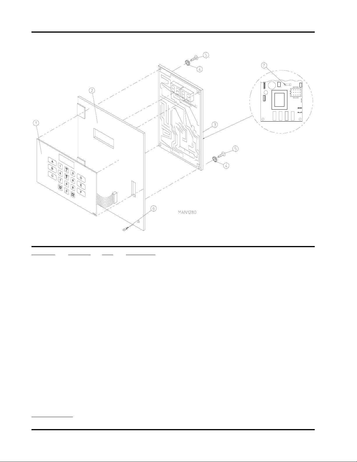
Phase 5 Microprocessor Control Box Assembly
For Coin and OPL Models
5
Illus. No. Part No. Qty. Description
1 141403 1 24 VAC Transformer
2 150301 2 #8-18 x 7/16” Phillips Pan Head TEK Screw
3 120715 1 30-Position Terminal Block
4 150002 2 #6-32 x 1” Round Head Machine Screw
5 151000 2 #6-32 Pal Nut
6 136057 * 1/2-Amp (Slo-Blo) Fuse ONLY
7 150301 * #8-18 x 7/16” Phillips Pan Head TEK Screw
8 136008 * Fuse Block/Strip
9 122641 1 15-Pin Microprocessor Connector
10 122706 * Socket Terminal
11 305542 1 Battery Bracket
12 150301 2 #8-18 x 7/16” Phillips Pan Head TEK Screw
* As required.
Telephone: (508) 678-9000 Fax: (508) 678-9447
Page 8
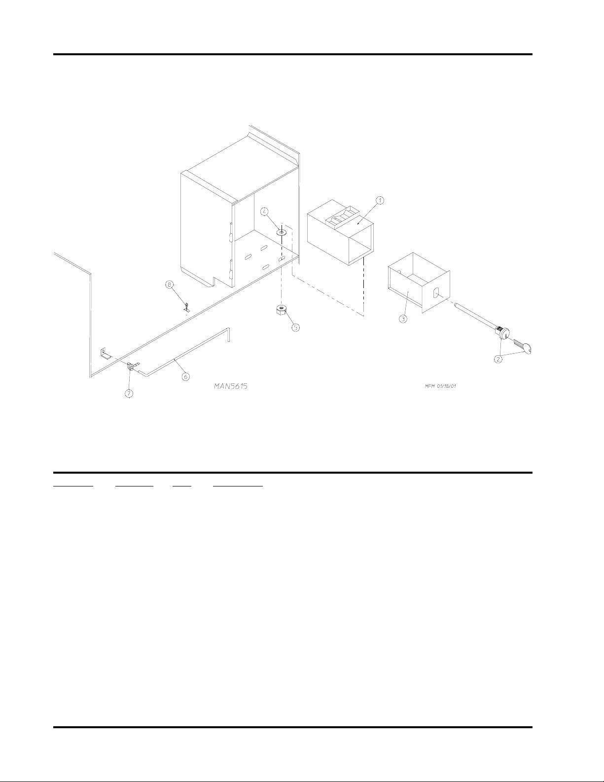
6
Microprocessor Coin Vault Assembly
Illus. No. Part No. Qty. Description
1 802146 1 Security Coin Vault Assembly Complete
(includes illus. nos. 1 through 3)
802139 1 High Security Coin Vault ONLY
2 160027 1 High Security Lock with Key (each keyed different)
160127* 1 Key ONLY For High Security Lock
160022 1 High Security Screw Lock with Key
160113* 1 Key ONLY For High Security Screw Lock
3 802138 1 High Security Coin Box Assembly with Lock
(includes illus. nos. 2 and 3)
802147 1 High Security Coin Box ONLY
4 153050 4 1/2” S.A.E. Flat Washer
5 152014 4 1/4-20 Free Spin Wash Nut
6 102502 1 Control Door Support Rod
7 102601 1 Control Door Rod Retainer Clip
8 102603 1 Control Door Support Rod Catch
* Specify key number when ordering.
American Dryer Corporation 88 Currant Road / Fall River, MA 02720-4781
Page 9
Main Door “Steel” Assembly
7
Illus. No. Part No. Qty. Description
1 881150 1 Black Main Door Assembly Complete
(includes illus. nos. 1, 2, and 8 through 15)
2 102354 1 Door Gasket
170730 1 Clear Glass Adhesive (10.3 oz. cartridge)
170731 1 Black Glass Adhesive (10.3 oz. cartridge)
3 881152 1 Black Top Hinge Block Assembly
(includes illus. nos. 3 and 4)
4 150445 2 1/4-20 x 3/4” Black Cap Head Setscrew
5 153031 1 1/4” Nylon Washer
6 881151 1 Black Bottom Hinge Block Assembly
(includes illus. nos. 5 through 7)
7 150445 2 1/4-20 x 3/4” Black Cap Head Setscrew
150443 2 1/4-20 x 3/4” Stainless Steel Cap Head Setscrew
8 150683 3 1/4-20 x 5/8” Black Carriage Bolt
9 152014 3 1/4-20 Free Spin Wash Nut
10 151010 1 #10-32 Black Hex Acorn Nut
11 150120 1 Door Latch Screw
12 150683 3 1/4-20 x 5/8” Black Carriage Bolt
13 152014 3 1/4-20 Free Spin Wash Nut
14 881210 1 Black Main Door Handle ONLY
170333 1 Stainless Steel Main Door Handle ONLY
15 102211 1 20-7/16” Door Glass
102360 1 Glass/Door Gasket Tape
(for models mfd. as of February 9, 2001)
170731 1 Black Glass Adhesive (10.3 oz. cartridge)
(for models mfd. prior to February 9, 2001)
Telephone: (508) 678-9000 Fax: (508) 678-9447
Page 10
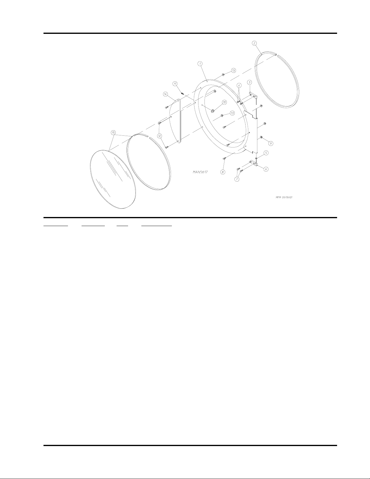
8
Slide Meter Case Assembly
American Dryer Corporation 88 Currant Road / Fall River, MA 02720-4781
Page 11

Slide Meter Case Assembly
Illus. No. Part No. Qty. Description
1 160099 1 Lock/Key/Cam and Hardware
160199* 1 Key ONLY for Slide Meter Lock
2 125908 1 Slide Meter Accumulator - 24 VAC - 60 RPM (60 Hz Only)
3 122643 9 Mate-N-Lock Pin ONLY
4 122642 1 9-Position Mini-Universal Socket
5 152014 4 1/4-20 Free Spin Wash Nut
6 122603 1 9-Position Connector (Mate-N-Lock)
7 122631 2 6-Position Connector (Mate-N-Lock)
8 881100 1 Slide Meter Modular J-Box Assembly
9 122701 21 Socket Terminal ONLY
10 125900 1 Slide Meter Case with Door Less Lock
11 154001 2 #10-24 Speed Nut
12 150300 4 #10-16 x 1/2” Hex Washer TEK Screw
13 881015 1 Slide Meter Control Panel (faceplate) Complete
(includes illus. nos. 11 and 13 through 16)
880937 1 Slide Meter Control Panel (faceplate) ONLY
14 122400 1 Rocker Heat Selector Switch
15 131917 1 Push-to-Start Relay - 24 VAC
16 123005 1 Red Light Indicator - 24 VAC
17 125903 1 Slide Meter Extension
18 -------- 1 Typical Slide Meter Coin Chute (not available from ADC)
19 -------- 1 Typical Slide Meter Coin Box (not available from ADC)
20 801701 1 Slide Meter Case Mounting Plate
21 102502 1 Control Door Support Rod
22 102601 1 Control Door Rod Retainer Clip
23 102603 1 Control Door Support Rod Catch
24 150207 2 #10-24 x 1/2” Round Head Machine Screw
9
* Specify key number when ordering.
Telephone: (508) 678-9000 Fax: (508) 678-9447
Page 12
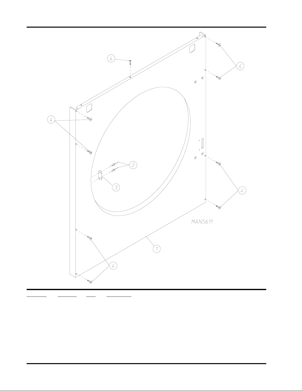
10
Cold Rolled Steel (CRS) Front Panel Assembly
Illus. No. Part No. Qty. Description
1 802511* 1 Front Panel Assembly (cold rolled steel [CRS] door)
2 154215 2 1/8” Pop Rivets
3 170330 1 Friction Door Latch
4 150309 9 #10-16 x 1/2” Hex Head TEK Crimptite Screw
150313 9 TORX Head Screw
(for models mfd. as of October 2, 2000)
150318 - Torx Plus Bit (for removal of Torx Screw)
* Specify color when ordering.
American Dryer Corporation 88 Currant Road / Fall River, MA 02720-4781
Page 13

Main Door Switch Assembly (Cold Rolled Steel [CRS] Type Door)
11
Illus. No. Part No. Qty. Description
1 150006 2 #6-32 x 7/8” Phillips Pan Head Machine Screw
2 152013 2 #6-32 Hex Nut
3 153010 2 #6 Star Washer
4 137005 1 Door Switch ONLY
5 122636 2 Flag Terminal
6 881211 1 Black Main Door Switch Housing ONLY
881212 1 Beige Main Door Switch Housing ONLY
881213 1 White Main Door Switch Housing ONLY
881214 1 Blue Main Door Switch Housing ONLY
881153 1 Black Main Door Switch Housing Complete
(includes illus. nos. 1 through 4 and 6)
881215 1 Beige Main Door Switch Housing Complete
(includes illus. nos. 1 through 4 and 6)
881216 1 White Main Door Switch Housing Complete
(includes illus. nos. 1 through 4 and 6)
881217 1 Blue Main Door Switch Housing Complete
(includes illus. nos. 1 through 4 and 6)
7 150301 2 #8-18 x 7/16” Phillips Pan Head TEK Screw
Telephone: (508) 678-9000 Fax: (508) 678-9447
Page 14

12
Basket (Tumbler)/Support Assemblies
Illus. No. Part No. Qty. Description
1 800843 1 Basket (tumbler) and Support Assembly Complete
(includes illus. nos. 1 through 10)
800717 1 Basket (tumbler) ONLY
2 154210 30 5/32” x 3/16” Pop Rivet
(for models mfd. as of December 12, 2000)
150309 30 #10-16 x 1/2” Hex Head TEK Crimptite Screw
(for models mfd. prior to December 12, 2000)
3 301318 2 Tapered Rib ONLY (low rib)
301317 1 Tapered Rib ONLY (high rib)
4 150518 1 5/16-18 x 3/8” Socket Screw
5 100916 3 3/8-16 x 25” Hex Head Tie Rod
6 153003 3 3/8” x 1-1/2” Fender Washer
7 800612 1 Basket (tumbler) Support ONLY
8 153001 3 5/16” Flat Washer
9 153002 3 5/16” Lock Washer
10 152004 3 5/16-18 Hex Nut
11 115986 1 Basket (tumbler) Felt Pad
American Dryer Corporation 88 Currant Road / Fall River, MA 02720-4781
Page 15

Lint Door Assembly
13
Illus. No. Part No. Qty. Description
1 882981* 1 Right Hand Hinge Lint Door Assembly with Slide Latch
2 170226 1 Slide Latch Flush Style (black)
3 117604 2 1/8” x 3/8” Neoprene Sponge Tape
* Specify color when ordering.
Telephone: (508) 678-9000 Fax: (508) 678-9447
Page 16

14
Sensor Bracket Assemblies
Microprocessor Sensor Bracket Assembly
Noncomputer Sensor Bracket Assembly
American Dryer Corporation 88 Currant Road / Fall River, MA 02720-4781
Page 17

Sensor Bracket Assemblies
Illus. No. Part No. Qty. Description
1 880251 1 1/4” Temperature Sensor Probe Assembly
(includes illus. nos. 1 and 5 through 8)
2 130103 1 225º Large Automatic Reset Thermostat
3 153010 2 #6 Star Washer
4 152000 2 #6-32 Hex Nut
5 121028 2 Insulated Terminal
6 122701 4 Socket Terminal
7 122605 1 4-Pin Socket Connector
8 154007 2 1/4” Tinnerman Push On Fastener
9 150005 2 #6-32 x 1/4” Phillips Round Head Machine Screw
10 801425 1 Microprocessor Sensor Bracket Assembly Complete
(includes illus. nos. 1 through 10)
11 122604 1 4-Pin Connector ONLY
12 122700 4 Pin Terminal ONLY
13 150301 2 #8-18 x 7/16” Phillips Pan Head TEK Screw
14 150005 * #6-32 x 1/4” Phillips Round Head Machine Screw
15 130103 1 225º Large Automatic Reset Thermostat
16 130111 1 150º Large Thermostat
17 130100 1 130º Large Thermostat
18 130101 1 180º Large Thermostat
19 153010 * #6 Star Washer
20 152000 * #6-32 Hex Nut
21 121028 ** Insulated Terminal
22 840065 1 Sensor Jumper (4)
23 122701 *** Socket Terminal
24 122605 1 4-Pin Socket Connector ONLY
840062 1 Sensor (4) Bracket Harness Assembly
(includes illus. nos. 21, 23, and 24)
25 801418 1 Noncomputer Sensor (4) Bracket Harness Assembly Complete
(includes thermostats)
(includes illus. nos. 14 through 27)
26 122604 1 4-Pin Connector ONLY
27 122700 *** Pin Terminal ONLY
122801 1 Pin/Socket Extraction Tool
28 150301 2 #8-18 x 7/16” Phillips Pan Head TEK Screw
15
* Qty. = 4 or 5.
** Qty. = 6 or 8.
*** Qty. = 3 or 4.
Telephone: (508) 678-9000 Fax: (508) 678-9447
Page 18

16
Control Door (25¢ Coin Models)
For Models Mfd. as of March 17, 2001
Illus. No. Part No. Qty. Description
1 883001** 1 Coin Control Door without Locks
(includes illus. nos. 1 through 4)
2 802514 1 Control Door Trim (cold rolled steel [CRS])
3 117604 3 1/8” x 3/8” Neoprene Sponge Tape
4 117605 2 1/4” x 3/8” Neoprene Sponge Tape
5 152014 5 1/4-20 Free Spin Wash Nut
6 160040 2 XX4451 Lock
7 160140 * XX4451 Key
8 881053 1 ADC Logo with Adhesive Tape
* As required.
** Specify color when ordering.
American Dryer Corporation 88 Currant Road / Fall River, MA 02720-4781
Page 19

Control Door (25¢ Coin Models)
For Models Mfd. between January 24, 2001 and March 16, 2001
17
Illus. No. Part No. Qty. Description
1 883001** 1 Coin Control Door without Locks
(includes illus. nos. 1 through 4)
2 802514 1 Control Door Trim (cold rolled steel [CRS])
3 117604 3 1/8” x 3/8” Neoprene Sponge Tape
4 117605 2 1/4” x 3/8” Neoprene Sponge Tape
5 152014 5 1/4-20 Free Spin Wash Nut
6 150420 2 #10-16 x 5/8” TEK Tamperproof Screw
7 160040 2 XX4451 Lock
8 160140 * XX4451 Key
9 881053 1 ADC Logo with Adhesive Tape
* As required.
** Specify color when ordering.
Telephone: (508) 678-9000 Fax: (508) 678-9447
Page 20

18
Control Door (Slide Meter Models)
For Models Mfd. as of March 17, 2001
Illus. No. Part No. Qty. Description
1 883000** 1 Slide Meter Control Door without Locks
(includes illus. nos. 1 through 4)
2 802514 1 Control Door Trim (cold rolled steel [CRS])
3 117604 3 1/8” x 3/8” Neoprene Sponge Tape
4 117605 2 1/4” x 3/8” Neoprene Sponge Tape
5 152014 5 1/4-20 Free Spin Wash Nut
6 160040 2 XX4451 Lock
7 160140 * XX4451 Key
8 881053 1 ADC Logo with Adhesive Tape
* As required.
** Specify color when ordering.
American Dryer Corporation 88 Currant Road / Fall River, MA 02720-4781
Page 21

Control Door (Slide Meter Models)
For Models Mfd. between January 24, 2001 and March 16, 2001
19
Illus. No. Part No. Qty. Description
1 883000** 1 Slide Meter Control Door without Locks
(includes illus. nos. 1 through 4)
2 802514 1 Control Door Trim (cold rolled steel [CRS])
3 117604 3 1/8” x 3/8” Neoprene Sponge Tape
4 117605 2 1/4” x 3/8” Neoprene Sponge Tape
5 152014 5 1/4-20 Free Spin Wash Nut
6 150420 2 #10-16 x 5/8” TEK - 3 Tamperproof Screw
7 160040 2 XX4451 Lock
8 160140 * XX4451 Key
9 881053 1 ADC Logo with Adhesive Tape
* As required.
** Specify color when ordering.
Telephone: (508) 678-9000 Fax: (508) 678-9447
Page 22

20
Control Door (OPL and Non 25¢ Coin Models)
For Models Mfd. as of March 17, 2001
Illus. No. Part No. Qty. Description
1 882999** 1 OPL and Non 25¢ Coin Control Door without Locks
(includes illus. nos. 1 through 4)
2 802514 1 Control Door Trim (cold rolled steel [CRS])
3 117604 3 1/8” x 3/8” Neoprene Sponge Tape
4 117605 2 1/4” x 3/8” Neoprene Sponge Tape
5 152014 5 1/4-20 Free Spin Wash Nut
6 160040 2 XX4451 Lock
7 160140 * XX4451 Key
8 881053 1 ADC Logo with Adhesive Tape
* As required.
** Specify color when ordering.
American Dryer Corporation 88 Currant Road / Fall River, MA 02720-4781
Page 23

Control Door (OPL and Non 25¢ Coin Models)
For Models Mfd. between January 24, 2001 and March 16, 2001
21
Illus. No. Part No. Qty. Description
1 882999** 1 OPL and Non 25¢ Coin Control Door without Locks
(includes illus. nos. 1 through 4)
2 802514 1 Control Door Trim (cold rolled steel [CRS])
3 117604 3 1/8” x 3/8” Neoprene Sponge Tape
4 117605 2 1/4” x 3/8” Neoprene Sponge Tape
5 152014 5 1/4-20 Free Spin Wash Nut
6 150420 2 #10-16 x 5/8” TEK Tamperproof Screw
7 160040 2 XX4451 Lock
8 160140 * XX4451 Key
9 881053 1 ADC Logo with Adhesive Tape
* As required.
** Specify color when ordering.
Telephone: (508) 678-9000 Fax: (508) 678-9447
Page 24

22
Control Door Assembly
For Models Mfd. prior to January 24, 2001
Illus. No. Part No. Qty. Description
1 882984* 1 Control Door with Cold Rolled Steel (CRS) Trim with Hinge
(includes illus. nos. 1 through 4)
2 802514 Cold Rolled Steel (CRS) Control Door Trim
3 117604 3 1/8” x 3/8” Neoprene Sponge Tape
4 117605 2 1/4” x 3/8” Neoprene Sponge Tape
5 152014 5 1/4-20 Free Spin Wash Nut
6 160040 2 XX4451 Lock
7 160140 2 XX4451 Key
8 881053 1 ADC Logo with Adhesive Tape
* Specify color when ordering.
American Dryer Corporation 88 Currant Road / Fall River, MA 02720-4781
Page 25

Basket (Tumbler) Bearing Assembly
For Models Mfd. as of April 27, 2001
23
Illus. No. Part No. Qty. Description
1 880209 1 1-3/8” 4 Bolt Pressed Steel Round Bearing
2 153005 12 3/8” Lock Washer
3 152005 4 3/8-16 Hex Nut
4 882544 1 Pillow Block Bearing Assembly Complete
(includes illus. nos. 4 through 14 and 18)
882542 1 Bearing Support ONLY
5 880202 1 1-3/8” Pillow Block Bearing
6 150601 2 3/8-16 x 2” Hex Bolt
7 153004 8 3/8” Flat Washer
8 153005 2 3/8” Lock Washer
9 152005 2 3/9-16 Hex Nut
10 154326 2 5/16-24 x 3/8” Setscrew Black
11 152004 4 5/16-18 Hex Nut
12 150621 2 5/16-18 x 1-1/2” Tap Bolt
13 153002 4 5/16” Lock Washer
14 150501 4 5/16-18 x 3/4” Tap Bolt
15 100713 1 1/4” x 1/4” x 7/8” Key
16 101100 1 18” Pulley
17 100100 1 5L-660 V-Belt (to idler assembly)
18 150610 2 5/16-18 x 1-1/2” Allen Setscrew
Telephone: (508) 678-9000 Fax: (508) 678-9447
Page 26

24
Basket (Tumbler) Bearing Assembly
For Models Mfd. prior to April 27, 2001
American Dryer Corporation 88 Currant Road / Fall River, MA 02720-4781
Page 27

Basket (Tumbler) Bearing Assembly
For Models Mfd. prior to April 27, 2001
Illus. No. Part No. Qty. Description
1 880203 1 1-3/8” Flange Bearing
2 153005 4 3/8” Lock Washer
3 152005 4 3/8-16 Hex Nut
4 882544 1 Pillow Block Bearing Assembly Complete
(includes illus. nos. 4 through 19)
882545 1 Pillow Block Bearing Assembly Complete (with rotational sensor)
(includes illus. nos. 4 through 16)
882542 1 Bearing Support ONLY
882543 1 Bearing Support ONLY (with rotational sensor)
5 880202 1 1-3/8” Pillow Block Bearing ONLY
880779 1 1-3/8” Pillow Block Bearing Assembly (with rotational sensor)
6 150601 2 3/8-16 x 2” Hex Bolt
7 153004 8 3/8” Flat Washer
8 153005 2 3/8” Lock Washer
9 152005 2 3/8-16 Hex Nut
10 154326 2 5/16-24 x 3/8” Black Setscrew
11 152004 4 5/16-18 Hex Nut
12 150621 2 5/16-18 x 1-1/2” Tap Bolt
13 153002 4 5/16” Lock Washer
14 150501 4 5/16-18 x 3/4” Tap Bolt
15 102120 1 Sintered 8 Magnet
16 824807 1 Rotational Sensor Assembly (with rotational sensor)
17 100713 1 1/4” x 1/4” x 7/8” Key
18 101100 1 18” Pulley
19 100111 1 5L-650 V-Belt (to idler assembly)
20 150610 2 5/16-18 x 1-1/2” Allen Setscrew
25
Telephone: (508) 678-9000 Fax: (508) 678-9447
Page 28

26
Lint Trap Assembly
Illus. No. Part No. Qty. Description
1 800429 1 Lint Trap Assembly Complete
(includes illus. nos. 1 and 3 through 5)
800419 1 Lint Trap ONLY
2 154200 7 5/32” Pop Rivet
3 304102 1 Lint Screen Holder
4 150300 3 #10-16 x 1/2” Hex Washer TEK Screw
5 800503 1 Lint Screen ONLY
6 323724 1 Lint Drawer Switch Bracket
7 122116 1 Lint Drawer Switch
8 150425 2 #12-24 x 3/8” Slotted Pan Head Screw
American Dryer Corporation 88 Currant Road / Fall River, MA 02720-4781
Page 29

Idler Bearing Assembly
27
Illus. No. Part No. Qty. Description
1 100111 1 5L-650 V-Belt
2 101129 1 9” x 2-1/2” Compound Pulley
3 100105 1 4L-520 V-Belt (idler to motor)
4 154301 2 5/16-18 x 1” Allen Setscrew
5 100705 1 3/16” x 3/16” x 1-3/8” Key
6 882576 1 Idler Bearing Assembly Complete
(includes illus. nos. 5 through 12)
7 150617 2 3/8-16 x 1” Hex Head Machine Bolt
8 153005 2 3/8” Lock Washer
9 153004 2 3/8” Flat Washer
10 801009 1 Idler Square Washer
11 152004 1 5/16-18 Hex Nut
12 150509 1 5/16-18 x 3” Hex Head Machine Bolt
Telephone: (508) 678-9000 Fax: (508) 678-9447
Page 30

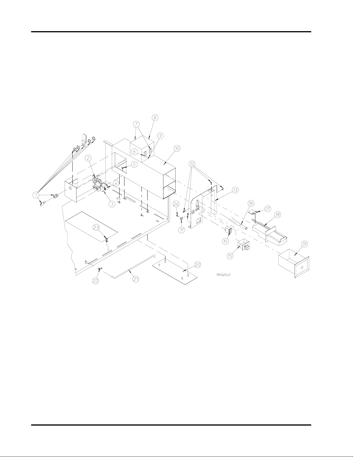
28
ELECTRIC OVEN (FRONT VIEW)
Electric Oven Assembly
ELECTRIC OVEN (REAR VIEW)
American Dryer Corporation 88 Currant Road / Fall River, MA 02720-4781
Page 31

Electric Oven Assembly
Illus. No. Part No. Qty. Description
1 803003* 1 Electric Oven Box ONLY
--------* 1 Electric Oven Assembly Complete
2 --------* 1 Electric Element
3 150300 2 #10-16 x 1/2” Hex Washer TEK Screw
4 802800 1 Sail Switch Box with Cover and Bracket ONLY
802801 1 Sail Switch Box Assembly Complete
(includes illus. nos. 4 through 12)
5 154004 1 Twin Speed Nut
6 150309 2 #10-16 x 1/2” Hex Head TEK Crimptite Screw
7 802799 1 Sail Switch Box Cover
8 122200 1 Sail Switch
9 150303 2 #4 x 3/4” Pan Head “A” Machine Screw
10 105500 1 Sail Switch Actuator Rod
11 319202 1 Sail Switch Damper (flat)
12 154002 1 1/8” Push On Fastener
13 150300 2 #10-16 x 1/2” Hex Washer TEK Screw
14 803100 1 Electric Oven Front Cover
15 320611 1 Large Relay Box Cover
16 150402 2 #10-24 x 5/8” Slotted Truss Head Machine Screw
17 130400 1 290º Hi-Limit
18 150300 2 #10-16 x 1/2” Hex Washer TEK Screw
19 154001 1 #10-24 Speed Nut
20 121010 1 L-70 Ground Lug
21 152014 3 1/4-20 Free Spin Wash Nut
22 --------* 1 Oven Relay
23 --------* 1 Oven Relay Replacement Coil
24 120081 - Internal Ceramic Insulator (2 per element)
25 120080 - External Ceramic Insulator (2 per element)
26 152008 - #10-32 Hex Nut (4 per element)
27 121011 - Bus Bar (sold by the foot)
28 --------* - Terminal Lug
29 153009 - #10 Star Washer (2 per element)
30 321300 1 Large Electric Oven Right Side Cover ONLY
31 150402 2 #10-24 x 5/8” Slotted Truss Head Machine Screw
29
* Refer to Electric Oven Component Application Chart on page 36.
Telephone: (508) 678-9000 Fax: (508) 678-9447
Page 32

30
Totally Enclosed, Fan-Cooled (T.E.F.C.) Motor Mount Assembly
Illus. No. Part No. Qty. Description
1 100105 1 4L-520 V-Belt (to idler bearing assembly)
2 101131 1 1/2” x 2-1/4” Motor Pulley (for use on 1Ø 60 Hz models Only)
3 150501 4 5/16-18 x 3/4” Tap Bolt
4 153002 4 5/16” Lock Washer
5 153001 4 5/16” Flat Washer
6 100065* 1 1/2 HP 115-230v 1Ø 60 Hz Totally Enclosed, Fan-Cooled (T.E.F.C.)
Motor with Plug
7 122701 8 Socket Terminal
8 137030 1 8-Pin Housing Connector ONLY
122801 1 Pin/Socket Extraction Tool
9 152004 4 5/16-18 Hex Nut
10 153002 4 5/16” Lock Washer
11 153001 4 5/16” Flat Washer
12 117600 4 Noise Suppressor Tape (sold by the foot)
13 154000 4 5/16-18 Tinnerman Nut
14 800909 1 1/2 HP Motor Mount ONLY (56Z frame)
803871* 1 1/2 HP 115-230v 1Ø 60 Hz Totally Enclosed, Fan-Cooled (T.E.F.C.)
Motor Mount Assembly with Plug Motor
(includes illus. nos. 3 through 8 and 13 through 19)
15 153050 2 1/2” S.A.E. Flat Washer
16 100604 1 12-1/2” Impellor (fan) with 1/2” Bore
17 100702 1 1/8” x 1/8” x 1-1/2” Key
18 153050 2 1/2” S.A.E. Flat Washer
19 152006 2 1/2-20 Left Hand Jam Nut
* Specify voltage when ordering.
American Dryer Corporation 88 Currant Road / Fall River, MA 02720-4781
Page 33

Gas Burner Assembly
31
Illus. No. Part No. Qty. Description
1 141104 2 Small Tube Burner
2 151001 2 #8-32 Pal Nut
3 150108 2 #8-32 x 1/2” Phillips Pan Head Machine Screw
4 140815 2 #37 Orifice (natural gas)
140800 2 #52 Orifice (liquid propane [L.P.] gas)
5 141230 1 1/2” Direct Spark Ignition (DSI) Manifold (2-port)
6 318714 1 1-Piece Gas Valve Bracket
7 150309 5 #10-16 x 1/2” Hex Head TEK Crimptite Screw
8 128927 1 Gas Valve
140411 1 Liquid Propane (L.P.) Conversion Kit For Gas Valve
9 809307 1 Ignitor-Probe Assembly
10 801048 1 ADC Direct Spark Ignition (DSI) Johnson Module (three [3] tries)
11 810030 1 Johnson Direct Spark Ignition (DSI) Module Mounting Bracket
12 150300 9 #10-16 x 1/2” Hex Washer TEK Screw
13 152013 2 #6-32 Hex Nut
14 142707 1 1/2” x 1-1/2” Long Black Nipple
15 142506 1 1/2” Street Elbow
16 142600 1 1/2” Black Union
17 142809 1 1/2” x 29-1/8” Pipe
18 882982 1 Direct Spark Ignition (DSI) Burner Box - Natural Gas
(includes illus. nos. 1 through 3 and 5 through 17)
882983 1 Direct Spark Ignition (DSI) Burner Box - Liquid Propane (L.P.) Gas
(includes illus. nos. 1 through 3 and 5 through 17)
Telephone: (508) 678-9000 Fax: (508) 678-9447
Page 34

32
Sail Switch/Hi-Limit Assemblies
Illus. No. Part No. Qty. Description
1 154004 1 Twin Speed Nut
2 150309 2 #10-16 x 1/2” Hex Head TEK Crimptite Screw
3 802799 1 Sail Switch Box Cover and Bracket
4 150303 2 #4 x 3/4” Pan Head “A” Machine Screw
5 122200 1 Sail Switch
6 105500 1 Sail Switch Actuator Rod
7 319202 1 Sail Switch Damper (flat)
8 154002 1 1/8” Push On Fastener
9 802801 1 Sail Switch Box Assembly Complete
(includes illus. nos. 1 through 9)
802800 1 Sail Switch Box with Cover and Bracket ONLY
10 142809 1 1/2” x 29-1/8” Pipe
11 150309 2 #10-16 x 1/2” Hex Head TEK Crimptite Screw
12 319704 1 Hi-Limit Mounting Bracket
13 151000 2 #6-32 Pal Nut
14 150001 2 #6-32 x 1/2” Round Head Machine Screw
15 130403 1 330º Hi-Limit
American Dryer Corporation 88 Currant Road / Fall River, MA 02720-4781
Page 35

Single-Phase (1Ø) Motor, Electric Relay Panel Assembly
33
Illus. No. Part No. Qty. Description
1 132475 1 2-Pole Contactor - 24 VAC
2 150299 2 #10 x 1” Hex Washer TEK Screw
3 824828 1 RC Network with Connector
- 322809 1 Back Electrical Box Cover ... Not Illustrated
- 150301 4 #8-18 x 7/16” Phillips Pan Head TEK Screw ... Not Illustrated
Telephone: (508) 678-9000 Fax: (508) 678-9447
Page 36

34
Slide Meter Control Box Assembly
Illus. No. Part No. Qty. Description
1 132475 1 2-Pole Contactor - 24 VAC
2 150299 2 #10 x 1” Hex Washer TEK Screw
3 150300 2 #10-16 x 1/2” Hex Washer TEK Screw
4 141403 1 24 VAC Transformer
5 136057 * 1/2-Amp (Slo-Blo) Fuse
6 150301 * #8-18 x 7/16” Phillips Pan Head TEK Screw
7 136008 * Fuse Block/Strip
8 150002 2 #6-32 x 1” Round Head Machine Screw
9 120715 1 30-Position Terminal Block
10 151000 2 #6-32 Pal Nut
11 152004 1 5/16-18 Hex Nut
12 153002 1 5/16” Lock Washer
13 305520 1 Rear Contact Plate
--- 322809 1 Back Electrical Box Cover ... Not Illustrated
--- 150301 4 #8-18 x 7/16” Phillips Pan Head TEK Screw ... Not Illustrated
* As required.
American Dryer Corporation 88 Currant Road / Fall River, MA 02720-4781
Page 37

Outer Top/Back Guard Assemblies
35
Illus. No. Part No. Qty. Description
1 322809 1 Back Electrical Box Cover
2 150301 4 #8-18 x 7/16” Phillips Pan Head TEK Screw
3 330660 1 Top Back Guard
4 150301 7 #8-18 x 7/16” Phillips Pan Head TEK Screw
5 150301 10 #8-18 x 7/16” Phillips Pan Head TEK Screw
6 330767 1 Outer Top
7 330609 1 Bottom Back Guard
8 150301 13 #8-18 x 7/16” Phillips Pan Head TEK Screw
9 103500 4 Leveling Leg
Telephone: (508) 678-9000 Fax: (508) 678-9447
Page 38

American Dryer Corporation 88 Currant Road / Fall River, MA 02720-4781
36
ADE-24 II
LEMENT
wKtloVesahPeriW*.yssAnevO
42084/064ø34ro315942864900021401#00333160101212JAEB253131
42614ø34ro35494286480002148#00133160101212JAEB253131
42042ø33 2394286490002136#00233132101211JAED163131
42802ø34ro35194286480002134#0033314 210121136APD963131
02083ø34ro383942864800021401#00033160101212JAEB253131
02042ø12 7294285490002124#00333122101212JAEF573131
02802ø12 5094285480002124#00333122101212JAEG583131
81084/064ø34ro305942863700021401#00033160101212JAEB253131
81614ø34ro344942863600021401#00033160101212JAEB253131
81042ø33 1394286370002138#0013314 0101212 34APD753131
81042ø12 5294286370002124#00333122101212 36APD963131
81802ø34ro34194286360002136#0023314 0101212JAED163131
81802ø12 3094286360002124#00333122101212JAEF573131
E
.ytQwK.oNtraPytQeziS.oNtraP.ytQ.oNtraP:N/P110121.oN.taC.oNtraP
O
VENWIRE
T
ERMINALLUG
BUSB
AR
O
VENRELAY
Electric Oven Component Application Chart
51083ø34ro373942863600021401#00033160101212JAEB253131
51042ø12 4294285370002126#0023313010121136APD963131
51802ø12 2094285360002124#0033312210121136APD963131
* Oven assemblies DO NOT include oven relay (contactor). This item must be ordered separately. When ordering Oven Assembly Complete,
specify 3 or 4 wire when applicable, as well as if dryer has Microprocessor or Non-Microprocessor controls.
N/A = Not available.
Page 39

Additional Parts Available
Part No. Description
112027 “Water Washed Fabrics” Label
112040 “Lint Compartment” Label
112041 “Caution - Exhausted” Label
112533 “Phase 5 Coin Program Location Summary” Label
112534 “Phase 5 OPL Program Location Summary” Label
120100 3/8” Straight (BX) Connector
120300 3/8” x 45° (BX) Connector
120400 3/8” Red Jacket (BX) Insulator
120600 3/8” Greenfield (BX)
120802 Red Butt Connector
120902 #74B Wire Nut
121014 1/4” Insulated (female) Terminal
121026 Tab Receptacle Combination
121499 5-1/2” Harness Tie
121500 8” Harness Tie
122804 Manometer (water column test gauge)
121497 33” Heavy Duty Cable Tie
121507 Snap Wire Tie Screw Mount
182457 3/4” Jiffy Clip (BX) Retainer Clip
404500 Almond Brush-In-Cap Bottle Touch-Up Paint
404502 White Brush-In-Cap Bottle Touch-Up Paint
404506 Almond “B” Brush-In-Cap Bottle Touch-Up Paint
404507 Cornflower Blue Brush-In-Cap Bottle Touch-Up Paint
880200 Electrical Terminal (assortment) Kit
37
Telephone: (508) 678-9000 Fax: (508) 678-9447
Page 40

ADC 450341 1-06/14/01-25 2 * 01/20/03-20
 Loading...