

Page 1
AD-145 Parts Manual
Phase 6 Microprocessor Models
1997/1998
American Dryer Corporation
88 Currant Road
Fall River MA 02720-4781
Telephone: (508) 678-9000 / Fax: (508) 678-9447
E-mail: techsupport@amdry.com
120196MM/abe
ADC Part No. 450167
Page 2
Retain This Manual In A Safe Place For Future Reference
American Dryer Corporation products embody advanced concepts in engineering, design, and safety. If this
product is properly maintained, it will provide many years of safe, efficient, and trouble-free operation.
ONLY properly licensed technicians should service this equipment.
OBSERVE ALL SAFETY PRECAUTIONS displayed on the equipment or specified in the installation/operator's
manual included with the dryer.
WARNING:
WARNING: The dryer must never be operated with any of the back guards, outer tops, or
We have tried to make this manual as complete as possible and hope you will find it useful. ADC reserves the
right to make changes from time to time, without notice or obligation, in prices, specifications, colors, and material,
and to change or discontinue models.
UNDER NO CIRCUMSTANCES should the door switch or the heat circuit devices
ever be disabled.
service panels removed. PERSONAL INJURY or FIRE COULD RESULT.
Important
For your convenience, log the following information:
DATE OF PURCHASE MODEL NO.
DISTRIBUT ORS NAME
Seria l Nu mber (s)
AD-145
Replacement parts can be obtained from your distributor or the ADC factory. When ordering replacement parts
from the factory, you can FAX your order to ADC at (508) 678-9447 or telephone your orders directly to the
ADC Parts Department at (508) 678-9000. Please specify the dryer model number and serial number in
addition to the description and part number, so that your order is processed accurately and promptly.
The illustrations on the following pages may not depict your particular dryer exactly. The illustrations are a
composite of the various dryer models. Be sure to check the descriptions of the parts thoroughly before ordering.
IMPORTANT NOTE TO PURCHASER
Information must be obtained from your local gas supplier on the instructions
to be followed if the user smells gas. These instructions must be posted in a
prominent location near the dryer.
Page 3

Table of Contents
Control Door Assembly .......................................................................................................................... 3
Microprocessor Control Panel Assembly ................................................................................................ 4
Microprocessor Control Box Assembly .................................................................................................. 5
Front Panel/Main Door Assemblies
for models mfd. as of October 24, 1997 ........................................................................................ 6
Front Panel/Main Door Assemblies
for models mfd. prior to October 24, 1997 ................................................................................... 7
Main Door Switch Assembly
for models mfd. as of October 24, 1997 .................................................................................... 8, 9
Main Door Switch Assembly
for models mfd. prior to October 24, 1997 .................................................................................. 10
Lint Door Assembly .............................................................................................................................. 11
Lint Drawer/Lint Drawer Switch Box Assemblies .................................................................................. 12
Microprocessor Temperature Sensor Bracket Assembly ........................................................................ 13
Tumbler Support Assemblies........................................................................................................... 14, 15
Tumbler Bearing Mount Assembly ................................................................................................... 16, 17
Idler Bearing Mount Assembly ........................................................................................................ 18, 19
Totally Enclosed, Fan-Cooled (T.E.F.C.) Motor Mount Assembly ................................................... 20, 21
Blower Motor Mount Assembly ............................................................................................................ 22
Fan Shaft Mount Assembly ................................................................................................................... 23
ADG-145 Hot Surface Ignition (HSI) Burner Assembly .................................................................. 24, 25
Microprocessor Reversing Contactor Mounting Panel Assembly ...................................................... 26, 27
Sail Switch Assembly ............................................................................................................................ 28
Page 4

Air Jet Assembly .................................................................................................................................. 29
Top Console Assembly ......................................................................................................................... 30
Pneumatic Valve Assembly .................................................................................................................... 31
Back Guard Assemblies ........................................................................................................................ 32
Step Down Transfaormer Application Listing ......................................................................................... 33
Additional Parts Available ..................................................................................................................... 34
Page 5
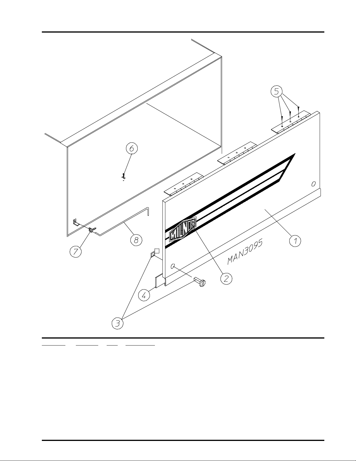
Control Door Assembly
3
Illus. No. Part No. Qty. Description
1* 881603 1 Control Door Assembly
(includes illus. nos. 1, 3, and 4 Only)
2 112368 1 Logo/Label ONLY
3 160005 2 Spring Turn Latch (2-piece)
4 117603 6 Gasket (sold by the foot)
5 150309 9 #10-16 x 1/2 Hex Head TEK Crimptite Screw
6 102600 1 Control Door Support Rod Catch
7 102601 1 Control Door Rod Retainer Clip
8 102505 1 Control Door Support Rod
* Specify color when ordering.
Telephone: (508) 678-9000 Fax: (508) 678-9447
Page 6
4
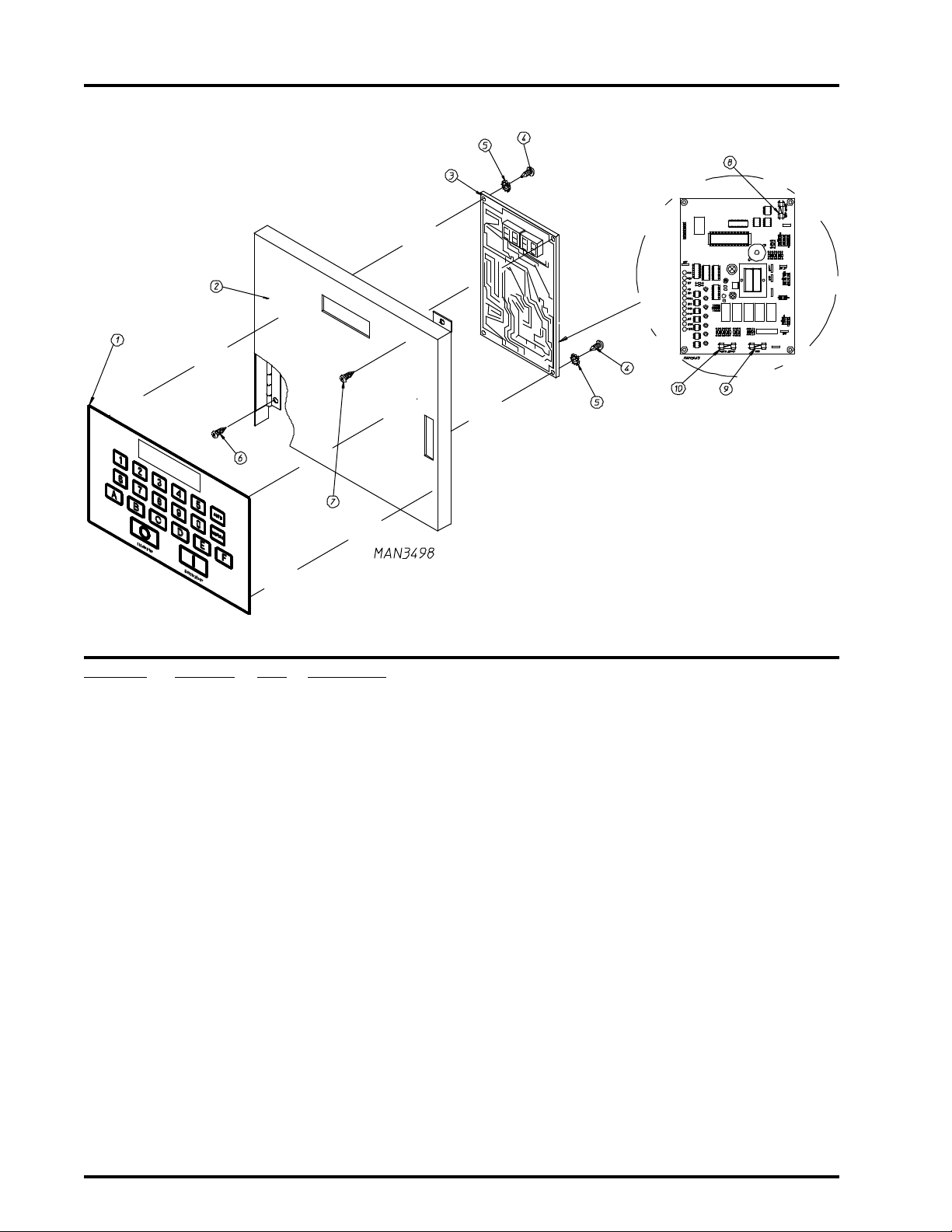
Microprocessor Control Panel Assembly
Illus. No. Part No. Qty. Description
1 112537 1 Phase 6 OPL Keypad
112276 1 OPL Stick-on Labels
(English Only) ... Not Illustrated
112275 1 OPL Stick-on Labels
(Spanish, Italian, and Hebrew) ... Not Illustrated
112277 1 3 Language OPL Stick-on Labels
(English, Spanish, and Hebrew) ... Not Illustrated
112278 1 5 Language OPL Stick-on Labels
(Italian, Dutch, French, German, and Chinese) ... Not Illustrated
2 881633 1 Computer Door ONLY
881635 1 Computer Door Complete
(includes illus. nos. 1 through 5 and 8 through 10)
881634 1 Computer Door with Battery Bracket
881643 1 Computer Door Complete with Battery Option
(includes illus. nos. 1 through 5 and 8 through 10)
3 137124 1 Phase 6 OPL Reversing Microprocessor Controller with Air Jet
4 150005 2 #6-32 x 1/4 Phillips Round Head Machine Screw
5 153010 2 #6 Star Washer
6 150000 3 #6-32 x 1/4 Slotted Round Head Machine Screw
7 150309 1 #10-16 x 1/2 Hex Head TEK Crimptite Screw
8 136048 1 1/8-Amp (Slo Blo) Fuse
9 136017 1 3.15-Amp (Fast Acting) Fuse
10 136019 1 1-Amp (Fast Acting) Fuse
American Dryer Corporation 88 Currant Road / Fall River, MA 02720-4781
Page 7
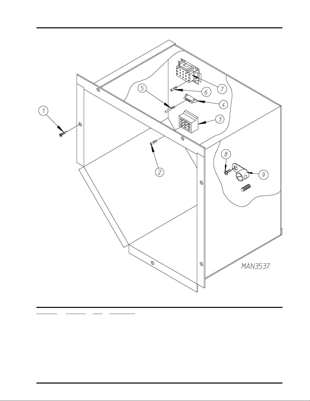
Microprocessor Control Box Assembly
5
Illus. No. Part No. Qty. Description
1 150301 6 #8-18 x 7/16 Phillips Pan Head TEK Screw
2 122701 8 M-N-L (Mate-N-Lok) Socket
3 122603 1 9-Pin Socket Connector
4 122621 1 4-Position M-N-L (Mate-N-Lok) Connector
5 122704 2 Split Pin ONLY
6 122705 15 Socket ONLY
7 122626 1 15-Pin Female Connector
8 150309 1 #10-16 x 1/2 Hex Head TEK Crimptite Screw
9 121010 1 L-70 Terminal Lug
Telephone: (508) 678-9000 Fax: (508) 678-9447
Page 8
6
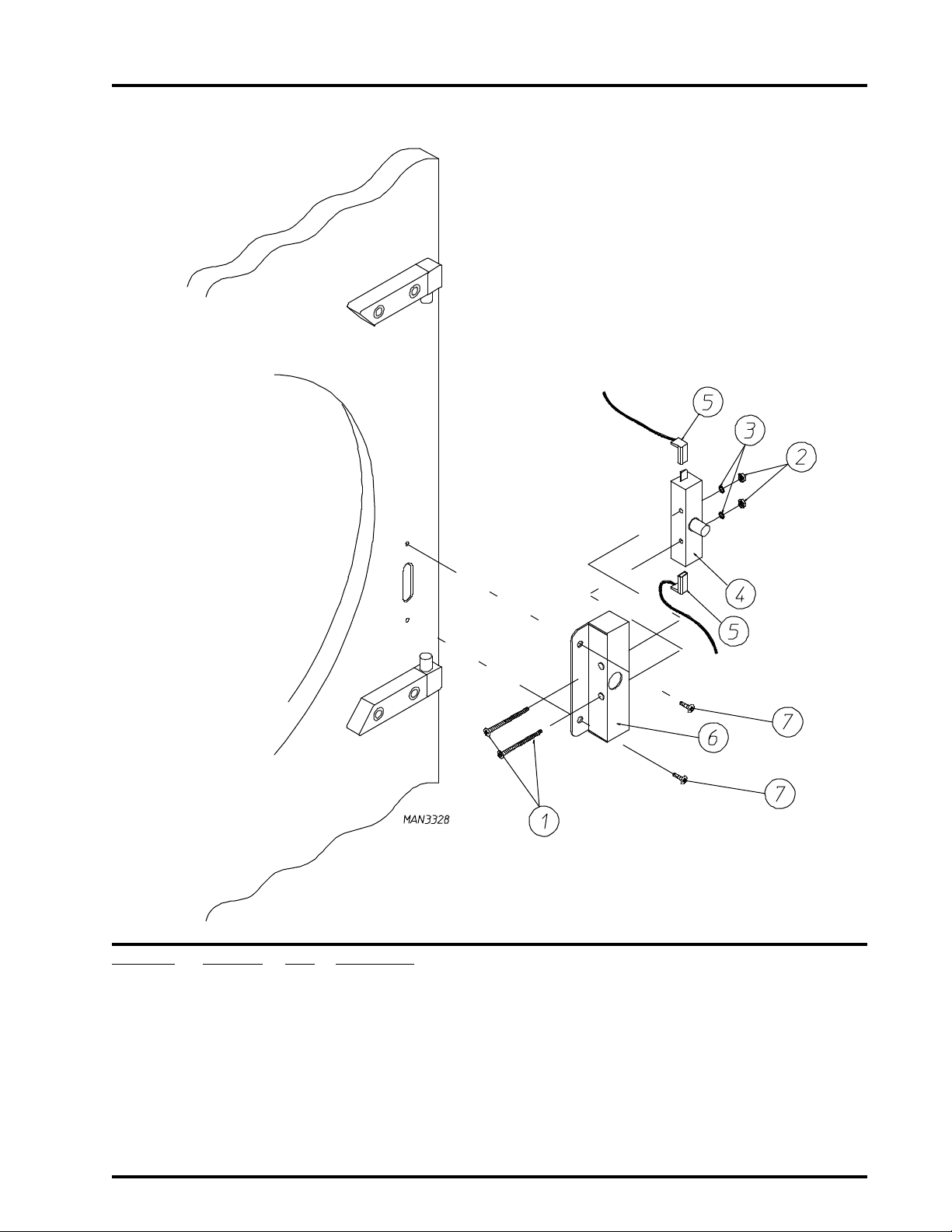
Main Door Switch
for models mfd. as of October 24, 1997
Illus. No. Part No. Qty. Description
1 150006 2 #6-32 x 7/8 Phillips Pan Head Machine Screw
2 152013 2 #6-32 Hex Nut
3 153010 2 #6 Star Washer
4 137005 1 Single Pole Door Switch
5 150443 4 1/4-20 x 3/4 Stainless Steel Cap Screw
6 881687 1 White Main Door Switch Housing ONLY
881695 1 Blue Main Door Switch Housing ONLY
881702 1 White Main Door Switch with Housing Assembly
(includes illus. nos. 1 through 4 and 6)
881700 1 Blue Main Door Switch with Housing Assembly
(includes illus. nos. 1 through 4 and 6)
7 150443 2 1/4-20 x 3/4 Stainless Steel Cap Screw
8 881441 1 White Bottom Hinge Block
881735 1 Blue Bottom Hinge Block
9 881440 1 White Top Hinge Block
881736 1 Blue Top Hinge Block
10 153031 1 Nylon Washer
American Dryer Corporation 88 Currant Road / Fall River, MA 02720-4781
Page 9
Main Door Switch Assembly
for models mfd. prior to October 24, 1997
7
Illus. No. Part No. Qty. Description
1 150006 2 #6-32 x 7/8 Phillips Pan Head Machine Screw
2 152013 2 #6-32 Hex Nut
3 153010 2 #6 Star Washer
4 137005 1 Door Switch
5 122636 2 Flag Terminal
6 881726 1 White Main Door Switch Housing
881698 1 White Main Door Switch Housing Complete
(includes illus. nos. 1 through 4 and 6)
7 150301 2 #8-18 x 7/16 Phillips Pan Head TEK Screw
Telephone: (508) 678-9000 Fax: (508) 678-9447
Page 10
8
Front Panel/Main Door Assemblies
for models mfd. as of October 24, 1997
American Dryer Corporation 88 Currant Road / Fall River, MA 02720-4781
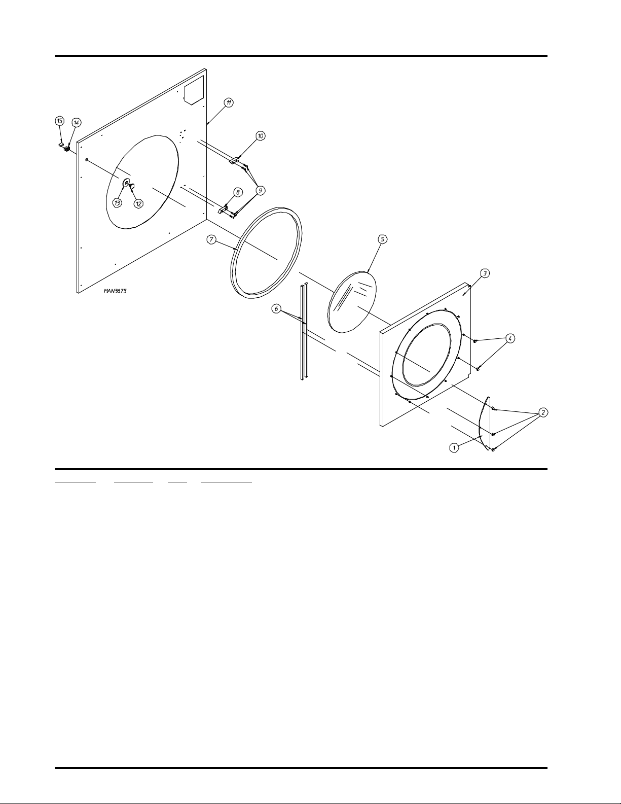
Page 11

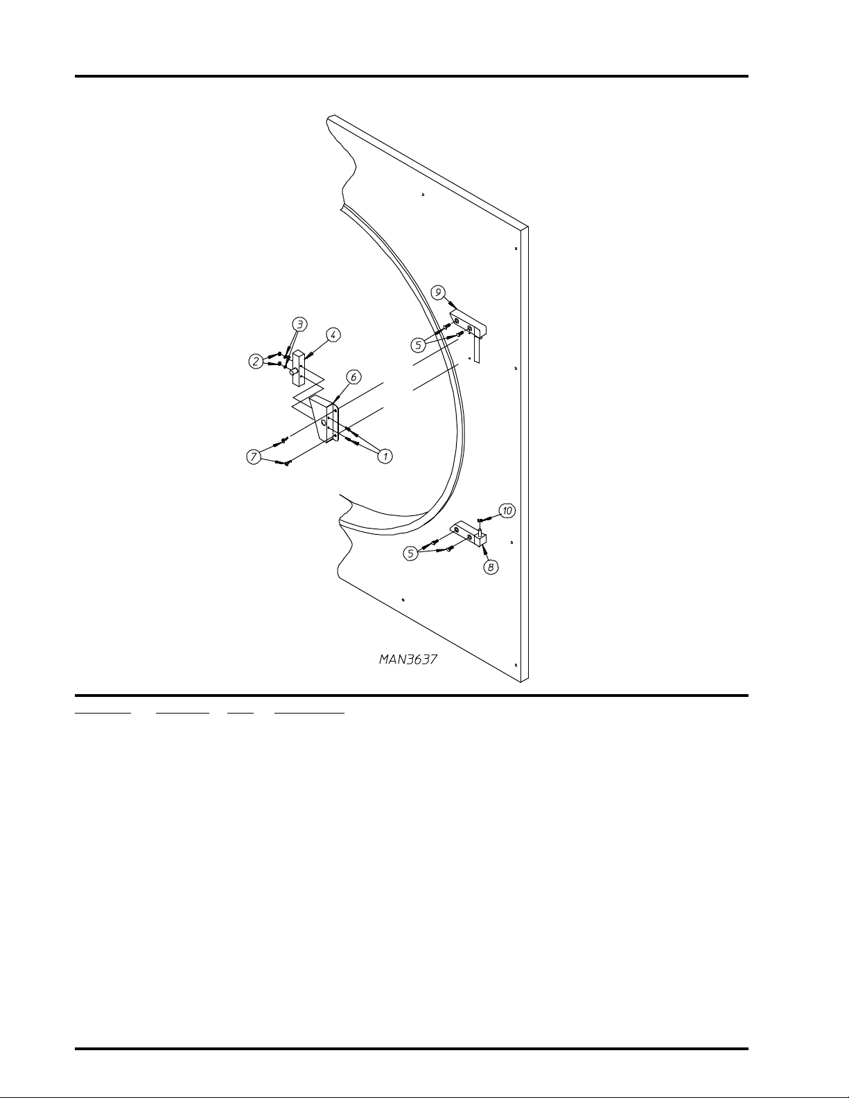
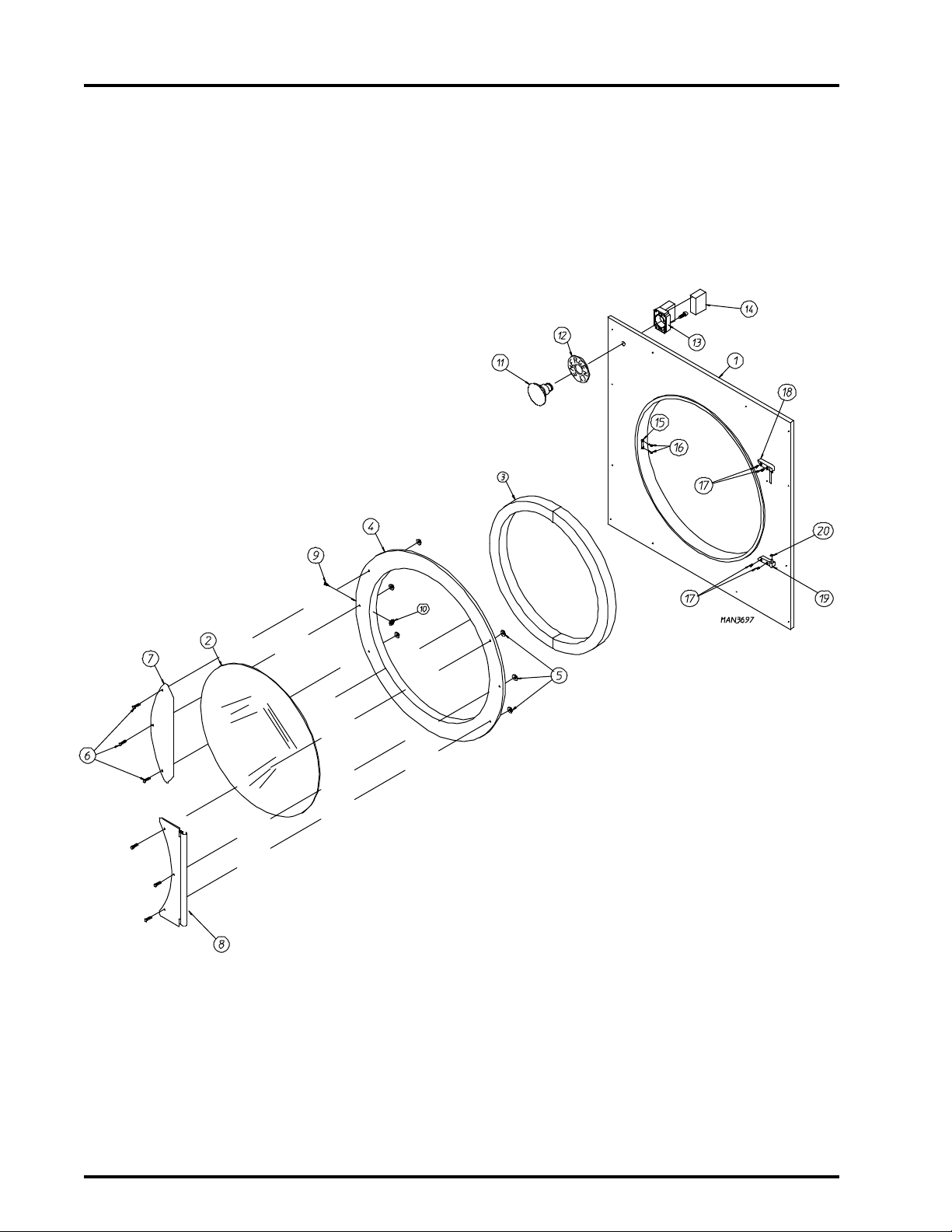
Front Panel/Main Door Assemblies
for models mfd. as of October 24, 1997
Illus. No. Part No. Qty. Description
1* 881690 1 Front Panel Assembly
(includes illus. nos. 1, 15, and 16)
2 102213 1 29-7/8 Door Glass
170730 1 Door Glass Adhesive (10.3 oz. cartridge)
3 102354 2 Main Door Gasket (7/8 x 7/8 x 73)
4 881761 1 Blue Main Door Assembly Complete
(includes illus. nos. 2 through 10)
881689 1 White Main Door Assembly Complete
(includes illus. nos. 2 through 10)
881684 1 White Main Door Ring
881756 1 Blue Main Door Ring
5 881806 6 1/4-20 Free Spin Wash Nut (White)
881807 6 1/4-20 Free Spin Wash Nut (Blue)
6 881740 6 1/4-20 x 5/8 (White) Carriage Bolt
881739 6 1/4-20 x 5/8 (Blue) Carriage Bolt
7 881688 1 White Main Door Handle
881737 1 Blue Main Door Handle
8 881685 1 White Main Door Hinge
881757 1 Blue Main Door Hinge
9 150120 1 Main Door Latch Screw
(#10-32 Dome Hex Head Screw)
10 151010 1 #10-32 Acorn Nut
11 122351 1 EMERGENCY STOP Push-Pull Button
12 122419 1 EMERGENCY STOP Nameplate
13 132387 1 Normally Closed (N.C.) Contact Block
14 132395 1 Normally Closed (N.C.) Contact Block with Base
15 170330 1 Friction Door Latch
16 154215 2 5/32 Pop Rivet
17 150443 4 1/4-20 x 3/4 Stainless Steel Cap Screw
18 881440 1 White Top Hinge Block
(includes illus. nos. 17 and 18)
881736 1 Blue Top Hinge Block
(includes illus. nos. 17 and 18)
19 881441 1 White Bottom Hinge Block
(includes illus. nos. 17 and 18)
881735 1 Blue Bottom Hinge Block
(includes illus. nos. 17 and 18)
20 153031 1 Nylon Washer
9
* Specify color when ordering.
Telephone: (508) 678-9000 Fax: (508) 678-9447
Page 12
10
Main Door/Front Panel Assemblies
for models mfd. prior to October 24, 1997
Illus. No. Part No. Qty. Description
1 881741 1 Flat Door Handle
2 151011 3 5/16-18 (Nickel Plated) Acorn Nut
3* 881552 1 Main Door Less Accessories
881816 1 Main Door Assembly Complete
(includes illus. nos. 1 through 7)
4 151011 9 5/16-18 Acorn Nut
5 102210 1 20-7/16 Door Glass
170730 1 Door Glass Adhesive (10.3 oz. cartridge)
6 102112 2 Door Magnet (5/16 x 1/4 x 34-3/4)
7 102356 1 Main Door Gasket (13-1/6 x 1-3/8 x 97-1/2)
8 881441 1 White Bottom Hinge Block
9 150445 4 1/4-20 x 3/4 Stainless Steel Black Head Cap Screw
10 881440 1 White Top Hinge Block
11* 881553 1 Front Panel Assembly
12 122351 1 EMERGENCY STOP Push-Pull Button
13 122419 1 EMERGENCY STOP Nameplate
14 132395 1 Normally Closed (N.C.) Contact Block with Base
15 132387 1 Normally Closed (N.C.) Contact Block
* Specify color when ordering.
American Dryer Corporation 88 Currant Road / Fall River, MA 02720-4781
Page 13

Lint Door Assembly
11
Illus. No. Part No. Qty. Description
1* 820945 1 Lint Door Assembly Complete
(includes illus. nos. 1, 2, and 4)
2 117602 5 Gasket (sold in feet)
3 150309 5 #10-16 x 1/2 Hex Head TEK Crimptite Screw
4 117600 9 Noise Suppressor Tape (sold by the foot)
* Specify color when ordering.
Telephone: (508) 678-9000 Fax: (508) 678-9447
Page 14

12
Lint Drawer/Lint Drawer Switch Box Assemblies
Illus. No. Part No. Qty. Description
1* 881554 1 Lint Drawer Assembly
2 821076 1 Lint Screen Assembly
3 150002 2 #6-32 x 1 Phillips Round Head Machine Screw
4 821116 1 Lint Drawer Switch Mounting Bracket
(includes illus. nos. 3 and 4)
821119 1 Lint Drawer Switch Mounting Bracket Assembly Complete
(includes illus. nos. 3 through 10)
5 136992 1 Lint Drawer Switch
6 153010 2 #6 Star Washer
7 152000 2 #6-32 Hex Nut
8 122605 2 4-Pin Socket Connector
9 122701 4 Socket Terminal
122801 1 Pin/Socket Extraction Tool
10 150309 2 #10-16 x 1/2 Hex Head TEK Crimptite Screw
* Specify color when ordering.
American Dryer Corporation 88 Currant Road / Fall River, MA 02720-4781
Page 15

Microprocessor Temperature Sensor Bracket Assembly
13
Illus. No. Part No. Qty. Description
1 820967 1 Microprocessor Temperature Sensor Bracket
820968 1 Microprocessor Temperature Sensor Bracket Complete
(includes illus. nos. 1 through 10)
2 150005 2 #6-32 x 1/4 Phillips Round Head Machine Screw
3 153010 2 #6 Star Washer
4 130112 1 225º Large Automatic Reset Thermostat
5 152000 2 #6-32 Hex Nut
6 121028 2 1/4 x .032 Insulated Terminal
7 122701 4 Socket Terminal
122801 1 Pin/Socket Extraction Tool
8 122605 1 4-Pin Socket Connector
9 154007 2 1/4 Push-on Fastener
10 880251 1 1/4 Temperature Sensor Probe Assembly
(includes illus. nos. 6 through 10)
11 150301 2 #8-18 x 7/16 Phillips Pan Head TEK Screw
Telephone: (508) 678-9000 Fax: (508) 678-9447
Page 16

14
Basket (Tumbler)/Support Assemblies
American Dryer Corporation 88 Currant Road / Fall River, MA 02720-4781
Page 17

Basket (Tumbler)/Support Assemblies
Illus. No. Part No. Qty. Description
1 881556* 1 Galvanized Basket (Tumbler) without Felt Collar
881558 1 Galvanized Basket (Tumbler) and Support Assembly Complete
(includes illus. nos. 1 through 13)
For models mfd. as of August 27, 1997
881642 1 Galvanized Basket (Tumbler) and Support Assembly Complete
(includes illus. nos. 1 through 13)
For models mfd. prior to August 27, 1997
2 150309 64 #10-16 x 1/2 Hex Head TEK Crimptite Screw
3 335028 4 Galvanized Basket (Tumbler) Rib
4 150500 1 5/16-18 x 3/4 Socket Button Head Screw
5 100911 12 1/2-13 x 37 Tie Rod
6 332139 4 Basket (Tumbler) Reinforcing Plate
7 332177 ** Basket (Tumbler) Shim
8 881555 1 Basket (Tumbler) Support
(for models mfd. as of August 27, 1997)
820909 1 Basket (Tumbler) Support
(for models mfd. prior to August 27, 1997)
9 152009 12 1/2-13 Hex Nut
10 153013 12 1/2 Lock Washer
11 153011 12 9/16 Flat Washer
12 100810 1*** 3-1/8 Retaining Ring
13 116007 1 Felt Collar
14 881619 1 Rotational Sensor Magnet Assembly
15
* Felt collar is not included and must be ordered separately.
** As required.
*** For models mfd. prior to August 27, 1997 a quantity of 2 was used.
Telephone: (508) 678-9000 Fax: (508) 678-9447
Page 18

16
Tumbler Bearing Mount Assembly
American Dryer Corporation 88 Currant Road / Fall River, MA 02720-4781
Page 19

Tumbler Bearing Mount Assembly
Illus. No. Part No. Qty. Description
1 100703 1 1/2 x 1/2 x 2 Key
2 101217 1 2-1/2 Bushing
(for models mfd. as of August 27, 1997)
101137 1 2-1/4 Bushing
(for models mfd. prior to August 27, 1997)
3* 100137 2 AB-91 V-Belt (to idler assembly)
4 101182 1 25 Tumbler Pulley
5 150602 4 5/8-11 x 3 Hex Head Bolt
6 153016 4 5/8 Flat Washer
7 100242 1 2-1/2 Pillow Block Bearing
(for models mfd. as of August 27, 1997)
880883 1 3-1/8 Pillow Block Bearing with Nylock Set Screws
(for models mfd. prior to August 27, 1997)
8 153016 4 5/8 Flat Washer
9 153015 2 5/8 Lock Washer
10 152010 2 5/8-11 Hex Nut
11 150600 2 3/8-16 x 1-1/2 Hex Head Bolt
12 152005 2 3/8-16 Hex Nut
13 821175 1 Tumbler Bearing Mount
(for models mfd. as of August 27, 1997)
820910 1 Tumbler Bearing Mount
(for models mfd. prior to August 27, 1997)
14 880883 1 3-1/8 Pillow Block Bearing with Nylock Set Screws
15 150604 2 1/2-20 x 3 Hex Head Bolt
16 152012 2 1/2-20 Hex Nut
17 152005 2 3/8-16 Hex Nut
18 153005 2 3/8 Lock Washer
19 153004 4 3/8 Flat Washer
20 150600 2 3/8-16 x 1-1/2 Hex Head Bolt
21 153004 2 3/8 Flat Washer
22 100801 2 5/8 Retaining Ring
23 332153 1 5/8 Hinge Pin
24 100810 1** 3-1/8 Retaining Ring
25 153018 2 1/4 Flat Washer
26 153007 2 1/4 Lock Washer
27 150512 2 1/4-20 x 1/2 Hex Head Bolt
28 824807 1 Rotational Sensor Assembly
29 880841 1 Rotational Sensor Mounting Bracket
17
* Replace in matched sets (both belts).
** For models mfd. prior to August 27, 1997 a quantity of 2 was used.
Telephone: (508) 678-9000 Fax: (508) 678-9447
Page 20

18
Idler Bearing Mount Assembly
American Dryer Corporation 88 Currant Road / Fall River, MA 02720-4781
Page 21

Idler Bearing Mount Assembly
Illus. No. Part No. Qty. Description
1 101152 1 SH x 1-3/8 Bushing
2 101143 1 2B x 3.8 Pulley
3* 100137 2 AB-91 V Belt (idler to basket [tumbler])
4 101184 1 SK x 1-3/8 Bushing
5* 100102 2 3V-740 V Belt (idler to motor)
6 101112 1 19 Idler Pulley
7 100730 1 5/16 x 5/16 x 4 Key
8 332152 1 Idler Shaft ONLY
9 880879 2 1-3/8 Pillow Block Bearing with Set Screws and Grease Fitting
10 153011 4 9/16 Flat Washer
11 150606 4 1/2-13 x 2 Hex Head Bolt
12 100802 2 1-3/8 Retaining Ring
13 332151 1 Idler Bearing Mount
820932 1 Idler Bearing Mount Assembly Complete
(includes illus. nos. 8 through 11 and 17 through 25)
14 150501 3 5/16-18 x 3/4 Hex Head Bolt
15 153001 3 5/16 Flat Washer
16 153011 4 9/16 Flat Washer
17 153026 4 1/2 Lock Washer
18 152011 4 1/2-13 Hex Nut
19 103005 1 Idler Adjustment Hinge
20 153002 6 5/16 Lock Washer
21 152004 6 5/16-18 Hex Nut
22 153005 4 3/8 Lock Washer
23 153004 4 3/8 Flat Washer
24 152005 4 3/8-16 Hex Nut
25 152005 2 3/8-16 Hex Nut
26 153005 2 3/8 Lock Washer
27 153005 2 3/8 Lock Washer
28 152034 2 3/8-16 x 3-1/2 Hex Head Bolt
29 150501 3 5/16 x 3/4 Hex Head Bolt
19
* Replace in matched sets (both belts).
Telephone: (508) 678-9000 Fax: (508) 678-9447
Page 22

20
Totally Enclosed, Fan-Cooled (T.E.F.C.) Motor Mount Assembly
American Dryer Corporation 88 Currant Road / Fall River, MA 02720-4781
Page 23

Totally Enclosed, Fan-Cooled (T.E.F.C.) Motor Mount Assembly
Illus. No. Part No. Qty. Description
1 101121 1 5/8 SK Bushing
2 101114 1 2.65 Pulley (for 60 Hz Models)
3* 100102 2 3V-740 V-Belt (motor to idler)
4 120200 1 3/8 x 90º Connector
5 150501 4 5/16 x 3/4 Hex Head Bolt
6 153001 4 5/16 Flat Washer
7 100050 1 1 HP 208/230/380/460v 3ø 50/60 Hz T.E.F.C. Motor (56Z frame)
8 800952 1 Tumbler Motor Mount (56Z frame)
820941** 1 50/60 Hz T.E.F.C. Tumbler Motor Mount Assembly Complete
(includes illus. nos. 1, 4 through 11, 15, and 16)
NOTE: MOTOR PULLEY
9 152004 4 5/16-18 Hex Nut
10 153002 4 5/16 Lock Washer
11 153001 4 5/16 Flat Washer
12 152004 4 5/16-18 Hex Nut
13 153002 4 5/16 Lock Washer
14 153001 4 5/16 Flat Washer
15 150619 4 3/8-16 x 3 Hex Head Machine Bolt
16 152005 2 3/8-16 Hex Nut
MUST BE ORDERED SEPARATELY.
21
* Replace in matched sets (both belts).
** Specify voltage when ordering.
IMPORTANT: For voltages higher than 460 volts, contact the factory for correct part number of motor and/or
motor mount assembly.
Telephone: (508) 678-9000 Fax: (508) 678-9447
Page 24

22
Blower Motor Mount Assembly
Illus. No. Part No. Qty. Description
1 100045* 1 5 HP 208/230/460v 3ø 60 Hz Blower (Fan/Impellor) Motor
100020 1 5 HP 380v 3ø 60 Hz (Fan/Impellor) Motor
2 101148 1 2B x 4.0 Pulley
3 101144 1 SH x 1-1/8 Bushing
4 100704 1 1/4 x 1/4 x 1-3/4 Key
5 152004 4 5/16-18 Hex Nut
6 153002 4 5/16 Lock Washer
7 153001 4 5/16 Flat Washer
8 835114 1 Motor Mount Adjustment Plate
9 153001 4 5/16 Flat Washer
10 153002 4 5/16 Lock Washer
11 150501 4 5/16-18 x 3/4 Hex Head Bolt
12 152004 4 5/16-18 Hex Nut
13 150503 2 5/16-18 x 2 Hex Head Bolt
14 332322 1 Motor Mount Adjustment Angle
15 153001 2 5/16 Flat Washer
16 153002 2 5/16 Lock Washer
17 150501 2 5/16-18 x 3/4 Hex Head Bolt
18** 100164 2 BX-51 V-Belt (motor to idler)
* Specify voltage when ordering.
** Replace in matched sets (both belts).
American Dryer Corporation 88 Currant Road / Fall River, MA 02720-4781
Page 25

Fan Shaft Mount Assembly
23
Illus. No. Part No. Qty. Description
1 100612 1 1-1/4 Bore x 15 Diameter Blower (Impellor/Fan) Wheel (Squirrel Cage)
2 821073 1 Fan Shaft Mount ONLY
835131 1 60 Hz Fan (Impellor/Blower) Shaft Mount Assembly Complete
(includes illus. nos. 1 through 18)
3 117600 4 Noise Suppressor Tape (sold by the foot)
4 152006 2 1/2-20 Left Hand Jam Nut
5 153050 1 1/2 Flat Washer
6 332280 1 Fan Shaft
7 881061 2 1-3/8 Flange Bearing with Set Screws and Grease Fitting
8 153004 4 3/8 Flat Washer
9 153005 4 3/8 Lock Washer
10 152005 4 3/18-16 Hex Nut
11 100812 2 1-3/8 Retaining Ring
12 880879 2 1-3/8 Pillow Block Bearing with Set Screws and Grease Fitting
13 153004 2 3/8 Flat Washer
14 153005 2 3/8 Lock Washer
15 150617 2 3/8-16 x 1 Hex Head Bolt
16 101185 1 2B x 6.2 Pulley (for 60 Hz Only)
17 100706 1 5/16 x 5/16 x 1-3/8 Key
18 101194 1 SDS x 1-3/8 Bushing
Telephone: (508) 678-9000 Fax: (508) 678-9447
Page 26

24
ADG-145 Hot Surface Ignition (HSI) Burner Assembly
American Dryer Corporation 88 Currant Road / Fall River, MA 02720-4781
Page 27

ADG-145 Hot Surface Ignition (HSI) Burner Assembly
Illus. No. Part No. Qty. Description
1 881570* 1 Natural Gas Burner Assembly Complete Less Orifices
(includes illus. nos. 1 through 17 and 19 through 39)
881571* 1 L.P. Gas Burner Assembly Complete Less Orifices
(includes illus. nos. 1 through 17 and 19 through 39)
881557 1 Burner Box ONLY
2 331291 1 Pipe Bracket
3 150309 2 #10-16 x 1/2 Hex Head TEK Crimptite Screw
4 142813 1 3/4 x 32-1/2 Nip ple
5 141300 1 3/4 Union Shut-off
6 142701 1 3/4 Closed Nipp le
7 142601 1 3/4 Union
8 142710 1 3/4 x 4 Nipple
9 142504 1 3/4 x 90º Elbow
10 142734 1 3/4 x 5-1/2 Nipple
11 150309 2 #10-16 x 1/2 Hex Head TEK Crimptite Screw
12 331089 1 Gas Valve Pipe Bracket
13 140026 1 3/4 24 VAC Redundant (natural gas) Gas Valve
(includes illus. nos. 13 and 14)
140411 - 24 VAC Gas Valve L.P. (liquid p ropane) Conversion Kit
881499** 1 ADG-145 L.P. (liquid propane) Conversion Kit
14 142902 1 3/4 to 1/2 Reducing Bushing (included with gas valve)
15 150309 2 #10-16 x 1/2 Hex Head TEK Crimptite Screw
16 331088 1 Gas Valve Pipe Bracket
17 141208 1 3-Port Manifold
18** 140839 3 # 2 Burne r Orifice (na tural gas) ON LY
140820 3 #29 Burner Orifice (liquid propane gas) ONLY
19 150309 4 #10-16 x 1/2 Hex Head TEK Crimptite Screw
20 335031 1 3-Port Manifold Support
21 150309 4 #10-16 x 1/2 Hex Head TEK Crimptite Screw
22 335037 1 Burner Box Front Cover Plate
23 150309 10 #10-16 x 1/2 Hex Head TEK Crimptite Screw
24 141110 3 Burner Tu be
25 331287 1 Burner Tube Support
26 150309 1 #10-16 x 1/2 Hex Head TEK Crimptite Screw
27 331290 1 Ignitor/Flame Probe Sight Hole
28 150309 5 #10-16 x 1/2 Hex Head TEK Crimptite Screw
29 --------- 1 Sail Switch (refer to Sail Switch Assembly on page 28)
30 390098 1 Burner Box C over Plate
31 881597 1 Hot Surface Ignitor
32 150309 2 #10-16 x 1/2 Hex Head TEK Crimptite Screw
33 821457 1 Hi- Limit Mounting Bracket
34 150001 2 #6-32 x 1 /2 Phillips Round Head Machine Screw
35 130401 1 330º Hi-Limit
36 151000 2 #6-32 Pal Nut
37 335037 1 Burner Box Back Cover Plate
38 150309 4 #10-16 x 1/2 Hex Head TEK Crimptite Screw
39 142753 1 1-1/4 x 3/4 R educing Coupling
40 128921 1 Fla me Probe
41 150301 2 #8- 18 x 7/16 Ph illips Pan Head TEK Screw
42 121400 3 7/8 Universal Bushin g
43 881797 1 HSI (Hot Surface Ignition) Module II
44 151001 2 #8-32 Pal Nut
25
* Orifices are not included and must be ordered separately.
** Consult factory for elevations over 2,000 feet.
Telephone: (508) 678-9000 Fax: (508) 678-9447
Page 28

26
Microprocessor Reversing Contactor Mounting Panel Assembly
American Dryer Corporation 88 Currant Road / Fall River, MA 02720-4781
Page 29

Microprocessor Reversing Contactor Mounting Panel Assembly
Illus. No. Part No. Qty. Description
27
1 132435 1 12-18 Amp Overload (for
132436 1 7-10 Amp Overload (for
2 132433 1 5 HP Contactor (for
3 151001 2 #8-32 Pal Nut
4 150008 2 #6-32 x 1-1/4 Round Head Machine Screw
5 120701 1 4-Position Terminal Block
6 132448 1 Reversing Contactor
7 --------- 1 Transformer
(refer to Step Down Transformer Application Listing on
881763 1 Transformer Termination Kit
8 137060 1 Arc Suppressor Board
9 137013 4 Nylon Stand Off
10 152004 2 5/16-18 Hex Nut
11 121012 1 Ground Lug
12 153002 2 5/16 Lock Washer
13* 136008 2 Fuse Holder
14* 136057 2 1/2-Amp (Slo Blo) Fuse
15 332346 1 Relay Panel
16 150301 3* or 5 #8-18 x 7/16 Phillips Pan Head TEK Screw
17 151000 2 #6-32 Pal Nut
18 120765 2 End Stop
19 150108 2 #8-32 x 1/2 Phillips Pan Head Machine Screw
20 150297 1 #10 x 1/2 Hex Washer TEK Screw
21 121010 1 L-70 Terminal Lug
22 120758 8 Din Mounting Rail (sold by the inch)
208/240 volt models ONLY
For
120758 9 Din Mounting Rail (sold by the inch)
For
460/480 volt models ONLY
23 135501 1 Double Pole Circuit Breaker (for
208/240 volt Only)
460/480 volt Only)
208/240 volt Only)
460/480 volt models Only)
page 33)
* For 208/240 volt models ONLY.
Telephone: (508) 678-9000 Fax: (508) 678-9447
Page 30

28
Sail Switch Assembly
Illus. No. Part No. Qty. Description
1 105500 1 Sail Switch Actuator Rod
2 319202 1 Sail Switch Damper (flat)
3 154002 1 1/8 Push-on Fastener
4 802800 1 Sail Switch Box with Cover and Bracket
(includes illus. nos. 4 and 8)
880793 1 Sail Switch Box Assembly Complete
(includes illus. nos. 1 through 4 and 6 through 10)
5 150300 2 #10 x 1/2 Hex Washer TEK Screw
6 150303 2 #4 x 3/4" Pan Head A Machine Screw
7 122200 1 Sail Switch ONLY
8 802799 1 Sail Switch Box Cover and Bracket
9 150309 2 #10-16 x 1/2 Hex Head TEK Crimptite Screw
10 154004 1 Twin Speed Nut
American Dryer Corporation 88 Currant Road / Fall River, MA 02720-4781
Page 31

Air Jet Assembly
29
Illus. No. Part No. Qty. Description
1 332700 1 Air Jet Tube
2 143287 1 1/4 x 1/8 M.P.T. Male Run Tee
3 143259 2 1/4 x 1/8 F.P.T. Bulkhead Fitting
4 143100 3 1/4 Aluminum Tube (sold by the foot)
5 332531 1 Air Jet Mounting Tube
6 152002 2 1/4-20 Hex Nut
7 153007 2 1/4 Lock Washer
8 143110 5 1/4 Poly Flow Tubing (sold by the foot)
9 143149 1 1/4 x 1/8 M.P.T. 90º Elbow
821081 1 Air Jet Assembly Complete
(includes illus. nos. 1 through 9)
Telephone: (508) 678-9000 Fax: (508) 678-9447
Page 32

30
Top Console Assembly
Illus. No. Part No. Qty. Description
1* 881568 1 Top Console ONLY (for Gas Models Only)
2 112284 1 Phase 6 OPL Program Location Summary Label
3 --------- 1 Dryer Data Label
(not for resale by ADC)
4 153007 12 1/4 Lock Washer
5 152005 12 1/4-20 Hex Nut
6 332323 1 32 Wire Channel
7 --------- 1 Pneumatic Valve
(refer to Pneumatic Valve Assembly on page 31)
8 121104 1 2 x 4 Junction Box
9 121105 1 Junction Box Cover
10 150510 4 1/4-20 x 3/4 Hex Head Machine Bolt
11 153018 4 1/4 Flat Washer
12* 332186 1 Control Door Channel
* Specify color when ordering.
American Dryer Corporation 88 Currant Road / Fall River, MA 02720-4781
Page 33

Pneumatic Valve Assembly
31
Illus. No. Part No. Qty. Description
1 143250 1 1/8 M.P.T. Brass Plug
(for models mfd. as of February 3, 1998)
100520 1 1/8 N.P.T. Silencer (muffler) ... Not Illustrated
(for models mfd. prior to February 3, 1998)
2 150002 1 #6-32 x 1 Phillips Round Head Machine Screw
3 100498 1 3-Way Micro Valve - 24 VAC
4 143268 1 1/8 Street Elbow
5 100472 1 1/4 x 1/8 Connector
6 330987 1 Micro Valve Support Bracket
7 153010 1 #6 Star Washer
8 152000 1 #6-32 Hex Nut
- 821105 1 Pneumatic Valve Assembly Complete
(includes illus. nos. 1 through 8)
Telephone: (508) 678-9000 Fax: (508) 678-9447
Page 34

32
Back Guard Assemblies
Illus. No. Part No. Qty. Description
1 332328 1 Bottom Back Guard
2 150301 28 #8-18 x 7/16 Phillips Pan Head TEK Screw
3 821096 1 Middle Back Guard
4 112014 1 High Voltage Label
5 112017 1 ADC Name, Address, Telephone Number Label
6 112230 1 Installation Instructions Label
8 821095 1 Top Back Guard
9 112284 1 Phase 6 OPL Program Location Summary Label
10 --------- 1 Dryer Data Label
(not for resale by ADC)
11* 332295 1 Blower Housing Front Access Panel
12* 332309 1 Side Access Panel
13 835123 1 Square Duct to Round Duct Transition Piece Assembly
-- 117505 ** Aluminum Duct Tape (sold by the foot)
* Specify color when ordering.
American Dryer Corporation 88 Currant Road / Fall River, MA 02720-4781
Page 35

Step Down Transformer Application Listing
NOTE: Each transformer requires one (1) Transformer Termination Kit (ADC Part No. 881763).
33
TEP
S
V
OLTAGE
208/240 3 132070 N/A*
380 3 or 4 N/A * N/A *
380 3 N/A* 132082
416 4 N/A* N/A*
416 3 N/A* N/A*
460/480 4 132067 N/A*
575 3 N/A* N/A*
D
OWN
RANSFORMER
T
W
IRE
S
ERVICE
SAGE
U
ADC P
G
AS
L
ART NO
ISTING
.
S
TE A M
* Not Available at time of printing. Contact factory for information nor listed.
Telephone: (508) 678-9000 Fax: (508) 678-9447
Page 36

34
Part No. Description
112098 Rotation Label
112280 Clean Lint Screen Label
114001 CAUTION - Exhaust/Lint Screen Label
114006 WARNING - Fire Hazards Label
120800 1/4 In-Line Connector
120802 Red Butt Connector
120902 #74B Wire Nut
120903 Crimp-On Wire Nut
120904 Red Wire Nut
121014 1/4 Insulated (female) Terminal
121499 4 Harness Tie
121500 7 Harness Tie
122804 Manometer/Hydro Gauge (for measuring gas pressure)
404502 White Brush-In-Cap Bottle Touch-Up Paint
404506 Beige Brush-In-Cap Bottle Touch-Up Paint
404507 Cornflower Blue-In-Cap Bottle Touch-Up Paint
Additional Parts Available
American Dryer Corporation 88 Currant Road / Fall River, MA 02720-4781
Page 37

35
ADC 450167 1 - 01/07/98-46 2* 05/21/98-50
Telephone: (508) 678-9000 Fax: (508) 678-9447
 Loading...