

Page 1
User Instructions
A.D.J. Supply Europe B.V.
Junostraat 2
6468 EW Kerkrade
The Netherlands
www.americandj.eu
Page 2
A.D.J. Supply Europe B.V. – www.americandj.eu – MOD QA60 Instruction Manual Page 2
©2018 ADJ Products, LLC all rights reserved. Information, specifications, diagrams, images, and instructions
herein are subject to change without notice. ADJ Products, LLC logo and identifying product names and
numbers herein are trademarks of ADJ Products, LLC. Copyright protection claimed includes all forms and
matters of copyrightable materials and information now allowed by statutory or judicial law or hereinafter
granted. Product names used in this document may be trademarks or registered trademarks of their respective
companies and are hereby acknowledged. All non-ADJ Products, LLC brands and product names are
trademarks or registered trademarks of their respective companies.
ADJ Products, LLC and all affiliated companies hereby disclaim any and all liabilities for property, equipment,
building, and electrical damages, injuries to any persons, and direct or indirect economic loss associated with
the use or reliance of any information contained within this document, and/or as a result of the improper,
unsafe, unsufficient and negligent assembly, installation, rigging, and operation of this product.
DOCUMENT VERSION
Please check www.adj.com for the latest revision/update of this guide.
Date
Document Version
Software
Version ≥
DMX Channel
Mode
Notes
01/19/18
1
1.00
4/5/6/9/10
Initial Release
Europe Energy Saving Notice
Energy Saving Matters (EuP 2009/125/EC)
Saving electric energy is a key to help protecting the enviroment. Please turn off all electrical products when they are not
in use. To avoid power consumption in idle mode, disconnect all electrical equipment from power when not in use. Thank
you!
Page 3

A.D.J. Supply Europe B.V. – www.americandj.eu – MOD QA60 Instruction Manual Page 3
Contents
INTRODUCTION ....................................................................................................................................................................... 4
FEATURES ................................................................................................................................................................................ 4
INSTALLATION ......................................................................................................................................................................... 4
SAFETY PRECAUTIONS ............................................................................................................................................................ 5
CONTROL PANEL LAYOUT ....................................................................................................................................................... 6
DMX SET UP ............................................................................................................................................................................ 7
DMX ADDRESSING .................................................................................................................................................................. 9
4 CHANNEL MODE ................................................................................................................................................................ 10
5 CHANNEL MODE ................................................................................................................................................................ 10
6 CHANNEL MODE ................................................................................................................................................................ 10
9 CHANNEL MODE ................................................................................................................................................................ 11
10 CHANNEL MODE .............................................................................................................................................................. 13
COLOR MACRO CHART .......................................................................................................................................................... 15
SYSTEM MENU ...................................................................................................................................................................... 17
OPERATING INSTRUCTIONS .................................................................................................................................................. 18
MASTER-SLAVE CONFIGURATION ......................................................................................................................................... 21
SNOOT EFFECT ...................................................................................................................................................................... 21
ADJ UC IR/ AIRSTREAM IR CONTROL .................................................................................................................................... 21
DIMMER CURVE CHART ........................................................................................................................................................ 22
DIMENSIONAL DRAWING ..................................................................................................................................................... 23
HOUSING CHANGE ................................................................................................................................................................ 24
FROST FILTER ........................................................................................................................................................................ 25
MULTIPLE UNIT POWER LINKING ......................................................................................................................................... 25
TROUBLE SHOOTING ............................................................................................................................................................. 25
CLEANING.............................................................................................................................................................................. 25
SPECIFICATIONS .................................................................................................................................................................... 26
ROHS - A great Contribution to the Conservation of Environment ..................................................................................... 27
WEEE – Waste of Electrical and Electronic Equipment ........................................................................................................ 27
NOTES ................................................................................................................................................................................... 28
Page 4

A.D.J. Supply Europe B.V. – www.americandj.eu – MOD QA60 Instruction Manual Page 4
INOZIONE
INTRODUCTION
Unpacking: Thank you for purchasing the MOD QA60 by ADJ Products, LLC. Every MOD QA60 has been
thoroughly tested and has been shipped in perfect operating condition. Carefully check the shipping carton for
damage that may have occurred during shipping. If the carton appears to be damaged, carefully inspect your
fixture for any damage and be sure all accessories necessary to operate the unit has arrived intact. In the case
damage has been found or parts are missing, please contact our toll free customer support number for further
instructions. Do not return this unit to your dealer without first contacting customer support.
Introduction: The ADJ MOD QA60 is a DMX intelligent, high powered LED par fixture. This fixture can be
used in a stand alone set up or connected in a Master/Slave set up. The MOD QA60 has seven operating
modes: Sound Active mode, Auto Run mode, Color Change mode, Color Fade mode, RGBA Dimmer mode,
Static Color mode, and DMX controlled. To optimize the performance of this product, please read these
operating instructions carefully to familiarize yourself with the basic operations of this unit. These instructions
contain important safety information regarding the use and maintenance of this unit. Please keep this manual
with the unit, for future reference.
Customer Support: If you encounter any problems, please contact your trusted American Audio shop. We
also offer the possibility, to contact us directly: You can contact us via our website www.americandj.eu or via
email: support@adj.eu
Warning! To prevent or reduce the risk of electrical shock or fire, do not expose this unit to rain or moisture.
Caution! There are no user serviceable parts inside this unit. Do not attempt any repairs yourself, doing so will
void your manufactures warranty. In the unlikely event your unit may require service please contact ADJ
Products, LLC.
PLEASE recycle the shipping carton when ever possible.
FEATURES
• Multi-Colors
• Seven Operating Modes
• Electronic Dimming 0-100%
• Built in Microphone
• DMX-512 protocol
• 3-Pin & 5-Pin DMX Connection
• Five DMX Modes: 4 Channel Mode, 5 Channel Mode, 6 Channel Mode, 9 Channel Mode, and 10 Channel
Mode.
• ADJ UC IR compatible and Airstream IR compatible
• Multiple Unit Power Linking (See page 25)
INCLUDED:
1 x Scissor Yoke
1 x powerCON Cable
3 x Frost Filters (20/40/60 Degrees)
OPTIONAL ACCESSORIES:
MOD Kit Pearl White Housing Case (Order Code: MOD510)
INSTALLATION
The unit should be mounted using a mounting clamp (not provided), affixing it to the mounting bracket that is
provided with the unit. Always ensure that the unit is firmly fixed to avoid vibration and slipping while operating.
Always ensure that the structure to which you are attaching the unit is secure and is able to support a weight
of 10 times the unit’s weight. Also, always use a safety cable that can hold 12 times the weight of the unit
when installing the fixture.
The equipment must be installed by a professional, and it must be installed in a place where it is out of the
reach of people’s grasp.
Page 5

A.D.J. Supply Europe B.V. – www.americandj.eu – MOD QA60 Instruction Manual Page 5
SAFETY PRECAUTIONS
• To reduce the risk of electrical shock or fire, do not expose this unit rain or moisture.
• Do not spill water or other liquids into or on to your unit.
• Do not attempt to operate this unit if the power cord has been frayed or broken. Do not attempt to remove or
break off the ground prong from the electrical cord. This prong is used to reduce the risk of electrical shock
and fire in case of an internal short.
• Disconnect from main power before making any type of connection.
• Do not remove the cover under any conditions. There are no user serviceable parts inside.
• Never operate this unit when it’s cover is removed.
• Never plug this unit in to a dimmer pack.
• Always be sure to mount this unit in an area that will allow proper ventilation. Allow about 6” (15cm) between
this device and a wall.
• Do not attempt to operate this unit, if it becomes damaged.
• This unit is intended for indoor use only, use of this product outdoors voids all warranties.
• During long periods of non-use, disconnect the unit’s main power.
• Always mount this unit in safe and stable matter.
• Power-supply cords should be routed so that they are not likely to be walked on or pinched by items placed
upon or against them, paying particular attention to the point they exit from the unit.
• Cleaning -The fixture should be cleaned only as recommended by the manufacturer. See page 25 for
cleaning details.
• Heat -The appliance should be situated away from heat sources such as radiators, heat registers, stoves, or
other appliances (including amplifiers) that produce heat.
• The fixture should be serviced by qualified service personnel when:
A. The power-supply cord or the plug has been damaged.
B. Objects have fallen, or liquid has been spilled into the fixture.
C. The fixture has been exposed to rain or water.
D. The fixture does not appear to operate normally or exhibits a marked change in performance.
E. The fixture has fallen and/or subjected to extreme handling.
Page 6

A.D.J. Supply Europe B.V. – www.americandj.eu – MOD QA60 Instruction Manual Page 6
CONTROL PANEL LAYOUT
LCD DISPLAY
UP BUTTON
DOWN BUTTON
DMX IN
DMX OUT
MODE BUTTON
SET UP BUTTON
POWER IN
POWER OUT
Page 7
A.D.J. Supply Europe B.V. – www.americandj.eu – MOD QA60 Instruction Manual Page 7
DMX SET UP
DMX-512: DMX is short for Digital Multiplex. This is a universal protocol used as a form of communication
between intelligent fixtures and controllers. A DMX controller sends DMX data instructions from the controller
to the fixture. DMX data is sent as serial data that travels from fixture to fixture via the DATA “IN” and DATA
“OUT” XLR terminals located on all DMX fixtures (most controllers only have a DATA “OUT” terminal).
DMX Linking: DMX is a language allowing all makes and models of different manufactures to be linked
together and operate from a single controller, as long as all fixtures and the controller are DMX compliant. To
ensure proper DMX data transmission, when using several DMX fixtures try to use the shortest cable path
possible. The order in which fixtures are connected in a DMX line does not influence the DMX addressing. For
example; a fixture assigned a DMX address of 1 may be placed anywhere in a DMX line, at the beginning, at
the end, or anywhere in the middle. When a fixture is assigned a DMX address of 1, the DMX controller knows
to send DATA assigned to address 1 to that unit, no matter where it is located in the DMX chain.
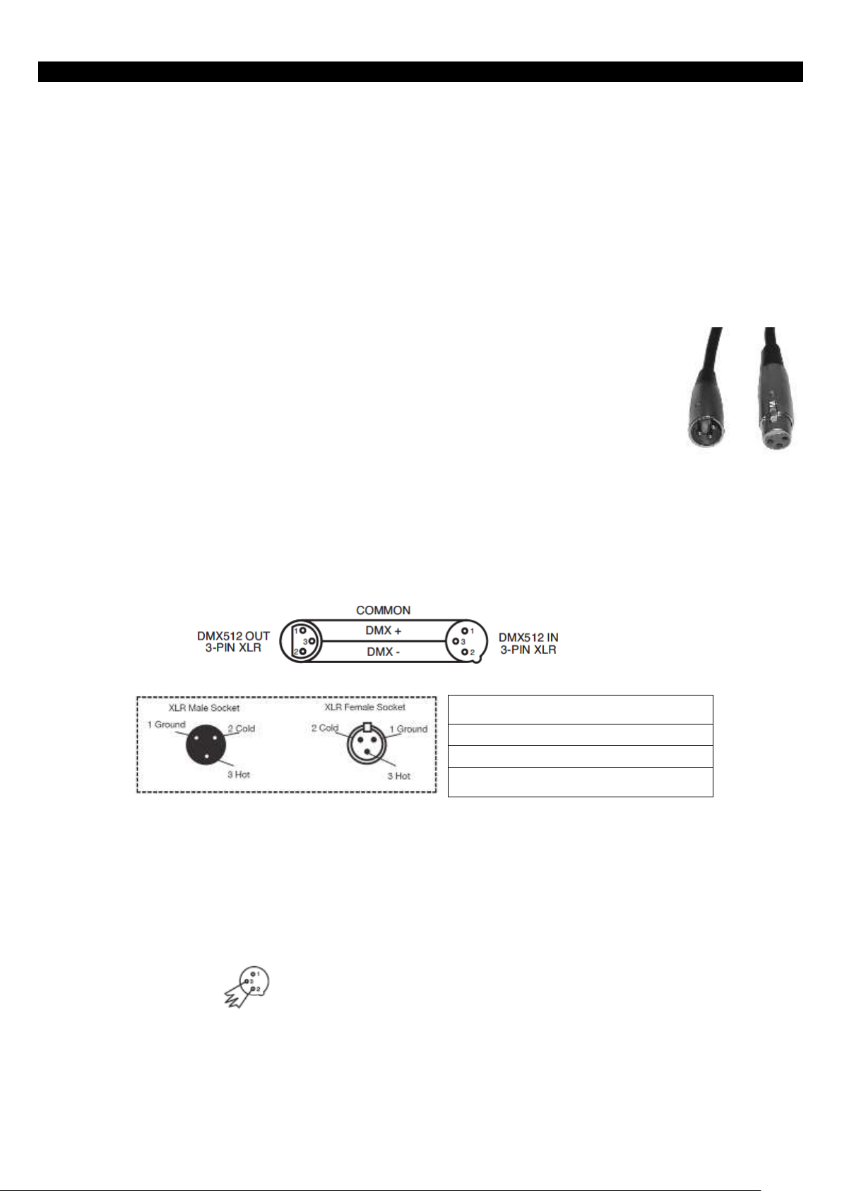
Data Cable (DMX Cable) Requirements (For DMX Operation): The MOD QA60 can be controlled via DMX512 protocol. The MOD QA60 has 5 DMX channel modes. The DMX address is set on the
rear panel of the MOD QA60. Your unit and your DMX controller require a standard 3-pin
XLR connector for data input and data output (Figure 1). We recommend Accu-Cable DMX
cables. If you are making your own cables, be sure to use standard 110-120 Ohm shielded
cable (This cable may be purchased at almost all pro lighting stores). Your cables should
be made with a male and female XLR connector on either end of the cable. Also
remember that DMX cable must be daisy chained and cannot be split.
Notice: Be sure to follow figures two and three when making your own cables. Do not use the ground lug on
the XLR connector. Do not connect the cable’s shield conductor to the ground lug or allow the shield conductor
to come in contact with the XLR’s outer casing. Grounding the shield could cause a short circuit and erratic
behavior.
Figure 2
XLR Pin Configuration
Pin1 = Ground
Pin2 = Data Compliment (negative)
Pin3 = Data True (positive)
Figure 3
Special Note: Line Termination. When longer runs of cable are used, you may need to use a terminator on
the last unit to avoid erratic behavior. A terminator is a 110-120 ohm 1/4 watt resistor which is connected
between pins 2 and 3 of a male XLR connector (DATA + and DATA -). This unit is inserted in the female XLR
connector of the last unit in your daisy chain to terminate the line. Using a cable terminator (ADJ part number
Z-DMX/T) will decrease the possibilities of erratic behavior.
Termination reduces signal errors and avoids
signal transmission problems and interference.
It is always advisable to connect a DMX
terminal, (Resistance120 Ohm 1/4 W) between
PIN 2 (DMX-) and PIN 3 (DMX +) of the last
fixture.
Figure 4
Figure 1
Page 8

A.D.J. Supply Europe B.V. – www.americandj.eu – MOD QA60 Instruction Manual Page 8
DMX SET UP (continued)
5-Pin XLR DMX Connectors. Some manufactures use 5-pin DMX-512 data cables for DATA transmission in
place of 3-pin. 5-pin DMX fixtures may be implemented in a 3-pin DMX line. When inserting standard 5-pin
data cables in to a 3-pin line a cable adaptor must be used, these adaptors are readily available at most
electric stores. The chart below details a proper cable conversion.
3-Pin XLR to 5-Pin XLR Conversion
Conductor
3-pin XLR Female (Out)
5-pin XLR Male (In)
Ground/Shield
Pin 1
Pin 1
Data compliment (- signal)
Pin 2
Pin 2
Data True (+ signal)
Pin 3
Pin 3
Not used
Do Not Use
Not used
Do Not Use
Page 9

A.D.J. Supply Europe B.V. – www.americandj.eu – MOD QA60 Instruction Manual Page 9
DMX ADDRESSING
DMX ADDRESSING
All fixtures should be given a DMX starting address when using a DMX controller, so the correct fixture
responds to the correct control signal. This digital starting address is the channel number from which the
fixture starts to “listen” to the digital control signal sent out from the DMX controller. The assignment of this
starting DMX address is achieved by setting the correct DMX address on the digital control display on the
fixture.
You can set the same starting address for all fixtures or a group of fixtures, or set different addresses for each
individual fixture. Setting all fixtures to the same DMX address will cause all fixtures to react in the same way,
in other words, changing the settings of one channel will affect all the fixtures
simultaneously.
If you set each fixture to a different DMX address, each unit will start to “listen” to the channel number you
have set, based on the quantity of DMX channels of each fixture. That means changing the settings of one
channel will only affect the selected fixture.
In the case of the MOD QA60, when in 10 Channel you should set the starting DMX address of the first unit to
1, the second unit to 11 (10 + 1), the third unit to 21 (11 + 10), and so on. (See chart below for more details.)
Channel Mode
Unit 1
Unit 2
Unit 3
Unit 4
Address
Address
Address
Address
4 channels
1 5 9
13
5 channels
1 6 11
16
6 channels
1 7 13
19
9 channels
1
10
19
28
10 channels
1
11
21
31
Page 10

A.D.J. Supply Europe B.V. – www.americandj.eu – MOD QA60 Instruction Manual Page 10
4 CHANNEL MODE
1 Channel
Value
Function
1
0 - 255
RED
0% - 100%
2
0 - 255
GREEN
0% - 100%
3
0 - 255
BLUE
0% - 100%
4
0 - 255
AMBER
0% - 100%
5 CHANNEL MODE
1 Channel
Value
Function
1
0 - 255
RED
0% - 100%
2
0 - 255
GREEN
0% - 100%
3
0 - 255
BLUE
0% - 100%
4
0 - 255
AMBER
0% - 100%
5
0 - 255
MASTER DIMMER
0% - 100%
6 CHANNEL MODE
1 Channel
Value
Function
1
0 - 255
RED
0% - 100%
2
0 - 255
GREEN
0% - 100%
3
0 - 255
BLUE
0% - 100%
4
0 - 255
AMBER
0% - 100%
5
0 - 31
32 - 63
64 - 95
96 - 127
128 - 159
160 - 191
192 - 223
224 - 255
STROBING
LED OFF
LED ON
STROBING SLOW - FAST
LED ON
PULSE STROBING SLOW - FAST
LED ON
RANDOM STROBING SLOW - FAST
LED ON
6
0 - 255
MASTER DIMMER
0% - 100%
Page 11

A.D.J. Supply Europe B.V. – www.americandj.eu – MOD QA60 Instruction Manual Page 11
9 CHANNEL MODE
1 Channel
Value
Function
1
0 - 255
RED
0% - 100%
2
0 - 255
GREEN
0% - 100%
3
0 - 255
BLUE
0% - 100%
4
0 - 255
AMBER
0% - 100%
5
0 - 31
32 - 63
64 - 95
96 - 127
128 - 159
160 - 191
192 - 223
224 - 255
STROBING
LED OFF
LED ON
STROBING SLOW - FAST
LED ON
PULSE STROBING SLOW - FAST
LED ON
RANDOM STROBING SLOW - FAST
LED ON
6
0 - 255
MASTER DIMMER
0% - 100%
7
0 - 51
52 - 102
103 - 153
154 - 204
205 - 255
PROGRAM SELECTION MODE
DIMMING MODE
COLOR MACRO MODE
COLOR CHANGE MODE
COLOR FADE MODE
SOUND ACTIVE MODE
8
0 - 255
0 - 15
16 - 31
32 - 47
48 - 63
64 - 79
80 - 95
96 - 111
112 - 127
128 - 143
144 - 159
160 - 175
176 - 191
192 - 207
208 - 223
224 - 239
240 - 255
COLOR MACROS/PROGRAMS
COLOR MACRO MODE
SEE THE COLOR MACRO CHART ON PAGES 15-16
COLOR CHANGE PROGRAMS
COLOR CHANGE 1
COLOR CHANGE 2
COLOR CHANGE 3
COLOR CHANGE 4
COLOR CHANGE 5
COLOR CHANGE 6
COLOR CHANGE 7
COLOR CHANGE 8
COLOR CHANGE 9
COLOR CHANGE 10
COLOR CHANGE 11
COLOR CHANGE 12
COLOR CHANGE 13
COLOR CHANGE 14
COLOR CHANGE 15
COLOR CHANGE 16
Page 12

A.D.J. Supply Europe B.V. – www.americandj.eu – MOD QA60 Instruction Manual Page 12
9 CHANNEL MODE (continued)
1 Channel
Value
Function
8
0 - 15
16 - 31
32 - 47
48 - 63
64 - 79
80 - 95
96 - 111
112 - 127
128 - 143
144 - 159
160 - 175
176 - 191
192 - 207
208 - 223
224 - 239
240 - 255
0 - 15
16 - 31
32 - 47
48 - 63
64 - 79
80 - 95
96 - 111
112 - 127
128 - 143
144 - 159
160 - 175
176 - 191
192 - 207
208 - 223
224 - 239
240 - 255
COLOR MACROS/PROGRAMS
COLOR FADE PROGRAMS
COLOR FADE 1
COLOR FADE 2
COLOR FADE 3
COLOR FADE 4
COLOR FADE 5
COLOR FADE 6
COLOR FADE 7
COLOR FADE 8
COLOR FADE 9
COLOR FADE 10
COLOR FADE 11
COLOR FADE 12
COLOR FADE 13
COLOR FADE 14
COLOR FADE 15
COLOR FADE 16
SOUND ACTIVE PROGRAMS
SOUND ACTIVE MODE 1
SOUND ACTIVE MODE 2
SOUND ACTIVE MODE 3
SOUND ACTIVE MODE 4
SOUND ACTIVE MODE 5
SOUND ACTIVE MODE 6
SOUND ACTIVE MODE 7
SOUND ACTIVE MODE 8
SOUND ACTIVE MODE 9
SOUND ACTIVE MODE 10
SOUND ACTIVE MODE 11
SOUND ACTIVE MODE 12
SOUND ACTIVE MODE 13
SOUND ACTIVE MODE 14
SOUND ACTIVE MODE 15
SOUND ACTIVE MODE 16
9
0 - 255
0 - 255
PROGRAM SPEED/SOUND SENSITIVITY
PROGRAM SPEED SLOW - FAST
SOUND SENSITIVITY LEAST - MOST SENSITIVE
When Channel 7 is between the values of 0-51, Channels 1-4 are used, and Channel 5 will control strobing.
When Channel 7 is between the values of 52-102, Channel 8 is in Color Macros Mode, and Channel 5 will control
strobing.
When Channel 7 is between the values of 103-153, Channel 8 is in Color Change Mode, and Channel 9 will control
the color change speed.
When Channel 7 is between the values of 154-204, Channel 8 is in Color Fade Mode, and Channel 9 will control
the color fade speed.
When Channel 7 is between the values of 205-255, Channel 8 is in Sound Active Mode, and Channel 9 will control
the sound sensitivity.
Page 13

A.D.J. Supply Europe B.V. – www.americandj.eu – MOD QA60 Instruction Manual Page 13
10 CHANNEL MODE
1 Channel
Value
Function
1
0 - 255
RED
0% - 100%
2
0 - 255
GREEN
0% - 100%
3
0 - 255
BLUE
0% - 100%
4
0 - 255
AMBER
0% - 100%
5
0 - 31
32 - 63
64 - 95
96 - 127
128 - 159
160 - 191
192 - 223
224 - 255
STROBING
LED OFF
LED ON
STROBING SLOW - FAST
LED ON
PULSE STROBING SLOW - FAST
LED ON
RANDOM STROBING SLOW - FAST
LED ON
6
0 - 255
MASTER DIMMER
0% - 100%
7
0 - 51
52 - 102
103 - 153
154 - 204
205 - 255
PROGRAM SELECTION MODE
DIMMING MODE
COLOR MACRO MODE
COLOR CHANGE MODE
COLOR FADE MODE
SOUND ACTIVE MODE
8
0 - 255
0 - 15
16 - 31
32 - 47
48 - 63
64 - 79
80 - 95
96 - 111
112 - 127
128 - 143
144 - 159
160 - 175
176 - 191
192 - 207
208 - 223
224 - 239
240 - 255
COLOR MACROS/PROGRAMS
COLOR MACRO MODE
SEE THE COLOR MACRO CHART ON PAGES 15-16
COLOR CHANGE PROGRAMS
COLOR CHANGE 1
COLOR CHANGE 2
COLOR CHANGE 3
COLOR CHANGE 4
COLOR CHANGE 5
COLOR CHANGE 6
COLOR CHANGE 7
COLOR CHANGE 8
COLOR CHANGE 9
COLOR CHANGE 10
COLOR CHANGE 11
COLOR CHANGE 12
COLOR CHANGE 13
COLOR CHANGE 14
COLOR CHANGE 15
COLOR CHANGE 16
Page 14

A.D.J. Supply Europe B.V. – www.americandj.eu – MOD QA60 Instruction Manual Page 14
10 CHANNEL MODE (continued)
1 Channel
Value
Function
8
0 - 15
16 - 31
32 - 47
48 - 63
64 - 79
80 - 95
96 - 111
112 - 127
128 - 143
144 - 159
160 - 175
176 - 191
192 - 207
208 - 223
224 - 239
240 - 255
0 - 15
16 - 31
32 - 47
48 - 63
64 - 79
80 - 95
96 - 111
112 - 127
128 - 143
144 - 159
160 - 175
176 - 191
192 - 207
208 - 223
224 - 239
240 - 255
COLOR MACROS/PROGRAMS
COLOR FADE PROGRAMS
COLOR FADE 1
COLOR FADE 2
COLOR FADE 3
COLOR FADE 4
COLOR FADE 5
COLOR FADE 6
COLOR FADE 7
COLOR FADE 8
COLOR FADE 9
COLOR FADE 10
COLOR FADE 11
COLOR FADE 12
COLOR FADE 13
COLOR FADE 14
COLOR FADE 15
COLOR FADE 16
SOUND ACTIVE PROGRAMS
SOUND ACTIVE MODE 1
SOUND ACTIVE MODE 2
SOUND ACTIVE MODE 3
SOUND ACTIVE MODE 4
SOUND ACTIVE MODE 5
SOUND ACTIVE MODE 6
SOUND ACTIVE MODE 7
SOUND ACTIVE MODE 8
SOUND ACTIVE MODE 9
SOUND ACTIVE MODE 10
SOUND ACTIVE MODE 11
SOUND ACTIVE MODE 12
SOUND ACTIVE MODE 13
SOUND ACTIVE MODE 14
SOUND ACTIVE MODE 15
SOUND ACTIVE MODE 16
9
0 - 255
0 - 255
PROGRAM SPEED/SOUND SENSITIVITY
PROGRAM SPEED SLOW - FAST
SOUND SENSITIVITY LEAST - MOST SENSITIVE
10
0 - 20
21 - 40
41 - 60
61 - 80
81 - 100
101 - 255
DIMMER CURVES
STANDARD
STAGE
TV
ARCHITECTURAL
THEATRE
DEFAULT TO UNIT SETTING
When Channel 7 is between the values of 0-51, Channels 1-4 are used, and Channel 5 will control strobing.
When Channel 7 is between the values of 52-102, Channel 8 is in Color Macros Mode, and Channel 5 will control
strobing.
When Channel 7 is between the values of 103-153, Channel 8 is in Color Change Mode, and Channel 9 will control
the color change speed.
When Channel 7 is between the values of 154-204, Channel 8 is in Color Fade Mode, and Channel 9 will control
the color fade speed.
When Channel 7 is between the values of 205-255, Channel 8 is in Sound Active Mode, and Channel 9 will control
the sound sensitivity.
Page 15

A.D.J. Supply Europe B.V. – www.americandj.eu – MOD QA60 Instruction Manual Page 15
COLOR MACRO CHART
Color No.
DMX
VALUE
RGBA COLOR INTENSITY
RED
GREEN
BLUE
AMBER
OFF 0 0 0 0
0
Color 1
1-4
80
255
234
80
Color2
5-8
80
255
164
80
Color3
9-12
77
255
112
77
Color4
13-16
117
255
83
83
Color5
17-20
160
255
77
77
Color6
21-24
223
255
83
83
Color7
25-28
255
243
77
77
Color8
29-32
255
200
74
74
Color9
33-36
255
166
77
77
Color10
37-40
255
125
74
74
Color11
41-44
255
97
77
74
Color12
45-48
255
71
77
71
Color13
49-52
255
83
134
83
Color14
53-56
255
93
182
93
Color15
57-60
255
96
236
96
Color16
61-64
238
93
255
93
Color17
65-68
196
87
255
87
Color18
69-72
150
90
255
90
Color19
73-76
100
77
255
77
Color20
77-80
77
100
255
77
Color21
81-84
67
148
255
67
Color22
85-88
77
195
255
77
Color23
89-92
77
234
255
77
Color24
93-96
158
255
144
144
Color25
97-100
255
251
153
153
Color26
101-104
255
175
147
147
Color27
105-108
255
138
186
138
Color28
109-112
255
147
251
147
Color29
113-116
151
138
255
138
Color30
117-120
99
0
255
100
Color31
121-124
138
169
255
138
Color32
125-128
255
255
255
255
Page 16

A.D.J. Supply Europe B.V. – www.americandj.eu – MOD QA60 Instruction Manual Page 16
COLOR MACRO CHART (continued)
Color No.
DMX
VALUE
RGBA COLOR INTENSITY
RED
GREEN
BLUE
AMBER
Color33
129-132
255
206
143
0
Color34
133-136
254
177
153
0
Color35
137-140
254
192
138
0
Color36
141-144
254
165
98
0
Color37
145-148
254
121 0 0
Color38
149-152
176
17 0 0
Color39
153-156
96 0 11
0
Color40
157-160
234
139
171
0
Color41
161-164
224 5 97
0
Color42
165-168
175
77
173
0
Color43
169-172
119
130
199
0
Color44
173-176
147
164
212
0
Color45
177-180
88 2 163
0
Color46
181-184
0
38
86
0
Color47
185-188
0
142
208
0
Color48
189-192
52
148
209
0
Color49
193-196
1
134
201
0
Color50
197-200
0
145
212
0
Color51
201-204
0
121
192
0
Color52
205-208
0
129
184
0
Color53
209-212
0
83
115
0
Color54
213-216
0
97
166
0
Color55
217-220
1
100
167
0
Color56
221-224
0
40
86
0
Color57
225-228
209
219
182
0
Color58
229-232
42
165
85
0
Color59
233-236
0
46
35
0
Color60
237-240
8
107
222
0
Color61
241-244
255 0 0
0
Color62
245-248
0
255 0 0
Color63
249-252
0 0 255
0
Color64
253-255
0 0 0
255
Page 17

A.D.J. Supply Europe B.V. – www.americandj.eu – MOD QA60 Instruction Manual Page 17
SYSTEM MENU
MENU
DESCRIPTION
DMX MODE
ADDR:001~512
Set the DMX starting address
DMX MODE
CHAN:4/5/6/9/10
Set the unit DMX channels
DMX MODE NO:BLACK
When DMX signal is lost or interrupted, the unit will default to BLACKOUT option. It will
switch all LED’s off
DMX MODE NO:HOLD
When DMX signal is lost or interrupted, the unit will default to HOLD option. It will hold the
last state before signal was lost.
DMX MODE NO:AUTO
When DMX signal is lost or interrupted, the unit will default to AUTO option. It will run the
internal programs.
DMX MODE
NO:MANUA
When DMX signal is lost or interrupted, the unit will default to the manual color setting
DMX MODE
DELAY:0~4
Select the unit delay mode
SLAVE MODE
Set the unit into slave mode
SOUND PRO:01~16
Select the 16 sound active modes
SOUND SENS:00~08
Adjust the sound active sensitivity level,00 is sound active off,01 is the lowest level,8 is
highest level.
MANUAL RED:000~255
Adjust the intensity of the red color
MANUAL
GREN:000~255
Adjust the intensity of the green color
MANUAL
BLUE:000~255
Adjust the intensity of the blue color
MANUAL
AMBE:000~255
Adjust the intensity of the amber color
MANUAL
STROB:00~15
Adjust the flash speed,00 is flash off,01 is slowest,15 is fastest
JUMP RUN
SNAP:01~16
Select the 16 color change modes
JUMP RUN
SPEED:01~16
Adjust the speed of the color change mode
FADE RUN
SNAP:01~16
Select the 16 color dreaming modes
FADE RUN
SPEED:01~16
Adjust the speed of the color dreaming mode
AUTO RUN FAD+SNAP
Select the auto run mode
AUTO RUN
SPEED:01~16
Adjust the speed of the auto run mode
CLR MACS
COLOR:00~64
Select the 64 static colors
CLR MACS
STROB:00~15
Adjust the strobe speed,00 is strobe off,01 is slowest,15 is fastest
OPTION BLGT:ON
LCD backlight always on
OPTION BLGT:OFF
LCD backlight will be off after 20 seconds
OPTION IR:ON
IR remote function on
OPTION IR:OFF
IR remote function off
OPTION SYSRESET
Initialize the unit at the extra factory setting
Page 18

A.D.J. Supply Europe B.V. – www.americandj.eu – MOD QA60 Instruction Manual Page 18
OPERATING INSTRUCTIONS
The control panel will lock up after 5 seconds of inactivity. Press the MODE button for at least 5
seconds to unlock the control panel.
LCD Backlight On/Off:
To set the LCD backlight to turn off after 20 seconds, press the MODE button until “OPTION BLGT: XX” is
displayed. “XX” represents the current state. Press the UP or DOWN buttons to set the backlight to turn “OFF”
after 20 seconds or “ON” to stay on at all times.
Operating Modes:
The MOD QA60 has seven operating modes:
• RGBA Dimmer Mode - Choose one of the four colors to remain static or adjust the intensity of each color to
make your desired color.
• Color Change mode - There are 16 color change modes to choose from. In color change mode the unit will
change through the various colors depending on the color change mode that is chosen. The color change
running speed is adjustable.
• Color Fade mode - There are 16 color fade modes to choose from. In color fade mode the unit will fade
through the various colors depending on the color fade mode that is chosen. The fade running speed is
adjustable.
• Auto Run Mode - In Auto Run Mode, the fixture will run a combination of color change and color fade. The
running speed is adjustable.
• Sound Active mode - The unit will react to sound, chasing through the built in programs. There are 16 sound
active modes.
• Static Color Mode - There are 64 colors to choose from.
• DMX control mode - This function will allow you to control each individual fixtures traits with a standard DMX
512 controller.
DMX Mode:
Operating through a DMX controller gives the user the freedom to create their own programs tailored to their
own individual needs. The MOD QA60 has 5 DMX modes: 4 channel mode, 5 channel mode, 6 channel mode,
9 channel mode, and 10 channel mode. See pages 10-14 for each mode’s DMX traits.
1. This function will allow you to control each individual fixture’s traits with a standard DMX 512 controller.
2. To run your fixture in DMX mode press the MODE button until “DMX MODE:XXX” is displayed. “XXX”
represents the current displayed DMX address. Use the UP or DOWN buttons to select your desired DMX
address, then press the SETUP button to select your DMX channel mode.
3. Use the UP or DOWN buttons to scroll through the DMX channel modes. The channel modes are listed
below:
• “CHAN: 04” is 4 Channel DMX Mode.
• “CHAN: 05” is 5 Channel DMX Mode.
• “CHAN: 06” is 6 Channel DMX Mode.
• “CHAN: 09” is 9 Channel DMX Mode.
• “CHAN: 10” is 10 Channel DMX Mode.
4. Please see pages 10-14 for DMX values and traits.
5. After you have chosen your desired DMX Channel mode plug in the fixture via the XLR connections to any
standard DMX controller.
Page 19

A.D.J. Supply Europe B.V. – www.americandj.eu – MOD QA60 Instruction Manual Page 19
OPERATING INSTRUCTIONS (continued)
RGBA Dimmer Mode:
1. Plug the fixture in and press the MODE button until “MANUAL” is displayed. Press the SET UP button to
cycle through the RGBA colors.
2. When “RED” is displayed you are in Red dimming mode. Use the UP and DOWN buttons to adjust intensity.
3. When “GREN” is displayed you are in Green dimming mode. Use the UP and DOWN buttons to adjust
intensity.
4. When “BLUE” is displayed you are in Blue dimming mode. Use the UP and DOWN buttons to adjust
intensity.
5. When “AMBE” is displayed you are in Amber dimming mode. Use the UP and DOWN buttons to adjust
intensity.
6. After you have adjusted the colors to make your desired color you can then activate strobing by pressing the
SET UP button to enter strobing.
7. “STROB” will be displayed, this is strobing mode. The strobing can be adjusted between “00” (strobing off)
to “15” (fastest strobing).
Color Change Mode:
1. Plug the fixture in and press the MODE button until “JUMP RUN SNAP: XX” is displayed. “XX” represents a
number between 01-16.
2. Use the UP and DOWN buttons to find your desired color change mode.
3. Press the SET UP button and “SPEED: XX” will be displayed. Use the UP and DOWN buttons to adjust the
speed of the color change. The speed can be adjusted between “01” (slowest) to “16” (fastest).
Color Fade Mode:
1. Plug the fixture in and press the MODE button until “FADE RUN SNAP: XX” is displayed. “XX” represents a
number between 01-16.
2. Use the UP and DOWN buttons to find your desired color fade mode.
3. Press the SET UP button and “SPEED: XX” will be displayed. Use the UP and DOWN buttons to adjust the
speed of the color fade. The speed can be adjusted between “01” (slowest) to “16” (fastest).
Auto Run Mode:
1. Plug the fixture in and press the MODE button until “AUTO RUN FAD+SNAP” is displayed.
2. Press the SET UP button and “SPEED: XX” will be displayed. Use the UP and DOWN buttons to adjust the
speed of the Auto Run. The speed can be adjusted between “01” (slowest) to “16” (fastest).
Sound Active Mode:
1. Plug the fixture in and press the MODE button until “SOUND PROG: XX” is displayed. “XX” represents a
number between 01-16.
2. Use the UP and DOWN buttons to find your desired sound active program.
3. Press the SET UP button and “SENS: XX” will be displayed. Use the UP and DOWN buttons to adjust the
sound sensitivity. The sensitivity can be adjusted between “00” (least sensitive) to “08” (most sensitive).
Static Color Mode:
1. Plug the fixture in and press the MODE button until “CLR MACS COLOR: XX” is displayed. “XX” represents
a number between 00-64.
2. Use the UP and DOWN buttons to scroll through the 64 colors and find you desired color. After you have
found your desired color you can activate strobing by pressing the SET UP button to enter the strobe mode.
3. “STROB: XX” will be displayed, this is strobe mode. The strobing can be adjusted between “00” (flash off) to
“15” (fastest flash).
Page 20

A.D.J. Supply Europe B.V. – www.americandj.eu – MOD QA60 Instruction Manual Page 20
OPERATING INSTRUCTIONS (continued)
System Reset:
This will return the fixture to its factory settings.
1. Plug the fixture in and press the MODE button until “OPTION” is displayed.
2. Press the SET UP button until “SYSRESET” is displayed.
3. Press the UP and DOWN buttons simultaneously to reset or press the MODE button to exit.
Dimmer Curve:
This is used to set the dimming curve used with DMX mode. See page 22 for the different dimming curves.
1. Plug the fixture in and press the MODE button until “DMX MODE ADDR: XXX” is displayed.
2. Press the SET UP button until “DELAY: X” is displayed. “X” represents the displayed dimmer curve (0-4).
• 0 - Standard
• 1 - Stage
• 2 - TV
• 3 - Architectural
• 4 - Theatre
3. Press the UP or DOWN buttons to scroll through and select your desired dimming curve.
DMX State:
This mode can be used as a precaution mode, that in case the DMX signal is lost, the operating mode chosen
in the setup is the running mode the fixture will go into when the DMX signal is lost. You can also set this as
the operating mode you would like the unit to return to when power is applied.
1. Plug the fixture in and press the MODE button until “DMX MODE ADDR:XXX” is displayed.
2. Press the SET UP button until “DMX MODE NO” is displayed. The current DMX state will be displayed.
• “BLACK” (Blackout) - If the DMX signal is lost or interrupted, the unit will automatically go into stand by mode.
• “HOLD” (Last State) - If the DMX signal is lost or interrupted, the fixture will stay in the last DMX set up.
• “AUTO” (Auto Run) - If the DMX signal is lost or interrupted, the unit will automatically go into Auto Run
mode.
• “MANUA” (Manual) - if the DMX signal is lost or interrupted, the unit will automatically go into the last color
set up in manual dimmer mode.
3. Press the UP or DOWN buttons to scroll through and select your desired DMX state.
ADJ UC IR & Airstream:
This function is used to activate and deactivate the infrared sensor. When this function is activated the unit can
be controlled using the ADJ UC IR or Airstream IR app. Please see page 21 for remote controls and functions.
1. Plug the fixture in and press the MODE button until “OPTION” is displayed.
2. Press the SET UP button until “IR: XX” is displayed.
3. Press the UP or DOWN buttons to either activate the remote function (On) or deactivate it (Off).
Page 21

A.D.J. Supply Europe B.V. – www.americandj.eu – MOD QA60 Instruction Manual Page 21
MASTER-SLAVE CONFIGURATION
Master-Slave Configuration:
This function will allows the user to link units together to run in a Master-Slave set-up. In a Master-Slave set
up. one unit will act as the controlling unit and the others will react to the controlling units running mode. Any
unit can act as a Master or as a Slave, however, only one unit can be programmed to act as the “Master.”
Master-Slave Connections and Settings:
1. Daisy chain the units via the XLR connectors on the bottom of the unit. Use standard XLR data cables to
link the units together. Remember that the Male XLR connector is the input and the Female XLR connector is
the output. The first unit in the chain (master) will use the female XLR connector only. The last unit in the chain
will use the male XLR connector only.
2. Connect the first “Slave” unit to the “Master.”
3. Set the “Master” unit to a desired mode of operation. On the “Slave” unit’s press the MODE button until
“SLAVE MODE” is displayed. The “Slave” unit(s) will now follow the “Master”.
SNOOT EFFECT
The body of the MOD QA60 can easily be adjusted to create a Snoot Effect to eliminate side glare. Loosen the
bracket knobs and slide the innards up and down using the bracket. Find your optimal setting and tighten the
bracket knobs to lock the body in place.
ADJ UC IR/ AIRSTREAM IR CONTROL
The UC IR infrared remote gives you control of various functions (See below). To control the fixture you must
aim the remote at the front of the fixture and be no more than 30 feet away. To use the ADJ UC IR you must
first activate the fixtures infrared sensor, to activate the sensor please see the instructions on page 20.
The Airstream IR remote transmitter plugs into the headphone jack of your iOS phone or tablet. To control
your IR fixture you must raise the volume to the maximum on your iOS phone or tablet and aim the transmitter
at the fixture sensor and be no more than 15 feet away. After you have purchased the Airstream IR
transmitters, the app is a free download from the app store for your iOS phone or tablet. The app comes with 3
pages of control depending on the fixture you are using. Please see below for IR functions including the
corresponding app page.
Works with App page 1
STAND BY - Pressing this button will blackout the fixture. Press the button again to return to the initial state.
FULL ON - Press this button down to fully light up the unit. Press any button to exit this mode.
FADE/GOBO - Press this button to switch between Color Change Mode, Color Fade Mode, and Auto Run
Mode. Use buttons 1-9 to select your desired show. Press this button twice for show 10. Press button 1 twice
for show 11.
“DIMMER +” and “DIMMER -” - Use these buttons to adjust the output intensity when color macro mode is
active.
STROBE - Press this button to activate strobing. Use buttons 1-4 to adjust the strobe speed. “1” being the
slowest, “4” being the fastest. Press this button again to stop strobing.
COLOR - Press this button to activate color mode. Use buttons 1-9 to find your desired color.
1-9 - Use buttons 1-9 to select a desired color when color macro mode is active or a desired program when
color change or color fade mode is active. Use buttons 1-4 to select a desired strobe rate when strobing is
active.
SOUND ON & OFF - Use the buttons to activate and deactivate sound active mode. When activated sound
sensitivity is at the highest. When SOUND OFF is pressed sensitivity is at its lowest.
SHOW 0 - Press this button to activate color fade mode. Use buttons 1-9 to select your desired show. Press
this button twice for show 10. Press button 1 twice for show 11.
Page 22

A.D.J. Supply Europe B.V. – www.americandj.eu – MOD QA60 Instruction Manual Page 22
DIMMER CURVE CHART
Dimming Curve
Ramp Effect
0 sec Fade Time
1 sec Fade Time
Rise Time (ms)
Down Time (ms)
Rise Time (ms)
Down Time (ms)
Standard (default)
0 0 0
0
Stage
780
1100
1540
1660
TV
1180
1520
1860
1940
Architectural
1380
1730
2040
2120
Theatre
1580
1940
2230
2280
DIMMER
Page 23

A.D.J. Supply Europe B.V. – www.americandj.eu – MOD QA60 Instruction Manual Page 23
DIMENSIONAL DRAWING
Page 24

A.D.J. Supply Europe B.V. – www.americandj.eu – MOD QA60 Instruction Manual Page 24
HOUSING CHANGE
The MOD units housing is interchangeable. You can purchase the white housing kit through ADJ. Changing
the housing is very simple process. Follow the instructions below to change the housing.
For more help contact ADJ Customer Support.
Start by unscrewing and removing
the bracket knobs.
Once the knobs and bracket have
been removed, unscrew and
remove the safety cable screw.
When the screw has been removed and the
safety cable is disconnected you are able to
remove the innards through the top of the
unit.
You are now able to switch shells by carefully lowering the
innards into the new case and reassemble. Reconnect the
safety cable and attach the bracket and knobs.
Page 25

A.D.J. Supply Europe B.V. – www.americandj.eu – MOD QA60 Instruction Manual Page 25
FROST FILTER
The MOD QA60 comes with 3 interchangeable frost filters. To install the frost filter unscrew the four thumb
screws holding lens in place. Remove the lens and install the filter inside the unit. Line up the thumb screw
holes on the edges of filter with screw holes of the unit. Screw the thumb screws back into place securing the
lens. For help contact ADJ Customer Support.
MULTIPLE UNIT POWER LINKING
With this feature you can connect the fixtures to one another using the powerCON input and output
sockets. The maximum that can be connected is 10 fixtures @ 120V and 18 fixtures @ 240V. After the
maximum connected fixtures you will need to use a new power outlet.
NOTE: USE CAUTION WHEN POWER LINKING OTHER FIXTURES TO THE MOD QA60 AS THE POWER
CONSUMPTION OF OTHER LIGHTING FIXTURES WILL VARY!
TROUBLE SHOOTING
Listed below are a few common problems the user may encounter, with solutions.
Unit not responding to DMX:
1. Check that the DMX cables are connected properly and are wired correctly (pin 3 is “hot”; on some other
DMX devices pin 2 may be ‘hot’). Also, check that all cables are connected to the right connectors; it does
matter which way the inputs and outputs are connected.
Unit does not respond to sound:
1. Quiet or high pitched sounds will not activate the unit.
2. Make sure that Sound Active mode is activated.
CLEANING
Due to fog residue, smoke, and dust cleaning the internal and external optical lenses must be carried out
periodically to optimize light output.
1. Use normal glass cleaner and a soft cloth to wipe down the outside casing.
2. Clean the external optics with glass cleaner and a soft cloth every 20 days.
3. Always be sure to dry all parts completely before plugging the unit back in.
Cleaning frequency depends on the environment in which the fixture operates (i.e. smoke, fog residue, dust,
dew).
filter
Page 26

A.D.J. Supply Europe B.V. – www.americandj.eu – MOD QA60 Instruction Manual Page 26
SPECIFICATIONS
Model:
Voltage:
LEDs:
Working Position:
Power Draw:
Power Linking:
Weight:
Dimensions:
Colors
DMX Channels:
MOD QA60
100V~240V/50~60Hz
4 x 15W 4-in-1 RGBA LED’s
Any safe working position
60W
10 Fixtures Max. @ 120V
18 Fixtures Max. @ 240V
6 lbs./ 2.7 Kgs.
7.75” (L) x 5.48” (W) x 9.9” (H)
197 x 139.5 x 251.5 mm
RGBA Color Mixing
5 DMX Modes: 4/5/6/9/10
Please Note: Specifications and improvements in the design of this unit and this manual are subject to change
without any prior written notice.
Page 27

A.D.J. Supply Europe B.V. – www.americandj.eu – MOD QA60 Instruction Manual Page 27
ROHS - A great Contribution to the Conservation of Environment
Dear Customer,
The European Union has adopted a directive on the restriction / prohibition of the use of hazardous
substances. This directive, referred to as ROHS, is a frequently discussed topic in the electronic industry.
It restricts, among other things, six materials: Lead (Pb), Mercury (Hg), hexavalent chromium (CR VI),
cadmium (Cd), polybrimated biphenyls as flame retardant (PBB), polybrominated diphenyl, also a flame
retardant (PBDE). The directive applies to nearly all electronic and electrical devices whose mode of operation
involves electric or electromagnetic fields – in short: each kind of electronics we have around us in our
households or at work.
As manufacturers of products of the brands of AMERICAN AUDIO, AMERICAN DJ, ELATION Professional
and ACCLAIM Lighting, we are obligated to comply with the RoHS directive. Therefore, as early as two years
prior to the directive coming into force, we started our search for alternative environmentally friendly materials
and manufacturing processes.
Well before the RoHS directive took effect, all of our products were manufactured meeting the standards of the
European Union. With regular audits and material tests we can still assure that the components we use are
always RoHS-compliant and that the manufacturing process, as far as the state of technology allows, is
environmentally friendly.
The ROHS directive is an important step to the protection of our environment. We, as manufactures, feel
obligated to make our contribution in this respect.
WEEE – Waste of Electrical and Electronic Equipment
Every year thousands of tonnes of electronic components, which are harmful to the environment, end up at the
waste disposals around the world. To ensure the best possible disposal or recovery of electronic components,
the European Union has adopted the WEEE directive.
The WEEE-system (Waste of Electrical and Electronic Equipment) can be compared with the system of the
“Green Spot”, which has been in use for several years. The manufactures have to make their contribution to
the utilization of waste at the time they release the product. Money resources obtained by doing so will be
applied to develop a common system of waste management. Thereby we can ensure professional and
environmentally friendly scraping and recycling program.
As manufactures, we are part of the German system of EAR and we make our contribution towards it.
(Registration in Germany: DE41027552)
That means that products of AMERICAN DJ and AMERICAN AUDIO can be left in the collection points free of
charge and they will be used in the recycling program. Products of ELATION Professional, which are used
only by professionals, shall be handled by us. Please send Elation products directly to us at the end of their
lifetime so that we can professionally dispose of them.
Like the above ROHS, the WEEE directive is an important contribution to the environment protection and we
are glad to help to clean the environment with this disposal system.
We are happy to answer any of your inquiries and welcome your suggestions at: info@americandj.eu
Page 28

A.D.J. Supply Europe B.V. – www.americandj.eu – MOD QA60 Instruction Manual Page 28
NOTES
ADJ Products, LLC
6122 S. Eastern Ave. Los Angeles, CA 90040 USA
Tel: 323-582-2650 / Fax: 323-725-6100
Web: www.adj.com / E-mail: info@americandj.com
Follow Us On:
facebook.com/americandj
twitter.com/americandj
youtube.com/americandj
A.D.J. Supply Europe B.V.
Junostraat 2
6468 EW Kerkrade
The Netherlands
Tel: +31 45 546 85 00 / Fax: +31 45 546 85 99
Web: www.americandj.eu/ E-mail: support@adj.eu
 Loading...