

Page 1
Operation and Safety Manual
ABSPMS-80L and ABSPMS-80/60L
Serial Number:_________________ Model: ABSPMS-80L
American Baking Systems
290 Legion Court S.W.
Cedar Rapids, IA 52404
www.abs1.net
Page 2
OPERATION MANUAL AND PARTS LIST FOR
PLANETARY MIXER
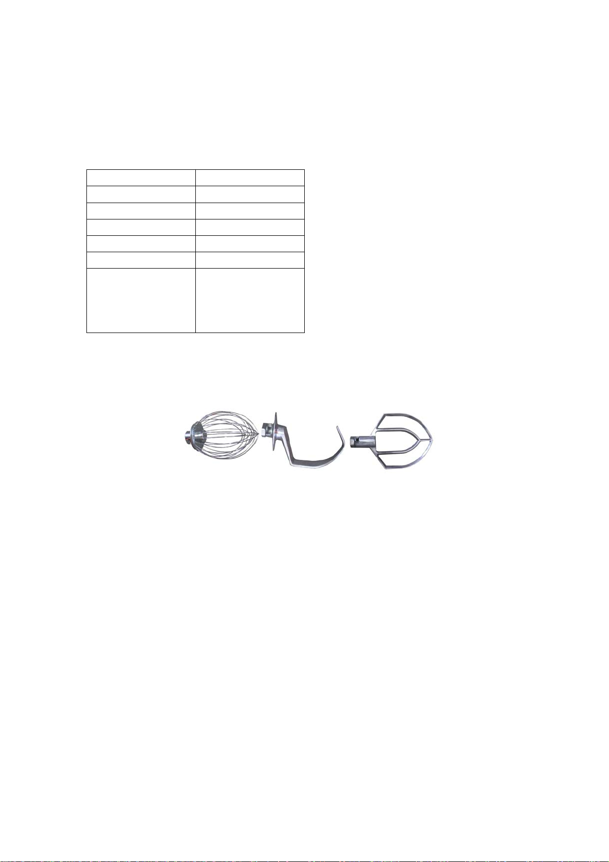
1. SPECIFICATION
Model SM-80L
Capacity 80-quarts
Agitator Speed 133-400rpm
Flour weight 22.5Kg/ 50 pounds
Motor Power 4.5kw
Machine Weight 635Kg/ 1395 pounds
Dimension(W×D×H) 87 × 125 × 175 cm
34 x 50 x 69 inches
2. ATTACHMENT
SM-80L
Whipping Ball Hook Beater
Use of attachment
1) Hook: dough, pastries, pizza, brioches, biscuits, dumplings, stuffing, sausage…etc.
2) Beater: short pastry, chow pastry, royal icing, mixing of meats, mashed potatoes.
3) Whipping Ball: butter cream, whipped cream, ice cream, Fontainebleau (mixture of cottage
cheese and cream), pancakes, mayonnaise and also for finely mashed potatoes using whole
potatoes ( after they have been broken down by beater or hook )
Page 3
3. INSTALLATION
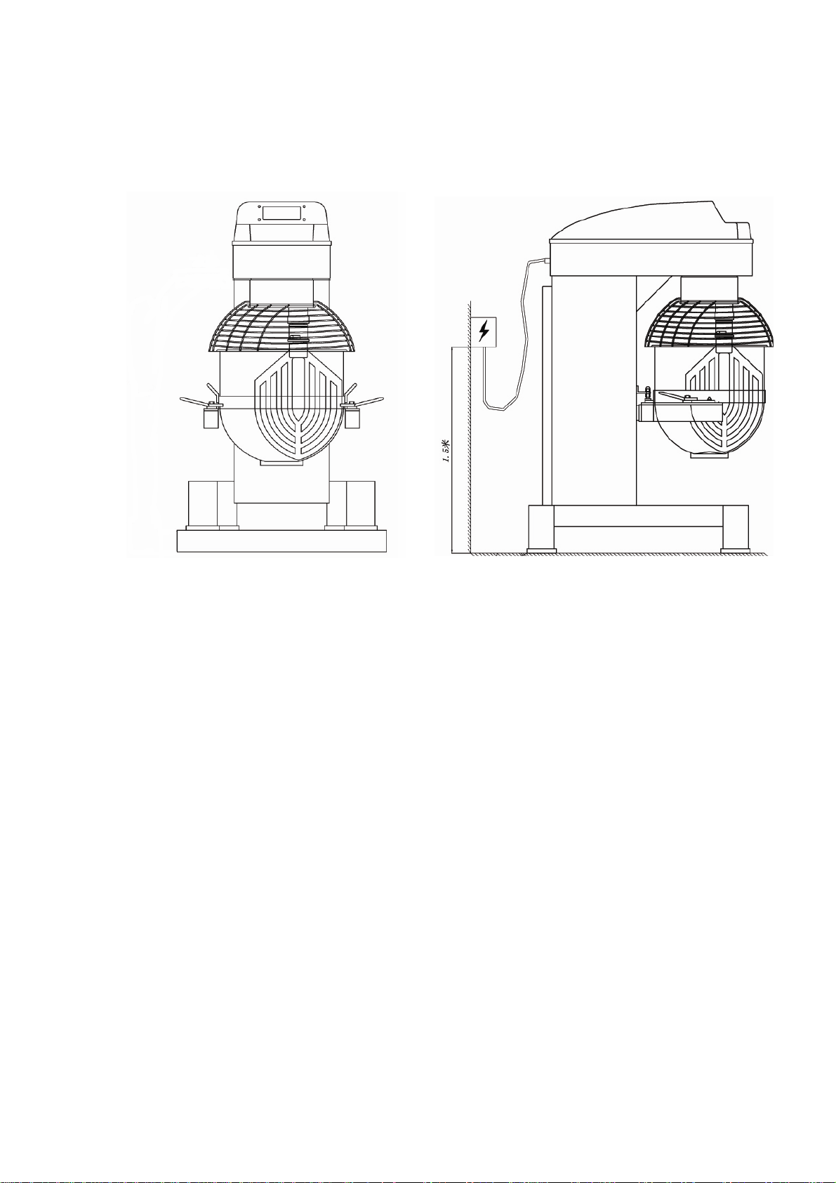
Picture1 Picture2
1) The machine is ready for installation when it arrives. Remove from crating and check for any
damage that may have occurred during transport. Report any damage or missing items
immediately.
2) The machine must be installed on a level floor. If the floor is not level, a rubber mat can be
used to support the machine.
3) Please connect the power supply to the machine as indicated on the nameplate.
4) After the machine has been connected to the electric supply, first of all, check the rotation of
the mixing head. When looking overhead, the mixer head should rotate clockwise. The arrow
on the bowl indicates the proper rotating direction of mixing arm.
Page 4
4. OPERATION
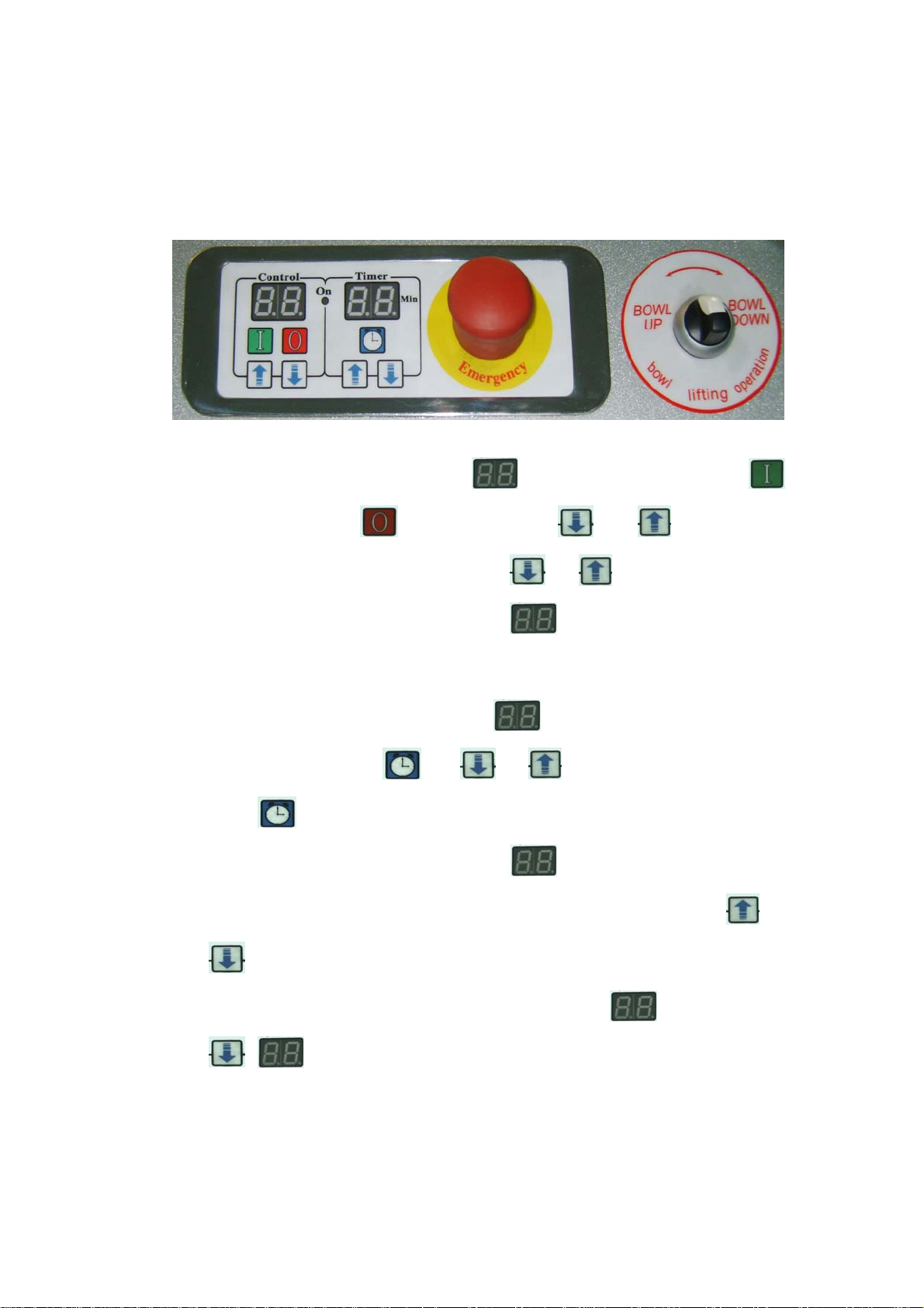
(1) PANEL INSTRUCTION
The right display below the word “control” is the speed display. The green
is the start button, the red
is the stop button, and are the speed
shift buttons. During operation, press the or buttons to reduce or
increase the speed indicated on the display , the number ranges from 01 to 10,
01 is for the slowest speed, 10 is for the fastest speed. You can change speed while the
machine is running (there is no need to stop the machine when changing speeds).
① Th e righ t displ ay belo w the wo rd “timer” is the time display, the number units
are in minutes. The clock
Press
70 minutes. When the number on the display
, “—“ will be displayed, as it is resetting to ‘zero time’. Press the or
again
, and the time on the display will increase by 10 with each push, up to
and or are the timer control buttons.
is 70, if we press the clock button
arrows and the numbers on the display will increase or reduce from 01 to
99 (the number is a multiple of 1), When the number on
is 01, if we press
, will display “--”(no time).
Page 5
② “On” light indicates machine is running. Solid light indicates the machine is
running in un-timed operation. Flashing “ON” light indicates the machine is
running on timer. No light means machine is stopped, and that either the
stop button was depressed or the timer had timed out.
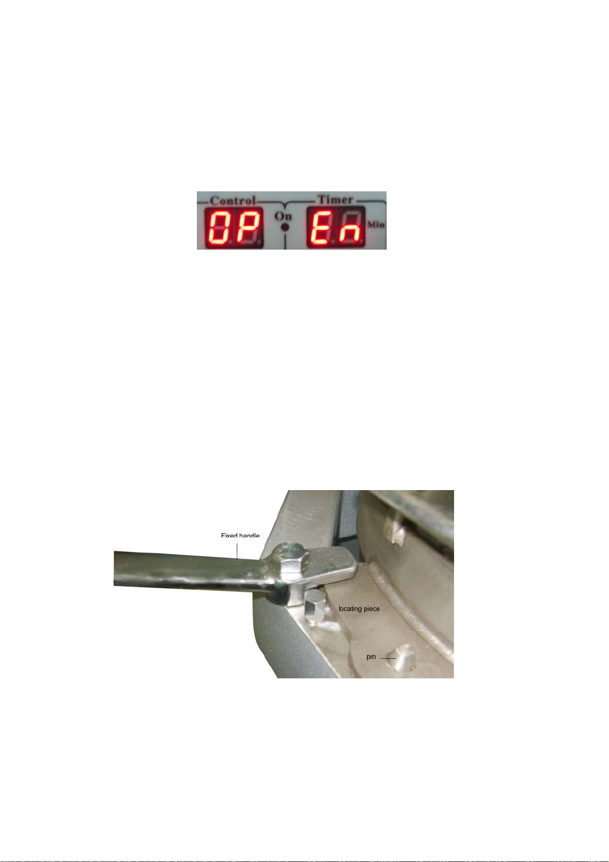
③ If the safety grid is open, or bowl lift is not in the full up position, the display will show
④ Red button is the emergency stop button. By pressing this button the machine and all
functions will stop immediately. To restart the machine, turn the red knob in the
direction of the arrow on the switch and it will release. Then press the green button on
the right side of the machine to restore power to the controls.
⑤ The Black switch is the lift switch. Turn switch to left to lower the bowl lift, and to the
right to raise it. Take care to have the bowl locks UNLOCKED before you lower
bowl onto bowl dolly or damage will result.
OPERATION STEPS
(2)
(1) Turn the lift switch to “down” to lower the bowl to the bottom position.
(2) Insert the pin into the hole of the locating piece on the bowl, and lock the fixed handle.
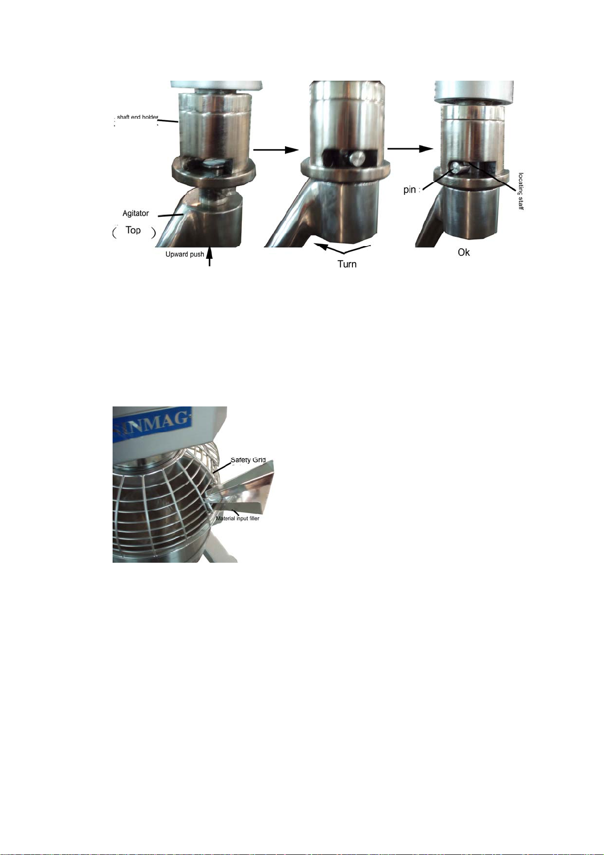
(3) Install the desired attachment (see photo below)
Page 6
(4) Turn the lift switch to “up” to lift the bowl to the top position.
(5) Put the ingredients into the bowl.
(6) Close the bowl safety cover.
(7) Set the mixing speed, mixing time, and turn on the machine.
(8) Choose your speed based on your dough/bat ter properties and desired mixing results.
(9) During operation process, you can put additi onal material into the bowl through filler
chute (see below).
(10) Open the safety grid when the mixing is complete.
(11) Turn the bowl lock handles to loosen the bowl (see picture).
(12) Turn the lift switch to “down” to lower the bowl to the bottom position.
(13) Take out the agitator.
(14) Remove product.
Page 7

5. SAFETY INSTRUCTIONS
(1) Please read this operation manual carefully before operating or maintaining this machine.
Please obey all listed placards and notifications on the machine and in this manual.
(2) Do NOT overload the mixer.
(3) All the safety covers and panels should be closed during operation.
(4) Check operation of all safety switches and safety covers prior to each days use.
(5) Check condition of power cord and plug weekly
(6) Check whether the machine will stop when opening the safety grid or lowering the bowl
(7) All operators should comply with all safety precautions and should not use while
wearing loose clothing or items that could become entangled in mixing arm.
(8) Only the operator of the machine should be near machine while in operation. Operator
should not lean on the machine.
(9)
You must call a qualified technician if there is an electrical problem or broken
.
.
parts on the machine. Contact American Baking Systems for advise or help
with locating a local technician.
(10) Turn power off before maintaining or cleaning machine.
(11) The machine must be grounded at the electrical source.
(12) Turn off the power after daily use. The main switch on the right side of the machine
turns off all power to the unit and is lockable for service.
(13) ONLY use your finger to press buttons on the control panel. Never use tools, knives or
any other objects to push any buttons on ANY control panel.
6. CLEANING AND MAINTENANCE
⑴ Shut the power off at main switch before cleaning the machine!
(2) Use a damp cloth to clean the machine after daily use, do not wash it with a hose or power
washer as this will damage the machine.
(3) Clean the bowl and attachments after each use. Tools and bowl can be machine washed or
sink washed when off of the machine.
(4) Keep the bowl﹑agitator and other parts that come in contact with ingredients clean before
daily use.
(5) Every 2 or 3 months open the access covers and clean the inside of the machine to prevent
flour dust buildup and to check for any foreign items in the machine.
Page 8

① Maintenance
⑴Check all components to see whether they are in good status and the drive belts are tight and in
good condition once a month. There should be a quarter inch of deflection in the center of the
belts between the pulleys when pushed with your finger.
⑵Grease the drive gear wheel, as shown below:
A Loosen three wing nuts, then lift the safety grid up, then turn the safety grid in the direction of
arrow, then ease the bowl cover downward. (see picture above, left), This will uncover an oiling
hole where grease can be added to the planetary.
B Three or four pumps with a grease gun should be sufficient to lube planetary gear and ring.
(see picture above, right)
C Turn on the machine to check the machine while running and listen for any odd noises, If
everything sounds normal, clear excess oil from around the oiling hole with cloth.
D Install the bowl cover safety grid and tighten the wing nuts.
E Every 3 months, open the back cover, grease the worm gear for bowl lift, chain, and other
moving parts on bowl lift.
Page 9
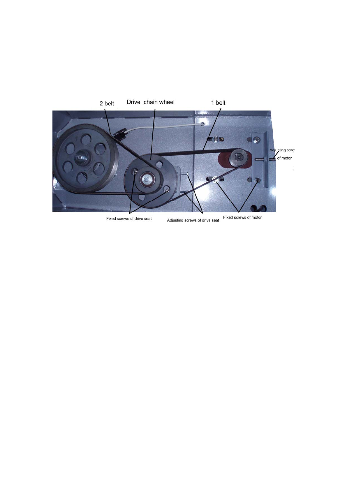
③Belt Adjustment
⑴ During operation, if mixing tool skips, the belt is loose, follow instructions below to repair.
A Turn off the main switch, open the top cover (remark: don’t damage the cables connecting the
top cover and machine). The cover will not come off of machine, place it on a hard surface or
have a helper hold the cover. DO NOT allow top cover to hang off of control wires.
B Loosen the fixed screws of motor and fixed screws of drive seat 2~3 rounds. Do not take
them off. (NOTE: when loosening the fixed screws of drive seat, keep holes of belt wheel in
line with fixed screws of drive seat AS SHOWN ABOVE).
C Turn the adjusting screws of drive seat to adjust the tension of belt 2. Turn screws clockwise
to increase the tension and counter-clockwise is to reduce the tension.
D Tighten the fixed screws of drive seat.
E Turn the adjusting screws of motor to adjust the tension of belt 1. Turn screws clockwise to
increase the tension, and counter-clockwise to reduce the tension.
F Tighten the fixed screws of motor.
G Turn on the machine and listen for any sounds out of the ordinary.
Page 10

n
7. TROUBLESHOOTING
Item Possible reason Method
1.Mixer rotates in reverse
direction.
2.Machine shakes during
operation.
3.The mixer still rotates after
the safety cover has been
opened.
4.Attachments loose or fall
off during mixing.
5. Main shaft does not turn.
6.Main shaft can not stop.
7.Main shaft does not ru
continuously.
8. Electrical short.
Check whether the any of the two cables are
in reverse connection.
a) The floor is not level.
b) Foot pad is unstable (if equipped).
a) There is something wrong with micro
switch.
b) The arm that actuates microswitch is
sticking or dirty.
a) Pin on the attachment is
loose/missing/worn.
b) Machine is rotating in wrong direction.
c) Spring ball on attachment hub stuck. In
up position.
a) Check the power .
b) Check the main switch.
c) Check if the bowl arms are all the way
up.
d) Chec k if any damage on operation panel.
e) Check if contactor pulling in.
f) Check if any overload relay is tripped.
a) Check if any damage on operation
panel.
b) Check the contactor for loose wires or
failed operation.
a) Check for loose wires at contactor.
b) Check if overloads are tripped.
c) Check if any damage on operation panel.
a) Check if any damage on cables.
b) Check if any moisture in electrical box.
c) Check if any damage on wiring of
transformer caused by moisture or other.
Exchange any of the two cables – any of
the two except for ground.
a) Move to a level floor.
b) Readjust the foot pad to restore the
machine’s stability.
a) Change the microswitch.
b) Check the actuator to see if damaged
or dirty. Repair as needed.
a) Replace attachment pin.
b) Switch two electrical leads in plug
until rotation is correct.
c) Loosen spring ball and oil with
mineral oil.
Contact the factory for further instructions.
Contact the factory for further instructions.
Contact the factory for further instructions.
Contact the factory for further instructions.
Page 11

9. Main shaft will stop
y
unexpectedly.
10.Strange noise made b
motor.
reasons.
d) Check if any electric shorts on motor.
a) Check setting on overload protection on
motor.
b) Check if there is anything abnormal on
motor.
c) Check if there is something wrong with
operation panel.
a) Check if there is enough water in the
dough.
b) Check if the noise is made by motor
bearing or belts.
Contact the factory for further instructions.
Contact the factory for further instructions.
Page 12
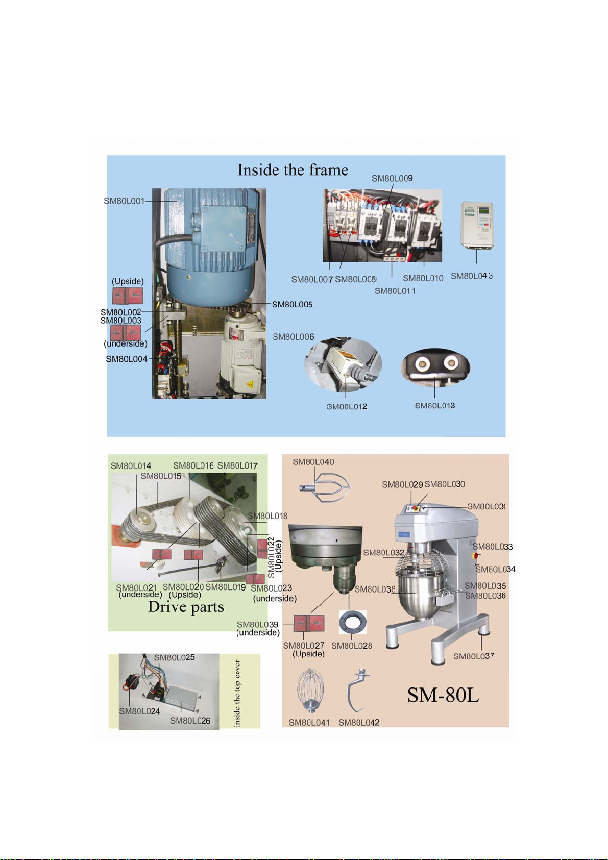
8. PARTS LIST
Page 13

SM-80L PLANETARY MIXER PARTS LIST
Parts List Parts Code Parts Name Specification
SM80L001
16MDL80L-1 Motor
SM80L002 15ZCL51104VV Bearing
SM80L003 15ZCL6004VV Bearing
SM80L004 14SM80L-20 Screw
SM80L005 15LTL415H-55 Chain
SM80L006 16JSJ80L Motor
SM80L007 16DZP280101 Plate
SM80L008 16JDQJZX-18FF-1 Auxiliary relay
SM80L009 16JCQCN16-2 Electromagnetic contactor
SM80L010 16JCQCN18-3 Electromagnetic contactor
380V-50Hz-3PH
51104VV
60042RS
380v 3PH
220V 50Hz
220V 50Hz
SM80L011 16JDQRHN10A-11 Thermal relay
SM80L012 16KGLTZ8108 Micro Switch
SM80L013 16KGLTM1307 Micro Switch
SM80L014 14SM80L-17E Small belt wheel
SM80L015 15PDL1090 Belt
SM80L016 14SM80L-70E Drive belt wheel
SM80L017 15PDL1180 Belt
SM80L018 14SM80L-16E Large belt wheel
SM80L019 16KGLTM1307 Micro Switch
SM80L020 15ZCL6306VV Bearing
7M-1090
6306VV
Page 14

SM80L021 15ZCL6207VV Bearing
6207VV
SM80L022 15ZCL3308AVV Bearing
SM80L023 15ZCL3309AVV Bearing
SM80L024 16KGLM22 Lift switch
SM80L025 16ANL03 Emergency switch
SM80L026 16MBLOMX-022-T2 Panel
SM80L027 15ZCL6207VV Bearing
SM80L028 15YFL456810 Oil seal
SM80L029 16MBLOMX-022-T2 Panel
SM80L030 16ANL03 Emergency switch
SM80L031 16KGLM22 Lift switch
SM80L032 11SM80L-48 Safety grid
SM80L033 16KGL3P20A Main switch
3308AVV
3309AVV
TC45*68*10
SM80L034 16ANL04 Start button
SM80L035 14SM60L-33-02 Press handle(left)
SM80L036 14SM60L-33-03 Press handle(right)
SM80L037 14SM60L-23 Rubber mat
SM80L038 11SM80L-29 Kneading bowl
SM80L039 15ZCL6008VV Bearing
SM80L040 13SM80L-99 Beater
SM80L041 14SM80L-100 Whipping ball
SM80L042 11SM80L-98 Hook
SM80L043
16BPQ80L-1 Transducer 7200MA 220V5.5KW
Page 15
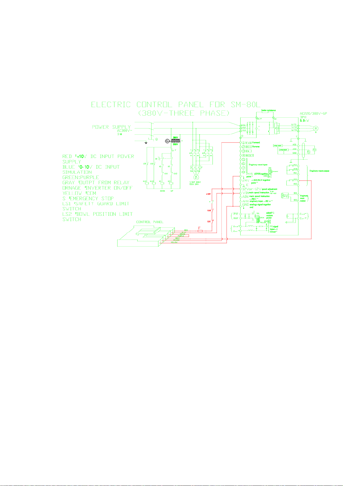
9.ELECTRIC DIAGRAM
 Loading...