

American Audio VLP User Manual
Professional Power Amplifier
AMERICAN AUDIO®
4295 Charter Street
Los Angeles Ca. 90058
Rev. 2/06
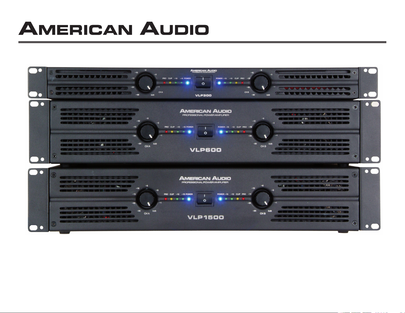
VLP Series
User Instructions

This symbol is intended to alert the user to the presence of non insulated "dangerous voltage" within the product's enclosure that may be of sufficient magnitude to
constitute a risk of electric shock to persons.
This symbol is intended to alert the user of the presence of important operating and maintenance (servicing) instructions in the literature accompanying the product.
CAUTION: Risk of the electrical shock - DO NOT OPEN!
CAUTION: To reduce the risk of electrical shock, do not remove cover. No user serviceable parts inside. Refer all servicing to qualified service personnel.
WARNING: To prevent electrical shock or fire hazard, do not expose this amplifier to rain or moisture. Before using this amplifier, read the user manual for further warnings.
Este símbolo tiene el propósito de alertar al usuario de la presencia de “voltaje peligroso“ que no tiene aislamiento dentro de la caja del producto que puede tener
una magnitud suficiente como para constituir riesgo de corrientazo.
Este símbolo tiene el propósito de alertar al usuario de la presencia de instrucciones importantes sobre la operación y mantenimiento en la literatura que vienc con
el producto.
PRECAUCIÓN: Riesgo del choque eléctrico - NO SE ABRA
PRECAUCIÓN: Para disminuir el riesgo de choque eléctrico, no quite la cubierta. No hay piezas adentro que el usario puede reparar. Deje todo mantenimiento al los téc-
nicos cualificados.
ADVERTENCIA: Para prevenir choque eléctrico o riesgo de incendios, no deja expuesto a la lluvia o a la humedad este amplificador. Antes de usar este amplificador, lea
mas advertencias en la guia de operacion.
Ce symbole est utilisé pur indiquer à l’utilisateur la présence à l'intérieur de ce produit de tension non-isolée dangereuse pouvant être d'intensité suffisante pour
constituer un risque de choc électrique.
Ce symbole est utilisé pour indiquer à l’utilisateur qu'il trouvera d'importantes instructions importantes sur l'utilisation et l'entretien de l'appareil dans la littérature
accompagnant le produit.
ATTENTION:
Risque de choc électrique - NE PAS OUVRIR!
ATTENTION: Afin de réduire le risque de choc électrique, ne pas enlever le couvercle. Il ne se trouve à l’intérieur aucune piéce pouvant être réparée par l'utilisateur. Confier
l'entretien à un personnel qualifié.
AVERTISSEMENT: Afin de prévenir les risque de décharge ou de feu, n’exposez pas cet appareil à la pluie ou à l’humidité. Avant d’utiliser cet amplificateur, lisez les avertissements supplémentaries situés dans le guide.
Dieses Symobl soll den Anwender vor unisollierten gefährlichen Spannungen innerhalb des Gehäuses warnen, die von Ausreichender Stärke sind, um einen elektrischen Schlag verursachen zu können.
Dieses Symobl soll den Benutzer auf wichtige Instruktionen in der Bedienungsanleitung aufmerksam machen, die Handhabung und Wartung des Produkts betref
-
fen.
VORSICHT: Risiko - Elektrischer Schlag! Nicht öffnen!
VORSICHT: Um ddas Risiko eines elektrischen Schlages zu vermeiden, nicht die Abdeckung enfernen. Es befinden sich keine Teile darin, die vom Anwender repariert
werden könnten. Reparaturen nur von qualifizierte Fachpersonal durchführen lassen.
ACHTUNG: Um einen elektrischen Schlag oder Feuergefahr zu vermeiden, sollte diesen Gerät nicht dem Regen oder Feuchtigkeit ausgesetz werden. Vor Inbetriebnahme
unbedingt die Bedienungsanleitung lesen.
©American Audio® - www.americanaudio.com - VLP Series™ Power Amplifier User Manual Page 2
CAUTION
Do not open -
risk of electric shock
CAUTION: TO REDUCE THE RISK OF ELECTRIC
SHOCK, DO NOT REMOVE THE COVER.
THERE ARE NO USER SERVICEABLE PARTS
INSIDE. REFER ALL SERVICE TO YOUR
AUTHORIZED AMERICAN AUDIO® DEALER.
The lightning flash with an arrow triangular
symbol is intended to alert the user to the
presence of non insulated “dangerous volt
age” within the products enclosure, and
may be of sufficient magnitude to consti
tute a risk of electric shock.
The exclamation point triangular symbol is
intended to alert the user to the presence
of important operating and maintenance
(servicing) instructions in the user manual
accompanying the amplifier.
FOR OPTIMUM PERFORMANCE AND
RELIABILITY DO NOT PRESENT THE
AMPLIFIER WITH A SPEAKER LOAD
OF LESS THAN 2 OHMS OR ANY
COMBINATION OF SPEAKERS THAT
TOGETHER ARE LESS THAN 2 OHMS!
USING ONE SPEAKER, IT MUST BE
-
RATED AT 4 OR MORE OHMS.
-
USING TWO SPEAKERS, THEY MUST
RATED EACH AT 4 OR MORE OHMS.
USI NG THR EE SPE AK ERS , T HEY
MUST BE RATED EACH AT 8 OR MORE
OHMS.
P O U R A S S U R E R L A F I A B I L E T E E T
OBTENIT UNE PERFORMANCE OPTIMALE,
NESOUMET TE JAM A IS L’AMPLIFICATEUR
A U NE C HARG E D’I MPEDANCE TOTALE
INFERIEURE A 2 OHMS, NI AVEC UN H.P. NI
EN COMBINAISON DES H.P.
AV EC UN H. P., I L FAU T UNE CHA RGE
D’IMPEDANCE MINIMUM DE 2 OHMS.
AVEC DEUX H.P., FAUT POUR CHAOUN UNE
CHARG E D’IMPEDANCE MINIM U M DE 4
OHMS.
AVEC TROIS H.P., FAUT POUR CHAOUN UNE
CHURGE D’IMPEDA NCE MI N IMUM DE 8
OHMS.
CONTENTS:
Safety Precautions.......................................................................................................................................................................................4
Introduction...............................................................................................................................................................................................4
Front Panels.................................................................................................................................................................................................5
Rear Panels..................................................................................................................................................................................................7
Inputs...........................................................................................................................................................................................................9
Outputs............................................................................................................................................................................................................9
Speakon Output Connector Assembly.......................................................................................................................................................11
Operating Modes........................................................................................................................................................................................12
Protection Circuitry
Limiter.................................................................................................................................................................................................13
Short Circuit Protection...................................................................................................................................................................13
Thermal Protection..........................................................................................................................................................................14
Amplifier Features.......................................................................................................................................................................................14
Speaker Setup............................................................................................................................................................................................15
Warranty.................................................................................................................................................................................................16
Specifications...............................................................................................................................................................................................17
©American Audio® - www.americanaudio.com - VLP Series™ Power Amplifier User Manual Page 3

Important Precautions
Introduction
• To reduce the risk of electrical shock or fire, do not expose this
unit rain or moisture.
• Do not spill water or other liquids into or on to your unit.
• Do not attempt to operate this unit if the power cord has been
frayed or broken.
• Do not attempt to remove or break off the ground prong from
the electrical cord. This prong is used to reduce the risk of elec trical shock and fire in case of an internal short.
• Disconnect main power before making any type of connection
• Do not remove the cover under any conditions. There are no
user serviceable parts inside.
• Never plug this unit in to a dimmer pack.
• Always be sure to mount this unit in an area that will allow
proper ventilation. Allow about 6” (15cm) between this device
and a wall.
• Do not attempt to operate this unit, if it becomes damaged.
• This unit is intended for indoor use only, use of this product out doors voids all warranties.
• During long periods of non-use, disconnect the unit’s main
power.
• Always mount this unit in a safe and stable manner.
• Power cords should be routed so they are not likely to be
walked on, pinched by items placed upon or against them.
• Cleaning -The outside of the unit should be wipe down with a
soft cloth and mild cleaner when needed.
• Heat -The appliance should be situated away from heat sources
such as radiators, heat registers, stoves, or other appliances
(including amplifiers) that produce heat.
• The fixture should be serviced by qualified service personnel
when:
A. The power-supply cord or the plug has been damaged.
B. Objects have fallen on, or liquid has been spilled into the unit.
C. The appliance has been exposed to rain or water.
D. The fixture does not appear to operate normally or exhibits a
marked change in performance.
©American Audio® - www.americanaudio.com - VLP Series™ Power Amplifier User Manual Page 4
Introduction: Congratulations and thank you for purchasing
this American Audio
representation of American Audio’s continuing commitment to
produce the best and highest quality products all at an affordable
price. Please read and understand this manual completely before
attempting to operate your new amplifier. This booklet contains
important information concerning the proper and safe operation of
your new amplifier.
Unpacking:
tested and has been shipped in perfect operating condition.
Carefully check the shipping carton for damage that may have
occurred during shipping. If the carton appears to be damaged,
carefully inspect your unit for any damage and be sure all acces
sories necessary to operate the unit has arrived intact. In the event
damage has been found or parts are missing, please contact our
toll free customer support number for further instructions. Please
do not return the amplifier to your dealer without contacting cus
tomer support first.
Installation: This amplifier is designed to mount into a standard
19” rack. The front panel provides four holes used to screw the
unit into a rack. The unit also provides a way to rear mount the
unit into a rack for added security. Rear mounting the unit is espe
cially recommended for this amplifier if the unit is to mounted into
a mobile rack.
Customer Support: American Audio
er support line, to provide set up help and to answer any question
should you encounter problems during your set up or initial opera
tion. You may also visit us on the web at www.americanaudio.com
for any comments or suggestions. For service related issue please
contact American Audio
Friday 9:00 a.m. to 5:00 p.m. Pacific Standard Time.
Voice: (800) 322-6337 E-mail: support@americanaudio.com
Fax: (323) 582-2610
Every VLP Series™ amplifier has been thoroughly
® VLP series™ amplifier. This amplifier is a
-
-
-
® provides a toll free custom-
-
®. Service Hours are Monday through
PROFESSIONAL POWER AMPLIFIER
VLP1500
PRO CLIP POWER
10
15
CH A
0 dB
10
6
3
1
80
30
15
PROCLIPPOWER
10
15
CH B
0 dB
10
6
3
1
80
30
15
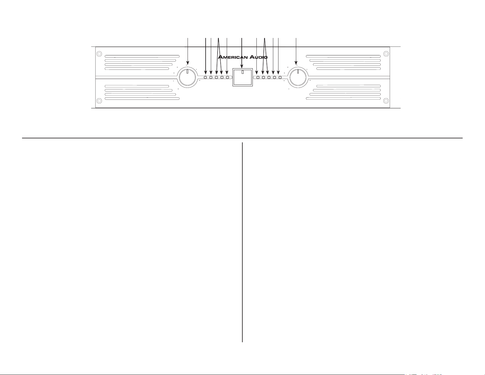
Front Panel
VLP600 & VLP1500
1 109875432 6 5
Figure 1
1. Channel 1 Gain Control - This rotary knob is used to control the output signal of channel one. Turning the knob in a clockwise direction will
increase signal output.
2. Channel 1 Protect Indicator - The red Protect LED will begin to glow
when the channel goes into protect mode. When the channel goes into
protect mode all output for that channel will turn off. This is to protect any
speakers connected to the channel.
3. Channel 1 Clip Indicator - This red LED will begin to flash when
channel one begins to overload (clip). At this point channel one will begin to distort. Under heavy clipping activity lower the channel one gain
control to reduce the risk of damage to your speakers and amplifier. This
LED may glow when the unit has been turned off, this is normal.
4. Channel 1 Signal Indicators - These green and yellow LED’s will glow
according to the average signal output.
5. Function Indicators - These indicators detail the operating mode of
the amplifier. These LEDs will also function as a power indicator.
6. Power Switch - This switch is used to control the units main power.
7. Channel 2 Signal Indicators - These green and yellow LED’s will glow
according to the average signal output.
control to reduce the risk of damage to your speakers and amplifier. This
LED may glow when the unit has been turned off, this is normal.
9. Channel 2 Protect Indicator - The red Protect LED will begin to glow
when the channel goes into protect mode. When the channel goes into
protect mode all output for that channel will turn off. This is to protect any
speakers connected to the channel.
10. Channel 2 Gain Control - This rotary knob is used to control the
output signal of channel two. Turning the knob in a clockwise direction
will increase signal output.
8. Channel 2 Clip Indicator - This red LED will begin to flash when
channel one begins to overload (clip). At this point channel one will be
gin to distort. Under heavy clipping activity lower the channel one gain
©American Audio® - www.americanaudio.com - VLP Series™ Power Amplifier User Manual Page 5
-
PROFESSIONAL POWER AMPLIFIER
VLP300
PRO
CH A
CLIP
POWER
0 dB
10
15
10
6
3
1
80
30
15
POWER
15
10
CLIP
PRO
CH B
0 dB
10
6
3
1
80
30
15
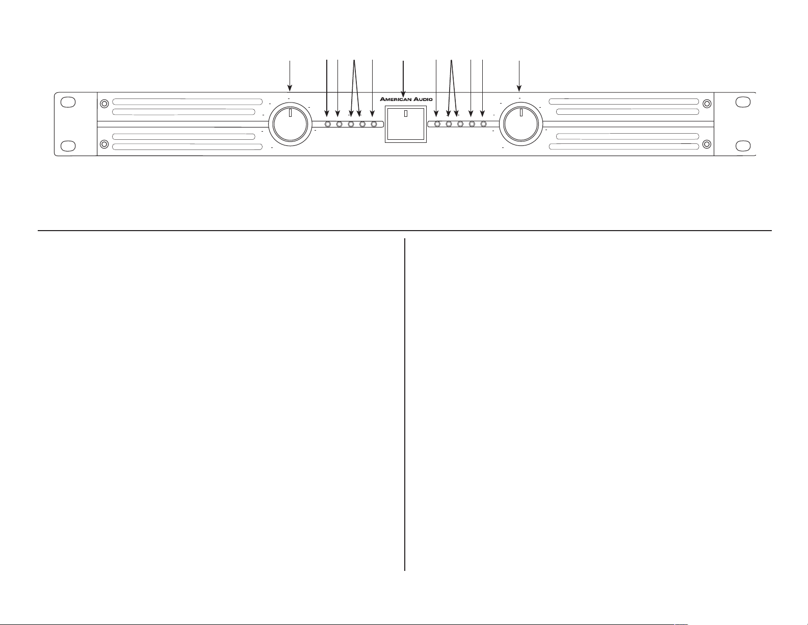
Front Panel
VLP300
11 20191815141312 16 1715
Figure 2
11. Channel 1 Gain Control - This rotary knob is used to control the
output signal of channel one. Turning the knob in a clockwise direction
will increase signal output.
12. Channel 1 Protect Indicator - The red Protect LED will begin to
glow when the channel goes into protect mode. When the channel goes
into protect mode all output for that channel will turn off. This is to protect any speakers connected to the channel.
13. Channel 1 Clip Indicator - This red LED will begin to flash when
channel one begins to overload (clip). At this point channel one will begin to distort. Under heavy clipping activity lower the channel one gain
control to reduce the risk of damage to your speakers and amplifier. This
LED may glow when the unit has been turned off, this is normal.
14. Channel 1 Signal Indicators - These green and yellow LED’s will
glow according to the average signal output.
15. Power Indicators - These LEDs function as a power indicator.
16. Power Switch - This switch is used to control the units main power.
17. Channel 2 Signal Indicators - These green and yellow LED’s will
glow according to the average signal output.
18. Channel 2 Clip Indicator - This red LED will begin to flash when
channel one begins to overload (clip). At this point channel one will begin to distort. Under heavy clipping activity lower the channel one gain
control to reduce the risk of damage to your speakers and amplifier. This
©American Audio® - www.americanaudio.com - VLP Series™ Power Amplifier User Manual Page 6
LED may glow when the unit has been turned off, this is normal.
19. Channel 2 Protect Indicator - The red Protect LED will begin to
glow when the channel goes into protect mode. When the channel goes
into protect mode all output for that channel will turn off. This is to protect any speakers connected to the channel.
20. Channel 2 Gain Control - This rotary knob is used to control the
output signal of channel two. Turning the knob in a clockwise direction
will increase signal output.
 Loading...