

Page 1
AMERICAN AUDIO
®
4295 Charter Street
POW ER
ON
OFF
LIM ITER
ON
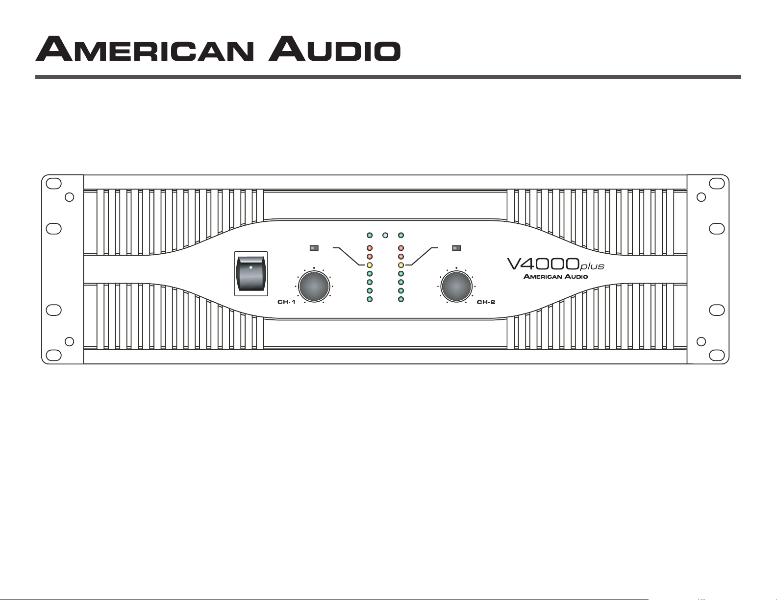
PROFESSIONAL POWER AMPLIFIER
LIM ITER
ON
MONO STER EO BRID GE
-15d B
SIGN AL
-10d B
-5dB
CLIP
PROT ECT
OVER HEAT
0
10
0
10
Page 2

This symbol is intended to alert the user to the presence of non insulated "dangerous voltage" within the product's enclosure that may be of suf cient magnitude to
This symbol is intended to alert the user of the presence of important operating and maintenance (servicing) instructions in the literature accompanying the product.
Risk of the electrical shock -
To reduce the risk of electrical shock, do not remove cover. No user serviceable parts inside. Refer all servicing to quali ed service personnel.
To prevent electrical shock or re hazard, do not expose this ampli er to rain or moisture. Before using this ampli er, read the user manual for further warnings.
ATTENTION:
Risque de choc électrique -
NE PAS OUVRIR!
ATTENTION:
Afin de réduire le risque de choc électrique, ne pas enlever le couvercle. Il ne se trouve à l’intérieur aucune piéce pouvant être réparée par l'utilisateur. Confier
AVERTISSEMENT:
Afin de prévenir les risque de décharge ou de feu, n’exposez pas cet appareil à la pluie ou à l’humidité. Avant d’utiliser cet amplificateur, lisez les aver-
tissements supplémentaries situés dans le guide.
ATTENTION:
ATTENTION:
AVERTISSEMENT:
PRECAUCIÓN:
PRECAUCIÓN:
ADVERTENCIA:
PRECAUCIÓN:
ADVERTENCIA:
trischen Schlag verursachen zu können.
fen.
Risiko - Elektrischer Schlag! Nicht öffnen!
Um ddas Risiko eines elektrischen Schlages zu vermeiden, nicht die Abdeckung enfernen. Es be nden sich keine Teile darin, die vom Anwender repariert
werden könnten. Reparaturen nur von quali zierte Fachpersonal durchführen lassen.
ACHTUNG:
Um einen elektrischen Schlag oder Feuergefahr zu vermeiden, sollte diesen Gerät nicht dem Regen oder Feuchtigkeit ausgesetz werden. Vor Inbetriebnahme
ACHTUNG:
©American Audio® - www.americandj.com - V4000plus™ Power Amplifier User Manual Page 2
Page 3
THERE ARE NO USER SERVICEABLE PARTS
AUTHORIZED AMERICAN AUDIO
®
CAUTION
AMPLIFIER WITH A SPEAKER LOAD
TOGETHER ARE LESS THAN 2 OHMS!
The lightning flash with an arrow triangular
tute a risk of electric shock.
The exclamation point triangular symbol is
A UNE CHARGE D’IMPEDANCE TOTALE
AVEC UN H.P., IL FAUT UNE CHARGE
AVEC DEUX H.P., FAUT POUR CHAOUN UNE
AVEC TROIS H.P., FAUT POUR CHAOUN UNE
Thermal Protection...........................................................................................................................................................................11
©American Audio® - www.americandj.com - V4000plus™ Power Amplifier User Manual Page 3
Page 4
Important Precautions
To reduce the risk of electrical shock or re, do not expose this
frayed or broken
the electrical cord. This prong is used to reduce the risk of elec-
trical shock and re in case of an internal short
Always be sure to mount this unit in an area that will allow
This unit is intended for indoor use only, use of this product out-
Always mount this unit in a safe and stable manner
walked on, pinched by items placed upon or against them.
The fixture should be serviced by qualified service personnel
when:
A. The power-supply cord or the plug has been damaged.
marked change in performance.
Introduction
the American Audio
®
V4000
plus™
amplifier. This amplifier is a
plus™
ampli er has been thoroughly
tested and has been shipped in perfect operating condition.
tact our toll free customer support number for further instructions.
This amplifier is designed to mount into a standard
American Audio
®
provides a toll free custom-
tion. You may also visit us on the web at www.americandj.com for
®
Voice:
©American Audio® - www.americandj.com - V4000plus™ Power Amplifier User Manual Page 4
Page 5
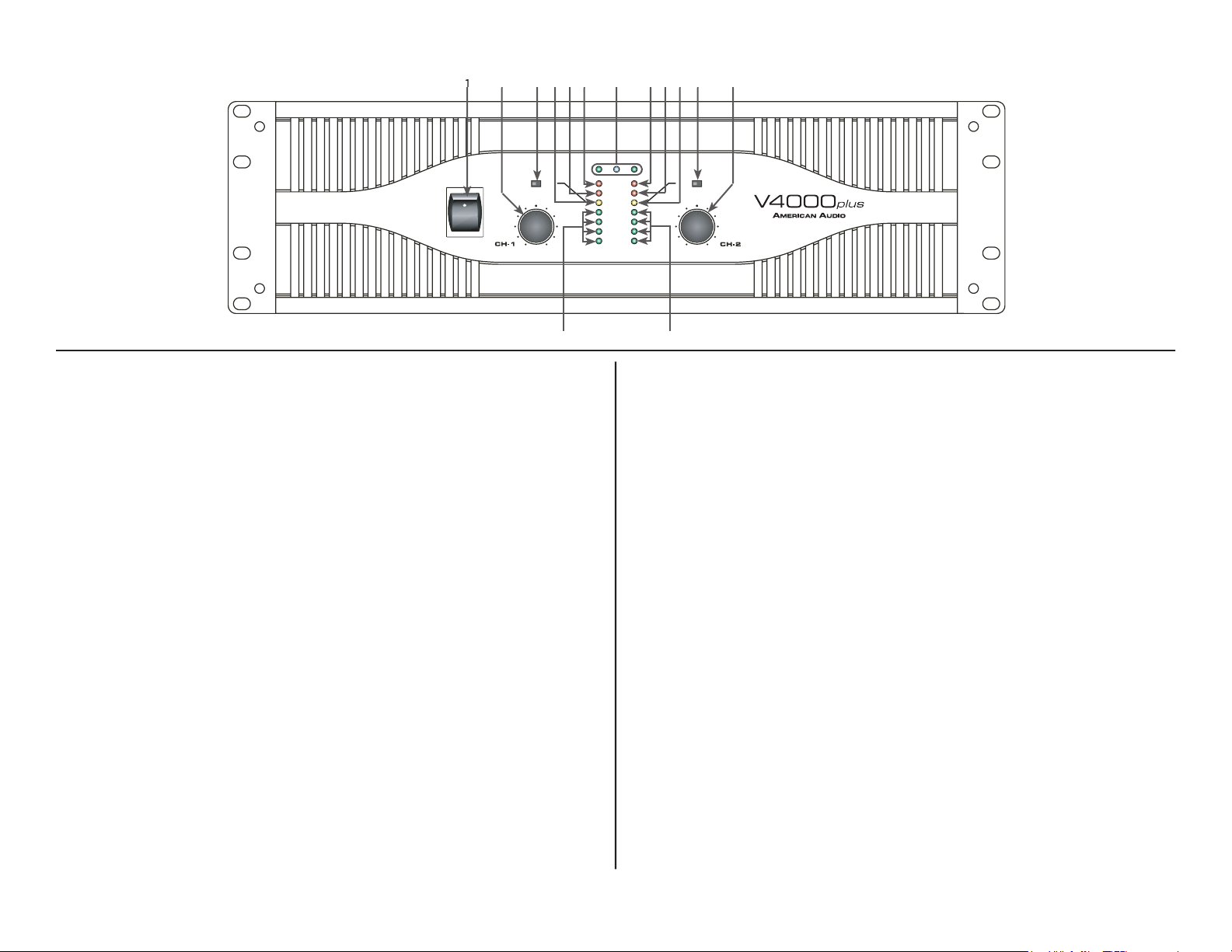
This switch is used to control the units main power.
2. Channel 1 Gain Control -
This rotary knob is used to control the out-
3. Channel 1 Limiter Switch -
This is used to activate the channels
4. Channel 1 Clip Indicator -
This red LED will begin to ash when
5. Channel 1 Protect Indicator -
The red Protect LED will begin to glow
when the channel goes into protect mode. When the channel goes into
6. Channel 1 Overheat Indicator -
This indicator will begin to glow
when the channel goes into thermal protection mode. When the unit
These green and yellow LED’s will glow
©American Audio® - www.americandj.com - V4000plus™ Power Amplifier User Manual Page 5
Front Panel Control
POWE R
ON
OFF
LIMI TER
ON
PROFESSIONAL POWER AMPLIFIER
LIMI TER
ON
MONO STE REO BRIDG E
-15dB
SIGNAL
-10dB
-5dB
CLIP
PROTEC T
OVER HE AT
0
10
0
10
943
2
8. Function Indicators -
These indicators detail the operating mode of
the ampli er. These LEDs will also function as a power indicator.
9. Channel 2 Overheat Indicator -
This indicator will begin to glow
when the channel goes into thermal protection mode. When the unit
The red Protect LED will begin to
tect any speakers connected to the channel.
This red LED will begin to ash when
This is used to activate the channels
This rotary knob is used to control the
will increase signal output.
These green and yellow LED’s will
Page 6

32
33
Rear Panel Control
ther a balanced or unbalanced plug. See page 7 for more details.
Turns the subwoofer
This knob is used to adjust the
frequency level sent to your speaker on channel two when running the
20. Channel 1 XLR input -
21. Channel 1 Frequency Adjustment -
This knob is used to adjust the
frequency level sent to your speaker on channel one when running the
22. Channel 1 TRS Input -
ther a balanced or unbalanced plug. See page 7 for more details.
23. Channel 1 Subwoofer Mode On/Off Switch -
Turns the subwoofer
24. Channel 2 XLR THRU Jack -
This jack is used to send a parallel
25. Mode Switch -
This switch controls the ampli er’s operating mode.
The ampli er can operate in three different modes; Mono Bridge, Parallel
26. Channel 1 XLR THRU Jack -
This jack is used to send a parallel
27. Fuse Holder -
This holder houses the external 20 amp fuse. Always
®
28. Channel 2 Speakon Output -
29. Channel 1 Speakon Output -
30. Channel 2 Output Jack/5 way Binding Post -
31. Channel 1 Output Jack/5 way Binding Post -
32. Ground Lift Switch -
This switch is used to disconnect the internal
33. AC Cord -
©American Audio® - www.americandj.com - V4000plus™ Power Amplifier User Manual Page 6
Page 7

Hot (+)
Ne
gati
ve
(-)
Diagram 5
Plug
Ground/Shield
Hot (+)
Ne
gati
ve
(-)
Diagram 4
gati
v
e (- data)
2
3
gu
Diagram 3
Connect your speakers to the binding post outputs on the rear of the ampli er. The
Important Notice:
Although a speaker will operate with the positive and negative leads plugged into either termi-
the red terminal. Ensuring proper polarity will avoid speakers being out of phase, that can cause a loss of bass
Important Notice:
jack is inserted securely to avoid the risk of it popping out.
Set Up
- The V4000
plus
amplifier allows you to use two types of input connector per a channel, a XLR jack for balanced connections
plus
amplifier. A balanced connection is recommended for cable runs longer that 20ft. When
to jump a parallel connection to another amplifier or other device. For Example: Connect a XLR cable to the input of channel one. You
will reduce the use of “Y” cables.
©American Audio® - www.americandj.com - V4000plus™ Power Amplifier User Manual Page 7
Page 8

When connecting your speakers to the amplifier using bare wire; Unscrew the red and black
that of another.
When connecting your speakers to the amplifier using spade connector; Unscrew the red and black caps on
the binding post, be sure not to completely remove or unscrew the red and black caps. Insert the spade con-
with that of another.
When connecting your speakers to the amplifier using banana jacks; Be sure that the red and black caps on
the binding post are tighten down completely. Insert the banana jacks into the caps of the binding post, be
Typical speaker output using bare wire. Insert
Typical speaker output using
®
to the speaker. The Speakon connector used on this ampli er meets all known safety regulations. Once wired correctly, the connector
®
©American Audio® - www.americandj.com - V4000plus™ Power Amplifier User Manual Page 8
Page 9

Always configure your amplifier operating mode before beginning operation. If you want to change it dur-
Stereo Operation -
Page 10/Figure 9 details an example of a typical stereo set-up. Connect your inputs into channels one and
two of the amplifier. Connect your speakers to the outputs on the rear of the amplifier. Be sure that your front gain controls are turned
Mono Bridge Operation -
Page 9/Figure 8 details a mono bridge set-up. Be sure your amplifier and all other audio equipment
your speaker across the red output binding post on the rear of your amplifier. Turn your equipment on (your amplifier should always
Bridged-Mono Mode Caution -
The voltage across the output terminals of a bridged V4000
plus™
amplifier may equal or exceed
Parallel Mono -
V4000
plus
to run bass
Subwoofer Mode -
This mode sends low frequencies to your speakers without the use of an external cross-over. The subwoofer
Bridge Subwoofer -
This operation allows you to get the most possible power out of your ampli er for the sole purpose of running a
this mode you may use the frequency adjustment on the rear of the amp, to control the frequency output level. Frequencies may be
Stereo Subwoofer -
This operation is similar to the Bridge Subwoofer operation but in stereo. This operation allows you to run several
frequency adjustment on the rear of the amp, to control the bass frequency output level. Frequencies may be adjusted from 20Hz to
©American Audio® - www.americandj.com - V4000plus™ Power Amplifier User Manual Page 9
Page 10

Mono Subwoofer -
This operation is similar to the Stereo Subwoofer operation but in mono. When running subwoofers it is usually
You may also use your amp to bi-amp your system. You may use one
Limiter -
The V4000
plus™
series comes with a built in limiter. When the input signal overloads, the “CLIP LED’s” indicate a signal
Safe Power Levels at Different Output Loads:
8-Ohm Loads:
The amplifier can operate at practically any power level without risk of overheating. However, if it is pushed hard
4-Ohm Loads:
If the “CLIP” indicator flashes occasionally, the amplifier is approaching its maximum long-term power capacity. If it is
2-Ohm Loads:
Except for an occasional flash, keep the “CLIP” indicator dark to avoid overheating the amplifier channel. Clipping
Short Circuit Protection -
The V4000
plus™
series amplifiers all come with built-in Output Short
from short circuits and stressful loads. If your speaker lines short, the amplifier automatically detects
this problem and discontinues operation for that channel. If one side of your amplifier becomes
fault. All channel output during the “Short Circuit Protection" will be interrupted (i.e. no sound out-
©American Audio® - www.americandj.com - V4000plus™ Power Amplifier User Manual Page 10
Page 11

Short Circuit Protection
can usually be traced back to the signal output line (i.e. speaker line). Check the line from the output
terminal of the amplifier to the speaker. If this line good, check the internal speaker connections and components. A short circuit will
plus
amplifier provide adequate cooling. During low level output the fans
Input/Output Protection -
The input circuits are isolated by 10k resistors. An ultrasonic network uncouples
from the output and
The serial number label indicates the correct AC main voltage. Connecting to the wrong voltage is
The gain controls are located on the front panel and are calibrated in 2dB of attenuation from full gain. It is best to
AMPLIFIER FEATURES:
Thru will allow the user to daisy-chain one amplifiers signal input into another amplifier. Plug the signal source outputs into the
first amplifier’s input, patch from the amplifier’s THRU jacks to the next amplifier’s input, and so on, daisy-chaining as many amplifiers
Applying or lifting the ground switch will change the level for background noise and hum, if the noise level
that is sometimes induced when mounting several units in the same rack.
The serial number label indicates the correct AC main voltage. Connecting to the wrong voltage
The gain controls are located on the front panel and are calibrated in 2dB of attenuation from full gain. It is best to
LED INDICATORS -
FUNCTION INDICATORS
©American Audio® - www.americandj.com - V4000plus™ Power Amplifier User Manual Page 11
Page 12

Two red LED’s for this function, one for each
SPEAKON ASSEMBLY:
You will need a pair of Neutrik Speakon
®
NL4FC
tighten the connection (Figure 12).
wire (Figure 13).
that the large notch on the outer edge of the insert lines up with the large
through the housing and out the other side until it extends approximately 3
/4-inch from the end of the housing.
from the back end of the connector.
UTPUT
S
INPUT BA
ANCE
SPEAKON
1+ HO
1
COL
D
-1
4-Conductor Speaker Cable
A C
©American Audio® - www.americandj.com - V4000plus™ Power Amplifier User Manual Page 12
Page 13

ositiv
©American Audio® - www.americandj.com - V4000plus™ Power Amplifier User Manual Page 13
Page 14

TYPICAL MONO BRIDGE SET-UP
TYPICAL STEREO OUTPUT CONNECTIONS
©American Audio® - www.americandj.com - V4000plus™ Power Amplifier User Manual Page 14
termainals (red) for speaker output.
Page 15

THD
W
W
y Response:
w rated output,
Total Harmonic Distortion:
20Hz-20kHz, @ rated
output power, 8 ohms
Input Sensitivity and
Impedance: @ rated
output power, 8 ohms
Power Consumption: @
rated output power, 8 ohms
American Audio® - www.americandj.com - V4000plus™ Power Amplifier User Manual Page 15
Page 16

American Audio® is part of the American DJ® Group of Companies
American DJ® World Headquarters:
Tel: 323-582-2650 / Fax: 323-582-2610
web: www.americandj.com / e-mail: info@americandj.com
 Loading...