


PhoneLink
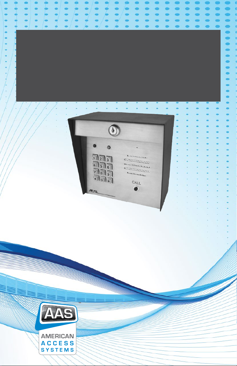
Phonelink
Access Control Station
Installation and
Operating Manual
www.americanaccess.com
“Your Partner in Access Control”

Page 2 American Access Systems / Security Brands, Inc.
Contents
Two-Year Limited Warranty 3
FCC Requirements 3
DOC Requirements 4
Equipment Attachment Limitations 4
Parts Checklist 4
Tools Needed For Basic Installation 4
Technical/Customer Support 5
Introduction 5
Before Installation 5
Important Tips 5
Installation 6
Mounting the unit to an AAS Gooseneck Pedestal (18-001)
or double height Gooseneck (18-003) 6
Installation Steps 6
Wiring the Station 6
PhoneLink Circuit Board Layout 7
General Operating Instructions 9
Receiving Calls – Allowing Access 9
Call Waiting 9
Calling the Gate 9
Intercom (Audio) Mode 9
Indoor Command Code(s) Reference 9
Access and Function Codes 10
Good Tones and Error Tones 10
Resetting the Unit 10
Master Reset 10
Unit Reset 10
Idle Mode 11
The Program Mode 11
The * and # Keys 11
Programming the Gate 11
Sub-Mode 1 (Program Relay A Access Codes) 11
Sub-Mode 2 (Delete Codes) 11
Sub-Mode 3 (Change MASTER Code) 12
Sub-Mode 4 (Set Sleep Code & Latch Code and/or Call Forwarding) 12
Set Latch Code 12
(MASTER CODE) + 4 + 2 + LATCH CODE 12
Call Forwarding 12
Sub Mode 4 (Call Forwarding) 12
Sub-Mode 5 (Set One Shot Code) 13
Sub-Mode 6 (Set Relay Output Times) 13
Sub-Mode 7 (Program Relay B Access Codes) 13
Sub-Mode 8 (Enable/Disable 3 Strikes-You’re Out) 13
Sub-Mode 9 (Program Event Input) 13
Sub-Mode 0 (Erase all codes) 14
Troubleshooting 14
Customer Service and Tech Support 15

Page 3 American Access Systems / Security Brands, Inc.
Two-Year Limited Warranty
This Warranty applies to:
American Access Systems PhoneLink Entry System
What is Covered:
Any defects in materials or workmanship
Coverage Period:
Two years from date of purchase
What We Will Do:If your American Access Systems, Inc. (AAS) product is defective and returned within two years of
purchase, well will repair, or at our option, replace the unit at no charge to you. If we repair your AAS Product, we
may use new or reconditioned parts. If we choose to replace your AAS product, we may replace it with a new or
reconditioned unit of the same or similar design. The repair or replacement unit is warranted for (a) Ninety days (b)
the remainder of the original two-year warranty period, whichever is longer.
Limitations:
Implied warranties, including those of tness for a particular purpose and merchant ability (an unwritten warranty that
the product is t for ordinaruse,) are limited to two years from the date of purchase. AAS will not pay for loss of time,
inconvenience, loss of use of your AAS product, service calls, or property damage caused by your AAS product or its
failure to operate, or any other incidental or consequential damages. Some States do not allow limitations on how
long an implied warranty lasts or the exclusion or limitation of incidental or consequential damages, so the above
exclusions or limitations may not apply to you.
What We Ask You To Do:
To receive warranty service for your AAS product, you must provide proof of the date of purchase. Contact the
original dealer or installer of the product and return your AAS product along with the receipt to them. If you have
problems locating the dealer or installer, contact American Access Systems at (303) 799-9757, and we will direct you
to an AAS authorized dealer or distributor. If you ship your AAS product, you must prepay all shipping charges. We
suggest that you retain your original packing material in the event you need to ship your AAS product. Upon return,
include your name, address, phone number, proof of date of purchase, and a brief description of the operating
system problem.
What This Warranty Does Not Cover:
The warranty does not cover defects resulting from accidents, damage while in transit, alterations, unauthorized
repair, failure to follow installation and operating instructions, misuse, re, ood, or acts of God. Nor do we warrant
you AAS product to be compatible with any particular externadevice or peripheral. If your Warranty has expired on
your AAS product, or if you product is NOT covered, contact your dealer or installer for advice on whether we will
repair your AAS product and other repair information, including estimated repair costs and additional charges that
may be incurred. We, at our option, may replace, rather than repair your AAS product with a new or similar design if
the damage to the unit is severe or extensive.
This is the only Warranty we offer on this product, and it sets forth all of our responsibilities regarding your AAS product.
There are no other express Warranties.
State Law Rights:
This Warranty gives you specic legal rights, and you may have other rights, which vary from State to State.
FCC Requirements
This equipment complies with Part 68 of the Federal Communications Commission Rules. On the inside panel of
this equipment is a label that contains, among other information, the FCC registration number, Facility Interface code
(FIC) and Service Order Code (SOC). This information must be provided to the telephone company.
Registration No: US: AAAOT01B30027
FIC: 02LS2
SOC: 9.0Y
USOC: RJ11C
This device complies with Part 15 of the FCC rules. Operation is subject to the following conditions: 1) This devise may
not cause harmful interference and 2) This device must accept any interference received, including interference
that may cause undesired operation. Modicationof the device by the user may cause the device to operate in
violation of the FCC Rules.
The REN is used to determine the quantity of devices that may be connected to the telephone line. Excessive RENs
on the telephone line may result in the devices not ringing in response to an incoming call. Typically, the sum of the
RENs should not exceed ve (5.0). To be certain of the number ofdevices connected to a line (as determined by the
total RENs) contact the local telephone company.
An FCC-compliant telephone and modular plug is provided with this equipment. This equipment is designed to be
connected to the telephone network or premises wiring using a compatible modular jack, which is Part 68 compliant.
See installation instructions for details.
If this equipment causes harm to the telephone network, the telephone company will notify you in advance that
temporary discontinuance of service may be required. However, if advance notice is not practical, the telephone
company will notify the customer as soon as possible. In addition, you will be advised of your right to le a complaint
with the FCC if you believe it is necessary
The telephone company may make changes in its facilities, equipment, operations, or procedures that could affect
the operation of the equipment. If this happens, the telephone company will provide advance notice in order for
you to make necessary modications in order to maintainuninterrupted service.
If trouble is experienced with the PhoneLink unit please contact American Access Systems, Inc. 1-800-541-5677. If the
equipment is causing harm to the network, the telephone company may request you to remove the equipment from
the network until the problem is resolved.
No repairs are to be made by you. Repairs are to be made only by American Access Systems, Inc. or its licensees.
Unauthorized repairs void registration and warranty.
This equipment cannot be used on public coin service units provided by the telephone company. Connection to
Party Line Service is subject to state tariffs. (Contact the state public utility commission, public service commission or
corporation commission for information.)

Page 4 American Access Systems / Security Brands, Inc.
DOC Requirements
Equipment Attachment Limitations
Notice: This equipment meets telecommunications network protective, operational and safety requirements as
prescribed in the appropriate Terminal Equipment Technical Requirements Document(s). This is conrmed by
markingthe equipment with the Industry Canada certication number. The Department does not guarantee the
equipmentwill operate to the user’s satisfaction.
Before installing this equipment, users should ensure that it is permissible to be connected to the facilities of the local
telecommunications company. The equipment must also be installed using an acceptable method of connection.
The customer should be aware that compliance with the above conditions might not prevent degradation of service
in some situations.
Repairs to certied equipment should be coordinated by a representative designated by the supplier. Any repairsor
alterations made by the user to this equipment, or equipment malfunctions, may give the telecommunications
company cause to request the user to disconnect the equipment.
Users should ensure for their own protection that the electrical ground connections of the power utility, telephone
lines and internal metallic water pipe system, if present, are connected together. This precaution may be particularly
important in rural areas. Caution: Users should not attempt to make such connections themselves, but should
contact the appropriate electric inspection authority, or electrician, as appropriate.
Notice: The Ringer Equivalency Number (REN) assigned to each terminal device provides an indication of the
maximum number of terminals allowed to be connected to a telephone interface. The termination on an inter face
may consist of any combination of devices subject only to the requirement that the sum of the Ringer Equivalency
Numbers of all the devices does not exceed ve.
The abbreviation, IC, before the registration number signies that registration was performed based on Declaration of
Conformity indicating that Industry Canada technical specications were metIt does not imply that Industry Canada
approved the equipment.
Parts Checklist
Parts that are included in the box include the following items. If any of the items is missing, contact American Access
Systems (AAS).
1 PhoneLink Unit
1 12VAC Adapter
4 ¼”-20 X ½” carriage bolts
4 ¼”-20 hex nuts
Tools Needed For Basic Installation
• • Wire nuts or appropriate terminals/connectors
• • Wire strippers
• • Wire cutters
• • 3/8” drive ratchet, 6” extension, 7/16” socket
• • Digital or Analog multi-meter
• • Drill
Technical/Customer Support
1-303-799-9757 or
techsupport@securitybrandsinc.com
Page 5 American Access Systems / Security Brands, Inc.
Introduction
The American Access Systems (AAS) PhoneLink unit is a well-built, reliable telephone entry system. The heavy gauge,
powder-coated enclosure with stainless steel faceplate, mounts directly to a pedestal or can be surface mounted.
Before Installation
To take full advantage of the 24-month limited warranty, you must register with American Access Systems, Inc. Please
read and review the Warranty (page 3), complete the enclosed Warranty Registration card and send it to:
Security Brands, Inc.
Warranty Registration
1675 West Yale Ave.
Englewood, CO 80110
Important Tips
1. The PhoneLink unit contains static sensitive components. Use proper grounding techniques during installation to
prevent damage to circuit board. 2. 3. Additional surge protection is highly recommended to provide extra lightning
protection. Electrical Safety Advisory Notice: American Access Systems, Inc. recommends the installation of an AC
surge arrestor in the AC outlet from which the equipment is powered. 4. 5. Please follow the instructions in this manual
carefully to prevent problems during installation and programming.6. 7. American Access Systems cannot guarantee
compatibly with all telephones and accessories (answering machines, caller ID, etc.)
Installation
Proper wire size is necessary for a good and trouble-free installation. Follow the tables below for your installation.
DC Power Wire Size Distance (in feet) AC Power Wire Size
18 AWG 30’ or less 18 AWG
18 AWG 30’ to 75’ 16 AWG
18 AWG 75’ to 150’ 12 AWG
16 AWG 150’ to 250’ 10 AWG
12 AWG 250’ to 500” N/A
Wiring from Bypass Board Type of Wire Recommended
To Telco Box 18 to 24 Gauge twisted pair
shielded
Belden #9502 or equivalent
To PhoneLink Controller 18 to 24 Gauge twisted pair
shielded
Belden #9502 or equivalent
Wiring from PhoneLink Type of Wire Recommended
To the 12V AC/DC power source 2 conductor cable 18 gauge stranded
To gate operator, door strike, or
magnetic strike
2 conductor cable Device manufacturer specs
To door strike power supply(if used) 2 conductor cable Device manufacturer specs
To earth ground 12 AWG copper wire Belden #9912 or equivalent
1675 West Yale Ave.
Englewood, CO 80110
phone: 303-799-9757
fax: 303-799-9756
sales@securitybrandsinc.com
www.securitybrandsinc.com
SECURITY BRANDS INC

Page 6 American Access Systems / Security Brands, Inc.
Mounting the unit to an AAS Gooseneck Pedestal (18-001)
or double height Gooseneck (18-003).
Locate the four carriage bolts and four hex nuts found inside the shipping box. With the keypad face open, place
the unit against the pedestal ange, insert the four carriage bolts from the back of the unit and tighten the hex
nutsfrom the inside. Wrench-tighten the hex nuts securely. Do not over tighten.
Installation Steps
8. NOTE: MAKE ALL WIRING CONNECTIONS BEFORE TURNING ON THE POWER. (Refer to the Connection Schematics)
A 12VAC adapter is included to power the PhoneLink gate unit. Use 12 AWG stranded wire between the 12VAC
adapter and the POWER terminal block on the PhoneLink gate unit.
9. For a solar power installation, connect 18 AWG stranded wire between the battery and the POWER terminal block
on the PhoneLink gate unit.
10. For gate activation, connect the gate control wires to Relay A, common and normally open. Use stranded wire of
the gauge recommended by the gate operator manufacturer.
11. Wire secondary equipment (such as a pedestrian gate) to Relay B.
Wiring the Station
12. The PhoneLink is designed to go inline with the incoming phone line (See page 9). At the Telephone Company
(Telco) box on the side of the building, disconnect the connections between the phone company and the house.
13. Run 4 conductor 22 AWG twisted shielded wires between the Telco box and the PhoneLink unit. Connect two
wires between the Telco box phone company tip and ring, to the “FROM CO” terminal block on the PhoneLink unit.
14. Connect the other two wires at the Telco box to the terminals going into the house phones, and the other end of
the two wires to the “TO PHONES” terminal block on the PhoneLink unit. Note: On the PhoneLink unit circuit board is a
manual bypass switch that can be used to disconnect the PhoneLink unit from the telephone line.
15. The PhoneLink can also be installed to a PBX or Key phone system. Connect two wires from an UNUSED CO (line)
port of the PBX system to the “To Phones” terminal block on the PhoneLink circuit board. Then move jumper from
Normal to PBX then press and release the SETUP button on the circuit board (refer to Page 11.)
16. When all of the connections are complete, and before you complete the “hard install”, refer to the Operating
Section of this Manual (starting on page 12) and check that the system is working properly.
 Loading...