


Am186 and Am188 Family
Instruction Set Manual
February, 1997

© 1997 Advanced Micro Devices, Inc.
Advanced Micro Devices reserves the right to make changes in its products
without notice in order to improve design or performance characteristics.
This publication neither states nor implies any warranty of any kind, including but not limited to implied warrants of merchantability or fitness for
a particular application. AMD assumes no responsibility for the use of any circuitry other than the circuitry in an AMD product.
The information in this publication is believed to be accurate in all respects at the time of publication, but is subject to change without notice. AMD
assumes no responsibility for any errors or omissions, and disclaims responsibility for any consequences resulting from the use of the
information included herein. Additionally, AMD assumes no responsibility for the functioning of undescribed features or parameters.
Trademarks
AMD, the AMD logo, and combinations thereof are trademarks of Advanced Micro Devices, Inc.
Am186, Am188, and E86 are trademarks of Advanced Micro Devices, Inc.
FusionE86 is a service mark of Advanced Micro Devices, Inc.
Product names used in this publication are for identification purposes only and may be trademarks of their respective companies.

PREFACE
INTRODUCTION AND OVERVIEW
AMD has a strong history in x86 architecture and its E86™ family meets customer
requirements of low system cost, high performanc e, quali ty vendor reput ation, quic k time
to market, and an easy upgrade strategy.
™
The 16-bit Am186
of the original 8086 and 8088 microcontrol lers, and currently includes the 80C186, 80C188,
80L186, 80L188, Am186EM, Am186EMLV, Am186ER, Am186ES, Am186ESLV,
Am188EM, Am188EMLV, Am188ER, Am188ES, and Am188ESLV. Throughout this
manual, the term
as well as future members based on the same core.
The Am186EM/ER/ES and Am188EM/ES/ER microcontrollers build on the 80C186/
80C188 microcontroller cores and offer 386-class performance while lowering system cost.
Designers can reduce the cost, size, and power consumpti on of embedded systems, while
increasing performance and functionali ty. This is achieved by integrating key system
peripherals onto the microcont roll er. These l ow- cost, high- perfo rma nce mi croco ntrol ler s for
emb ed de d s ys te ms provide a natural migra tion path for 80C186/80C188 designs t hat need
performance and cost enhancements.
and Am188™ family of microcontrollers is based on the architecture
Am186 and Am188 microcontrollers
refers to any of these microcontr ollers
PURPOSE OF THIS MANUAL
Each member of the Am186 and Am188 f amily of microcontrollers shares the standa rd 186
instruction set. This manual descri bes that inst ruction set. Detai ls on technica l featur es of
family members can be found in the user’s manual for that specific device. Additional
information is available in the form of data sheets, application notes, and other
documentation provided with software products and hardware-development tools.
INTENDED AUDIENCE
This manual is intended for computer hardware and software engineers and system
architects who are designing or are consideri ng de signing systems based on the Am186
and Am188 family of microcontrollers.
MANUAL OVERVIEW
The information in this manual is organized into 4 chapters and 1 appendix.
n Chapter 1 provides a programming overview of the Am186 and Am188
microcontrollers, including the register set, instruction set, memory organization and
address generation, I/O space, segments, data types, and addressing modes.
n Chapter 2 offers an instruction set overview, detailing the format of the instructions.
n Chapter 3 contains an instruction set l isting, both by functional type and in alphabeti cal
order.
n Chapter 4 describes in de tail each instruction in t he Am186 and Am188 microcontrollers
instruction set.
n Appendix A provides an instruction set summary table, as well as a guide to the
instruction set by hex and binary opcode.
Introduction and Overview
iii

AMD DOCUMENTATION
E86 Family
ORDER NO. DOCUMENT TITLE
19168 Am186EM and Am188EM Microc ontrol lers Da ta She et
Hardware document atio n for th e Am186E M, Am186EMLV , Am188 EM, and
Am188EMLV microcont rolle rs: pi n descr iption s, fun ctional desc ripti ons, abs olute maximum rat ings, oper ating rang es, swi tchin g char acter isti cs and wa veforms, connecti on diag rams a nd pinou ts, an d pack age physi cal dime nsions .
20732 Am186ER and Am188ER Microc ontr oller s Data Sh eet
Hardware docu mentation for the Am186ER and Am188E R microcontrollers: pin
descriptions, functional descripti ons, absolute maximum rat ings, operating ranges, switchin g characterist ics and waveforms, connection diagr ams and pinouts,
and package physi cal di mensio ns.
20002 Am186ES and Am188ES Mic rocontr olle rs Data Sh eet
Hardware document atio n for th e Am186E S, Am186ESL V, Am188ES , and
Am188ESLV microcontrollers: pin descriptions, functional descriptions, absolute
maximum ratings, operating ranges, switching characteristics and waveforms,
connection diagr ams an d pinout s, and package p hysic al dime nsions .
20071 E86 Family Suppor t Too ls Brie f
Lists avail able E86 family sof tware and hard ware developme nt tools, as well as
contact information for suppliers.
SM
19255 FusionE86
Provides info rmat ion on t ool s that s peed a n E86 f amily e mbedde d produc t to
market. Include s products fr om expert suppl iers of emb edded develo pment solutions.
Catalog
21058 FusionE86 Develop ment To ols Refe renc e CD
Provides a sing le-so urce multim edia to ol for cus tomer eva luatio n of AMD pr oducts as well as Fusion partner tools and technologies that support the E86 family
of microcontr ollers an d microp rocessor s. Techn ical do cumentatio n for the E86
family is included on the CD in PDF format.
To order literature, contact the nearest AMD sales of f i c e or c a l l 8 00- 2 22- 9 3 2 3 ( in t h e U. S .
and Canada) or dir ect dial from any loca tion 51 2-60 2-5651 . Li terat ure is also avail able i n
pos ts cr ip t an d P DF fo rm at s on th e AMD w eb si te . To access the AMD home page, go to http:/
/www.amd.com.
iv
Introduction and Overview

TABLE OF CONTENTS
PREFACE INTRODUCTION AND OVERVIEW III
PURPOSE OF THIS MANUAL . . . . . . . . . . . . . . . . . . . . . . . . . . . . . . . . . . . . . . III
INTENDED AUDIENCE . . . . . . . . . . . . . . . . . . . . . . . . . . . . . . . . . . . . . . . . . . . . III
MANUAL OVERVIEW . . . . . . . . . . . . . . . . . . . . . . . . . . . . . . . . . . . . . . . . . . . . . III
AMD DOCUMENTATIONiv
E86 Family . . . . . . . . . . . . . . . . . . . . . . . . . . . . . . . . . . . . . . . . . . . . . . . . . iv
CHAPTER 1 PROGRAMMING
1.1 REGISTER SET. . . . . . . . . . . . . . . . . . . . . . . . . . . . . . . . . . . . . . . . . . . . .1-1
1.1.1 Processor Status Flags Register . . . . . . . . . . . . . . . . . . . . . . . . . 1-2
1.2 INSTRUCTION SET. . . . . . . . . . . . . . . . . . . . . . . . . . . . . . . . . . . . . . . . . .1-3
1.3 MEMORY ORGANIZATION AND ADDRESS GENERATION. . . . . . . . . .1-3
1.4 I/O SPACE . . . . . . . . . . . . . . . . . . . . . . . . . . . . . . . . . . . . . . . . . . . . . . . . .1-5
1.5 SEGMENTS . . . . . . . . . . . . . . . . . . . . . . . . . . . . . . . . . . . . . . . . . . . . . . . .1-5
1.6 DATA TYPES. . . . . . . . . . . . . . . . . . . . . . . . . . . . . . . . . . . . . . . . . . . . . . .1-5
1.7 ADDRESSING MODES . . . . . . . . . . . . . . . . . . . . . . . . . . . . . . . . . . . . . . .1-7
Register and Immediate Operands. . . . . . . . . . . . . . . . . . . . . . . . . . . . . . . 1-7
Memory Operands . . . . . . . . . . . . . . . . . . . . . . . . . . . . . . . . . . . . . . . . . . . 1-7
CHAPTER 2 INSTRUCTION SET OVERVIEW
2.1 OVERVIEW . . . . . . . . . . . . . . . . . . . . . . . . . . . . . . . . . . . . . . . . . . . . . . . .2-1
2.2 INSTRUCTION FORMAT. . . . . . . . . . . . . . . . . . . . . . . . . . . . . . . . . . . . . .2-1
2.2.1 Instruction Prefixes . . . . . . . . . . . . . . . . . . . . . . . . . . . . . . . . . . . .2-1
2.2.2 Segment Override Prefix . . . . . . . . . . . . . . . . . . . . . . . . . . . . . . .2-2
2.2.3 Opcode . . . . . . . . . . . . . . . . . . . . . . . . . . . . . . . . . . . . . . . . . . . . .2-2
2.2.4 Operand Address . . . . . . . . . . . . . . . . . . . . . . . . . . . . . . . . . . . . .2-2
2.2.5 Displacement . . . . . . . . . . . . . . . . . . . . . . . . . . . . . . . . . . . . . . . . 2-3
2.2.6 Immediate . . . . . . . . . . . . . . . . . . . . . . . . . . . . . . . . . . . . . . . . . . . 2-3
2.3 NOTATION. . . . . . . . . . . . . . . . . . . . . . . . . . . . . . . . . . . . . . . . . . . . . . . . .2-3
2.4 USING THIS manual . . . . . . . . . . . . . . . . . . . . . . . . . . . . . . . . . . . . . . . . .2-4
2.4.1 Mnemonics and Names . . . . . . . . . . . . . . . . . . . . . . . . . . . . . . . .2-4
2.4.2 Forms of the Instruction . . . . . . . . . . . . . . . . . . . . . . . . . . . . . . . . 2-4
2.4.3 What It Does . . . . . . . . . . . . . . . . . . . . . . . . . . . . . . . . . . . . . . . . .2-6
2.4.4 Syntax . . . . . . . . . . . . . . . . . . . . . . . . . . . . . . . . . . . . . . . . . . . . . . 2-6
2.4.5 Description . . . . . . . . . . . . . . . . . . . . . . . . . . . . . . . . . . . . . . . . . . 2-6
2.4.6 Operation It Performs . . . . . . . . . . . . . . . . . . . . . . . . . . . . . . . . . . 2-7
2.4.7 Flag Settings After Instruction . . . . . . . . . . . . . . . . . . . . . . . . . . .2-7
2.4.8 Examples . . . . . . . . . . . . . . . . . . . . . . . . . . . . . . . . . . . . . . . . . . . 2-7
2.4.9 Tips . . . . . . . . . . . . . . . . . . . . . . . . . . . . . . . . . . . . . . . . . . . . . . . . 2-8
2.4.10 Related Instructions . . . . . . . . . . . . . . . . . . . . . . . . . . . . . . . . . . .2-8
CHAPTER 3 INSTRUCTION SET LISTING
3.1 INSTRUCTION SET BY TYPE. . . . . . . . . . . . . . . . . . . . . . . . . . . . . . . . . .3-1
3.1.1 Address Calculation and Translation . . . . . . . . . . . . . . . . . . . . . .3-1
3.1.2 Binary Arithmetic . . . . . . . . . . . . . . . . . . . . . . . . . . . . . . . . . . . . .3-2
Table of Contents
v

3.1.4 Comparison . . . . . . . . . . . . . . . . . . . . . . . . . . . . . . . . . . . . . . . . .3-3
3.1.5 Control Transfer . . . . . . . . . . . . . . . . . . . . . . . . . . . . . . . . . . . . . . 3-3
3.1.6 Data Movement . . . . . . . . . . . . . . . . . . . . . . . . . . . . . . . . . . . . . .3-5
3.1.7 Decimal Arithmetic . . . . . . . . . . . . . . . . . . . . . . . . . . . . . . . . . . . .3-6
3.1.8 Flag . . . . . . . . . . . . . . . . . . . . . . . . . . . . . . . . . . . . . . . . . . . . . . . . 3-7
3.1.9 Input/Output . . . . . . . . . . . . . . . . . . . . . . . . . . . . . . . . . . . . . . . . .3-8
3.1.10 Logical Operation . . . . . . . . . . . . . . . . . . . . . . . . . . . . . . . . . . . . .3-8
3.1.11 Processor Control . . . . . . . . . . . . . . . . . . . . . . . . . . . . . . . . . . . . .3-9
3.1.12 String . . . . . . . . . . . . . . . . . . . . . . . . . . . . . . . . . . . . . . . . . . . . . .3-9
3.2 INSTRUCTION SET in alphabetical order . . . . . . . . . . . . . . . . . . . . . . . .3-11
CHAPTER 4 INSTRUCTION SET
4.1 INSTRUCTIONS . . . . . . . . . . . . . . . . . . . . . . . . . . . . . . . . . . . . . . . . . . . .4-1
AAA ASCII Adjust AL After Addition..................................................... 4-2
AAD ASCII Adjust AX Before Division..................................................4-4
AAM ASCII Adjust AL After Multiplication.............................................4-6
AAS ASCII Adjust AL After Subtraction................................................4-8
ADC Add Numbers with Carry............................................................4-10
ADD Add Numbers ............................................................................ 4-14
AND Logical AND ............................................................................... 4-17
BOUND Check Array Index Against Bounds ........................................... 4-19
CALL Call Procedure ........................................................................... 4-21
CBW Convert Byte Integer to Word..................................................... 4-24
CLC Clear Carry Flag......................................................................... 4-26
CLD Clear Direction Flag ................................................................... 4-29
CLI Clear Interrupt-Enable Flag........................................................4-31
CMC Complement Carry Flag.............................................................4-33
CMP Compare Components............................................................... 4-34
CMPS Compare String Components..................................................... 4-36
CWD Convert Word Integer to Doubleword......................................... 4-40
DAA Decimal Adjust AL After Addition ...............................................4-42
DAS Decimal Adjust AL After Subtraction.......................................... 4-45
DEC Decreme nt Numbe r by One ....................... ...... ....... ...... ....... ...... 4-48
DIV Divide Unsigned Numbers ......................................................... 4-50
ENTER Enter High-Level Procedure.......................................................4-53
ESC Escape....................................................................................... 4-56
HLT Halt............................................................................................. 4-57
IDIV Divide Integers ........................................................................... 4-60
IMUL Multiply Integers......................................................................... 4-63
IN Input Component from Port........................................................ 4-67
INC Increment Number by One ...... ...... ....... ...... ...... ....... ...... ....... ...... 4-69
INS Input String Component from Port ............................................. 4-71
INT Generate Interrupt...................................................................... 4-73
IRET Interrupt Return..........................................................................4-76
JA Jump If Above .................................................. .......................... 4-78
JAE Jump If Above or Equal.............................................................. 4-80
JB Jump If Below...... ....... ...... ....... ...... ....... ...... ...... ....... ...... .............4-82
JBE Jump If Below or Equal .............................................................. 4-84
JC Jump If Carry.............................................. ...... ....... ...... ....... ...... 4-86
JCXZ Jump If CX Register Is Zero....................................................... 4-87
JE Jump If Equal ............................................. ...... ....... ...... ....... ...... 4-89
vi
Table of Contents

JG Jump If Greater ................................................ .......................... 4-91
JGE Jump If Greate r or Equal.................................. ....... ...... ....... ...... 4-93
JL Jump If Less........ ....... ...... ....... ...................................... ....... ...... 4-95
JLE Jump If Less or Equal ................................................................4-97
JMP Jump Unconditionally....... ....... ...... ....... ...... ...... ....... ...... ....... ...... 4-99
JNA Jump If Not Above....................................................................4-102
JNAE Jump If Not Above or Equal .....................................................4-103
JNB Jump If Not Below.................................................................... 4-104
JNBE Jump If Not Below or Equal......................................................4-105
JNC Jump If Not Carry.....................................................................4-106
JNE Jump If Not Equal.....................................................................4-107
JNG Jump If Not Greater.................................................................. 4-109
JNGE Jump If Not Greater or Equal...................................................4-110
JNL Jump If Not Less ...................................................................... 4-111
JNLE Jump If Not Less or Equal........................................................ 4-112
JNO Jump If Not Overflow................................................................ 4-113
JNP Jump If Not Parity.....................................................................4-115
JNS Jump If Not Sign.......................................................................4-116
JNZ Jump If Not Zero ...................................................................... 4-118
JO Jump If Overflow .............................................. ........................ 4-119
JP Jump If Parity ................................................... ........................ 4-121
JPE Jump If Parity Even..................................................................4-122
JPO Jump If Parity Odd ................................................................... 4-124
JS Jump If Sign.. ...... ....... ...... ....... ...... ....................................... .... 4-126
JZ Ju mp If Zero............... ...... ....................................... ...... ....... .... 4-128
LAHF Load AH with Flags.................................................................. 4-129
LDS Load DS with Segment and Register with Offset..................... 4-131
LEA Load Effective Address ........................................................... 4-133
LEAVE Leave High-Level Procedure............................ .................... .... 4-135
LES Load ES with Segment a nd Register with Of fset.......................... 4-138
LOCK Lock the Bus ............................................................................ 4-140
LODS Load String Component...........................................................4-141
LOOP Loop While CX Register Is Not Zero....................... ...... ....... .... 4-146
LOOPE Loop If Equal............................................................................4-148
LOOPNE Loop If Not Equal ..................................................................... 4-150
LOOPZ Loop If Zero.............................................................................. 4-152
MOV Move Comp one nt................................. ...... ...... ....... ...... ....... .... 4-153
MOVS Move String Component .................................. ....... ...... ....... .... 4-156
MUL Multiply Unsigned Numbers ..................................................... 4-160
NEG Two’s Complement Negation...................................................4-163
NOP No Operation............................................................................ 4-165
NOT One’s Complement Negation...................................................4-167
OR Logical Inclusive OR ................................................................ 4-169
OUT Output Component to Port ....................................................... 4-171
OUTS Output String Component to Port............................................. 4-173
POP Pop Component from Stack.....................................................4-175
POPA Pop All 16-Bit General Registers from Stack................................ 4-178
POPF Pop Flags from Stack............................................................... 4-180
PUSH Push Component onto Stack ................................................... 4-181
Table of Contents
vii

PUSHA Push All 16-Bit General Registers onto Stack.......................... 4-184
PUSHF Push Flags onto Stack .............................................................4-186
RCL Rotate through Carry Left......................................................... 4-187
RCR Rotate through Carry Right ...................................................... 4-189
REP Repeat......................................................................................4-191
REPE Repeat While Equal ................................................................. 4-193
REPNE Repeat While Not Equal........................................................... 4-197
REPZ Repeat While Zero ................................................................... 4-201
RET Return from Procedure............................................................. 4-202
ROL Rotate Left................................................................................4-205
ROR Rotate Right .............................................................................4-207
SAHF Store AH in Flags..................................................................... 4-209
SAL Shift Arithmetic Left................. ...... ....... ...... ...... ....... ...... ....... .... 4-211
SAR Shift Arithmetic Right............................ ...... ...... ....... ...... ....... .... 4-214
SBB Subtract Numbers with Borrow ................................................4-216
SCAS Scan String for Component......................................................4-219
SHL Shift Left........................................ ....... ...... ...... ....... ...... ....... .... 4-224
SHR Shift Righ t......................... ....... ...... ....... ...... .............................. 4-225
STC Set Carry Flag..........................................................................4-228
STD Set Direction Flag.....................................................................4-231
STI Set Interrupt-Enable Flag.........................................................4-235
STOS Store String Component........................................................... 4-237
SUB Subtract Numbers....................................................................4-240
TEST Logical Compare...................................................................... 4-243
WAIT Wait for Coprocessor ............................................................... 4-245
XCHG Exchange Components............................................................ 4-246
XLAT Translate Table Index to Component....................................... 4-248
XOR Logical Exclusive OR ...............................................................4-251
APPENDIX A INSTRUCTION SET SUMMARY
INDEX
viii
Table of Contents

LIST OF FIGURES
Figure 1-1 Register Set . . . . . . . . . . . . . . . . . . . . . . . . . . . . . . . . . . . . . . . . . . . . . . . . . . . . . . . . . . 1-2
Figure 1-2 Processor Status Flags Register (FLAGS) . . . . . . . . . . . . . . . . . . . . . . . . . . . . . . . . . .1-2
Figure 1-3 Physical-Address Generation . . . . . . . . . . . . . . . . . . . . . . . . . . . . . . . . . . . . . . . . . . . . . 1-4
Figure 1-4 Memory and i/O Space . . . . . . . . . . . . . . . . . . . . . . . . . . . . . . . . . . . . . . . . . . . . . . . . .1-4
Figure 1-5 Supported Data Types . . . . . . . . . . . . . . . . . . . . . . . . . . . . . . . . . . . . . . . . . . . . . . . . . . 1-6
Figure 2-1 Instruction Mnemonic and Name Sample . . . . . . . . . . . . . . . . . . . . . . . . . . . . . . . . . . .2-4
Figure 2-2 Instruction Forms Table Sample . . . . . . . . . . . . . . . . . . . . . . . . . . . . . . . . . . . . . . . . . .2-4
LIST OF TABLES
Table 1-1 Segment Register Selection Rules . . . . . . . . . . . . . . . . . . . . . . . . . . . . . . . . . . . . . . . . 1-5
Table 1-2 Memory Addressing Mode Examples . . . . . . . . . . . . . . . . . . . . . . . . . . . . . . . . . . . . . . 1-7
Table 2-1 mod field . . . . . . . . . . . . . . . . . . . . . . . . . . . . . . . . . . . . . . . . . . . . . . . . . . . . . . . . . . . . .2-2
Table 2-2 aux field . . . . . . . . . . . . . . . . . . . . . . . . . . . . . . . . . . . . . . . . . . . . . . . . . . . . . . . . . . . . . 2-3
Table 2-3 r/m field . . . . . . . . . . . . . . . . . . . . . . . . . . . . . . . . . . . . . . . . . . . . . . . . . . . . . . . . . . . . . 2-3
Table 3-4 Instruction Set . . . . . . . . . . . . . . . . . . . . . . . . . . . . . . . . . . . . . . . . . . . . . . . . . . . . . . . 3-11
Table of Contents
ix

x
Table of Contents

CHAPTER
PROGRAMMING
1
All members of the Am186 and Am188 family of microcontrollers contain the same basic
set of registers, in structions, and addressing modes, and are compatible with the or iginal
industry-standard 186/188 parts.
1.1 REGISTER SET
The base architecture for Am186 and Am188 microcontroller s has 14 registers (see Fi gure
1-1), which are controlled by the instructions detailed in this manual. These registers are
grouped into the following categories.
n General Registers—Eight 16-bit general purpose r egisters ca n be used for arit hmetic
and logical operands. Four of these ( AX, BX, CX, and DX) can be used as 16-bit registers
or split into pairs of se parate 8-bit register s (AH, AL, BH, BL, CH, CL, DH, an d DL). The
Destination Index (DI) and Source Index (SI) general-purpose registers are used for
data movement and string instructions. The Base Point er (BP) and St ack Pointer (SP)
general-purpose register s are used for the stack segment and point to the bottom and
top of the stack, respectively.
– Base and Index Registers—Four of the general-purpose registers (BP, BX, DI, and
SI) can also be used to determine offset addresses of operands in memory. These
registers can contain base addresses or indexes to part icular locations within a
segment. The addressin g mode selects the specific registers for operand and address
calculations.
– Stack Pointer Register—All stack operations (POP, POPA, POPF, PUSH, PUSHA,
PUSHF) utilize the stack pointer. The Stack Pointer (SP) register is always offset
from the Stack Segment (SS) register, and no segment override i s all owed.
n Segment Registers—Four 16-bit special-purpose registers (CS, DS, ES, and SS)
select, at any given time, the segments of memory that are immediately addressable
for code (CS), data (DS and ES), and stack (SS) memory.
n Status and Control Registers—Two 16-bi t special-purpose register s record or alter certain
aspects of the pr ocess or st ate—the Inst ruct ion Pointe r (IP) regis ter co ntai ns the o ffset
address of the ne xt s equenti al instru cti on to be ex ecut ed and th e Proc esso r Stat us Flags
(FLAGS) register contains status and control flag bits (see Figure 1-2).
Note that all members of the Am186 and Am188 family of microcontr ollers have additional
peripheral registers, which are exte rnal to the processor. These peripheral registers are
not directly ac cessible by the i nstruction set. However, because the processor treats t hese
peripheral registers like memory, instructio ns that have operands that access memory can
also access peripheral r egiste rs. The above proc essor re gis ters, as well as the addi tional
peripheral registers, are described in the user’s manual for each specific part.
Programming
1-1
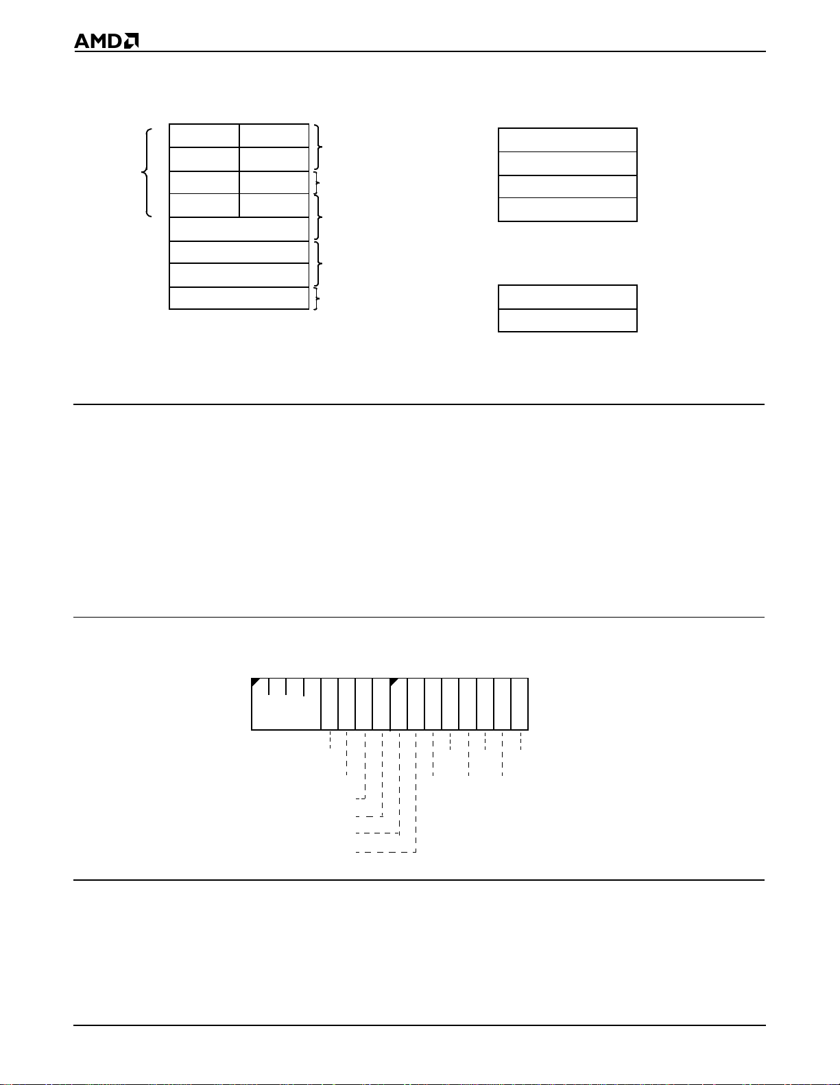
Figure 1-1 Register Set
16-Bit
Register
Name
Byte
Addressable
(8-Bit
Register
Names
Shown)
7 0 7 0
AX
DX
CX
BX
BP
SI
DI
SP
AH
DH
CH
BH
base pointer
source index
destination index
15 0
General
Registers
AL
DL
CL
BL
Special
Register
Functions
Multiply/Divide
I/O Instructions
Loop/Shift/Repeat/Count
Base Registers
Index Registers
Stack Pointer
Register
1.1.1 Processor Status Flags Register
The 16-bit processor stat us flags regi ster (see Figure 1- 2) records specific characte ristic s
of the result of logical and arithmeti c instructions (bits 0, 2, 4 , 6, 7, and 11) and controls the
operation of the microcontroller within a given operating mode (bits 8, 9, and 10).
16-Bit
Name
CS
DS
SS
ES
FLAGS
15 0
Segment Registers
15 0
IP
Status and Control
Registers
Code Segment
Data Segment
Stack Segment
Extra Segment
Processor Status Flags
Instruction Pointer
After an instruction is executed, the value of a flag may be set (to 1), cleared/reset (to 0),
unchanged, or undefined. The term
undefined
of the instruc tion is not preserved, and the value of the flag after the instruction is executed canno t
be predicted. The docu mentat ion for ea ch i nstru ctio n ind ica tes ho w each flag bit i s aff ect ed by
that instruction.
Figure 1-2 Processor Status Flags Register (FLAG S)
15
Reserved
OF
DF
IF
TF
SF
ZF
70
AF
Res
Bits 15–12—Reserved.
means that the fla g value prior to the execu tion
PF
CF
Res
Res
1-2
Bit 11: Overflow Flag (OF)—Set if the signed result cannot be expressed within the number
of bits in the destination operand, cleared o ther wise.
Programming

Bit 10: Direction Flag (DF)—Causes string instructions to auto decrement the appropriate
index registers when set. Clearing DF causes auto-increment. See the CLD and STD
instructions, respectively, for how to clear and set the Direction Flag.
Bit 9: Interrupt-Enable Flag (IF)—When set, enables maskable interrupts to cause the
CPU to transfer control to a locati on sp ecifi ed by an i nter rupt v ector. See t he CLI and STI
instructions, respectively, for how to clear and set the Interrupt-Enable Flag.
Bit 8: Trace Flag (TF)—When set, a trace interrupt occurs after instructions execute. TF
is cleared by the t race interr upt after t he processor st atus flags are pushed onto t he stack.
The trace service routine can continue tracing by popping the flags back with an IRET
instruction.
Bit 7: Sign Flag (SF)—Set equal to high-order bit of result (set to 0 if 0 or positive, 1 if
negative).
Bit 6: Zero Flag (ZF)—Set if result is 0; clear ed otherwise.
Bit 5: Reserved
Bit 4: Auxiliary Carry (AF)—Set on carry f rom or borrow to the low-or der 4 bits of the AL
general-purpose register; cleared otherwise.
Bit 3: Reserved
Bit 2: Parity Flag (PF)—Set if low-order 8 bi ts of resul t contain an ev en number of 1 bits;
cleared otherwise.
Bit 1: Reserved
Bit 0: Carry Flag (CF)—Set on high- order bit c arry or borr ow; cleared ot herwise . See the
CLC, CMC, and STC instructions, respectively, f or how to clear, toggl e, and set the Carry
Flag. You can use CF to indicate the outcome of a procedure, such as when searching a
string for a charact er. For inst ance, if t he character i s found, you c an use STC to set CF to
1; if the character is not found, you can use CLC to clear CF to 0. Then, subsequent
instructions that do not aff ect CF c an use its val ue to det ermine t he a ppropri ate course of
action.
1.2 INSTRUCTION SET
Each member of the Am186 and Am188 f amily of microcontrollers shares the standa rd 186
instruction set. An instruction can reference from zero to several operands. An operand
can reside in a register , in the inst ruction itself, or in memory. Specif ic operand addressi ng
modes are discussed on page 1-7.
Chapter 2
instructions.
in both functional and alphabetical order.
provides an overview of the instruction set, describing the format of the
Chapter 3
lists all the instruc tions for the Am186 and Am188 microcontr ollers
Chapter 4
details each ins tru c tion.
1.3 MEMORY ORGANIZATION AND ADDRESS GENERATION
The Am186 and Am188 microcontrollers organize memory in sets of segments. Memory
is addressed using a two-component address that consists of a 16-bit segment value and
a 16-bit offset. Each segment is a linear contiguous sequence of 64K (2
memory in the processor’s address space. The offset is the number of bytes from the
beginning of the segment (the segment address) to t he data or instruction which is being
accessed.
16
) 8-bit bytes of
The processor forms the physical address of the target location by taking the segment
address, shifting it to the left 4 bits (multi plying by 16), and adding this to the 16-b it offset.
Programming
1-3
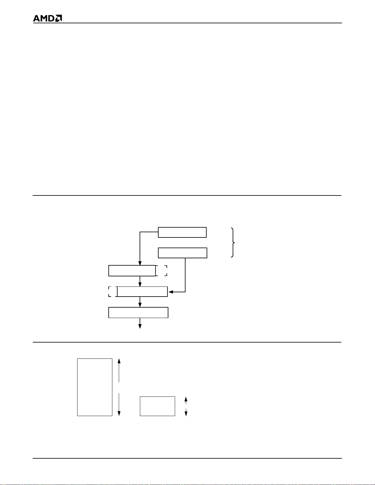
The result is a 20-bit address of the target data or instruction. This al low s f or a 1- Mby te phys ica l
address size.
For example, if the segment register is loaded with 12A4h and the offset i s 0022h, the
resultant address is 12A62h (see Figure 1-3). To find the result:
1. The segment register contains 12A4h.
2. The segment register is shifted 4 places and is now 12A40h.
3. The offset is 0022h.
4. The shifted segment address (12A40h) is added to the offset (00022h) to get 12A62h.
5. This address is placed on the address bus pins of the controller.
All instructions that addr ess operands in memory must s pecify (implicitly or expl icitly) a 16-
bit segment value and a 16-bi t offset value. The 1 6-bit segmen t values are contain ed in one
of four internal segment registers (CS, DS, ES, and SS). See "Addressing Modes” on page
1-7 for more information on calculating the segment and offset values. See "Segments" on
page 1-5 for more information on the CS, DS, ES, and SS registers.
In addition to memory spac e, all Am186 an d Am188 microcontrol lers provi de 64K of I/O space
(see Figure 1-4). The I/O space is described on page 1-5.
Figure 1-3 Physical-Address Generation
Shift Left
4 Bits
1 2 A 4 0
19 0
0 0 0 2 2
15 0
1 2 A 6 2
19 0
To Memory
Figure 1-4 Memory and i/O Space
Memory
Space
1M
1 2 A 4
15 0
0 0 2 2
15 0
Physical Address
Segment
Base
Logical Address
Offset
1-4
I/O
Space
64K
Programming
1.4 I/O SPACE
The I/O space consists of 64K 8-bit or 32K 16-bit port s. The IN and OUT instructions address
the I/O space with either an 8-bit port addr ess specified in the instruction, or a 16-bit port
address in the DX register. 8-bit port addresses are zero-extended so that A15–A8 are
Low. I/O port addresses 00F8h through 00FFh are reserved. The Am186 and Am188
microcontrollers provide spe cific instructions for addressing I/O spac e.
1.5 SEGMENTS
The Am186 and Am188 microcontrollers use four segment registers:
1. Data Segment (DS): The processor assumes that all accesses to the program’s
variables are from the 64K space pointed to by the DS register. The data segment holds
data, operands, etc.
2. Code Segment (CS): This 64K space is the def ault location for all instructions. All code
must be executed from the code segment.
3. Stack Segment (SS): The processor uses the SS register to perform operations that
involve the stack, such as pushes and pops. The st ack segment i s used for t emporar y
space.
4. Extra Segment (ES): Usually this segment is used for l a rge string operations and for
large data structures. Certain str ing i n structions assume the extra segment as the
segment portion of the address. The extra segment is also used (by using segment
override) as a spare data segment.
When a segment register is not specified for a da ta movement instruction, it’s assumed to
be a data segment. An instruction prefix can be used to override the segment regist er (see
"Segment Override Prefix" on page 2-2).For speed and compact instruction encoding, the
segment register used for phy sical-address generation is impli ed by the addre ssing mode
used (see Table 1-1).
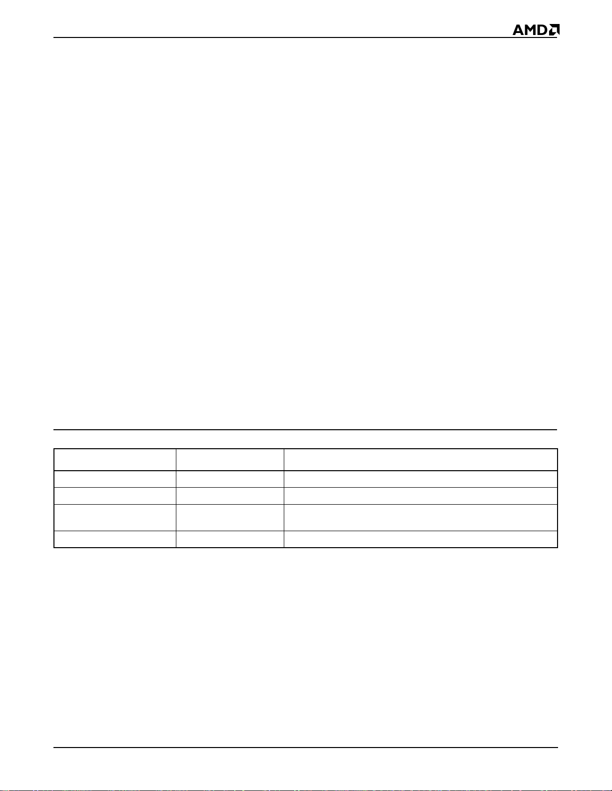
Table 1-1 Segment Register Selection Rules
Memory Reference Ne eded Segment Register Used Implicit Segment Selection Rule
Local Data Data (DS) All data references
Instructions Code (CS) Instructions (including immedi ate data)
Stack Stack (SS) All stack pushes and pops
Any memory references that use the BP registe r
External Data (Global) Extra (ES) All string instruction references that use th e DI register as an index
1.6 DATA TYPES
The Am186 and Am188 microcontrollers directly support the following data types:
n Integer—A signed binary numeric value contai ned in an 8-bit byte or a 16-bit word. All
operations assume a two’s complement representation.
n Ordinal—An unsigned binary numeric va lue contained in an 8-bit byte or a 16-bit word.
n Double Word—A signed binary numeric value contained in two sequential 16-bit
addresses, or in a DX::AX register pair.
n Quad Word—A signed binary numeric value contained in four sequential 16-bit
addresses.
n BCD—An unpacked byte representation of the decimal digits 0–9.
Programming
1-5
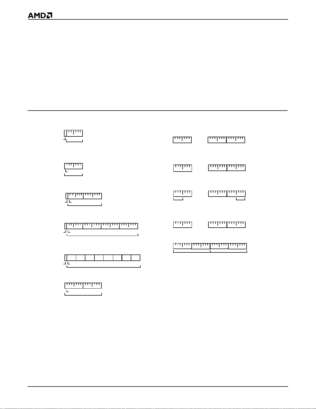
n ASCII—A byte representation of alp hanumeric and c ontrol charact ers using the ASCII
standard of character representation.
n Packed BCD—A packed byte representation of two decimal digits (0–9). One digit is
stored in each nibble (4 bits) of the byte.
n String—A contiguous sequence of by tes or words. A string can contain fr om 1 byte up
to 64 Kbyte.
n Pointer—A 16-bit or 32-bit quantit y, composed of a 16-bit of fset component or a 16-bit
segment base component plus a 16-bit offset component.
In general, individual data elements must fit within defined segment limits. Figure 1-5
graphically represents the data types supported by the Am186 and Am188 microcont rollers.
Figure 1-5 Supported Data Types
Signed
Byte
Sign Bit
Unsigned
Byte
Signed
Word
Sign Bit
Signed
Double
Word
Sign Bit
Signed
Quad
Word
Sign Bit
Unsigned
Word
7 0
Magnitude
7 0
MSB
Magnitude
+1 0
1514 8 7 0
MSB
Magnitude
+3 +2 +1 0
31 1615 0
MSB
Magnitude
63 48 47 32 31 16 15 0
+3 +2 +1+6 +5 +4 +0+7
MSB
Magnitude
+1 0
015
MSB
Magnitude
Binary
Coded
Decimal
(BCD)
ASCII
Packed
BCD
String
Pointer
+N
7 0
+1
7 0 7 0
. . .
BCD
Digit N
+N
7 0 7 0 7 0
BCD
Digit 1
+1 0
BCD
Digit 0
. . .
ASCII
Character
7 0
N
+N +1 0
ASCII
Character
7 0 7 0
Character
1
. . .
Most
Significant Digit
+N
7
0
Significant Digit
+1 0
7 0
7 0
. . .
Byte/WordN
+3 +2 +1 0
Segment Base
Byte/Word1 Byte/Word0
Offset
0
ASCII
0
Least
1-6
Programming
1.7 ADDRESSING MODES
The Am186 and Am188 microcontrollers use eight categories of addressing modes to
specify operands. Two addressing modes are provided for instructions that operate on
register or immediate operands; six modes are provided to specify the location of an
operand in a memory segment.
Register and Immediate Operands
1. Register Operand Mode—The operand is located in one of the 8- or 16-bit registers.
2. Immediate Operand Mode—The operand is included in the instruction.
Memory Operands
A memory-operand address consists of two 16-bit components: a segment value and an
offset. The segment value is supplied by a 16-bit segme nt register either i mplicitly chosen
by the addressing mode (described below) or expli citly chosen by a segment override prefix
(see "Segment Override Prefix" on page 2-2). The offset, also called the effective address,
is calculated by summing any combination of the following three address elements:
n Displacement—an 8-bit or 16- bit i mmediat e valu e cont aine d in th e ins truct ion
n Base—contents of either the BX or BP base regi ster s
n Index—contents of either th e SI or DI index registe rs
Any carry from the 16-bit addition is ignored. Eight-bit displacements ar e sign-extended to
16-bit values.
Combinations of the above three address elements define the following six memory
addressing modes (see Table 1-2 for examples).
1. Direct Mode—The operand off set i s contain ed in the ins tructi on as an 8 - or 16- bit
displacement element.
2. Register Indirect Mode—The op eran d offset is in o ne of the BP, BX, DI, or SI re giste rs.
3. Based Mode—The operand offset is the sum of an 8- or 16-bit displacement and the contents
of a base regist er (BP or BX).
4. Indexed Mode—The operand offset is th e sum of an 8 - or 16- bit dis placeme nt an d the
contents of an index register (DI or SI).
5. Based Indexed Mode—The operand o ffset is the su m of the co nten ts of a b ase regis ter
(BP or BX) and an index register (DI or SI).
6. Based Indexed Mode with Displacement—The op erand of fset i s the sum of a base
register’s conten ts, an index regis ter’ s conte nts, an d an 8- bit or 16-b it disp lac ement .
Table 1-2 Memory Addressing Mode Examples
Addressing Mode Example
Direct mov ax, ds:4
Register Indirect mov ax, [si]
Based mov ax, [bx]4
Indexed mov ax, [si]4
Based Indexed mov ax, [si][bx]
Based Indexed with Displacement mov ax, [si][bx]4
Programming
1-7

1-8
Programming

CHAPTER
INSTRUCTION SET OVERVIEW
2
2.1 OVERVIEW
The instruction set used by the Am186 and Am188 family of microcontrollers is identical to
the original 8086 and 8088 instruction set, with the addition of seven instructions (BOUND,
ENTER, INS, LEAVE, OUTS, POPA, and PUSHA), and the enhancement of nine
instructions (immediate operands were added to IMUL, PUSH, RCL, RCR, ROL, ROR,
SAL/SHL, SAR, and SHR). In addition, three valid instructions are not suppo rt ed with the
necessary processor pinout (ESC, LOCK and WAIT). All of these instr uctions are mar ked
as such in their description.
2.2 INSTRUCTION FORMAT
When assembling code, an assembler replaces each instructi on statement with its
machine-language equivalent. In mach ine langu age, all i nstructi ons conform to one basic
format. However, the length of an instruction in machi ne language varies depending on the
operands used in the instruction and the operation that the instruction performs.
An instruction can reference from zero to several operands. An operand can reside in a
register, in the instruction itself, or in memory.
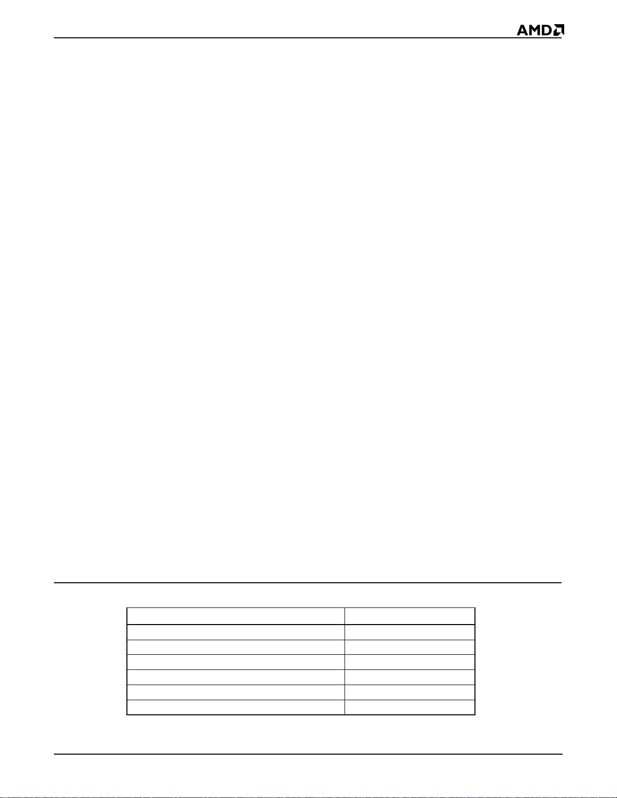
The Am186 and Am188 microcontrolle rs use the foll owing instruction f ormat. The shortest
instructions consist of only a single opcode byte.
Instruction Prefixes
Segment Override Prefix
Opcode
Operand Address
Displacement
Immediate
2.2.1 Instruction Pref ix es
The REP, REPE, REPZ, REPNE and REPNZ prefixes can be used to repeatedly execute
a single string instruction.
The LOCK prefix may be combined with the instruction and segment over ride prefixes, and
causes the processor to assert its bus LOCK signal while the instruction that follows
executes.
Instruction Set Overview
2-1
2.2.2 Segment Override Prefix
To override the default segment register, place the following byte in fro nt of the instruction,
where RR determines which register is used. Only one segment override prefix can be
used per instruction.
Segment Override
Prefix
0 0 1 1 1 0
2.2.3 Opcode
This specifies the machine- language opcode for an in struction. The format for the opcodes
is described on page 2-5. Although most instructions use only one opcode byte, the AAD
(D5 0A hex) and AAM (D4 0A hex) instructions use two opcodes.
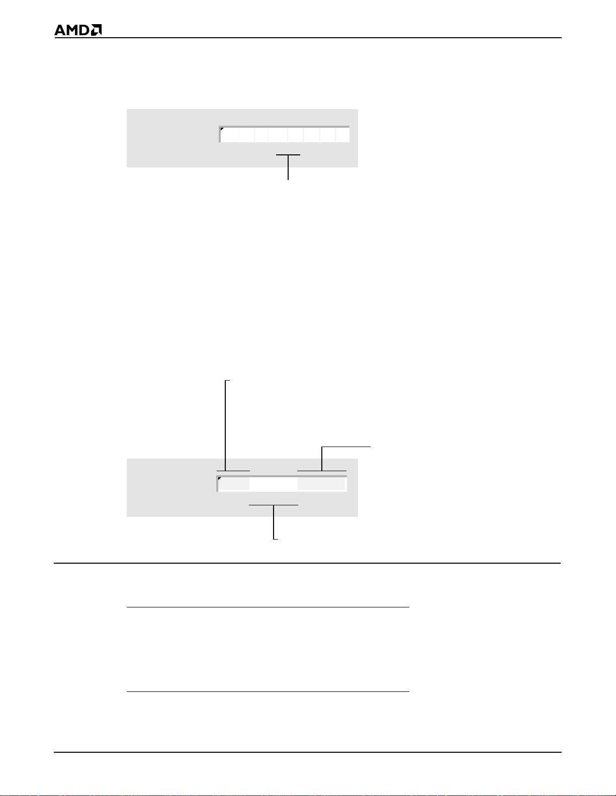
2.2.4 Operand Address
The following illustration shows the structure of the operand address byte. The operand
address byte controls the addressing for an instruction.
Along with
interpreted as a register or the address of a memory operand. For a memory
operand, the Modifi er field also indicates whether t he operand is addressed direc tly
or indirectly. For indi rectly addressed memory operands, the Modifier field specifies
the number of bytes of d isplacem ent that ap pear in the ins truction. Se e Table 2-1
for
R R
00 = ES Register
01 = CS Register
10 = SS Register
11 = DS Register
r/m
mod
values.
01234567
, the Modifier field d etermines w hether the Regi ster/Memory field is
Operand Address mod aux r/m
Table 2-1 mod field
mod Description
11
00 DISP = 0, disp-low and disp-high are absent
01 DISP = disp-low sign-extended to 16-bits, disp-high
10 DISP = disp-high: disp-low
r/m
is treated as a
is absent
mod
Along with
specifies a genera l register or the address of a
memory operand. See Table 2-3 for
01234567
The Auxiliary field specifies an opcode extension or a register
that is used as a second operand. See Table 2-2 for
reg
field
, the Register/Memory field
aux
r/m
values.
values
2-2
Instruction Set Overview

Table 2-2 aux field
aux If mod=11 and w=0 If mod=11 and w=1
000 AL AX
001 CL CX
010 DL DX
011 BL BX
100 AH SP
101 CH BP
110 DH SI
111 BH DI
* – When mod≠11, depends on instruction
Table 2-3 r/m field
r/m Description
000 EA* = (BX)+(SI)+DISP
001 EA = (BX)+(DI)+DISP
010 EA = (BP)+(SI)+DISP
011 EA = (BP)+(DI)+DISP
100 EA = (SI)+DISP
101 EA = (DI)+DISP
110 EA = (BP)+DISP (except if mod=00, then EA = disp-high:disp:low)
111 EA = (BX)+DISP
* – EA is the Effective Address
2.2.5 Displacement
The displacement is an 8- or 16- bit immediate value to be adde d to the offset portion of the
address.
2.2.6 Immediate
The immediate bytes contain up to 16 bits of immediate data.
2.3 NOTATION
This parameter Indicates that
: The component on the left is the segment for a component located in
memory. The component on the right is the offset.
:: The component on the left is concatenated with the component on the right.
Instruction Set Overview
2-3

2.4 USING THIS MANUAL
Each instruction is detailed in Chapter 4. The following sections explain the format used
when describing each instruction.
2.4.1 Mnemonics and Names
The primary assembly-language mnemoni c and its name appear at the top of the first page
for an instruction (see Figure 2-1) . Some inst ructions have additional mnemonics that
perform the same operation. These synonyms are listed below the primary mnemonic.
Figure 2-1 Instruction Mnemon ic and Name Sample
MUL Multiply Unsigned Numbers
2.4.2 Form s of th e In s truction
Many instructions have more than one form. The forms for each instruc tion are lis ted in a
table just below the mnemonics (see Figure 2-2).
Figure 2-2 Instruction For ms Tab l e Sa m ple
Form Opcode Description
MUL
MUL
r/m8
r/m16
Form
F6
F7
/4
/4
AX=(r/m byte)•AL 26–28/32–34 26–28/32–34
DX::AX=(r/m word)•AX 35–37/41–43 35–37/45–47
The Form column specifies the syntax for t he d if ferent forms of an instruction. Each form
includes an instruction mnemonic and zero or more oper ands. Items in italics are
placeholders for operand s that must be provided. A placeholder indi cates the size and type
of operand that is allowed.
This operand Is a placeholder for
imm8
imm16
m
m8
m16
m16&16
m16:16
moffs8
moffs16
ptr16:16
r8
r16
r/m8
r/m16
rel8
rel16
sreg
An immediate byte: a signed number between –128 and 127
An immediate word: a signed number betwe en –327 68 and 327 67
An operand in memory
A byte string in memory pointed to by DS:SI or ES:DI
A word string in memory pointed to by DS:SI or ES:DI
A pair of words in memory
A doubleword in memory that contains a full address (segment:offset)
A byte in memory that contains a signed, relative offset displacement
A word in memory that contains a signed, relative offset displacement
A full address (segment:offset)
A general byte register: AL, BL, CL, DL, AH, BH, CH, or DH
A general word register: AX, BX, CX, DX, BP, SP, DI, or SI
A general byte register or a byte in memory
A general word register or a word in memory
A signed, relative offset displacement between –128 and 127
A signed, relative offset displac em ent betw een –32768 and 32767
A segment register
Clocks
Am186 Am188
2-4
Instruction Set Overview

Opcode
The Opcode column specifies the machi ne-language opcodes for th e different forms of an
instruction. (For instruction prefixes, this column also includes the prefi x.) Each opcode
includes one or more numbers in hexadeci mal format, and zero or more parameters, which
are shown in italics. A parameter prov ides informat ion about the cont ents of t he Operand
Address byte for that particular form of the inst ruction.
This parameter Indicates that
/0–/
/
r
/
sr
cb
cd
cw
ib
iw
rb
rw
7
/0 The aux field is 0.
/1 The aux field is 1.
/2 The aux field is 2.
/3 The aux field is 3.
/4 The aux field is 4.
/5 The aux field is 5.
/6 The aux field is 6.
/7 The aux field is 7.
The Auxiliary (aux) Field in the Operand Address byte specifies an
extension (from 0 to 7) to the opcode instead of a register. So for example,
the opcode for adding (ADD) an immediate byte to a general byte register
ib
or a byte in memory is "80 /0
"mod 000 r/m", where mod and r/m are as defined in "Operand Address"
on page 2-2.
The Auxiliary (aux) field in the Operand Address byte specifies a register
instead of an opcode extension. If the Opcode byte specifies a byte register,
the registers are assigned as follows: AL=0, CL=1, DL=2, BL=3, AH=4,
CH=5, DH=6, and BH=7. If the Opcode byte specifies a word register, the
registers are assigned as follows: AX=0, CX=1, DX=2, BX=3, SP=4, BP=5,
SI=6, and DI=7.
The Auxiliary (aux) field in the Operand Address byte specifies a segment
register as follows: ES=0, CS=1, SS=2, and DS=3.
The byte following the Opcode byte specifies an offset.
The doubleword following the Opcode byte specifies an offset and, in some
cases, a segment.
The word following the Opcode byte specifies an offset and, in some cases,
a segment.
The parameter is an immediate byte. The Opcode byte determines whether
it is interpreted as a signed or unsigned number.
The parameter is an immediate word. The Opcode byte determines whether
it is interpreted as a signed or unsigned number.
The byte register operand is specified in the Opcode byte. To determine
the Opcode byte for a particular register, add the hexadecimal value on the
left of the plus sign to the value of
AL=0, CL=1, DL=2, BL= 3, AH=4, CH=5, DH=6, and BH=7. So for example,
the opcode for moving an immediate byte to a register (MOV) is "B0+
So B0–B7 are valid opcodes, and B0 is "MOV AL,
The word register operand is specified in the Opcode byte. To determine
the Opcode byte for a particular register, add the hexadecimal value on the
left of the plus sign to the value of
AX=0, CX=1, DX=2, BX=3, SP=4, BP=5, SI=6, DI=7.
". So the second byte of the opcode is
rb
for that register, as follows:
imm8
".
rw
for that register, as follows:
rb
".
Instruction Set Overview
2-5

Description
The Description column contains a brief synopsis of each form of the instruction.
Clocks
The Clocks columns (one for the Am186 and one for the Am188 microcontrollers ) specify
the number of clock cycles required for the different forms of an instruction.
This parameter Indicates that
/
,
n
2.4.3 What It Does
This section contains a brief description of the operation the instruction performs.
2.4.4 Syntax
This section shows the syntax for the instruction. Instructions with more than one mnemonic
show the syntax for each mnemonic.
The number of clocks required for a register operand is different than the
number required for an operand located in memory. The number to the
left corresponds with a register operand; the number to the right
corresponds with an operand located in memory.
The number of clocks depends on the result of the condition tested. The
number to the left corresponds with a True or Pass result, and the number
to the right corresponds with a False or Fail result.
The number of clocks depends on the number of times the instruction is
n
repeated.
is the number of repetitions.
2.4.5 Description
This section contains a more in-depth descript ion of the instruction.
2-6
Instruction Set Overview

2.4.6 Operation It Performs
This section uses a combination of C-language and assembler syntax t o describe the
operation of the instruction in detail. In some cases, pseudo-code functions are used to
simplify the code. These functions and the actions they perform are as follows:
Pseudo-Code Function Action
cat(
componenta,componentb
execute(
interrupt(
interruptRequest() Return True if the microcontroller receives a maskable
leastSignificantBit(
mostSignificantBit(
nextMostSignificantBit(
nmiRequest() Return True if the microcontroller receives a nonmaskable
operands() Return the number of operands present in the instruction.
pop() Read a word from the top of the stack, increment SP, and
pow(n,
push(
resetRequest() Return True if a device resets the microcontroller by asserting
serviceInterrupts() Service any pending interrupts.
size(
stopExecuting() Suspend execution of current instruction sequence.
instruction
type
) Issue an interrupt request to the microcontroller.
component
component
component
) Execute the instruction.
component
component
) Raise component to the nth power.
) Decrement SP and copy the component to the top of the
) Return the size of the component in bits.
) Component A is concatenated with component B.
component
interrupt request.
) Return the least significant bit of the component.
) Return the most significant bit of the component.
) Return the next most significant bit of the component.
interrupt request.
return the value.
stack.
the RES
signal.
2.4.7 Flag Settings After In struction
This section identifies the flags that are set, cleared, modified according to the result,
unchanged, or left undefined by the instruction. Each instruction has the graphic below,
and shows values for the flag bits after the instruction is performed. A "?" in the bit field
indicates the value is undefined; a "–" i ndicates the bit value is unchanged. See "Processor
Status Flags Register" on page 1-2 for more information on the flags.
Processor Status
Flags Register
? = undefined; – = unchanged
reserved
15 14 13 12 11 10 9 8 7 6 5 4 3 2 1 0
OF DF IF TF SF ZF AF PF CF
2.4.8 Examples
This section contains one or more examples t hat illustrate possible use s for the instruction.
The beginning of each example is marked with a printout icon ; a summary of the example’s
function appears next to it. The exampl e code foll ows the summary. Not e that some of the
examples use assembler directives: CONST (def ine constant d ata), DB (defi ne byte), DD
(define double), DW (define word), EQU (equate), LENGTH (length of array), PROC (begin
procedure), SEGMENT (define segment), SIZE (return integer size) and TYPE (return
integer type).
res res res
? = unknown; – = unchanged
Instruction Set Overview
2-7

2.4.9 Tips
This section contains hints and i deas about some of the way s in which the i nstructi on can
be used.
Tips are marked with this icon.
2.4.10 Related Instructions
This section lists other instructions rel ated to the described instruction.
2-8
Instruction Set Overview

CHAPTER
INSTRUCTION SET LISTING
3
This chapter lists all the instructions for the Am186 and Am188 family of microcontrol lers.
The instructions are first grouped by type (see page 3-1) and then listed in alphabetical
order (see page 3-11)
3.1 INSTRUCTION SET BY TYPE
The instructions can be classified into groups according to the type of operation they
perform. Instructions that are used for more than one purpose are listed under each category
to which they belong. The functional groups are:
n "Address Calculation and Translation" on page 3-1
n "Binary Arithmetic" on page 3-2
n "Block-Structured Language" on page 3-3
n "Comparison" on page 3-3
n "Control Transfer" on page 3-3
n "Data Movement" on page 3-5
n "Decimal Arithmetic" on page 3-6
n "Flag" on page 3-7
n "Input/Output" on page 3-8
n "Logical Operation" on page 3-8
n "Processor Control" on page 3-9
n "String" on page 3-9
3.1.1 Address Calculation and Translat ion
Address Calculation Instructions
Mnemonic Name See Page
LDS Load DS with Segment and Register with Offset 4-131
LEA Load Effective Address 4-133
LES Load ES with Segment and Register with Offset 4-138
Address Translation Instructions
Mnemonic Name See Page
XLAT Translate Table Index to Component 4-248
XLATB Translate Table Index to Byte (
Synonym for
XLAT) 4-248
Instruction Set Listing
3-1

3.1.2 Binary Arithmetic
The microcontroller supports binary arit hmetic using numbers represented in the two’s
complement system. The t wo’s complement system uses the high bit of an integer (a signed
number) to determine the sign of the number. Unsigned numbers have no sign bit.
Binary Addition Instructions
Mnemonic Name See Page
ADC Add Numbers with Carry 4-10
ADD Add Numbers 4-14
INC Increment Number by One 4-69
Binary Subtraction Instructions
Mnemonic Name See Page
DEC Decrement Number by One 4-48
SBB Subtract Numbers with Borrow 4-216
SUB Subtract Numbers 4-240
Binary Multiplication Instructions
Mnemonic Name See Page
IMUL Multiply Integers 4-63
MUL Multiply Unsigned Numbers 4-160
SAL Shift Arithmetic Left 4-211
SHL Shift Left (
Binary Divis ion Instruct ions
Mnemonic Name See Page
DIV Divide Unsigned Numbers 4-50
IDIV Divide Integers 4-60
SAR Shift Arithmetic Right 4-214
SHR Shift Right 4-225
Binary Conversion Instructions
Mnemonic Name See Page
CBW Convert Byte Integer to Word 4-24
CWD Convert Word Integer to Doubleword 4-40
NEG Two’s Complement Negation 4-163
Synonym for
SAL) 4-211
3-2
Instruction Set Listing

3.1.3 Block-Structu red Language
Block-Structured Language Instructions
Mnemonic Name See Page
ENTER Enter High-Level Procedure 4-53
LEAVE Leave High-Level Procedure 4-135
3.1.4 Comparison
General Comparison Instructions
Mnemonic Name See Page
CMP Compare Comp one nts 4-34
TEST Logical Compare 4-243
String Compari s on Instructions
Mnemonic Name See Page
CMPS Compare String Components 4-36
CMPSB Compare String Bytes (
CMPSW Compare String Words (
SCAS Scan String for Component 4-219
SCASB Scan String for Byte (
SCASW Scan String for Word (
Synonym for
Synonym for
Synonym for
Synonym for
CMPS) 4-36
CMPS) 4-36
SCAS) 4-219
SCAS) 4-219
3.1.5 Control Transfer
Conditional Jump Instructions to Use after Integer Comparisons
Mnemonic Name See Page
JG Jump If Greater 4-91
JGE Jump If Greater or Equal 4-93
JL Jump If Less 4-95
JLE Jump If Less or Equal 4-97
JNG Jump If Not Greater (
JNGE Jump If Not Greater or Equal (
JNL Jump If Not Less (
JNLE Jump If Not Less or Equal (
Synonym for
Synonym for
Synonym for
JLE) 4-97
Synonym for
JGE) 4-93
JL) 4-95
JG) 4-91
Instruction Set Listing
3-3

Conditional Jump Instructions to Use after Unsigned Number Comparisons
Mnemonic Name See Page
JA Jump If Above 4-78
JAE Jump If Above or Equal 4-80
JB Jump If Below 4-82
JBE Jump If Below or Equal 4-84
JNA Jump If Not Above (
JNAE Jump If Not Above or Equal (
JNB Jump If Not Below (
JNBE Jump If Not Below or Equal (
Conditional Jump Instructions That Test for Equality
Mnemonic Name See Page
JE Jump If Equal 4-89
JNE Jump If Not Equal 4-107
Conditional Jump Instructions That Test Flags
Mnemonic Name See Page
JC Jump If Carry (
JNC Jump If Not Carry (
JNO Jump If Not Overflow 4-113
JNP Jump If Not Parity (
JNS Jump If Not Sign 4-116
JNZ Jump If Not Zero (
JO Jump If Overflow 4-119
JP Jump If Parity (
JPE Jump If Parity Even 4-122
JPO Jump If Parity Odd 4-124
JS Jump If Sign 4-126
JZ Jump If Zero (
Synonym for
Synonym for
Synonym for
Synonym for
Synonym for
Synonym for
Synonym for
Synonym for
JBE) 4-84
Synonym for
JAE) 4-80
Synonym for
JB) 4-82
JAE) 4-80
JPO) 4-124
JNE) 4-107
JPE) 4-121
JE) 4-89
JB) 4-82
JA) 4- 78
3-4
Conditional Interrupt Instructions
Mnemonic Name See Page
BOUND Check Array Index Against Bounds 4-19
IDIV Divide Integers 4-60
INTO Generate Interrupt If Overflow (
Instruction Set Listing
Conditional form of
INT) 4-73

Conditional Loop Instructions
Mnemonic Name See Page
JCXZ Jump If CX Register Is Zero 4-87
LOOP Loop While CX Register is Not Zero 4-146
LOOPE Loop If Equal 4-148
LOOPNE Loop If Not Equal 4-150
LOOPNZ Loop If Not Zero (
LOOPZ Loop If Zero (
Unconditional Transfer Instructions
Mnemonic Name See Page
CALL Call Procedure 4-21
INT Generate Interrupt 4-73
IRET Interrupt Return 4-76
JMP Jump Unconditionally 4-99
RET Return from Procedure 4-202
3.1.6 Data Movement
Synonym for
Synonym for
LOOPNE) 4-150
LOOPE) 4-148
General Movement Instructi ons
Mnemonic Name See Page
MOV Move Component 4-153
XCHG Exchange Components 4-246
String Movement Instructions
Mnemonic Name See Page
LODS Load String Component 4-141
LODSB Load String Byte (
LODSW Load String Word (
MOVS Move String Component 4-156
MOVSB Move String Byte (
MOVSW Move String Word (
STOS Store String Component 4-237
STOSB Store String Byte (
STOSW Store String Word (
Synonym for
Synonym for
Synonym for
Synonym for
Synonym for
Synonym for
LODS) 4-141
LODS) 4-141
MOVS) 4- 15 6
MOVS) 4-156
STOS) 4-237
STOS) 4-237
Instruction Set Listing
3-5

Stack Movement Inst r uctions
Mnemonic Name See Page
POP Pop Component from Stack 4-175
POPA Pop All 16-Bit General Registers from Stack 4-178
POPF Pop Flags from Stack 4-180
PUSH Push Component onto Stack 4-181
PUSHA Push All 16-Bit General Registers onto Stack 4-184
PUSHF Push Flags onto Stack 4-186
General I/O Movement Instructions
Mnemonic Name See Page
IN Input Component from Port 4-67
OUT Output Component to Port 4-171
String I/O Movement Instructions
Mnemonic Name See Page
INS Input String Component from Port 4-71
INSB Input String Byte from Port (
INSW Input String Word from Port (
OUTS Output String Component to Port 4-173
OUTSB Output String Byte to Port (
OUTSW Output String Word to Port (
Synonym for
Synonym for
Synonym for
Synonym for
INS) 4-71
INS) 4-71
OUTS) 4-17 3
OUTS) 4-173
Flag Movemen t Instructions
Mnemonic Name See Page
LAHF Load AH with Flags 4-129
SAHF Store AH in Flags 4-209
3.1.7 Decimal Arithmetic
In addition to binary arithmetic, the microcontroller supports arithmetic using numbers
represented in the binary-coded decimal (BCD) system. The BCD system uses four bits to
represent a single decimal digit. When two decimal digits are stored in a byte, the number
is called a
packed
number is called an
To perform decimal arithmetic, the microcon troller uses a subset of the binary arithmetic
instructions and a special set of instructions that convert unsigned binary numbers to
decimal.
Arithmetic Instructions That Are Used with Decimal Numbers
Mnemonic Name See Page
ADD Add Numbers 4-14
DIV Divide Unsigned Numbers 4-50
MUL Multiply Unsigned Numbers 4-160
SUB Subtract Numbers 4-240
decimal number. When only one decimal digit is stored in a byte, the
unpacked
decimal number.
3-6
Instruction Set Listing

Unpacked-Decimal Adjustment Instructions
Mnemonic Name See Page
AAA ASCII Adjust AL After Addition 4-2
AAD ASCII Adjust AX Before Division 4-4
AAM ASCII Adjust AL After Multiplication 4-6
AAS ASCII Adjust AL After Subtraction 4-8
Packed-Decimal Adjustment Instructions
Mnemonic Name See Page
DAA Decimal Adjust AL After Addition 4-42
DAS Decimal Adjust AL After Subtraction 4-45
Consider using decimal arithmetic instead of binary arithmetic under the following
circumstances:
n When the numbers you are using represent only decimal quantities.
Manipulating numbers in binary and converting them back and fort h between binary and
decimal can introduce rounding errors.
n When you need to read or write many ASCII numbers.
Converting a number between ASCII and decimal is simpler than converting it between
ASCII and binary.
3.1.8 Flag
Single-Flag Instructions
Mnemonic Name See Page
CLC Clear Carry Flag 4-26
CLD Clear Direction Flag 4-29
CLI Clear Interrupt-Enable Flag 4-31
CMC Complement Carry Flag 4-33
RCL Rotate through Carry Left 4-187
RCR Rotate through Carry Right 4-189
STC Set Carry Flag 4-228
STD Set Direction Flag 4-231
STI Set Interrupt-Enable Flag 4-235
Multiple-Flag Instructions
Mnemonic Name See Page
POPF Pop Flags from Stack 4-180
SAHF Store AH in Flags 4-209
Instruction Set Listing
3-7

3.1.9 Input/Output
General I/O Instructions
Mnemonic Name See Page
IN Input Component from Port 4-67
OUT Output Component to Port 4-171
String I/O Instructions
Mnemonic Name See Page
INS Input String Component from Port 4-71
INSB Input String Byte from Port (
INSW Input String Word from Port (
OUTS Output String Component to Port 4-173
OUTSB Output String Byte to Port (
OUTSW Output String Word to Port (
3.1.10 Logical Operation
Boolean Operation Instructions
Mnemonic Name See Page
Synonym for
Synonym for
Synonym for
Synonym for
INS) 4-71
INS) 4-71
OUTS) 4-17 3
OUTS) 4-173
AND Logical AND 4-17
NOT One’s Complement Negation 4-167
OR Logical Inclusive OR 4-169
XOR Logical Exclus ive OR 4-251
Shift Instructions
Mnemonic Name See Page
SAL Shift Arithmetic Left 4-211
SAR Shift Arithmetic Right 4-214
SHL Shift Left (
SHR Shift Right 4-225
Rotate Instructions
Mnemonic Name See Page
RCL Rotate through Carry Left 4-187
RCR Rotate through Carry Right 4-189
ROL Rotate Left 4-205
ROR Rotate Right 4-207
Synonym for
SAL) 4-211
3-8
Instruction Set Listing

3.1.11 Processo r Control
Processor Control Instructions
Mnemonic Name See Page
HLT Halt 4-57
LOCK Lock the Bus 4-140
NOP No Operation 4-165
Coprocessor Interface Instructions
Mnemonic Name See Page
ESC Escape 4-56
WAIT Wait for Coproces sor 4-245
3.1.12 String
A string is a contiguous sequence of components st ored in memory. For example, a string
might be composed of a list of ASCII characters or a table of numbers.
A string instruction operates on a single component in a str ing. To manipulate more than
one component in a string, the string instruct ion
REPZ) can be used to repeatedly execute the same string instruction.
prefixes
(REP/REPE/REPNE/REPNZ/
A string instruction uses an index register as the offset of a component in a string. Most
string instructions operate on only one string, in which case they use either the Source
Index (SI) register or the Destin ation Index (DI) register. St ring instructions that oper ate on
two strings use SI as the offset of a component in one string and DI as the offset of the
corresponding component in the other string.
After executing a string instruction, the microcontroller automatically increments or
decrements SI and DI so that they contain the offsets of the next components in their strings.
The microcontroller determines the amount by which the index registers must be
incremented or decremented based on the size of the components.
The microcontroller can process the components of a string in a forward direction (from
lower addresses to higher addresses), or in a backward direct ion (fr om higher addresses
to lower ones). The microcont roller use s the value of the Direction Fl ag (DF) to determine
whether to increment or decrement SI and DI. If DF is cleared to 0, the microcontroller
increments the index registers; otherwise, it decrements them.
String-Instru ct ion Prefixes
Mnemonic Name See Page
REP Repeat 4-191
REPE Repeat Whil e Equal 4-193
REPNE Repeat While Not Equal 4-197
REPNZ Repeat While Not Zero (
REPZ Repeat While Zero (
Synonym for
Synonym for
REPNE) 4-197
REPE) 4-193
Instruction Set Listing
3-9

String Direction Instructions
Mnemonic Name See Page
CLD Clear Direction Flag 4-29
STD Set Direction Flag 4-231
String Movement Instructions
Mnemonic Name See Page
LODS Load String Component 4-141
LODSB Load String Byte (
LODSW Load String Word (
MOVS Move String Component 4-156
MOVSB Move String Byte (
MOVSW Move String Word (
STOS Store String Component 4-237
STOSB Store String Byte (
STOSW Store String Word (
String Compari s on Instructions
Synonym for
Synonym for
Synonym for
Synonym for
Synonym for
Synonym for
LODS) 4-141
LODS) 4-141
MOVS) 4-156
MOVS) 4-156
STOS) 4-237
STOS) 4-237
Mnemonic Name See Page
CMPS Compare String Components 4-36
CMPSB Compare String Bytes (
CMPSW Compare String Words (
SCAS Scan String for Component 4-219
SCASB Scan String for Byte (
SCASW Scan String for Word (
String I/O Instructions
Mnemonic Name See Page
INS Input String Component from Port 4-71
INSB Input String Byte from Port (
INSW Input String Word from Port (
OUTS Output String Component to Port 4-173
OUTSB Output String Byte to Port (
OUTSW Output String Word to Port (
Synonym for
Synonym for
Synonym for
Synonym for
Synonym for
Synonym for
Synonym for
Synonym for
CMPS) 4-36
CMPS) 4-36
SCAS) 4-219
SCAS) 4-219
INS) 4-71
INS) 4-71
OUTS) 4-17 3
OUTS) 4-173
3-10
Instruction Set Listing

3.2 INSTRUCTION SET IN ALPHABETICAL ORDER
Table 3-1 provides an alphabetical list of the instruction set for the Am186 and Am188
microcontrollers.
Table 3-1 Instruction Set
Mnemonic Instruction Name See Page
AAA ASCII Adjust AL After Addition 4-2
AAD ASCII Adjust AX Before Division 4-4
AAM ASCII Adjust AL After Multiplication 4-6
AAS ASCII Adjust AL After Subtraction 4-8
ADC Add Numbers with Carry 4-10
ADD Add Numbers 4-14
AND Logical AND 4-17
BOUND Check Array Index Against Bounds 4-19
CALL Call Procedure 4-21
CBW Convert Byte Integer to Word 4-24
CLC Clear Carry Flag 4-26
CLD Clear Direction Flag 4-29
CLI Clear Interrupt-Enable Flag 4-31
CMC Complement Carry Flag 4-33
CMP Compare Comp one nts 4-34
CMPS Compare String Components 4-36
CMPSB Compare String Bytes (
CMPSW Compare String Words (
CWD Convert Word Integer to Doubleword 4-40
DAA Decimal Adjust AL After Addition 4-42
DAS Decimal Adjust AL After Subtraction 4-45
DEC Decrement Number by One 4-48
DIV Divide Unsigned Numbers 4-50
ENTER Enter High-Level Procedure 4-53
ESC Escape 4-56
HLT Halt 4-57
IDIV Divide Integers 4-60
IMUL Multiply Integers 4-63
IN Input Component from Port 4-67
INC Increment Number by One 4-69
INS Input String Component from Port 4-71
INSB Input String Byte from Port (
INSW Input String Word from Port (
INT Generate Interrupt 4-73
INTO Generate Interrupt If Overflow (
IRET Interrupt Return 4-76
JA Jump If Above 4-78
JAE Jump If Above or Equal 4-80
JB Jump If Below 4-82
JBE Jump If Below or Equal 4-84
JC Jump If Carry (
JCXZ Jump If CX Register Is Zero 4-87
Synonym for
Synonym for
Synonym for
Synonym for
Synonym for
CMPS) 4-36
CMPS) 4-36
INS) 4-71
INS) 4-71
Conditional form of
JB) 4-82
INT) 4-73
Instruction Set Listing
3-11

Table 3-1 Instruction Set (continued)
Mnemonic Instruction Name See Page
JE Jump If Equal 4-89
JG Jump If Greater 4-91
JGE Jump If Greater or Equal 4-93
JL Jump If Less 4-95
JLE Jump If Less or Equal 4-97
JMP Jump Unconditionally 4-99
JNA Jump If Not Above (
JNAE Jump If Not Above or Equal (
JNB Jump If Not Below (
JNBE Jump If Not Below or Equal (
JNC Jump If Not Carry (
JNE Jump If Not Equal 4-107
JNG Jump If Not Greater (
JNGE Jump If Not Greater or Equal (
JNL Jump If Not Less (
JNLE Jump If Not Less or Equal (
JNO Jump If Not Overflow 4-113
JNP Jump If Not Parity (
JNS Jump If Not Sign 4-116
JNZ Jump If Not Zero (
JO Jump If Overflow 4-119
JP Jump If Parity (
JPE Jump If Parity Even 4-122
JPO Jump If Parity Odd 4-124
JS Jump If Sign 4-126
JZ Jump If Zero (
LAHF Load AH with Flags 4-129
LDS Load DS with Segment and Register with Offset 4-131
LEA Load Effective Address 4-133
LEAVE Leave High-Level Procedure 4-135
LES Load ES with Segment and Register with Offset 4-138
LOCK Lock the Bus 4-140
LODS Load String Component 4-141
LODSB Load String Byte (
LODSW Load String Word (
LOOP Loop While CX Register Is Not Zero 4-146
LOOPE Loop If Equal 4-148
LOOPNE Loop If Not Equal 4-150
LOOPNZ Loop If Not Zero (
LOOPZ Loop If Zero (
MOV Move Component 4-153
MOVS Move String Component 4-156
MOVSB Move String Byte (
MOVSW Move String Word (
MUL Multiply Unsigned Numbers 4-160
NEG Two’s Complement Negation 4-163
NOP No Operation 4-165
Synonym for
Synonym for
Synonym for
Synonym for
Synonym for
Synonym for
Synonym for
Synonym for
Synonym for
Synonym for
Synonym for
Synonym for
JPE) 4-122
JE) 4-89
Synonym for
Synonym for
Synonym for
LOOPE) 4-148
Synonym for
Synonym for
JBE) 4-84
Synonym for
JAE) 4-80
JAE) 4-80
JLE) 4-97
Synonym for
JGE) 4-93
JPO) 4-124
JNE) 4-107
LODS) 4-141
LODS) 4-141
LOOPNE) 4-150
MOVS) 4-156
MOVS) 4-156
JB) 4-82
JA) 4- 78
JL) 4-95
JG) 4-91
3-12
Instruction Set Listing

Table 3-1 Instruction Set (continued)
Mnemonic Instruction Name See Page
NOT One’s Complement Negation 4-167
OR Logical Inclusive OR 4-169
OUT Output Component to Port 4-171
OUTS Output String Component to Port 4-173
OUTSB Output String Byte to Port (
OUTSW Output String Word to Port (
POP Pop Component from Stack 4-175
POPA Pop All 16-Bit General Registers from Stack 4-178
POPF Pop Flags from Stack 4-180
PUSH Push Component onto Stack 4-181
PUSHA Push All 16-Bit General Registers onto Stack 4-184
PUSHF Push Flags onto Stack 4-186
RCL Rotate through Carry Left 4-187
RCR Rotate through Carry Right 4-189
REP Repeat 4-191
REPE Repeat Whil e Equal 4-193
REPNE Repeat While Not Equal 4-197
REPNZ Repeat While Not Zero (
REPZ Repeat While Zero (
RET Return from Procedure 4-202
ROL Rotate Left 4-205
ROR Rotate Right 4-207
SAHF Store AH in Flags 4-209
SAL Shift Arithmetic Left 4-211
SAR Shift Arithmetic Right 4-214
SBB Subtract Numbers with Borrow 4-216
SCAS Scan String for Component 4-219
SCASB Scan String for Byte (
SCASW Scan String for Word (
SHL Shift Left (
SHR Shift Right 4-225
STC Set Carry Flag 4-228
STD Set Direction Flag 4-231
STI Set Interrupt-Enable Flag 4-235
STOS Store String Component 4-237
STOSB Store String Byte (
STOSW Store String Word (
SUB Subtract Numbers 4-240
TEST Logical Compare 4-243
WAIT Wait for Coproces sor 4-245
XCHG Exchange Components 4-246
XLAT Translate Table Index to Component 4-248
XLATB Translate Table Index to Byte (
XOR Logical Exclus ive OR 4-251
Synonym for
Synonym for
Synonym for
Synonym for
Synonym for
REPE) 4-193
Synonym for
Synonym for
SAL) 4-211
Synonym for
Synonym for
STOS) 4-237
STOS) 4-237
Synonym for
OUTS) 4-173
OUTS) 4-173
REPNE) 4-197
SCAS) 4-219
SCAS) 4-219
XLAT) 4-248
Instruction Set Listing
3-13

3-14
Instruction Set Listing

CHAPTER
INSTRUCTION SET
4
4.1 INSTRUCTIONS
This chapter contains a complete descripti on of each instruction that is supported by the
Am186 and Am188 family of microcontrollers. For an explanation of the format of each
instruction, see
Chapter 2
.
Instruction Set
4-1

AAA ASCII Adjust AL After Addition AAA
Form Opcode Description
AAA 37 ASCII-adjust AL after addition 8 8
Clocks
Am186 Am188
What It Does
AAA converts an 8-bit unsigned binary number that is the sum of two unpacked decimal
(BCD) numbers to its unpacked decimal equivalent.
Syntax
AAA
Description
Use the AAA instruction after an ADD or ADC instruction that leaves a byte result in the
AL register. The lower nibbles of the operands of the ADD or ADC i nstruction should be i n
the range 0–9 (BCD digits). The AAA instruction adjusts the AL register to contain the
correct decimal digit result. If the addition produced a decimal carry, AAA increments the
AH register and sets t he Carry and Auxiliary-Carry Flags (CF and AF). If there is no dec imal
carry, AAA clears CF and AF and leaves the AH register unchanged. AAA sets the top
nibble of the AL register to 0.
Operation It Performs
if (((AL = AL & 0x0F) > 9) || (AF == 1))
/* AL is not yet in BCD format */
/* (note high nibble of AL is cleared either way) */
{
/* convert AL to decimal and unpack */
AL = (AL + 6) & 0x0F;
AH = AH + 1;
/* set carry flags */
CF = AF = 1;
}
else
/* clear carry flags */
CF = AF = 0;
Flag Settings After Instruction
Processor Status
Flags Register
? = undefined; – = unchanged
reserved
15 14 13 12 11 10 9 8 7 6 5 4 3 2 1 0
AF=1 if carry or borrow to low nibble
AF=0 otherwise
OF DF IF TF SF ZF AF PF CF
? – – – ? ? res res ? res
CF=1 for carry or borrow to high-order bit
CF=0 otherwise
4-2
Instruction Set

AAA AAA
Examples
This example adds two unpacked decimal numbers.
UADDEND1 DB 05h ; 5 unpacked BCD
UADDEND2 DB 07h ; 7 unpacked BCD
; add unpacked decimal numbers
XOR AX,AX ; clear AX
MOV AL,UADDEND1 ; AL = 05h = 5 unpacked BCD
ADD AL,UADDEND2 ; AX = 000Ch = 12
AAA ; AX = 0102h = 12 unpacked BCD
; the AF and CF flags will be set, indicating the carry into AH
Tips
To convert an unpacked decimal digit to its ASCII equivalent, use OR after AAA to add 30h
(ASCII 0) to the digit.
ADC, ADD, SBB, and SUB set AF when the result needs to be converted for decimal
arithmetic. AAA, AAS, DAA, and DAS use AF to determine whether an adjustment is
needed. This is the only use for AF.
Related Instructions
If you want to See
Add two numbers and the value of CF ADC
Add two numbers ADD
Convert an 8-bit unsigned binary sum to its packed decimal equivalent DAA
Instruction Set
4-3

AAD ASCII Adjust AX Before Division AAD
Form Opcode Description
AAD D5 0A ASCII-adjust AX before division 15 15
Clocks
Am186 Am188
What It Does
AAD converts a two-digit unpacked de cimal ( BCD) number—ord inari ly the divi dend of an
unpacked decimal division—to its unsigned binary equivalent.
Syntax
AAD
Description
AAD prepares two unpacked BCD digits—the least significant digit in the AL register and
the most significant digit in the AH register—for div ision by an unpacked BCD digit. The
instruction sets the AL register to AL + (10•AH) and then clears the AH register. The AX
register then equals the binary equivalent of the original unpacked two-digit number.
Operation It Performs
/* convert AX to binary */
AL = (AH * 10) + AL;
AH = 0;
Flag Settings After Instruction
Processor Status
Flags Register
? = undefined; – = unchanged
SF=1 if result is 0 or positive
SF=0 if result is negative
reserved
15 14 13 12 11 10 9 8 7 6 5 4 3 2 1 0
OF DF IF TF SF ZF AF PF CF
? – – – res ? res res ?
ZF=1 if result equal to 0
ZF=0 if result not equal to 0
PF=1 if low byte of result has even number of set bits
PF=0 otherwise
Examples
This example divides a two-digit unpacked decimal number by a one-digit unpacked
decimal number.
UDIVIDEND DW 0409h ; 49 unpacked BCD
UDIVISOR DB 03h ; 3 unpacked BCD
; divide unpacked decimal numbers (two digit by one digit)
MOV AX,UDIVIDEND ; AX = 0409h = 49 unpacked BCD
AAD ; AX = 0031h = 49
DIV UDIVISOR ; AL = 10h = 16, the quotient
; AH = 01h = 1, the remainder
MOV BL,AH ; save remainder, BL = 01h = 1
AAM ; AX = 0106h = 16 unpacked BCD
4-4
Instruction Set

AAD AAD
This example uses AAD to convert a two-digit unpacked decimal numb er to its binary
equivalent.
UBCD DW 0801h ; 81 unpacked BCD
; convert unpacked decimal number to binary
MOV AX,UBCD ; AX = 0801h = 81 unpacked BCD
AAD ; AX = 0051h = 81
Tips
The microcontroller can o nly divide unpacked decimal number s. To divide packed decimal
numbers, unpack them first.
Related Instructions
If you want to See
Divide an unsigned number by another unsigned number DIV
Instruction Set
4-5

AAM ASCII Adjust AL After Multiplication AAM
Form Opcode Description
AAM D4 0A ASCII-adjust AL after multiplication 19 19
Clocks
Am186 Am188
What It Does
AAM converts an 8-bit unsigned binary number—ordinarily the product of two unpacked
decimal (BCD) numbers—to its unpacked decimal equivalent.
Syntax
AAM
Description
Use AAM only after executing the MUL instruc tion between two unpack ed BCD operands
with the result in the AX regis ter. Beca use t he res ult i s 99 or les s, it res ides enti rely in the
AL register. AAM unpacks the AL result by dividing AL by 10, leaving the quoti ent (most
significant digit) in AH and the remainder (least significant digit) in AL.
Operation It Performs
/* convert AL to decimal */
AH = AL / 10;
AL = AL % 10;
Flag Settings After Instruction
Processor Status
Flags Register
? = undefined; – = unchanged
SF=1 if result is 0 or posit ive
SF=0 if result is negative
reserved
15 14 13 12 11 10 9 8 7 6 5 4 3 2 1 0
OF DF IF TF SF ZF AF PF CF
? – – – res ? res res ?
ZF=1 if result equal to 0
ZF=0 if result not equal to 0
PF=1 if low byte of result has even number of set bits
PF=0 otherwise
Examples
This example multiplies two unpacked decimal digits.
UMULTIPLICAND DB 07h ; 7 unpacked BCD
UMULTIPLIER DB 06h ; 6 unpacked BCD
; multiply unpacked decimal numbers
MOV AL,UMULTIPLICAND ; AL = 07h = 7 unpacked BCD
MUL UMULTIPLIER ; AL = 2Ah = 42
AAM ; AX = 0402h = 42 unpacked BCD
4-6
Instruction Set

AAM AAM
This example uses AAM to divide a n unsigned binary number by 10. (The binary number
must be 99 or less.) Note that the quotient occupies the high byt e of the result, and the
remainder occupies the low byt e of the result. If you use DI V to divide an unsigned number
by 10, the quotient and remainder occupy the opposite halves of the result.
UBINARY DB 44h ; 68
; divide unsigned binary number by 10
MOV AL,UBINARY ; AL = 44h = 68
AAM ; AH = 06h = 6, the quotient
; AL = 08h = 8, the remainder
Tips
The microcontroller can only multiply unpacked decimal numbers. To multiply packed
decimal numbers, unpack them first.
To convert an unpacked decimal digit to its ASCII equivalent, use OR after AAM to add
30h (ASCII 0) to the digit.
Related Instructions
If you want to See
Multiply two unsigned numbers MUL
Instruction Set
4-7

AAS ASCII Adjust AL After Subtraction AAS
Form Opcode Description
AAS 3F ASCII-adjust AL after subtraction 7 7
Clocks
Am186 Am188
What It Does
AAS converts an 8-bit unsigned binary number that is the difference of two unpacked
decimal (BCD) numbers to its unpacked decimal equivalent.
Syntax
AAS
Description
Use AAS only after a SUB or SBB instruction that leaves the byte result in AL. The lower
nibbles of the operands of the SUB or SBB instruction must be in the range 0–9 (BCD).
AAS adjusts AL so that it co ntains the corr ect decimal res ult. If th e subtraction produce d a
decimal borrow, AAS decrements AH and sets CF and AF. If there is no decimal borrow,
AAS clears CF and AF and leaves AH unchanged. AAS sets the top nibble of AL to 0.
Operation It Performs
if (((AL = AL & 0x0F) > 9) || (AF == 1))
/* AL is not yet decimal */
/* (note high nibble of AL is cleared either way */
{
/* convert AL to decimal and unpack */
AL = (AL - 6) & 0x0F;
AH = AH - 1;
/* set carry flags */
CF = AF = 1;
}
else
/* clear carry flags */
CF = AF = 0;
Flag Settings After Instruction
Processor Status
Flags Register
? = undefined; – = unchanged
reserved
15 14 13 12 11 10 9 8 7 6 5 4 3 2 1 0
AF=1 if carry or borrow to low nibble
AF=0 otherwise
OF DF IF TF SF ZF AF PF CF
? – ––??res res?res
CF=1 for carry or borrow to high-order bit
CF=0 otherwise
4-8
Instruction Set

AAS AAS
Examples
This example subtracts one unpacked decimal number (the subtrahend) from another
unpacked decimal number (the minuend).
UMINUEND DW 0103h ; 13 unpacked BCD
USUBTRAHEND DB 05h ; 5 unpacked BCD
; subtract unpacked decimal numbers
MOV AX,UMINUEND ; AX = 0103h = 13 unpacked BCD
SUB AL,USUBTRAHEND ; AX = 01FEh
AAS ; AL = 08h = 8 unpacked BCD
Tips
To convert an unpacked decimal digit to its ASCII equivalent, use OR after AAS to add 30h
(ASCII 0) to the digit.
ADC, ADD, SBB, and SUB set AF when the result needs to be converted for decimal
arithmetic. AAA, AAS, DAA, and DAS use AF to determine whether an adjustment is
needed. This is the only use for AF.
Related Instructions
If you want to See
Convert an 8-bit unsigned binary difference to its packed decimal equivalent DAS
Subtract a number and the value of CF from another number SBB
Subtract a number from another number SUB
Instruction Set
4-9

ADC Add Numbers with Carry ADC
Form Opcode Description
ADC AL,
ADC AX,
ADC
ADC
ADC
ADC
ADC
ADC r8,
ADC
imm8
imm16
r/m8,imm8
r/m16,imm16
r/m16,imm8
r/m8,r8
r/m16,r16
r/m8
r16,r/m16
14
ib
15
iw
80 /2
81 /2
83 /2
10
/r
11
/r
12
/r
13
/r
Add immediate byte to AL with carry 3 3
Add immediate word to AX with carry 4 4
ib
Add immediate byte to r/m byte with carry 4/16 4/16
iw
Add immediate word to r/m word with carry 4/16 4/20
ib
Add sign-extended immedi ate byte to r/m word with c arry 4/16 4/20
Add byte register to r/m byte with carry 3/10 3/10
Add word register to r/m word with carry 3/10 3/14
Add r/m byte to byte register with carry 3/10 3/10
Add r/m word to word register with carry 3/10 3/14
What It Does
ADC adds two integers or unsigned numbers and the value of the Carry Flag (CF).
Syntax
ADC
sum,addend
Clocks
Am186 Am188
Description
ADC performs an integer addition of the two operands and the val ue of CF. ADC assigns
sum
the result to
and sets CF as required. ADC is typically p art of a mult ibyte or mult iword
addition operation. ADC sign-exte nds immediate-byte values to the appropriate size before
adding to a word operand.
Operation It Performs
if
(addend == imm8)
if (size(
/* extend sign of addend */
if (
else
/* add with carry */
sum
=
sum
sum
addend
addend
addend
+
addend
) > 8)
< 0)
= 0xFF00 |
= 0x00FF &
+ CF;
addend
addend
;
;
4-10
Instruction Set

ADC ADC
Flag Settings After Instruction
Processor Status
Flags Register
? = undefined; – = unchanged
OF=1 if result larger than destination operand
OF=0 otherwise
SF=1 if result is 0 or posit ive
SF=0 if result is negative
ZF=1 if result equal to 0
ZF=0 if result not equal to 0
reserved
15 14 13 12 11 10 9 8 7 6 5 4 3 2 1 0
OF DF IF TF SF ZF AF PF CF
– – – res res res
CF=1 for carry or borrow to high-order bit
CF=0 otherwise
PF=1 if low byte of result has even number of set bits
PF=0 otherwise
AF=1 if carry or borrow to low nibble
AF=0 otherwise
Examples
This example adds two 32-bit unsigned numbers.
UADDEND1 DD 592535620 ; 23516044h
UADDEND2 DD 3352720 ; 00332890h
; 32-bit unsigned addition: UADDEND1 = UADDEND1 + UADDEND2
; add left words (bytes and words reversed in memory)
MOV AX,WORD PTR UADDEND2
ADD WORD PTR UADDEND1,AX
; add right words
MOV AX,WORD PTR UADDEND2+2
ADC WORD PTR UADDEND1+2,AX ; UADDEND1 = 238488D4h
; = 595888340
Instruction Set
4-11

ADC ADC
This example adds two 3-byte packed decimal numbers.
PADDEND1 DB 00h,25h,86h,17h ; 258617 packed BCD
PADDEND2 DB 00h,04h,21h,45h ; 42145 packed BCD
; multibyte packed decimal addition: PADDEND1 = PADDEND1 + PADDEND2
; add right bytes
MOV AL,PADDEND1 + 3
ADD AL,PADDEND2 + 3
DAA
MOV PADDEND1 + 3,AL
; add next bytes
MOV AL,PADDEND1 + 2
ADC AL,PADDEND2 + 2
DAA
MOV PADDEND1 + 2,AL
; add next bytes
MOV AL,PADDEND1 + 1
ADC AL,PADDEND2 + 1
DAA
MOV PADDEND1 + 1,AL
; if CF is 1, propagate carry into left byte
JC ADD_CARRY
JMP CONTINUE
ADD_CARRY:
MOV PADDEND1,1
CONTINUE:
...
Tips
To add two integers or two unsigned numbers that are both stored in memory, copy one
of them to a register before using ADC.
ADC requires both operands to be the same size. Before adding an 8-bit integer to a 16bit integer, convert the 8-bi t integer to it s 16-bit equivalent using CBW. To convert an 8-bit
unsigned number to its 16-bit equivalent , use MOV to cop y 0 to AH.
To add numbers larger than 16 b its, use ADD to a dd the l ow words, and t hen use ADC t o
add each of the subsequently higher words.
The microcontroller does not pro vide an instruction that perf orms decimal addition. To add
decimal numbers, use ADD to perform binary addition, and then convert the result to decimal
using AAA or DAA.
4-12
ADC, ADD, SBB, and SUB set AF when the result needs to be converted for decimal
arithmetic. AAA, AAS, DAA, and DAS use AF to determine whether an adjustment is
needed. This is the only use for AF.
Instruction Set

ADC ADC
Related Instructions
If you want to See
Convert an 8-bit unsigned binary sum to its unpacked decimal equivalent AAA
Add two numbers ADD
Convert an 8-bit integer to its 16-bit equivalent CBW
Convert an 8-bit unsigned binary sum to its packed decimal equivalent DAA
Change the sign of an integer NEG
Instruction Set
4-13

ADD Add Numbers ADD
Form Opcode Description
ADD AL,
ADD AX,
ADD
ADD
ADD
ADD
ADD
ADD r8,
ADD
imm8
imm16
r/m8,imm8
r/m16,imm16
r/m16,imm8
r/m8,r8
r/m16,r16
r/m8
r16,r/m16
04
ib
05
iw
80
/0 ib
81 /0
83 /0
00
/r
01
/r
02
/r
03
/r
Add immediate byte to AL 3 3
Add immediate word to AX 4 4
Add immediate byte to r/m byte 4/16 4/16
iw
Add immediate word to r/m word 4/16 4/20
ib
Add sign-extended immediate byte to r/m word 4/16 4/20
Add byte register to r/m byte 3/10 3/10
Add word register to r/m word 3/10 3/14
Add r/m byte to byte register 3/10 3/10
Add r/m word to word register 3/10 3/14
What It Does
ADD adds two integers or unsigned numbers.
Syntax
ADD
sum,addend
Clocks
Am186 Am188
Description
ADD performs an integer addition of t he two operands. ADD assigns the resul t to
sets the flags accordingly. ADD sign-e xtends immediate byte values to the appropriate si ze
before adding to a word operand.
sum
and
Operation It Performs
if (
addend
if (size(
/* add */
sum
=
==
imm8
)
sum
) > 8)
/* extend sign of addend */
if (
else
sum
addend
addend
addend
+
< 0)
= 0xFF00 |
= 0x00FF &
addend
;
addend
addend
;
;
4-14
Instruction Set

ADD ADD
Flag Settings After Instruction
Processor Status
Flags Register
? = undefined; – = unchanged
OF=1 if result larger than destination operand
OF=0 otherwise
SF=1 if result is 0 or posit ive
SF=0 if result is negative
ZF=1 if result equal to 0
ZF=0 if result not equal to 0
reserved
15 14 13 12 11 10 9 8 7 6 5 4 3 2 1 0
OF DF IF TF SF ZF AF PF CF
– – – res res res
PF=1 if low byte of result has even number of set bits
PF=0 otherwise
AF=1 if carry or borrow to low nibble
AF=0 otherwise
Examples
This example adds two 16-bit integers.
SADDEND1 DW -6360 ; E6ECh
SADDEND2 DW 723 ; 02D3h
; add signed numbers
MOV AX,SADDEND2 ; AX = 723
ADD SADDEND1,AX ; SADDEND1 = -5637
This example adds two 32-bit unsigned numbers.
CF=1 for carry or borrow to high-order bit
CF=0 otherwise
UADDEND1 DD 592535620 ; 23516044h
UADDEND2 DD 3352720 ; 00332890h
; 32-bit unsigned addition: UADDEND1 = UADDEND1 + UADDEND2
; add left words (bytes and words reversed in memory)
MOV AX,WORD PTR UADDEND2 ; AX=2890h
ADD WORD PTR UADDEND1,AX ; UADEND1=2351h::(2890h+6044h)
=235188D4h
; add right words
MOV AX,WORD PTR UADDEND2+2 ; AX=0033h
ADC WORD PTR UADDEND1+2,AX ; UADDEND1=(2351h+0033h)::88D4h
; =238488D4h
; =595888340
Tips
To add two integers or two unsigned numbers that are both stored in memory, copy one
of them to a register before using ADD.
ADD requires both operands to be the same size. Before adding an 8-bit integer to a 16bit integer, convert the 8-bi t integer to it s 16-bit equivalent using CBW. To convert an 8-bit
unsigned number to its 16-bit equivalent , use MOV to cop y 0 to AH.
To add numbers larger than 16 b its, use ADD to a dd the l ow words, and t hen use ADC t o
add each of the subsequently higher words.
Use INC instead of ADD within a loop when you want to increase a value by 1 each time
the loop is executed.
Instruction Set
4-15

ADD ADD
The microcontroller does not pro vide an instruction that perf orms decimal addition. To add
decimal numbers, use ADD to perform binary addition, and then convert the result to decimal
using AAA or DAA.
ADC, ADD, SBB, and SUB set AF when the result needs to be converted for decimal
arithmetic. AAA, AAS, DAA, and DAS use AF to determine whether an adjustment is
needed. This is the only use for AF.
Related Instructions
If you want to See
Convert an 8-bit unsigned binary sum to its unpacked decimal equivalent AAA
Add two numbers and the value of CF ADC
Convert an 8-bit integer to its 16-bit equivalent CBW
Convert an 8-bit unsigned binary sum to its packed decimal equivalent DAA
Add 1 to a number INC
Change the sign of an integer NEG
4-16
Instruction Set

AND Logical AND AND
Form Opcode Description
AND AL,
AND AX,
AND
AND
AND
AND
AND
AND r8,
AND
imm8
imm16
r/m8,imm8
r/m16,imm16
r/m16,imm8
r/m8,r8
r/m16,r16
r/m8
r16,r/m16
24
25
80
81
83
20
21
22
23
ib
iw
/4 ib
/4 iw
/4 ib
/r
/r
/r
/r
AND immediate byte with AL 3 3
AND immediate word with AX 4 4
AND immediate byte with r/m byte 4/16 4/16
AND immediate word with r/m word 4/16 4/20
AND sign-extended immediate byte with r/m word 4/16 4/20
AND byte register with r/m byte 3/10 3/10
AND word register with r/m word 3/10 3/14
AND r/m byte with byte register 3/10 3/10
AND r/m word with word register 3/10 3/14
What It Does
AND clears particular bits of a component to 0 according to a mask.
Syntax
AND
component,mask
Clocks
Am186 Am188
Description
AND computes the logical AND of the two operands. If correspondi ng bits of the operands
are 1, the resulting bit is 1. If either bit or both are 0, the result is 0. The answer replaces
component
.
Operation It Performs
/* AND component with mask */
component
/* clear overflow and carry flags */
OF = CF = 0;
=
component
&
mask
;
Flag Settings After Instruction
Processor Status
Flags Register
? = undefined; – = unchanged
SF=1 if result is 0 or positive
SF=0 if result is negative
reserved
15 14 13 12 11 10 9 8 7 6 5 4 3 2 1 0
OF DF IF TF SF ZF AF PF CF
0 – – – res ? res res 0
ZF=1 if result equal to 0
ZF=0 if result not equal to 0
PF=1 if low byte of result has even number of set bits
PF=0 otherwise
Instruction Set
4-17

AND AND
Examples
This example converts an ASCII number to its unpacked decimal equivalent.
BCD_MASK EQU 0Fh ; ASCII-to-decimal mask
ASCII_NUM DB 36h ; ASCII ’6’
; convert ASCII number to decimal
MOV AL,ASCII_NUM ; AL = 36h = ASCII ”6”
AND AL,BCD_MASK ; AL = 06h = decimal 6
This example extracts the middle byte of a word so it can be used by another instruction.
SETTINGS DW 1234h
; extract middle byte of AX and place in AH
MOV AX,SETTINGS ; AX = 1234h
AND AX,0FF0h ; mask middle byte: AX = 0230h
SHL AX,4 ; shift middle byte into AH: AX = 2300h
Tips
To convert an ASCII number (30–39h) to its unpacked decimal equival ent, use AND with
a mask of 0Fh to clear the bits in the high nibble of the byte.
Related Instructions
If you want to See
Toggle all bits of a component NOT
Set particular bits of a component to 1 OR
Toggle particular bits of a component XOR
4-18
Instruction Set

BOUND*Check Array Index Against Bounds BOUND
Form Opcode Description
BOUND
r16,m16&16
62
/r
Check to see if word register is within bounds 33–35 33–35
What It Does
BOUND determines whether an integer falls between two boundaries.
Syntax
BOUND
index,bounds
Description
BOUND ensures that a signed array index is within the limits specified by a block of memory
between an upper and lower bound. The first operand (from the specified register) must
be greater than or equal to the lower bound value, but not greater than the upper bound.
The lower bound value is stored at the address specified by t he second operand. The upper
bound value is stored at a conse cutive highe r memory address ( +2). If the first operand is
out of the specified bounds, BOUND issues an Interrupt 5 Request. The saved IP points
to the BOUND instruction.
Clocks
Am186 Am188
Operation It Performs
if ((
index
< [
bounds
/* integer is outside of boundaries */
interrupt(5);
]) || (
index
> [
Flag Settings After Instruction
Processor Status
Flags Register
? = undefined; – = unchanged
reserved
15 14 13 12 11 10 9 8 7 6 5 4 3 2 1 0
OF DF IF TF SF ZF AF PF CF
– – – – – –res–res–res–
bounds
+ 2]))
* – This instruction was not available on the original 8086/8088 systems.
Instruction Set
4-19

BOUND BOUND
Examples
This example compares a word in a table to the value in AX. Before the compariso n, BOUND
checks to see if the table index is within the range of the table. If it is not, the microcontroller
generates Interrupt 5.
BOUNDARIES DW 0,256
TABLE DW 4096 DUP (?)
; search table for value in AX
; fill table with values and load AX with search key
CALL FILL_TABLE
CALL GET_KEY
; load SI with index
...
; check index before comparison
BOUND SI,BOUNDARIES ; if out of bounds, call interrupt 5
CMP TABLE[SI],AX ; compare components
...
Tips
Use BOUND to check a signed index value to see if it falls within the range of an array.
Related Instructions
If you want to See
Compare two components using subtraction and set the flags accordingly CMP
Generate an interrupt INT
4-20
Instruction Set

CALL Call Procedure CALL
Form Opcode Description
CALL
CALL
CALL
CALL
rel16
r/m16
ptr16:16
m16:16
E8
FF
9A
FF
cw
/2
cd
/3
Call near, displacement relative to next instruction 15 19
Call near, register indirect/memory indirect 13/19 17/27
Call far to full address given 23 31
Call far to address at m16:16 word 38 54
What It Does
CALL calls a procedure.
Syntax
CALL
procedure
Description
CALL suspends execution of the current instruction sequenc e, saves the segment (if
necessary) and offset address es of the next instruction, and begins executing the pr ocedure
named by the operand. A return at the end of the called proc edure exits the procedure and
starts execution at the instruction following the CALL instruction.
Clocks
Am186 Am188
CALL
and CALL
r/m16
are near calls. They use the cu rrent Code Segment register
rel16
value. Near calls push the offset of the next instruction (IP) onto the stack. The near RET
instruction in the procedure pops the instr uction offset when it returns control.
n Near direct calls (rel ative): CALL
rel16
adds a signed offset to the address of the next
instruction to determine the destination. CALL stores the result in the IP register.
n Near indirect calls (absolute): CALL
r/m16
specifies a register or memory location
from which the 16-bit absolute segment offset is fet ched. CALL store s the result in the
IP register .
CALL
ptr16:16
and CALL
m16:16
are far calls. They use a long pointer to the called
procedure. The long pointer p rovides 16 bits f or the CS register an d 16 for the I P register .
Far calls push both the CS and IP re gisters as a return address. A f ar return must be used
to pop both CS and IP from the stack.
n Far direct calls: CALL
ptr16:16
uses a 4-byte operand as a long pointer to the called
procedure.
n Far indirect calls: CALL
m16:16
fetches the long pointer from the memory location
specified (indirection).
A CALL-indirect-through-memory, using the stack pointer (SP) as a base register,
references memory before the call. The base is the value of SP before the instruction
executes.
Instruction Set
4-21

CALL CALL
Operation It Performs
/* save return offset */
push(IP);
procedure
if (
/* near direct call */
IP = IP +
if (
procedure
/* near indirect call */
IP = [
if ((
procedure
/* far call */
{
/* save return segment */
push(CS);
if (
procedure
/* far direct call */
CS:IP =
else
/* far indirect call */
CS:IP = [
}
r/m16
==
rel16
rel16
;
==
r/m16
];
==
ptr16:16
==
ptr16:16
m16:16
)
)
) || (
ptr16:16
;
];
procedure
)
Flag Settings After Instruction
Processor Status
Flags Register
? = undefined; – = unchanged
reserved
15 14 13 12 11 10 9 8 7 6 5 4 3 2 1 0
OF DF IF TF SF ZF AF PF CF
– – – – – –res–res–res–
==
m16:16
))
4-22
Examples
This example calls a procedure whose address is stored in a doublewor d in memo ry.
PROC_ADDR DD ? ; full address of current procedure
; store address of current procedure in PROC_ADDR
...
LDS SI,PROC_ADDR ; load segment of procedure into DS
; and offset of procedure into SI
; call procedure at address stored in doubleword in memory
CALL DWORD PTR [SI]
Instruction Set

CALL CALL
Tips
The assembler generates the cor rect call (near or far) based on the declaration of the called
procedure.
Related Instructions
If you want to See
Stop executing the current sequence of instructions and begin executing another JMP
End a procedure and return to the calling procedure RET
Instruction Set
4-23

CBW Convert Byte Integer to Word CBW
Form Opcode Description
CBW 98 Put signed extension of AL in AX 2 2
Clocks
Am186 Am188
What It Does
CBW converts an 8-bit integer to a sign-extended 16-bit integer.
Syntax
CBW
Description
CBW converts the signed byte in the AL register to a signed word in the AX register by
extending the most significant bit of the AL register (the sign bit) into all of the bits of the
AH register.
Operation It Performs
/* extend sign of AL to AX */
if (AL < 0)
AH = 0xFF;
else
AH = 0x00;
Flag Settings After Instruction
Processor Status
Flags Register
? = undefined; – = unchanged
reserved
15 14 13 12 11 10 9 8 7 6 5 4 3 2 1 0
OF DF IF TF SF ZF AF PF CF
– – – – – –res–res–res–
Examples
This example converts an 8-bit integer to its 16-bit equivalent before adding it to another
16-bit integer.
SADDEND1 DB -106 ; 96h
SADDEND2 DW 25000 ; 61A8h
; add word integer to byte integer
MOV AL,SADDEND1 ; AL = 96h = -106
CBW ; AX = FF96h = -106
ADD AX,SADDEND2 ; AX = 613Eh = 24894
4-24
Instruction Set

CBW CBW
This example converts an 8-bit int eger to its 16- bit equivalent before divi ding it by an 8- bit
integer.
SDIVIDEND DB 101 ; 65h
SDIVISOR DB -3 ; FDh
; divide byte integers
MOV AL,SDIVIDEND ; AL = 65h = 101
CBW ; AX = 0065h = 101
IDIV SDIVISOR ; AL = DFh = -33, the quotient
, AH = 02h = 2, the remainder
Tips
To convert an 8-bit unsigned number in AL to its 16-bit equivalen t, use MOV to copy 0 to AH.
Related Instructions
If you want to See
Add two numbers with the value of CF ADC
Add two numbers ADD
Convert a 16-bit integer to its 32-bit equivalent CWD
Divide an integer by another integer IDIV
Subtract a number and the value of CF from another number SBB
Subtract a number from another number SUB
Instruction Set
4-25

CLC Clear Carry Flag CLC
Form Opcode Description
CLC F8 Clear Carry Flag 2 2
Clocks
Am186 Am188
What It Does
CLC clears the Carry Flag (CF) to 0.
Syntax
CLC
Description
CLC clears CF.
Operation It Performs
/* clear carry flag */
CF = 0;
Flag Settings After Instruction
Processor Status
Flags Register
? = undefined; – = unchanged
reserved
15 14 13 12 11 10 9 8 7 6 5 4 3 2 1 0
OF DF IF TF SF ZF AF PF CF
– – – – – – res – res – res 0
Examples
This example rotates the bits of a byte to the left, making sure that the high bit remains 0.
; rotate byte, maintaining 0 in high bit
MOV AL,01101011b ; AL = 01101011b
CLC ; CF = 0
RCR AL,1 ; AL = 00110101b, CF = 1
4-26
Instruction Set

CLC CLC
This example scans a string i n memory unti l it finds a characte r or until t he entir e stri ng is
scanned. The microcontroller scans the bytes, one by one, from first to last. If the string
contains the character, the microc ontroller sets the Carry Flag (CF) to 1; otherwise, it clears
CF to 0.
STRING DB 10 DUP (?)
NULL EQU 0
; notify assembler that DS and ES specify
; the same segment of memory
ASSUME DS:DATASEG, ES:DATASEG
; set up segment registers with same segment
MOV AX,DATASEG ; copy data segment to AX
MOV DS,AX ; copy AX to DS
MOV ES,AX ; copy AX to ES
; initialize and use string
...
; set up registers and flags
MOV AL,NULL ; copy character to AL
LEA DI,STRING ; load offset (segment = ES)
MOV CX,LENGTH STRING ; set up counter
CLD ; process string low to high
; scan string for character
REPNE SCASB
; if string contains character
JE FOUND
; else
JMP NOT_FOUND
FOUND:
STC ; indicate found
JMP CONTINUE
NOT_FOUND:
CLC ; indicate not found
CONTINUE:
...
Instruction Set
4-27

CLC CLC
Tips
You can use CF to indicate the outc ome of a pro cedure, s uch as when se arching a st ring
for a character. For instance, if the character is found, you can use STC to set CF to 1; if
the character is not found, you can use CLC to clear CF to 0. Then, subsequent instructions
that do not affect CF can use its value to determine the appropriate course of action.
To rotate a 0 into a component, use CLC to clear CF to 0 before using RCL or RCR.
Related Instructions
If you want to See
Toggle the value of CF CMC
Rotate the bits of a component and CF to the left RCL
Rotate the bits of a component and CF to the right RCR
Set CF to 1 STC
4-28
Instruction Set

CLD Clear Direction Flag CLD
Form Opcode Description
CLD FC Clear Direction Flag so the Source Index (SI) and /or the
Destination Index (DI) registers will increment during
string instructions
What It Does
CLD clears the Direction Flag (DF) to 0, causing subsequent repeated
to process the components of a string from a lower address to a higher address.
Syntax
CLD
Description
CLD clears DF, causing su bsequent st ring opera tions to incr ement the i ndex regi st ers on
which they operate: SI and/or DI.
Operation It Performs
/* process string components from lower to higher addresses */
DF = 0;
Clocks
Am186 Am188
2 2
string
instructions
Flag Settings After Instruction
Processor Status
Flags Register
? = undefined; – = unchanged
reserved
15 14 13 12 11 10 9 8 7 6 5 4 3 2 1 0
OF DF IF TF SF ZF AF PF CF
– 0 ––––res–res–res–
Examples
This example fills a string in memory wit h a ch aracter . Bec ause the Di recti on Flag (DF) is
cleared to 0 using CLD, the bytes are filled, one by one, from first to last.
STRING DB 128 DUP (?)
POUND DB ’#’ ; 2Ah
; fill string with character
; set up registers and flags
MOV AX,SEG STRING
MOV ES,AX
MOV AL,POUND ; copy character to AL
LEA DI,STRING ; load offset (segment = ES)
MOV CX,LENGTH STRING ; set up counter
CLD ; process string going forward
; fill string
REP STOSB
Instruction Set
4-29

CLD CLD
This example copies one string of 16-bit integers in memory to another stri ng in the same
segment. Because the Direction Flag (DF) is cleared to 0 using CLD, the microcontroller
copies the words, one by one, from first to last.
; defined in SEG_1 segment
SOURCE DW 350,-4821,-276,449,10578
DEST DW 5 DUP (?)
; direct assembler that DS and ES point to
; the same segment of memory
ASSUME DS:SEG_1, ES:SEG_1
; set up DS and ES with same segment address
MOV AX,SEG_1 ; copy data segment to AX
MOV DS,AX ; copy AX to DS
MOV ES,AX ; copy AX to ES
; set up registers and flags
LEA SI,SOURCE ; load source offset (segment = DS)
LEA DI,DEST ; load dest. offset (segment = ES)
MOV CX,5 ; set up counter
CLD ; process string low to high
; copy source string to destination string
REP MOVSW
Tips
Before using one of the string instructions (CMPS, INS, LODS, MOVS, OUTS, SCAS, or
STOS), always set up CX with the length of the string, and use CLD (forward) or STD
(backward) to establish the direction for string processing.
The string instructions always advance SI and/ or DI, regardless of the use of the REP prefix.
Be sure to set or clear DF before any string instruction.
Related Instructions
If you want to See
Compare a component in one string with a component in another string CMPS
Copy a component from a port in I/O memory to a string in main memory INS
Copy a component from a string in memory to a register LODS
Copy a component from one string in memory to another string in memory MOVS
Copy a component from a string in main memory to a port in I/O memory OUTS
Compare a string component located in memory to a register SCAS
Process string components from higher to lower addresses STD
Copy a component from a register to a string in memory STOS
4-30
Instruction Set

CLI Clear Interrupt-Enable Flag CLI
Form Opcode Description
CLI FA Clear Interrupt-Enable Flag (IF) 2 2
Clocks
Am186 Am188
What It Does
CLI clears the Interrupt-Enable Flag (IF), disabling all maskable interrupts.
Syntax
CLI
Description
CLI clears IF. Maskable external interrupts are not recognized at the end of the CLI
instruction—or from that point on—until IF is set.
Operation It Performs
/* disable maskable interrupts */
IF = 0;
Flag Settings After Instruction
Processor Status
Flags Register
? = undefined; – = unchanged
reserved
15 14 13 12 11 10 9 8 7 6 5 4 3 2 1 0
OF DF IF TF SF ZF AF PF CF
– – 0–––res–res–res–
Instruction Set
4-31

CLI CLI
Examples
This example of an interrupt-service routi ne: enables interrupts so that interrupt nesting
can occur, resets a device, disables int errupts unti l the interrup ted procedure is r esumed,
and then clears the in-service bits in t he In-Service (INSERV) register by writi ng to the EndOf-Interrupt (EOI) register.
; the microcontroller pushes the flags onto
; the stack before executing this routine
; enable interrupt nesting during routine
ISR1 PROC FAR
PUSHA ; save general registers
STI ; enable unmasked maskable interrupts
mRESET_DEVICE1 ; perform operation (macro)
CLI ; disable maskable interrupts until IRET
; reset in-service bits by writing to EOI register
MOV DX,INT_EOI_ADDR ; address of EOI register
MOV AX,8000h ; non-specific EOI
OUT DX,AX ; write to EOI register
POPA ; restore general registers
IRET
ISR1 ENDP
; the microcontroller pops the flags from the stack
; before returning to the interrupted procedure
Tips
When the Interrupt-Enable Flag (IF) is clear ed to 0 so that al l maskable interrupts are
disabled, you can still u se INT to gener ate an inter rupt, even if i t is masked by its in terrupt
control register.
Software interrupts and traps, and nonmaskable interrupts are not affected by the IF flag.
The IRET instruction restores the value of the Processor Status Flags register from the
value pushed onto the stac k when the interrupt was taken. Modifying the Processor Stat us
Flags register via the STI, CLI or other instruct ion will not affect the flags after the IRET.
If you disable maskable interrupts using CLI, the microcontroller does not recognize
maskable interrupt requests until the instruction that follows STI is executed.
After using CLI to disable maskable interr upts, use STI to enable them as soon as possible
to reduce the possibility of missing maskable interrupt requests.
4-32
Related Instructions
If you want to See
Enable maskable interrupts that are not masked by their interrupt control registers STI
Instruction Set

CMC Complement Carry Flag CMC
Form Opcode Description
CMC F5 Complement Carry Flag 2 2
Clocks
Am186 Am188
What It Does
CMC toggles the value of the Carry Flag (CF).
Syntax
CMC
Description
CMC reverses the setting of CF.
Operation It Performs
/* toggle value of carry flag */
CF = ~ CF;
Flag Settings After Instruction
Processor Status
Flags Register
? = undefined; – = unchanged
reserved
15 14 13 12 11 10 9 8 7 6 5 4 3 2 1 0
OF DF IF TF SF ZF AF PF CF
– – ––––res–res–res
CF contains the complement of its original value
Related Instructions
If you want to See
Clear the value of CF to 0 CLC
Rotate the bits of a component and CF to the left RCL
Rotate the bits of a component and CF to the right RCR
Set the value of CF to 1 STC
Instruction Set
4-33

CMP Compare Components CMP
Form Opcode Description
CMP AL,
CMP AX,
CMP
CMP
CMP
CMP
CMP
CMP r8,
CMP
imm8
imm16
r/m8,imm8
r/m16,imm16
r/m16,imm8
r/m8,r8
r/m16,r16
r/m8
r16,r/m16
3C
ib
3D
iw
80 /7
81
/7 iw
83
/7 ib
38
/r
39
/r
3A
/r
3B
/r
Compare immediate byte to AL 3 3
Compare immediate word to AX 4 4
ib
Compare immediate byte to r/m byte 3/10 3/10
Compare immediate word to r/m word 3/10 3/14
Compare sign-extended immediate byte to r/m word 3/10 3/14
Compare byte register to r/m byte 3/10 3/10
Compare word register to r/m word 3/10 3/14
Compare r/m byte to byte register 3/10 3/10
Compare r/m word to word register 3/10 3/14
What It Does
CMP compares two components using subtraction and sets the flags accordingly.
Syntax
CMP
value1,value2
Clocks
Am186 Am188
Description
CMP subtracts the second operand from the fi rst, but doe s not store th e re sult. CMP only
changes the flag settings. The CMP instruction is typically used in conjunction with
conditional jumps. If a n operand greater t han one byte is compar ed to an immediate byte,
the byte value is first sign-extended.
Operation It Performs
if (
value2
if (size(
/* compare values */
temp = value1 - value2;
/* don’t store result, but set appropriate flags */
==
imm8
)
value1
/* extend sign of value2 */
if (value2 < 0)
value2 = 0xFF00 | value2;
else
value2 = 0x00FF & value2;
) > 8)
4-34
Instruction Set

CMP CMP
Flag Settings After Instruction
Processor Status
Flags Register
? = undefined; – = unchanged
OF=1 if result larger than destination operand
OF=0 otherwise
SF=1 if result is 0 or posit ive
SF=0 if result is negative
ZF=1 if result equal to 0
ZF=0 if result not equal to 0
reserved
15 14 13 12 11 10 9 8 7 6 5 4 3 2 1 0
OF DF IF TF SF ZF AF PF CF
– – – res res res
CF=1 for carry or borrow to high-order bit
CF=0 otherwise
PF=1 if low byte of result has even number of set bits
PF=0 otherwise
AF=1 if carry or borrow to low nibble
AF=0 otherwise
Examples
This example waits for a character from the serial port. DEC, JCXZ, and JMP implement
a construct equivalent to the C-language
if
statement within the loop.
; loop for a maximum number of times or until a
; serial-port character is ready
MOV CX,100h ; set up counter
LOOP_TOP:
CHAR_READY ; read character into AH (macro)
CMP AH,0 ; is a character ready?
JNE GOT_CHAR ; if so, then jump out with character
DEC CX ; subtract 1 from counter
JCXZ NO_CHAR ; if CX is 0, jump out without character
JMP LOOP_TOP ; if not, jump to top of loop
do-while
loop. CMP and JNE implement an
GOT_CHAR:
...
NO_CHAR:
...
Tips
Don’t compare signed values with unsigned values. Compare either two integers or two
unsigned numbers.
Related Instructions
If you want to See
Determine whether particular bits of a component are set to 1 TEST
Instruction Set
4-35

CMPS Compare String Components CMPS
CMPSB Compare String Bytes
CMPSW Compare String Words
Form Opcode Description
CMPS m8,
CMPS
CMPSB A6 Compare byte ES:[DI] to byte DS:[SI] 22 22
CMPSW A7 Compare word ES:[DI] to word DS:[SI] 22 26
m8
m16,m16
A6 Compare byte ES:[DI] to byte segment:[SI] 22 22
A7 Compare word ES:[DI] to word segment:[SI] 22 26
Clocks
Am186 Am188
What It Does
CMPS compares a component in one string to a component in another string.
Syntax
To override the default source
CMPS
source,destination
CMPSB
CMPSW
To compare a word within a string
located in the destination segment
specified in ES to a w ord within a string
located in the source segment
specified in DS, use this form.
segment (DS) and to have the
assembler type-check y our operands,
use this form. In this form,
segment
segment in DS unless you specify a
different segment register as part of
the source string component. The
assembler uses the definitions of the
string components to determ in e the ir
sizes.
To compare a byte within a string
located in the destination segment
specified in ES to a byte wi thin a string
located in the source segment
specified in DS, use this form.
:[SI]. The assembler uses the
source
is
Regardless of the f orm of CMPS
you use,
ES:[DI]. Before using any form of
CMPS, make sure that: ES
contains the segment of the
destination string, DI contains
the offset of the destination
string, and SI contain s the offset
of the source string.
destination
is always
4-36
Description
CMPS compares the byte or word poi nted to by the SI register with the byte or word pointed
to by the DI register. You must preload the registers before executing CMPS.
CMPS subtracts the DI index ed operand from t he SI indexed oper and. No result is stored;
only the flags reflect the change. The operand size d etermines whether bytes or wor ds are
compared. The first operand (SI) uses the DS register unless a segment override byte is
present. The second operand (DI) must be addressable fro m the ES register; no segment
override is possible. After the compari son, both the source-index register and the
destination-index register are automatically advanced. If DF is 0, the register s incr ement
according to the operand size (byte=1; word=2); if DF is 1, the registers decrement.
CMPSB and CMPSW are synonymous with the byte and word CMPS instructions,
respectively.
Instruction Set

CMPS CMPS
Operation It Performs
if (size(
/* compare bytes */
{
temp = DS:[SI] - ES:[DI]; /* compare */
if (DF == 0) /* forward */
else /* backward */
}
if (size(
/* compare words */
{
temp = DS:[SI] - ES:[DI];
if (DF == 0) /* forward */
else /* backward */
}
/* point to next string component */
SI = SI + increment;
DI = DI + increment;
destination
increment = 1;
increment = -1;
destination
increment = 2;
increment = -2;
) == 8)
) == 16)
Flag Settings After Instruction
Processor Status
Flags Register
? = undefined; – = unchanged
OF=1 if result larger than destination operand
OF=0 otherwise
SF=1 if result is 0 or posit ive
SF=0 if result is negative
ZF=1 if result equal to 0
ZF=0 if result not equal to 0
reserved
15 14 13 12 11 10 9 8 7 6 5 4 3 2 1 0
OF DF IF TF SF ZF AF PF CF
– – – res res res
CF=1 for carry or borrow to high-order bit
CF=0 otherwise
PF=1 if low byte of result has even number of set bits
PF=0 otherwise
AF=1 if carry or borrow to low nibble
AF=0 otherwise
Instruction Set
4-37

CMPS CMPS
Examples
This example compares for equality one string of nonzero words sto red in the segment
specified in ES to another string of nonzero words located in the same segment. The
microcontroller compares the words, one by one, from first to last, unless any two words
being compared don’t match. If both str ings are the same, the micro controlle r loads 0 int o
AX; otherwise, it loads the word that was different in the second string into AX.
; defined in SEG_E segment
STRING1 DW 64 DUP (?)
STRING2 DW LENGTH STRING1 DUP (?)
; compare strings for equality
; notify assembler: DS and ES point to
; different segments of memory
ASSUME DS:SEG_D, ES:SEG_E
; set up DS and ES with different segment addresses
MOV AX,SEG_D ; load one segment into DS
MOV DS,AX ; DS points to SEG_D
MOV AX,SEG_E ; load another segment into ES
MOV ES,AX ; ES points to SEG_E
; initialize and use strings
...
; set up registers and flags
LEA SI,ES:STRING1 ; load source offset (segment = ES)
LEA DI,STRING2 ; load dest. offset (segment = ES)
MOV CX,LENGTH STRING1 ; set up counter
CLD ; process string low to high
; compare strings for equality using segment override
; for source
REPE CMPS ES:STRING1,STRING2
; if both strings are the same, then jump
JE SAME
; else, load unequal word into AX
MOV AX,STRING2[DI]
JMP CONTINUE
SAME:
; indicate both strings are the same
MOV AX,0
CONTINUE:
...
4-38
Instruction Set

CMPS CMPS
Tips
Before using CMPS, always set up CX with the l ength of the stri ng, and use CLD (f orward)
or STD (backward) to establish the direction fo r string processing.
To determine whether one string is the same as a nother, use the REPE (or REPZ) prefix
to execute CMPS repeatedly. If all the corresponding components match, ZF is set to 1.
To determine whether one string is different from another, use the REPNE (or REPNZ)
prefix to execute CMPS repeatedly. If no corresponding components match, ZF is cleared
to 0.
The string instructions always advance SI and/ or DI, regardless of the use of the REP prefix.
Be sure to set or clear DF before any string instruction.
Related Instructions
If you want to See
Process string components from lower to higher addresses CLD
Repeat one string comparison instruction while the components are the same REPE
Repeat one string comparison instruction while the components are not the same REPNE
Compare a component in a string to a register SCAS
Process string components from higher to lower addresses STD
Instruction Set
4-39

CWD Convert Word Integer to Doubleword CWD
Form Opcode Description
CWD 99 Put signed extension of AX in DX::AX 4 4
Clocks
Am186 Am188
What It Does
CWD converts a 16-bit integer to a sign-extended 32-bit integer.
Syntax
CWD
Description
CWD converts the signed word in the AX register to a signed doubleword in the DX::AX
register pair by extending the most significant bit of the AX register into all the bits of the
DX register.
Operation It Performs
/* extend sign of AX into DX */
if (AX < 0)
DX = 0xFFFF;
else
DX = 0x0000;
Flag Settings After Instruction
Processor Status
Flags Register
? = undefined; – = unchanged
reserved
15 14 13 12 11 10 9 8 7 6 5 4 3 2 1 0
OF DF IF TF SF ZF AF PF CF
– – – – – –res–res–res–
? = unknown; – = unchanged
Examples
This example divides one 16-bit integer by another 16-bit integer.
SDIVIDEND DW 5800 ; 16A8h
SDIVISOR DW -45 ; FFD3h
; divide word integers
MOV AX,SDIVIDEND ; AX = 16A8h = 5800
CWD ; DX::AX = 000016A8h = 5800
IDIV SDIVISOR ; AX = FF80h = -128, the quotient
; DX = 0028h = -40, the remainder
4-40
Instruction Set

CWD CWD
This example divides one 16-bit integer by another 16-bit integer.
SDIVIDEND DW -1675 ; F975h
SDIVISOR DW 200 ; 00C8h
; divide word integers
MOV AX,SDIVIDEND ; AX = F975h = -1675
CWD ; DX::AX = FFFFF975h = -1675
IDIV SDIVISOR ; AX = FFF8h = -8, the quotient
; DX = FFB5h = -75, the remainder
Tips
If you want to divide a 16-bit integer (the dividend) by another 16-bit integer (the divisor):
use MOV to copy the dividend to AX, use CWD to convert the dividend into its 32-bit
equivalent, and then use IDIV to perform the division.
Related Instructions
If you want to See
Convert an 8-bit integer to its 16-bit equivalent CBW
Divide an integer by another integer IDIV
Instruction Set
4-41

DAA Decimal Adjust AL After Addition DAA
Form Opcode Description
DAA 27 Decimal-adjust A L after addition 4 4
Clocks
Am186 Am188
What It Does
DAA converts an 8-bit unsigned binary number that is the sum of two single-byte packed
decimal (BCD) numbers to its packed decimal equivalent.
Syntax
DAA
Description
Execute DAA only after executing an ADD or ADC instr uction that leaves a two- BCD-digit
byte result in the AL register. The ADD or ADC operands should consist of two packed
BCD digits. DAA adjusts the AL register to contain the correct two-digit packed decimal
result.
Operation It Performs
if (((AL & 0x0F) > 9) || (AF == 1))
/* low nibble of AL is not yet in BCD format */
{
/* convert low nibble of AL to decimal */
AL = AL + 6;
/* set auxiliary (decimal) carry flag */
AF = 1;
}
else
/* clear auxiliary (decimal) carry flag */
AF = 0;
if ((AL > 0x9F) || (CF == 1))
/* high nibble of AL is not yet in BCD format */
{
/* convert high nibble of AL to decimal */
AL = AL + 0x60;
/* set carry flag */
CF = 1;
}
else
/* clear carry flag */
CF = 0;
4-42
Instruction Set

DAA DAA
Flag Settings After Instruction
Processor Status
Flags Register
? = undefined; – = unchanged
SF=1 if result is 0 or posit ive
SF=0 if result is negative
ZF=1 if result equal to 0
ZF=0 if result not equal to 0
reserved
15 14 13 12 11 10 9 8 7 6 5 4 3 2 1 0
OF DF IF TF SF ZF AF PF CF
? – – – res res res
CF=1 for carry or borrow to high-order bit
CF=0 otherwise
PF=1 if low byte of result has even number of set bits
PF=0 otherwise
AF=1 if carry or borrow to low nibble
AF=0 otherwise
Examples
This example adds two 3-byte packed decimal numbers.
PADDEND1 DB 00h,24h,17h,08h ; 241708 packed BCD
PADDEND2 DB 00h,19h,30h,11h ; 193011 packed BCD
; multibyte packed decimal addition: PADDEND1 = PADDEND1 + PADDEND2
; add right bytes
MOV AL,PADDEND1 + 3
ADD AL,PADDEND2 + 3
DAA
MOV PADDEND1 + 3,AL
; add next bytes
MOV AL,PADDEND1 + 2
ADC AL,PADDEND2 + 2
DAA
MOV PADDEND1 + 2,AL
; add next bytes
MOV AL,PADDEND1 + 1
ADC AL,PADDEND2 + 1
DAA
MOV PADDEND1 + 1,AL
; if CF is 1, propagate carry into left byte
JC ADD_CARRY
JMP CONTINUE
ADD_CARRY:
MOV PADDEND1,1
CONTINUE:
...
Instruction Set
4-43

DAA DAA
Tips
ADC, ADD, SBB, and SUB set AF when the result needs to be converted for decimal
arithmetic. AAA, AAS, DAA, and DAS use AF to determine whether an adjustment is
needed. This is the only use for AF.
Related Instructions
If you want to See
Convert an 8-bit unsigned binary sum to its unpacked decimal equivalent AAA
Add two numbers and the value of CF ADC
Add two numbers ADD
Convert an 8-bit unsigned binary difference to its packed decimal equivalent DAS
4-44
Instruction Set

DAS Decimal Adjust AL After Subtraction DAS
Form Opcode Description
DAS 2F Decima l-adjust AL after subtraction 4 4
Clocks
Am186 Am188
What It Does
DAS converts an 8-bit unsigned binary number that is the difference of two single-byte
packed decimal (BCD) numbers to its packed decimal equivalent.
Syntax
DAS
Description
Execute DAS only after a SUB or SBB instruction that leaves a two-BCD-digit byte result
in the AL register. The SUB or SBB operands should consist of two packed BCD digits.
DAS adjusts the AL register to contain the correct packed two-digit decimal result.
Operation It Performs
if (((AL & 0x0F) > 9) || (AF == 1))
/* low nibble of AL is not yet in BCD format */
{
/* convert low nibble of AL to decimal */
AL = AL - 6;
/* set auxiliary (decimal) carry flag */
AF = 1;
}
else
/* clear auxiliary (decimal) carry flag */
AF = 0;
if ((AL > 0x9F) || (CF == 1))
/* high nibble of AL is not yet in BCD format */
{
/* convert high nibble of AL to decimal */
AL = AL - 0x60;
/* set carry flag */
CF = 1;
}
else
/* clear carry flag */
CF = 0;
Instruction Set
4-45

DAS DAS
Flag Settings After Instruction
Processor Status
Flags Register
? = undefined; – = unchanged
SF=1 if result is 0 or posit ive
SF=0 if result is negative
ZF=1 if result equal to 0
ZF=0 if result not equal to 0
reserved
15 14 13 12 11 10 9 8 7 6 5 4 3 2 1 0
OF DF IF TF SF ZF AF PF CF
? – – – res res res
CF=1 for carry or borrow to high-order bit
CF=0 otherwise
PF=1 if low byte of result has even number of set bits
PF=0 otherwise
AF=1 if carry or borrow to low nibble
AF=0 otherwise
Examples
This example subtracts two 3-byte packed decimal numbers.
PBCD1 DB 24h,17h,08h ; 241708 packed BCD
PBCD2 DB 19h,30h,11h ; 193011 packed BCD
; multibyte packed decimal subtraction: PBCD1 = PBCD1 - PBCD2
; subtract right bytes
MOV AL,PBCD1 + 2
SBB AL,PBCD2 + 2
DAS
MOV PBCD1 + 2,AL
INVALID:
CONTINUE:
; subtract next bytes
MOV AL,PBCD1 + 1
SBB AL,PBCD2 + 1
DAS
MOV PBCD1 + 1,AL
; subtract left bytes
MOV AL,PBCD1
SBB AL,PBCD2
DAS
MOV PBCD1,AL
; if CF is 1, the last subtraction generated a borrow
JC INVALID ; result is an error
JMP CONTINUE
...
...
4-46
Instruction Set

DAS DAS
Tips
ADC, ADD, SBB, and SUB set AF when the result needs to be converted for decimal
arithmetic. AAA, AAS, DAA, and DAS use AF to determine whether an adjustment is
needed. This is the only use for AF.
Related Instructions
If you want to See
Convert an 8-bit unsigned binary difference to its unpacked decimal equivalent AAS
Convert an 8-bit unsigned binary sum to its packed decimal equivalent DAA
Subtract a number and the value of CF from another number SBB
Subtract a number from another number SUB
Instruction Set
4-47

DEC Decrement Number by One DEC
Form Opcode Description
DEC
DEC
DEC
r/m8
r/m16
r16
FE
FF
48+
/1
Subtract 1 from r/m byte 3/15 3/15
/1
Subtract 1 from r/m word 3/15 3/19
rw
Subtract 1 from word register 3 3
What It Does
DEC subtracts 1 from an integer or an unsigned number.
Syntax
DEC
minuend
Description
DEC subtracts 1 from the operand.
Operation It Performs
/* decrement minuend */
minuend
=
minuend
- 1;
Clocks
Am186 Am188
Flag Settings After Instruction
Processor Status
Flags Register
? = undefined; – = unchanged
OF=1 if result larger than destination operand
OF=0 otherwise
SF=1 if result is 0 or posit ive
SF=0 if result is negative
ZF=1 if result equal to 0
ZF=0 if result not equal to 0
reserved
15 14 13 12 11 10 9 8 7 6 5 4 3 2 1 0
OF DF IF TF SF ZF AF PF CF
– – – res res res –
AF=1 if carry or borrow to low nibble
AF=0 otherwise
PF=1 if low byte of result has even number of set bits
PF=0 otherwise
4-48
Instruction Set

DEC DEC
Examples
This example sends events to another device. CMP, JE, DEC, and JMP implement a
while
construct equivalent to the C-language
COUNT DW 1048 ; number of events to send
; send events to another device
SEND:
CMP COUNT,0 ; is count 0?
JE DONE ; if so, then jump out of loop
CALL SEND_EVENT ; send an event
DEC COUNT ; subtract 1 from counter
JMP SEND ; jump to top of loop
DONE:
...
Tips
Use SUB instead of DEC when you need to detec t eith er a bo rrow to t he highest bit of an
unsigned result, or an integer result that is too large to fit in the destination.
loop.
Use DEC within a loop when you want to decrease a value by 1 each time the loop is
executed.
The LOOP instruction can be used to combine the decrement (DEC CX only) and conditional
jump into one instru ct io n .
Related Instructions
If you want to See
Add 1 to a number INC
Set CF to 1 if there is a borrow to the highest bit of the unsigned result,
or set OF to 1 if the integer result is too large to fit in the destination
SUB
Instruction Set
4-49

DIV Divide Unsigned Numbers DIV
Form Opcode Description
DIV
DIV
r/m8
r/m16
F6
F7
/6
/6
AL=AX/(r/m byte); AH=remainder 29/35 29/35
AX=DX::AX/(r/m word); DX=remainder 38/44 38/48
What It Does
DIV divides one unsigned number by another unsigned number.
Syntax
DIV
divisor
Description
DIV operates on unsigned numbers. The operand you speci fy is the divisor. DIV assumes
that the number to be divided—the d ividend—is in AX or DX::AX. (DIV uses a div idend that
is twice the size of the divisor.)
DIV replaces the high half of the dividend with the re mainder and the low half of the div idend
with the quotient. If the quotient is too large to fit in the low half of the dividend (such as
when dividing by 0), DIV generates Interrupt 0 instead of setting CF. DIV truncates
nonintegral quotients towa rd 0.
Clocks
Am186 Am188
Operation It Performs
if (size(
/* unsigned byte division */
{
temp = AX /
if (size(temp) > size(AL))
/* quotient too large */
else
{
}
}
if (size(
/* unsigned word division */
{
temp = DX::AX /
if (size(temp) > size(AX))
/* quotient too large */
else
{
}
}
divisor
interrupt(0);
AH = AX %
AL = temp; /* quotient */
divisor
interrupt(0);
DX = DX::AX %
AX = temp; /* quotient */
) == 8)
divisor
divisor
) == 16)
divisor
divisor
;
; /* remainder */
;
; /* remainder */
4-50
Instruction Set

DIV DIV
Flag Settings After Instruction
Processor Status
Flags Register
? = undefined; – = unchanged
reserved
15 14 13 12 11 10 9 8 7 6 5 4 3 2 1 0
OF DF IF TF SF ZF AF PF CF
? – – – ? ? res ? res ? res ?
Examples
This example divides an 8-bit unsigned number by another 8-bit unsigned number.
UDIVIDEND DB 97 ; 61h
UDIVISOR DB 6 ; 06h
; divide byte by byte
MOV AL,UDIVIDEND ; AL = 61h = 97
MOV AH,0 ; AX = 0061h = 97
DIV UDIVISOR ; AL = 10h = 16, the quotient
; AH = 01h = 1, the remainder
This example divides a 32-bit unsigned number by a 16-bit unsigned number. Before
dividing, the example checks the divisor to make sure it is not 0. This practice avoids division
by 0, thereby preventing DIV from generating Interrupt 0.
UDIVIDEND DD 875600 ; 000D5C50h
UDIVISOR DW 57344 ; E000h
; divide doubleword by word
; test for 0 divisor
CMP UDIVISOR,0 ; is divisor 0?
JE DIV_ZERO ; if so, then jump
; copy dividend to registers
; (bytes in memory are store in reverse order)
MOV DX,WORD PTR UDIVIDEND+2
MOV AX,WORD PTR UDIVIDEND ; DX::AX = 000D5C50h
DIV UDIVISOR ; AX = 000Fh = 15,
...
DIV_ZERO:
...
; the quotient
; DX = 3C50h = 15440,
; the remainder
Instruction Set
4-51

DIV DIV
Tips
DIV requires the dividend to be twice the size of the divisor. To convert an 8-bit unsigned
dividend to its 16-bit equivalent (or a 16-bit dividend to its 32-bit equivalent), use MOV to
load the high half with 0.
If the unsigned dividend will fit in a 16-bit register and you don’t need the remainder, use
SHR to divide unsigned numbers by powers of 2. When dividing an unsigned number by
a power of 2, it is faster to use SHR than DIV.
The Am186 and Am188 microcontrollers do not provide an instruction that performs decimal
division. To divide a decimal number by another deci mal number, use AAD to convert the
dividend to binary and then perform binary divi sion using DIV.
Related Instructions
If you want to See
Convert a two-digit unpacked decimal dividend to its unsigned binary equivalent AAD
Divide an integer by another integer IDIV
Divide an unsigned number by a power of 2 SHR
4-52
Instruction Set

4
ENTER* Enter High-Level Procedure ENTER
Form Opcode Description
ENTER
ENTER
ENTER
imm16,imm8
imm16
,0 C8 iw 00 Create stack frame for non-nested procedure 15 19
imm16
,1 C8 iw 01 Create stack frame for nested procedure 25 29
C8 iw ibCreate stack frame for nested procedure 22+16(n–1) 26+20(n–1)
What It Does
ENTER reserves storage on the stack for the local variables of a procedure.
Syntax
ENTER
bytes,level
Description
ENTER creates the stack frame required by most block-structured high-level languages.
The microcontroller uses BP as a pointer to t he stack frame and SP a s a pointer to t he top
of the stack.
bytes
The first operand (
variables of the procedure.
) specifies the number of stack bytes to allocate for the local
Clocks
Am186 Am188
level
The second operand (
) specifies the lexical nesti ng level (0–31) of the procedure within
the high-level-language source code. The nesting level determines the number of stackframe pointers that are copied to the new stack frame from the preceding frame.
level
If
subtracts
is 0, ENTER pushes BP onto the stack, sets BP to the current value of SP, and
bytes
from SP.
* – This instruction was not available on the original 8086/8088 systems.
Instruction Set
4-53

ENTER ENTER
Operation It Performs
/* convert level to a number between 0 and 31 */
level
=
level
% 32;
/* save base and frame pointers */
push(BP);
framePointer = SP;
level
if (
/* reserve storage for each nesting level */
{
for (i = 1;i <
{
}
push(framePointer);
}
/* update base and frame pointers */
BP = framePointer;
SP = SP -
> 0)
BP = BP - 2;
push(BP);
bytes
;
level
;i++)
Flag Settings After Instruction
Processor Status
Flags Register
? = undefined; – = unchanged
reserved
15 14 13 12 11 10 9 8 7 6 5 4 3 2 1 0
OF DF IF TF SF ZF AF PF CF
– – – – – –res–res–res–
Examples
This example procedure uses ENTER to: push the current frame pointer (BP) onto the
stack, set up BP to point to its stack fra me, reserve 4 bytes on the stack for its local variables,
and indicate that it is not called by another procedur e.
; procedure that is not called by another
Main PROC FAR
ENTER 4,0 ; reserve 4 bytes for variables
; procedure is not called by another
; perform operations
...
; save AX
PUSH AX
; perform operations
...
4-54
LEAVE ; remove variables from stack
RET 2 ; remove saved AX from stack
Main ENDP
Instruction Set

ENTER ENTER
This example includes two procedures, each of which uses ENTER to create its own stack
frame. Each procedure uses LEAVE to destroy its stack frame before returning to the
procedure that called it.
; top-level procedure
Main PROC FAR
ENTER 6,1 ; reserve 6 bytes for variables
; level 1 procedure
; perform operations
...
LEAVE ; remove variables from stack
RET
Main ENDP
; second-level procedure
Sub2 PROC FAR
ENTER 20,2 ; reserve 20 bytes for variables
; level 2 procedure
; perform operations
...
LEAVE ; remove variables from stack
RET
Sub2 ENDP
Tips
Before you use ENTER, use MOV to copy the st ack segment to SS and the stack offset to
SP.
If a procedure is not called by another, then use ENTER with a level of 0.
If a procedure is called by another, then use ENTER with a level of 1 for the main procedure,
use ENTER with a level of 2 for the procedure it calls, and so on.
Related Instructions
If you want to See
Remove the local variables of a procedure from the stack LEAVE
Instruction Set
4-55

ESC* Escape ESC
Form Opcode Description
ESC
ESC
ESC
ESC
ESC
ESC
ESC
ESC
m
m
m
m
m
m
m
m
D8 /
D9 /
DA /
DB /
DC /
DD /
DE /
DF /
0
Takes trap 7. N/A N/A
1
Takes trap 7. N/A N/A
2
Takes trap 7. N/A N/A
3
Takes trap 7. N/A N/A
4
Takes trap 7. N/A N/A
5
Takes trap 7. N/A N/A
6
Takes trap 7. N/A N/A
7
Takes trap 7. N/A N/A
What It Does
ESC is unimplemented and takes a trap 7.
Syntax
ESC
opcode,source
Description
Clocks
Am186 Am188
The Am186 and Am188 family of microcontrol lers do not suppor t a coproc essor inter face.
Operation It Performs
INT 7 ; take trap 7
Flag Settings After Instruction
Processor Status
Flags Register
? = undefined; – = unchanged
reserved
15 14 13 12 11 10 9 8 7 6 5 4 3 2 1 0
OF DF IF TF SF ZF AF PF CF
– – 0 0 – –res–res–res–
* – This instruction is not supported with the necessary pinout.
4-56
Instruction Set

HLT Halt HLT
Form Opcode Description
HLT F4 Suspend instruction execution 2 2
Clocks
Am186 Am188
What It Does
HLT causes the microcontroller to suspend ins truction execution until it receives an interrupt
request or it is reset.
Syntax
HLT
Description
HLT places the microcontroller in a suspended state , leaving the CS and IP registers
pointing to the instruction foll owing HLT. The microcontroller remains in the suspended
state until one of the following events occurs:
n An external device resets the microcontroller by asserting the RES signal.
The microcontroller immediately cle ars its internal logic and enters a dormant state.
Several clock periods after the external device de-asserts RES
begins fetching instructions.
, the microcontroller
n The Interrupt-Enable Flag (IF) is 1 and an external device or peripheral asserts one of
the microcontroller’s maska ble i nte rrupt r equest s that is not masked of f by its int errupt
control register (or an external device issues a nonmaskable interrupt request by
asserting the microcontroller’s nonmaskable interrupt signal).
The microcontroller resumes executing ins tructions at the location specified by the
corresponding pointer in the microcontroller’s interr upt vector table. After the interr upt
procedure is done, the microcontroll er begins executing the sequence of instructions
following HLT.
Operation It Performs
stopExecuting();
/* CS:IP points to the following instruction */
/* wait for interrupt or reset */
do {
} while (!(interruptRequest() || nmiRequest() || resetRequest()))
Flag Settings After Instruction
Processor Status
Flags Register
? = undefined; – = unchanged
reserved
15 14 13 12 11 10 9 8 7 6 5 4 3 2 1 0
OF DF IF TF SF ZF AF PF CF
– – – – – –res–res–res–
Instruction Set
4-57

HLT HLT
Examples
This example interrupt-servi ce routine (I SR) flashes the LEDs that are mapped to ei ght of
the microcontroller’s progr ammable input/output (PIO) pin s and then suspends instructi on
execution.
; flash the LEDs a few times and stop executing instructions
ISR_DEFAULT:
PUSHA ; save general registers
; turn the PIOs on as outputs to the LEDs in case
; this has not already been done
MOV DX,PIO_MODE0_ADDR
MOV AX,0C07Fh
OUT DX,AX
MOV DX,PIO_DIR0_ADDR
MOV AX,0
OUT DX,AX
MOV CX,0FFh
ISR_D_LOOP:
MOV AX,0Fh ; bottom 4 LEDs
mLED_OUTPUT ; turn them on (macro)
MOV AX,0F0h ; top 4 LEDs
mLED_OUTPUT ; turn them on (macro)
DEC CX ; subtract 1 from counter
JNZ ISR_D_LOOP ; if counter is not zero, then jump
; suspend instruction execution
HLT
; return never expected, but just in case
POPA ; restore general registers
IRET ; return to interrupted procedure
This example implements a polling of a PIO-based request, which is done based on a timer
or any other interrupt.
; set up timer for periodic interrupts
; this specifies the maximum time between polls
LOOP_START:
HLT ; wait for an interrupt, then poll
; after ISR returns
MOV AX,PIO_DATA0
TEST AX,PIO_ACTION_INDICATOR
JNZ DO_ACTION
JMP LOOP_START
DO_ACTION:
; do whatever action needs to be taken
JMP LOOP_START ;return to idle state
4-58
Instruction Set

HLT HLT
Tips
If you want a procedure to wait for a n interrupt request, use HLT inst ead of an endless loop.
On-board peripherals including timers, ser ial port s, and DMA continue to opera te in HLT.
These devices may issue interrupts which bring the processor out of HLT.
Related Instructions
If you want to See
Disable all maskable interrupts CLI
Enable maskable interrupts that are not masked by their interrupt control registers STI
Instruction Set
4-59

IDIV Divide Integers IDIV
Form Opcode Description
IDIV
IDIV
r/m8
r/m16
F6
F7
/7
/7
AL=AX/(r/m byte); AH=remainder 44–52/50–58 44–52/50–58
AX=DX::AX/(r/m word); DX=remainder 53–61/59–67 53–61/63–71
What It Does
IDIV divides one integer by another integer.
Syntax
IDIV
divisor
Description
IDIV operates on signed numbers (intege rs). The ope rand you specify is t he div isor. IDIV
assumes that the number to be divided (the dividend) is in AX or DX::AX. (IDIV uses the
dividend that is twice the size of the divisor.)
IDIV replaces the high half of t he dividend with the remainder and the low half of the dividend
with the quotient. As in traditional mathemati cs, the sign of the remainder is always the
same as the sign of the dividend.
Clocks
Am186 Am188
If the quotient is too large to fit in the low half of th e dividend (such as when dividing by 0),
IDIV generates Interrupt 0 instead of setting OF. IDIV truncates nonintegral quotients
toward 0.
4-60
Instruction Set
 Loading...