

Amana AMC6138AAW, MMC5080AAS, MMC5193AAQ, MMC5193AAB, MMC5080AAW Installation Instructions
...Page 1

Installation Instructions
READ CAREFULLY. KEEP THESE INSTRUCTIONS.
IMPORTANT SAFETY INSTRUCTIONS
WARNING
Before attempting the installation of this kit, be sure to unplug the oven from wall receptacle.
Your oven is desi gned to be ins talled under prop erly constructed, good condition wood or metal cabinets that are sturdy enoug h to support
the items you have in the cabinet, plus an additional 41 kg (90 pounds) from the cabinet bottom.
Empty the contents of your selected cabinet and the delicate items in adjoining cabinets.
NOTE
: When drilling the holes, the vibration could cause damage to fragile items such as crystal or china.)
(
Now, you must inspect your ca bin ets. If any of the following condi tion s e xi st, then it is your personal respons ib ili ty to tes t the cabinets or
contact a qualified cabinet maker.
1.
Separation of joints between the bottom shelf and the cabinet structure.
2.
Splitting, cracking or other signs of deterioration.
3.
Check the number of screws used to install your cabinets. If your cabinet is attached to the wall with only two screws at the top , the n
you must add tw o sc re ws at the bottom to fi rmly secure y o ur cab inet t o t he w all . When addin g the scre ws , be sure that the y e nter w all
studs with at least 1.3 cm (1/2”) penetration.
4.
On wood cabinets, the bottom shelf must be at least .48 cm (3/16”) thick masonite or plywood.
5.
Be sure that the underside of the cabinet is at least 50 cm (20”) wide and 35.0cm (13 25/32”) deep. If the cabinet is less than
35.0cm(13 25/32”) deep, follow the cabinet mounting instructions catefully if you desire to mount your oven under cabinet.
To test your cabinet s, plac e a 40 KG (90LB.) load, pl us the equiv alent wei ght of item s normall y store d on the shelf *, for a m inimum of five
minutes.
*You may consider using jugs of water, bricks or books to obtain the test load.
PLEASE NOTE
is the possibility of damage should the cabinet be incapable of supporting the additional load.
The Maytag Company is NOT RESPONSIBLE FOR ANY DAMAGE OR OTHER CONSEQUENCES resulting from the performance of
this test.
If you are unsure that your cabinets are suitable for this type of installation you may use the oven on your countertop.
: If your cabi net is prop erly const ructed an d suitably in stalled it will wi thstand this test wit hout any dama ge; however, there
TOOLS AND PARTS
The following tools are needed for installation of your unit:
• Drill and .64cm (1/4”) drill bit
• Phillips and flat blade screwdrivers
• Nail or center punch
• Pen cil and ruler
• Scissors
•Hammer
INSTALLATION PARTS LIST
The following is a list of the parts that you may need for installation of your oven.
Remove all parts from the cook ing cavity and compar e the m with t he pa rts li st and illustration to be su re tha t non e are m is si ng. Use this
time to become familiar with each piece.
Part No.: 8101P611-60
Code No.: DE68-029 00A
Page 2
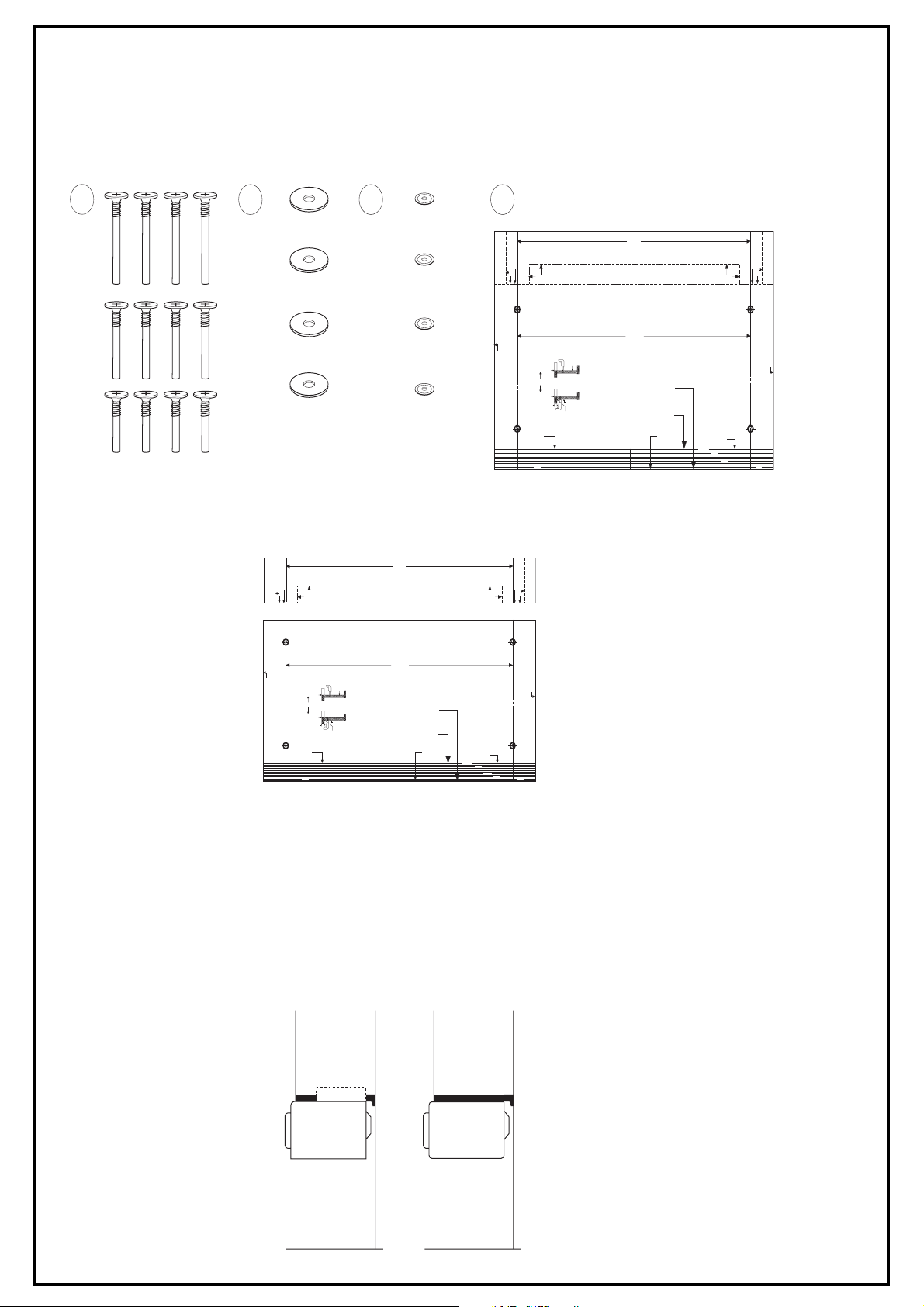
PARTS LIST
1. 3 Sets of bolts
2. 4-washers-A
3. 4-washers-B
4. 1-Template
Upon completing your check of the parts li st , read all in structi ons co mplet ely before st arting the instal lation . This wi ll help you to become
familiar with the process and make installation easier.
(
NOTE
: It is suggested that you gather all needed tools and installation parts in one location.)
1
2
43
15
25/64"
TEMPLATE 1
HOLE CENTRE LINE
DETACH
TEMPLATE 2
IMPORTANT
Read the installation booklet for complete instructions before beginning installation.
Template must lay flat against the cabinet when locating the holes.
25/64"
15
TEMPLATE
ON TOP SIDE
CABINET
(A)
FRONT
MICROWAVE SIDE
HOLE CENTRE LINE
or
CABINET
(B)
FRONT
TEMPLATE ON
BOTTOM SIDE
FRONT RAIL
THICKNESS
CUT EDGE
TEMPLATE
CUT LINES
FRONT FRONT
INSTRUCTIONS
(See installation booklet for complete instructions.)
If you drill the 4 mounting holes from the inside of the cabinet - place the
front edge of the template at the front edge of the cabinet.
Drill the 4 holes 1/4" DIA. as described in the installation instruction booklet.
If you drill the mounting holes from the bottom side of the cabinet measure the thickness of the front rail and cut that amount off the front of
the template. Use the cutting lines to insure a straight cut. Place the cut
edge against the back side of the front rail and position the template flat
against the bottom side of the cabinet.
Drill the 4 holes 1/4" DIA. as described in the installation instruction booklet.
CABINET FRONT
HOLE CENTRE LINE
DETACH
DETACHDETACH
MICROWAVE SIDE
HOLE CENTRE LINE
TEMPLATE
CUT LINES
1 1/4 INCH
1 INCH
1/2 INCH
1/4 INCH
PREPARATIONS
Open the template and detach both segments along the dashed line with scissors. You should have two separate pieces.
• Template 1
• Template 2
15
25/64"
HOLE CENTRE LINE
DETACH
Read the installation booklet for complete instructions before beginning installation.
Template must lay flat against the cabinet when locating the holes.
TEMPLATE
ON TOP SIDE
CABINET
(A)
FRONT
MICROWAVE SIDE
HOLE CENTRE LINE
or
(B)
TEMPLATE
CUT LINES
FRONT FRONT
CABINET
FRONT
TEMPLATE ON
BOTTOM SIDE
FRONT RAIL
THICKNESS
CUT EDGE
If you drill the 4 mounting holes from the inside of the cabinet - place the
front edge of the template at the front edge of the cabinet.
Drill the 4 holes 1/4" DIA. as described in the installation instruction booklet.
If you drill the mounting holes from the bottom side of the cabinet measure the thickness of the front rail and cut that amount off the front of
the template. Use the cutting lines to insure a straight cut. Place the cut
edge against the back side of the front rail and position the template flat
against the bottom side of the cabinet.
Drill the 4 holes 1/4" DIA. as described in the installation instruction booklet.
TEMPLATE 1
TEMPLATE 1
TEMPLATE 2
IMPORTANT
25/64"
15
INSTRUCTIONS
(See installation booklet for complete instructions.)
TEMPLATE 2
CABINET FRONT
1 1/4 INCH
HOLE CENTRE LINE
DETACH
DETACHDETACH
MICROWAVE SIDE
HOLE CENTRE LINE
TEMPLATE
CUT LINES
1 INCH
1/2 INCH
1/4 INCH
TWO MOUNTING METHODS
There are two mounting methods described in this booklet that can be used.
1.
Countertop Method
You can use this method if you decide not to cabinet mount your oven.
To use your oven as a countertop model, simply position the oven on the desired counter and plug the electrical cord into a three
prong (grounded)wal l rece pta cle.
2.
Cabinet Mounting Method
This method is for mounting your ov en under a cabinet and uses the temp late, 4-washers and one set of sc rews. Before using this method,
the 4 plastic plug butto ns on the top of the ov en must be removed . This ca n be done b y placi ng a thin flat bl ade sc rewdrive r bet ween th e
plug button and the oven top and raising gently, taking care to avoid acratching the oven top.
OVEN MAY BE MOUNTED TO CABINETS WITH OR WITHOUT A FRONT RAIL.
CABINET
(SIDE VIEW)
COUNTERTOP
CABINET
(SIDE VIEW)
COUNTERTOP
Page 3

DRILLING APPROACH
You have two options for drilling the mounting holes for your oven.
First, you can drill from inside of the cabinet if you have adequate space and your shelves are removable.
Second, you can drill from the bottom.
If possible, it is generally easier to work from the inside of the cabinet. Use the instructions applicable to the approach you select. Make
sure you use the template properly depending whether you drill holes from the inside or bottom side of the cabinet.
INSTRUCTIONS FOR DRILLING FROM INSIDE
If you cannot drill from the inside, go to Instructions for Drilling From Bottom.
1.
If your cabinet i s le ss tha n 35 cm (13 25/32”) deep, cut o ff the front edge of Template 2 the amount b y w hic h th e c abi net depth is less
than 35cm(13 25/32”), using the t emplate c ut line s as a fuide . Pl ace Template2 ins ide ca bin et. Cut arou nd doo r jam an d if nec essary,
corners to make template fit.(The front edge of template must be even with the front edge of the cabinet.) Place Template 2 in
cabinet.
NOTE
: For cabinets with a recessed shelf you must measure the thickness of the front rail and cut that amount off the front edge of
Template 2 using the template cut lines as a guide. This will allow Template 2 to lay flat in the shelf.
2.
If you have a partition in the cabinet, you must do the following:
• Cut Template 2 into two pieces to fit each sid e of the partition.
• Position o ne piece of Template 2 inside the ca binet, making sure that th e front edge is even with the front edge of cabinet.
• Position Template 1 on front of the cabinet so that the arrow is aligned with the hole center line on Template 2.
• Position remaining piece of Template 2 inside cabinet and align th e hole center lines with arrows on Template 1 so that
distance from right hole center to left hole center measures the distance indicated on the template. (You will have to cut
excess paper from the middle of Template 2 to make it lay flat.)
• Position the remaining piece of Template 2 inside cabinet.
• Check again to mak e sure tha t the hole center lines on Template 2 are straight an d that th e distance from the right to left
drilling holes measures the distance indicated on the template.
• Go to Drilling the Mounting Hole s.
INSTRUCTIONS FOR DRILLING FROM BOTTOM
1.
If you have a front rail, measure the thickness and cut that amount off the front edge of Template 2 using the template cut lines as a
guide.
2.
Place cut edge of Template 2 against the back side of the front rail and position it flat against the bottom side of the cabinet.
NOTE
: On some cabinets a smal l bracket or glue block is use d between the overhang and the unde rsi de of the cabinet bottom. If th is is
true of your cabinets, cut Template 2 to fit around the bracket or glue block so that it will be flat on the cabinet bottom when attached.
3.
If you have a partition you must do the following:
• Cut Template 2 into two pieces to fit on each side of the partition.
• Position one piece of Template 2 under the cabinet. (The cut line along the front edge of Template 2 must be placed
against the back of the front rail.)
• Attach Template 1 to rear of cabinet an d align arrows with hole center line on Template 2.
Page 4

• Position remaining piece of Template 2 under the cabinet and align the hole center lines with arrow s on Template 1 so
that the distance from right hole center to left hole center measures the distance indicated on the templates. (You ma y
have to cut ex c e s s paper from middle of the template to make it lay flat.)
• Position Template 2. (The cut line along the front edge of template must be placed against the bac k of the front rail.)
DRILLING THE MOUNTING HOLES
While drilling, it is recommended that safety glasses be worn to prevent possible eye damage from cabinet shavings.
1.
Use a center punch or nail to make an indentation for centering the drill bit.
2.
Drill through Template 2 at the four black drilling holes indicated on the template. (Drill should be held straight to ensure proper
alignmen t of bolts.)
3.
After drilling the four holes, remove the template and clean the drill holes.
SELECTING YOUR MOUNTING BOLTS
1.
You should have three sets of bolts of varying lengths in the installation package. select one bolt of each size.
2.
Hold each bolt against the cabin et f r ont rail. pick the bo lt that exten ds beyond top of the bottom shel f by. 48 cm (3/6") to 2.54 cm (1").
this will be the bolt length needed for your cabinets .
2.54cm~0.5cm
(1"~3/16")
NOTE
: It is important to pick the correct bolt length needed for your cabinets. If the bolt is too short it won't reach the oven. If the bolt is
too long, it will not permit oven to be drawn up to the cabinet snugly.
3.
From inside the cabinet, insert the bolts through the mounting straps and then into the drilled holes.
TOP OF BOTTOM SHELF
MOUNTING THE OVEN
To aid installatio n, we suggest th at you use so me solid suppor t such as b ooks to hold the o ven while you are securing i t with the mounting
bolts.
Make sure that whatever you use is stacked or cut as close as possible to the height needed for the oven to reach the cabinet bottom.
1.
Place the oven on the support and move into position. Lift oven, aligning the mounting holes on the oven with the bolts. Do not grip
the door handle to help lift the oven.
2.
Insert bolts into mounting hole s on the o ve n. Tighten th e bolts to se cure ov en to the bot tom of the cabin et.(Alternate bet ween bolts so
that oven is drawn up evenly.)
3.
Once oven is securely in place, plug power cord into three prong (grounded) wall receptacle.
Printed in Malaysi a
Page 5

Instrucciones de instalación
LÉALAS DETENIDAMENTE. Conserve estas instrucciones.
INSTRUCCIONES DE SEGURIDAD IMPORTANTES
ADVERTENCIA
Antes de comenzar la instalación de este kit, asegúrese de que el horno esté desenchufado.
Este horno se ha diseñado para su instalación bajo armarios de madera o metal apropiados y bien acondicionados, lo suficientemente
resistentes como para soportar los elementos que desee colocar dentro de ellos más un peso adicional de 41 kg colgado de la parte
inferior.
Vacíe el armario seleccionado y retire los objetos que pudiera haber en los armarios adyacentes.
NOTA
: La vibración producida al perforar los orificios puede dañar los elementos frágiles, como el cristal o la porcelana.)
(
Ahora proceda a inspeccionar los armarios. Si se da alguna de las siguiente circunstancias, deberá comprobar personalmente la
resistencia de éstos, o ponerse en contacto con un fabricante de armarios cualificado.
1.
Separación de las juntas entre el estante inferior y la estructura del armario.
2.
Grietas, rendijas u otros signos de deterioro.
3.
Compruebe el número de tornillos usados para instalar el armario. Si está sujeto al muro mediante sólo dos tornillos en la parte
superior, deberá añadir otros dos tornillos en la parte inferior para asegurar firmemente el armario. Al colocar estos tornillos,
asegúrese de que penetren al menos 1,3 cm en el interior del muro.
4.
En armarios de madera, el grosor del tablero o del contrachapado del estante inferior debe ser de al menos 0,48 cm.
5.
Asegúrese de que la parte inf e rior del armario teng a com o mín imo de 50 c m de a nchur a y 35 c m de profun didad. Si el armario tie ne
menos de 35 cm de profundidad, siga cuidadosamente las instrucciones de montaje si desea montar el horno bajo el armario.
Para comprobar la resistencia del armario, coloque en el estante* un peso de 40 kg, más el peso equivalente al de los objetos que
normalmente almacena en su interior, durante al menos cinco minutos.
*Puede utilizar garrafas de agua, bricks o libros para obtener el peso de prueba.
NOTA
: Si el armario está adecuadamente fabricado y convenientemente instalado soportará esta prueba sin sufrir ningún daño; sin
embargo, existe la posibili dad de que s e produ zca algún daño que pro vocaría q ue el armari o fuera inca paz de so portar el peso adicional.
Maytag Company NO SE HACE RESPONSABLE DE NINGÚN DAÑO U OTRAS CONSECUENCIAS resultantes de la realización de
esta prueba.
Si no está seguro de que sus armarios sean adecuados para este tipo de instalación, puede utilizar el horno colocándolo sobre la
encimera.
HERRAMIENTAS Y COMPONENTES
Se necesitan las siguientes herramientas para instalar la unidad:
• Taladro y broca de 0,64 cm (1/4")
• Destornilladores Phillips y de punta plana
• Clavo o punzón
• Lápiz y regla
• Tijeras
• Martillo
LISTA DE COMPONENTES DE LA INSTALACIÓN
A continuación se enumeran los componentes que podrían ser necesarios par la instalación del horno.
Saque todos los componentes de la cavidad de cocción y compárelos con la lista de componentes y con el dibujo para asegurarse de
que no falte ninguno. Aproveche esta operación para familiarizarse con cada una de las piezas.
Part No.: 8101P611-60
Código No.
: DE68-02900A
Page 6

LISTA DE COMPONENTES
1. 3 juegos de tornillos
2. 4 arandelas-A
3. 4 arandelas-B
4. 1 plantilla
Cuando haya acabado de comprobar la lista de componentes, lea completamente las instrucciones antes de comenzar la instalación.
Esto le ayudará a familiarizarse con el proceso y hará que la instalación le resulte más fácil.
(
NOTA
: Le sugerimos que reúna t odas las herr amientas necesarias y los componentes de la instal ación en un so lo lugar.)
1
2
43
15
25/64"
HOLE CENTRE LINE
DETACH
Read the installation booklet for complete instructions before beginning installation.
Template must lay flat against the cabinet when locating the holes.
TEMPLATE
ON TOP SIDE
CABINET
(A)
FRONT
MICROWAVE SIDE
HOLE CENTRE LINE
TEMPLATE
CUT LINES
FRONT FRONT
or
CABINET
(B)
FRONT
TEMPLATE ON
BOTTOM SIDE
FRONT RAIL
THICKNESS
CUT EDGE
If you drill the 4 mounting holes from the inside of the cabinet - place the
front edge of the template at the front edge of the cabinet.
Drill the 4 holes 1/4" DIA. as described in the installation instruction booklet.
If you drill the mounting holes from the bottom side of the cabinet measure the thickness of the front rail and cut that amount off the front of
the template. Use the cutting lines to insure a straight cut. Place the cut
edge against the back side of the front rail and position the template flat
against the bottom side of the cabinet.
Drill the 4 holes 1/4" DIA. as described in the installation instruction booklet.
TEMPLATE 1
TEMPLATE 2
IMPORTANT
25/64"
15
INSTRUCTIONS
(See installation booklet for complete instructions.)
CABINET FRONT
HOLE CENTRE LINE
DETACH
DETACHDETACH
MICROWAVE SIDE
HOLE CENTRE LINE
TEMPLATE
CUT LINES
1 1/4 INCH
1 INCH
1/2 INCH
1/4 INCH
PREPARACIÓN
Abra la plantilla y separe los dos segmentos a lo largo de la línea de puntos con ayuda de unas tijeras. Con ello obtendrá dos piezas
distintas.
• Plantilla 1
• Plantilla 2
15
25/64"
HOLE CENTRE LINE
DETACH
Read the installation booklet for complete instructions before beginning installation.
Template must lay flat against the cabinet when locating the holes.
TEMPLATE
ON TOP SIDE
CABINET
(A)
FRONT
MICROWAVE SIDE
HOLE CENTRE LINE
or
(B)
TEMPLATE
CUT LINES
FRONT FRONT
CABINET
FRONT
TEMPLATE ON
BOTTOM SIDE
FRONT RAIL
THICKNESS
CUT EDGE
If you drill the 4 mounting holes from the inside of the cabinet - place the
front edge of the template at the front edge of the cabinet.
Drill the 4 holes 1/4" DIA. as described in the installation instruction booklet.
If you drill the mounting holes from the bottom side of the cabinet measure the thickness of the front rail and cut that amount off the front of
the template. Use the cutting lines to insure a straight cut. Place the cut
edge against the back side of the front rail and position the template flat
against the bottom side of the cabinet.
Drill the 4 holes 1/4" DIA. as described in the installation instruction booklet.
TEMPLATE 1
TEMPLATE 1
TEMPLATE 2
IMPORTANT
25/64"
15
INSTRUCTIONS
(See installation booklet for complete instructions.)
TEMPLATE 2
CABINET FRONT
1 1/4 INCH
HOLE CENTRE LINE
DETACH
DETACHDETACH
MICROWAVE SIDE
HOLE CENTRE LINE
TEMPLATE
CUT LINES
1 INCH
1/2 INCH
1/4 INCH
DOS MÉTODOS DE MONTAJE
Puede utilizar cualquiera de los dos métodos de montaje descritos en el folleto.
1.
Método sobre encimera
Use este método si decide no montar el horno en un armario.
Para usar el horno como un modelo de encimera, colóquelo sobre la parte de la encimera que desee y conecte el cable eléctrico a
un enchufe de pared de tres orificios (con toma de tierra).
2.
Método de montaje en armario
Este método se utiliza para montar el horno en un armario, y necesita la plantilla, las 4 arandelas y el juego de tornillos. Antes de
comenzar el procedimiento, debe retirar los cuatro botones de plástico situados en la parte superior del horno. Esto se consigue
introduciendo la punt a plana de un destorn illador fino entre el botón y la parte superio r del horno y tirando su avemente, co n cuidado pa ra
no rayar la parte superior del horno.
EL HORNO PUEDE MONTARSE EN ARMARIOS CON O SIN TOPE FRONTAL.
CABINET
(SIDE VIEW)
COUNTERTOP
CABINET
(SIDE VIEW)
COUNTERTOP
Page 7

MÉTODOS DE TALADRADO
Existen dos opciones para perforar los orificios de montaje para el horno.
La primera consiste en perf orar de sde el interior del armario, en c as o de qu e dis ponga del espacio adecu ado para hac erlo y de q ue los
estantes sean desmontables.
La segunda consiste en perforar desde la parte inferior.
Por lo general, es más fácil trabajar desde el interior del armario, si ello es posible. Siga las instrucciones que correspondan al método
que haya elegido. Asegúrese de que utiliza la plantilla adecuada, según el lugar desde donde perfore los orificios del armario.
INSTRUCCIONES PARA EL TALADRADO DESDE EL INTERIOR
Si no puede taladrar desde el interior, siga las "Instrucciones para el taladrado desde la parte inferior".
1.
Si su armario tiene menos de 35 cm de profundidad, corte de la parte frontal de la plantilla 2 la medida en que la profundidad del
armario sea menor de 35 cm; utilice para ello las líneas de corte de la plantilla como referencia. Coloque la plantilla 2 dentro del
armario. Recorte alrededor de los cierres de la puerta y de las esquinas, si es necesario, para conseguir que la plantilla ajuste (el
borde frontal de la plantilla debe estar igualado con el borde frontal del armario). Coloque la plantilla 2 dentro del armario.
NOTA
: En armarios con un estante empotrado, debe medir el grosor del tope frontal y recortar esta cantidad del borde frontal de la
plantilla 2 usando las líneas de corte de la plantilla como guía. Esto permitirá que la plantilla 2 pueda colocarse plana en el estante.
2.
Si el armario tiene una partición, deberá hacer lo siguiente:
• Corte la plantilla 2 en dos partes que se ajusten a cada lado de la pa rtición.
• Coloque una pieza de la plantilla 2 d entro del armario, comprobando que el borde frontal esté igualado con el borde
frontal del armario.
• Coloque la plantilla 1 en el frente del armario, de manera la flecha se alinee con la línea del centro del orificio de la
plantilla 2.
• Coloque la otra pieza de la plantilla 2 dentro del armario y alinee las líneas del centro de los orificios con las flechas de
la plantilla 1 de manera q ue la d istancia desde el cen tro del orificio derecho al cen tro del orificio izquierdo coincida con la
distancia indicada en la plantilla. (Deberá cortar el papel sobrante de la parte media de la plantilla 2 para p e rmitir que
ésta se pueda colocar plana.)
• Coloque la otra pieza de la plantilla 2 dentro del armario.
• Haga una nuev a comprob ación para asegurarse de que las líneas del centro de los orificios de la plantilla 2 esté n rectas
y que la distancia entre los orificios de perforación izquierdo y derecho coincide con la distancia indicada en la plantilla.
• Vaya a "Taladrado de los orificios de montaje"
INSTRUCCIONES PARA EL TALADRADO DESDE LA PARTE INFERIOR
1.
Si existe un tope frontal, mida su grosor y recorte esta cantidad del borde frontal de la plantilla 2 usando las líneas de corte de la
plantilla como guía.
2.
Coloque el borde de corte de la plantilla 2 contra el lado posterior del tope frontal y sitúela, procurando que quede plana, contra la
cara inferior del armario.
NOTA
: En algunos armarios se utiliza un pequeño soporte o bloque encolado entre la parte que sobresale y la superficie de debajo de
la parte inferior del armario. Si su armario es de este tipo, corte la plantilla 2 para ajustarla alrededor del soporte o bloque encolado, de
manera que, cuando se coloque, quede plana sobre la parte inferior del armario .
3.
Si hay una partición, deberá hacer lo siguiente:
• Corte la plantilla 2 en dos piezas que se ajusten a cada lado de la partición.
• Coloque una pieza de la plantilla 2 d entro del armario. (La línea de corte que discurre a lo largo del borde frontal de la
plantilla 2 debe quedar tocando a la parte posterior del tope frontal.)
• Junte la plantilla 1 a la parte posterior del armario y alinee las flechas con la línea de centro del orificio de la plantilla 2.
Page 8

• Coloque la otra pieza de la plan tilla 2 debajo del armario y alinee las líneas del centro de los orificios con las flechas de
la plantilla 1 de manera q ue la d istancia desde el cen tro del orificio derecho al cen tro del orificio izquierdo coincida con la
distancia indicada en las plantillas. (Quizá deba cortar el papel sobrante de la parte media de la plantilla para permitir
que ésta se pueda colocar plana.)
• Coloque la plantilla 2. (La línea de corte que discurre a lo largo del borde frontal de la plantilla debe quedar tocando a la
parte posterior del tope frontal.)
TALADRADO DE LOS ORIFICIOS DE MONTAJE
Se recomienda el us o de gafas de seguridad al perforar el armario, a fin d e p r ev eni r l as posibles lesio nes oc ul are s d ebidas a las virutas
que puedan saltar.
1.
Utilice un clavo o punzón para hacer una muesca que permita centrar la broca.
2.
Perfore los cuatro orificios posteriores indicados en la plantilla 2, a través de la propia plantilla. (Mantenga el taladro en posición
recta para que los tornillos se alineen correctamente.)
3.
Después de perforarlos, retire la plantilla y limpie los cuatro orificios.
SELECCIÓN DE LOS TORNILLOS E MONTAJE
1.
El paquete de instalación contiene tres juegos de tornillos de diferentes longitudes: seleccione un tornillo de cada tamaño.
2.
Sostenga cada tornillo contr a el tope frontal del armario; elija el tornillo que sobresalga de la parte de arriba del estante i nf erior en tre
0,48 cm y 2,54 cm: estos serán los tornillos que tendrá que utilizar en sus armarios.
sobresalga de la parte de
2.54cm~0.5cm
(1"~3/16")
NOTA
: Es importante que elij a los tornil los de longitu d correcta. Si el tornillo es demasiad o corto no al canzará al horno. Si es demasiado
arriba del estante inferior
largo, no permitirá que el horno se aloje cómodamente en el armario.
3.
Desde el interior del armario, inserte los tornillos a través de las tiras de montaje y después a través de los orificios.
MONTAJE DEL HORNO
Para facilitar la instalación, sugerimos que utilice algún tipo de soporte rígido, tal como unos libros, para sostener el horno mientras lo
asegura con los tornill os de mo ntaje.
Asegúrese de que el sopo rte que utilice se acerqu e lo más posible de la altur a necesaria para que el horno pueda alcanzar la pa rte inferior
del armario.
1.
Coloque el horno en el soporte, en la posición correcta. Empuje el horno hasta alinear los orificios de montaje de éste con los
tornillos. No empuje el horno tomándolo por la manilla de la puerta.
2.
Inserte los tornillos en los orificios de montaje del horno. Apriete los tornillos para asegurar el horno a la parte inferior del armario
(alterne entre e llos a la hora de apretarlos para que el horno quede uniformemente ajustado).
3.
Cuando el horno esté co rrectamen te colocado, conecte el cable de ali mentación a un enchufe de pared de tres orificios (con toma de
tierra).
Impreso en Malasia.
 Loading...