

Amana Am33lp Owner's Manual

Amana™SS 5 Burner Grill w/ Rear Burner
USE AND CARE MANUAL
FOR OUTDOOR USE ONLY
ALWAYS KEEP YOUR GRILL COVERED WHEN NOT IN USE
BEFORE YOU BEGIN – We’ ve included easy-to-follow, step-by-step instructions which have been carefully written to
ensure quick assembly of your grill. Reading the instructions will be a time saver in the end.
TOOLS YOU WILL NEED – A Phillips screwdriver, adjustable wrench, 1/2” wrench or socket and a 1/4” nut driver or
socket will be needed to assemble this grill. All other necessary hardware has been included.
Questions,Missing or Damaged part? DO NOT RETURN PRODUCT TO STORE
Were here to help. Just call 1-800-229-5647. For faster service, have model number and
serial number on hand when calling.

IMPORTANT SAFETY INFORMATION
- Read this manual carefully before using your grill to reduce the risk of fire, burn
hazard or other injury.
- Extreme care should be used because of the high temperatures produced by this
appliance. CHILDREN SHOULD NOT BE LEFT UNATTENDED IN AN AREA
WHERE THE GRILL IS BEING OPERATED.
- This appliance must be kept clear from combustible materials, gasoline or other flammable vapors and liquids. Do not
allow flammable materials to come in contact with grate, burner or hot surfaces.
- Use only outdoors and provide good ventilation to avoid carbon monoxide build-up which could result in injury or death.
- Do not repair or replace any part of this appliance unless it is specifically recommended in this manual. A qualified
service technician should conduct all other service.
- Follow the installation and servicing instructions provided with this product. Have your grill installed by a qualified
service technician.
- Locate the main gas supply valve so that you know how to shut the gas off to your grill.
- If you smell gas, make sure all gas connections are tight before operation. If you continue to smell gas call a
qualified technician.
- When lighting a burner, always pay close attention to what you are doing and be certain you are pushing the igniter
that lights the burner you intend on using.
- Always keep your face and body as far away as from the grill as possible when lighting to reduce the risk of burn.
- Extinguish all flames and do not smoke while engaging gas and igniting the grill.
- A minimum distance of at least 12" must be maintained from any combustible material on both sides and the back of
the grill. Do not place the grill under any overhead unprotected combustible construction.
RECOGNIZE SAFETY SYMBOLS, WORDS AND LABELS
WARNING indicates a potentially hazardous situation which, if
not avoided, could result in death or serious injury.
NOTE indicates an important piece of information that needs to
be observed to ensure the proper operation of your grill.
INSTALLER: Please retain these instructions with the owner so that they may maintain them for
future reference.
2

Welcome & Congratulations
Congratulations on your purchase of a new grill! We are
very proud of our product and we are completely
committed to providing you with the best service
possible. Your satisfaction is our #1 priority.
Please read this Use & Care Manual very carefully. It
contains valuable information on how to properly
maintain your new grill.
We know you’ ll enjoy your new grill and thank you for
choosing our product. We hope you consider us for
future purchases.
PLEASE READ AND SAVE THESE INSTRUCTIONS
This Use & Care Manual provides specific operating
instructions for your model. Use your grill only as
instructed in this manual. These instructions are not
meant to cover every possible condition and situation
that may occur. Common sense and caution must be
practiced when installing, operating and maintaining any
appliance.
Please record your model and serial numbers below for
future reference. This information is found on the serial
plate located on the inside of the grill door.
Questions?
1-800-229-5647
for written inquiries:
Sure Heat Manufacturing
3130 Moon Station Rd
Kennesaw, GA 30144
Register Your Product
The PRODUCT REGISTRATION CARD
should be filled in completely, signed
and returned to Sure Heat Manufacturing.
NOTE: Use only soap and water to clean serial plate.
Model Number: ______________________________
Serial Number: ______________________________
Purchase Date: ______________________________
Gas Type: __________________________________
Please complete and mail in the Product
Registration Card included with your grill.
Please retain this manual for future reference
Please attach sales receipt here for
future reference.
Amana™is a registered trademark of the Maytag Corporation and is used under license
to Sure Heat Manufacturing
© 2007 Sure Heat Manufacturing All rights reserved
3

General Safety Instructions
Do not use the rotisserie in the rain.
Electrical Grounding Instructions
This appliance (rotisserie motor) is equipped with a
three-prong (grounding) plug for your protection
against shock hazard and should be plugged directly
into a properly grounded three-prong receptacle. Do
not cut or remove the grounding prong from this plug.
Keep any electrical supply cords and the fuel supply
hose away from any heated surfaces.
The Spare L.P. Gas Tank Barrier must be installed to
prevent storage of spare L.P. Gas Tanks. Failure to
comply with these instructions could result in a fire or
explosion that could cause serious bodily injury, death,
or property damage.
FOR YOUR SAFETY
If you smell gas:
1. Shut off gas to the appliance.
2. Extinguish any open flames.
3. Open grill hood.
4. If odor continues, immediately
call your gas supplier and local Fire Dept.
NOTE: Do Not operate the main burners and infrared
back burner at the same time. This can cause warping of
the roll top grill hood.
Do not use the grill in garages, breezeways, sheds or any
enclosed area. Never operate the grill in enclosed areas as
this could lead to a carbon monoxide buildup, which could
result in injury or death. Place the grill on a level surface.
Avoid moving the grill while it is operation.
Always have a qualified service technician perform difficult
conversions or modifications.
Never attach an unregulated gas line to the appliance.
Connection to an unregulated gas line can cause excessive
heat or fire.
TESTED IN ACCORDANCE WITH ANSI
Z21.58b-2002/CSA 1.6b-M02 STANDARD FOR
OUTDOOR COOKING GAS APPLIANCES. THIS
GRILL IS FOR OUTDOOR USE ONLY.
Check your local building codes for the proper method of
installation. In the absence of local codes, this unit should be
installed in accordance with the
National Fuel Gas Code No. Z223.1-2002 and the
National Electrical Code ANSI/NFPA No. 70-1990
CALIFORNIA PROPOSITION 65 - WARNING: The
Burning of gas cooking fuels generates some
by products which are on the list of substances which are
known by the State of California to cause cancer or
reproductive harm. California law requires businesses to
warn customers of potential exposure to such substances.
To minimize exposure to these substances, always operate
this unit according to the use and care manual, provide
good ventilation when cooking with gas.
This appliance is not intended to be installed in or
on recreational vehicles or boats.
FOR YOUR SAFETY
DO NOT store or use gasoline or other flammable vapors
and liquids in the vicinity of this or any other appliance.
An LP cylinder not connected for use shall not be stored in
the vicinity of this or any other appliance.
DO NOT try lighting this appliance without reading the
“ LIGHTING INSTRUCTIONS” section of this manual.
FOR OUTDOOR USE ONLY
4
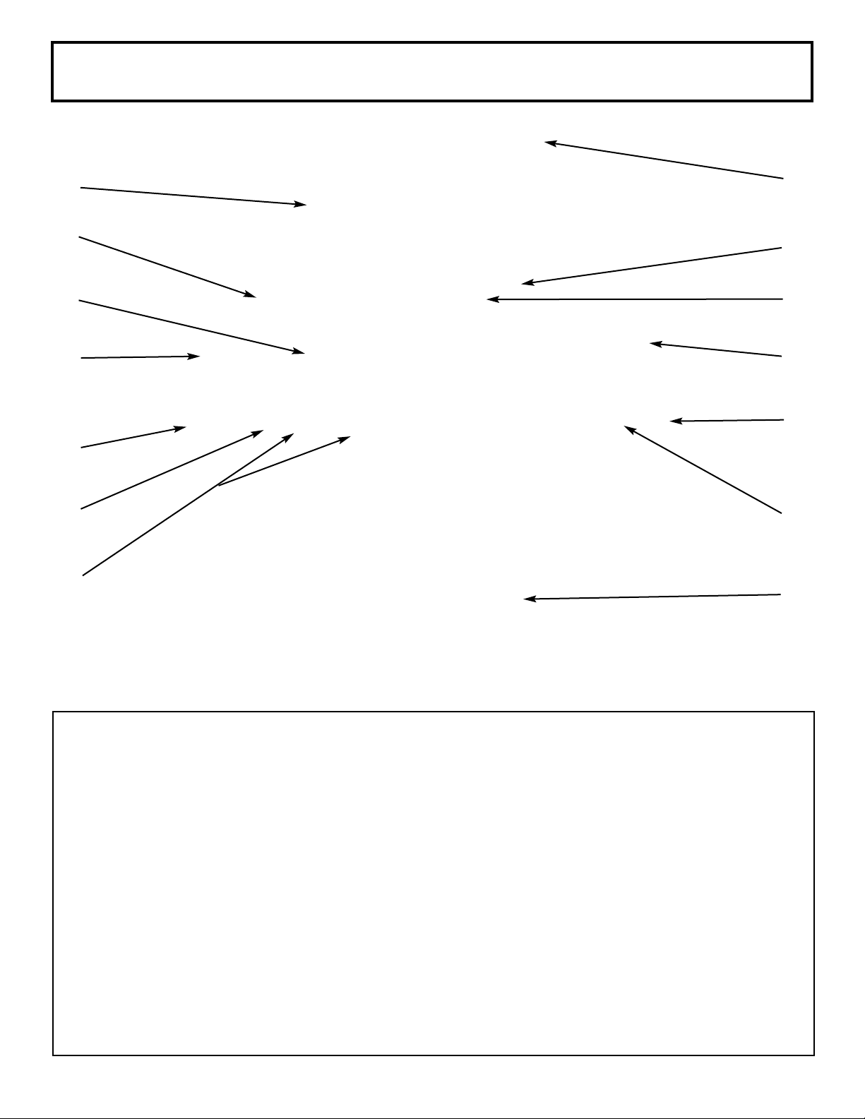
SS 5 Grill Features
1
2
3
4
8
9
10
11
12
5
6
13
7
14
1. Roll top grill hood
2. Rotisserie kit
3. Grilling/cooking surface
4. Side shelf
5. Towel bar/utensil hanger
6. Control knob: Rear infrared burner
7. Control knobs: main burners
8. Hood Handle
9. Warming shelf
10. Rear Infrared burner
11. Side burner
12. Control knob: side burner
13. Electronic igniter: main burners, side burner
and rear infrared burner
14. Cart with doors
5

Getting Started
All hardware is shown actual size.
49600206 Caster Assembly Nuts x6
49600113 Self-Tapping Screws x13
Two People Required to Assemble Grill
Tools Needed:
Phillips screwdriver
Adjustable wrench
1/2” wrench or socket
1/4” nut driver or socket
49600101 "S" Hooks x3
6
12c
3e
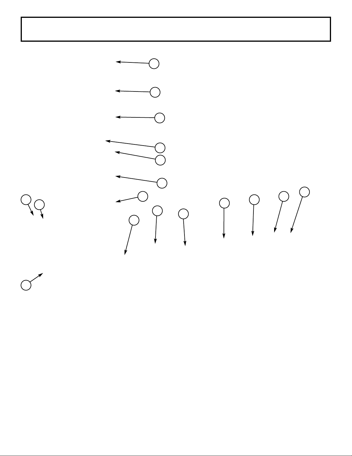
SS 5 Grill Out of Box
2a
12b
2c
5a
5b
2e
11b
1a
11a
7
12a
6
1b
1c
4a
2a. Cart Side Left
12b. Main Cooking Grate
2c. Cart Side Right
5a. Cart Door Left
5b Cart Door Right
2e. Cart Back
1a. Cart Base
12c. Bread Warmer Grate
3e. Spare LP Gas Tank Barrier
4a Grill Assembly
11b Drip Pan
7 Side Burner Shelf Assembly
12a Flavor Grid
11a Condiment Basket
6 Side Shelf Left Assembly
1b Caster Assembly Left (Swivel Wheels)
1c Caster Assembly Right (Swivel Wheesl with lock)
Not Shown: Plastic bag containing:
Igniter Wire
Screw Packages
Side Burner Igniter
Side Burner Knob
Side Burner Bezel
Tank Ring
Open Box Carefully – Lay Out All Parts
7

SS 5 Assembly
STEP ONE
a. Set the cart base on the floor and then lay the
caster assembly left on the left side and the caster assembly right on the right side of the cart
base. The large hole in the cart base will be
towards the rear of the base.
b. Pick up the left side of the cart base and set the
caster assembly left in place by inserting the
attached bolts through the three (3) holes in the
cart base.
c. Pick up the right side of the cart base and set the
caster assembly right in place by inserting the
attached bolts through the three (3) holes in the
cart base.
1b
1a
1c
8

SS 5 Assembly
STEP TWO
a. Place the cart side left onto the two (2) outer fixed
caster assembly bolts, make sure the large flange
is toward the front of the cart base.
b. Secure the cart side left in place by hand tightening
the caster assembly nuts onto the caster
assembly bolts.
c. Place the cart side right onto the two (2) outer
swivel caster assembly bolts, make sure the large
flange is toward the front of the cart base.
d. Secure the cart side right in place by hand
tightening nuts onto the caster assembly bolts.
e. Place the cart back onto the two (2) rear caster
assembly bolts.
f. It will be necessary to push the top of the left and
right cart sides outward slightly to get the cart
back down completely on the cart base.
2a
2f
2e
2b
2c
2d
9
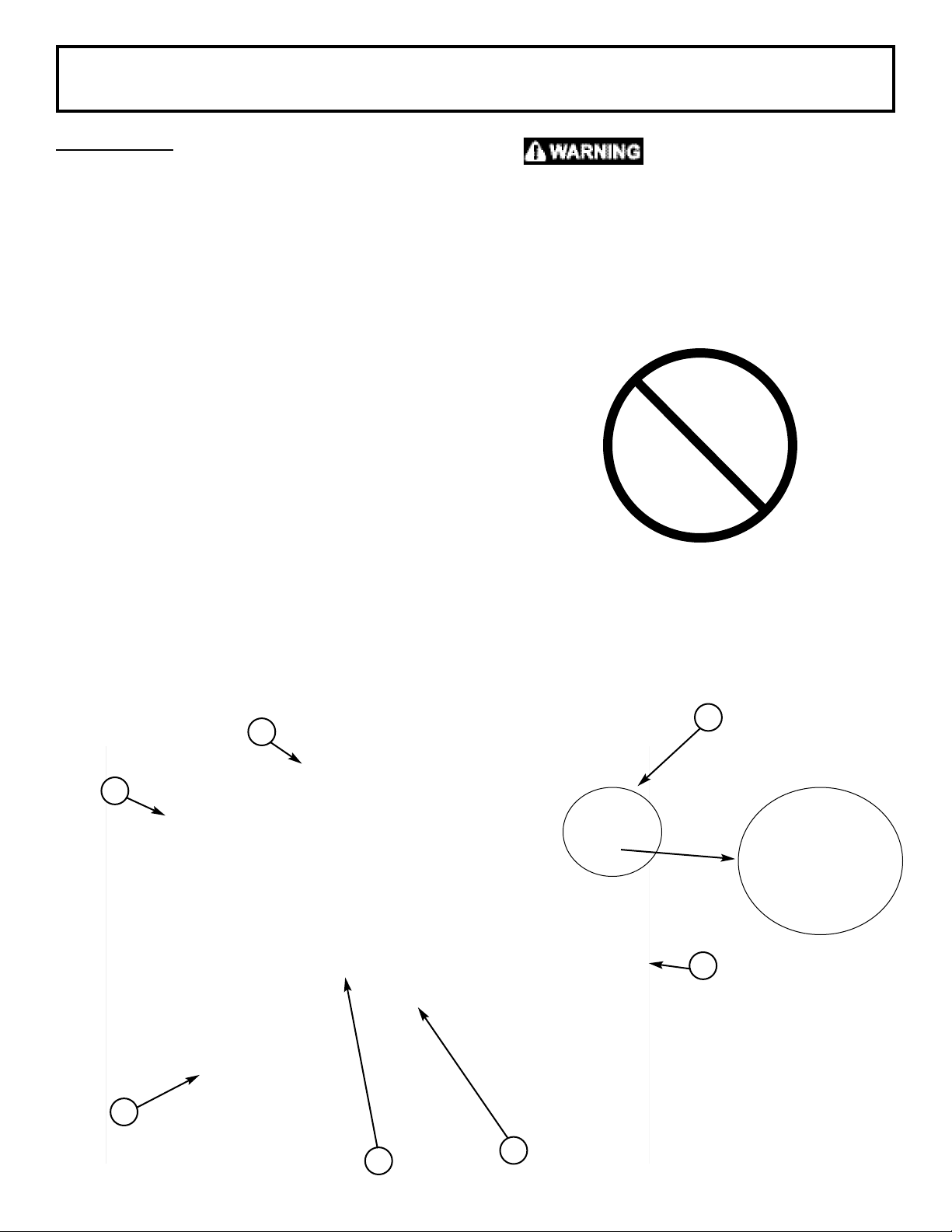
SS 5 Assembly
STEP THREE
a. Press the cart sides back together making sure
that the cart back flange cover the cart side
flanges.
b. Attach three (3) self tapping screws through the
pre-drilled holes on the cart back into the cart
side left. Repeat for cart side right.
c. Fasten two (2) caster assembly nuts onto the back
caster assembly bolts.
d. Tighten all six (6) caster assembly nuts with a
wrench.
e. Attach the Spare L.P. Gas Tank Barrier by
inserting the tabs into the slots in the cart base
and then attach the flat end of the
barrier to the pre-drilled hole in the cart back
with a self-tapping screw.
The Spare L.P. Gas Tank
Barrier must be installed
to prevent storage of spare L.P. Gas
Tanks. Failure to comply with these
instructions could result in a fire or
explosion that could cause serious
bodily injury, death, or property
damage.
3b
3a
3a
3b
3d
3c
3e
10
 Loading...