

Page 1
Amana
M
T
SS 4 Burner Gas Grill
USE AND CARE MANUAL
FOR OUTDOOR USE ONLY
ALWAYS KEEP YOUR GRILL COVERED WHEN NOT IN USE
BEFORE YOU BEGIN – We’ve included easy-to-follow, step-by-step instructions which have been carefully written to
ensure quick assembly of your grill. Reading the instructions will be a time saver in the end.
YOU WILL NEED – A Phillips scre
needed to assemble this grill. All other necessary hardware has been included.
re here to help
QUESTIONS? – W
number handy when calling.
e’
wdriver, adjustable wrench, 1/2 wrench or socket and a 1/4” nut driver or socket will be
aster service, have the model number and serial
or f
ust call 1-800-320-0859.
J
.
F
Page 2

Page 3
Welcome & Congratulations
Register Your Product
The PRODUCT REGISTRATION CARD
should be filled in completely, signed
and returned to Electrolux Home
Products North America.
Congratulations on your purchase of a new grill! We at
ure Heat Mfg. are very proud of our product and we
S
are completely committed to providing you with the best
ervice possible. Your satisfaction is our #1 priority.
s
Please read this Use & Care Manual very carefully. It
contains valuable information on how to properly
maintain your new grill.
We know you’ll enjoy your new grill and thank you for
choosing our product. We hope you consider us for
future purchases.
PLEASE READ AND SAVE THESE INSTRUCTIONS
This Use & Care Manual provides specific operating
instructions for your model. Use your grill only as
instructed in this manual. These instructions are not
meant to cover every possible condition and situation
that may occur. Common sense and caution must be
practiced when installing, operating and maintaining any
appliance.
Please record your model and serial numbers below for
future reference.This information is found on the serial
plate located on the back of the built-in grill .
Questions?
1-800-320-0859
Register Your Product
The PRODUCT REGISTRATION CARD
should be filled in completely signed
and returned to Sure Heat Manufacturing.
NOTE: Use only soap and water to clean serial plate.
Model Number: ______________________________
Serial Number: ______________________________
Purchase Date: ______________________________
Type: __________________________________
Gas
Please complete and mail in the
Registration Card
included with your grill.
Please retain this manual for future reference
Please attach sales receipt here for
future reference.
Product
AmanaTMis a registered trademark of the Maytag Corporation and is used under license
ing
actur
to Sure Heat Man
© 2006 Sure Heat Manufacturing All rights reserved
uf
1
Page 4

General Safety Instructions
IMPORTANT SAFETY INFORMATION
- Read this manual carefully before using your grill to reduce the risk of fire, burn
hazard or other injury.
- Extreme care should be used because of the high temperatures produced by this
appliance. CHILDREN SHOULD NOT BE LEFT UNATTENDED IN AN AREA
WHERE THE GRILL IS BEING OPERATED.
- This appliance must be kept clear from combustible materials, gasoline or other flammable vapors and liquids. Do not
allow flammable materials to come in contact with grate, burner or hot surfaces.
- Use only outdoors and provide good ventilation to avoid carbon monoxide build-up which could result in injury or death.
- Do not repair or replace any part of this appliance unless it is specifically recommended in this manual. A qualified
service technician should conduct all other service.
- Follow the installation and servicing instructions provided with this product. Have your grill installed by a qualified service
technician.
- Locate the main gas supply valve so that you know how to shut the gas off to your grill.
- If you smell gas, make sure all gas connections are tight before operation. If you continue to smell gas call a qualified
technician.
- When lighting a burner, always pay close attention to what you are doing and be certain you are pushing the igniter that
lights the burner you intend on using.
- Always keep your face and body as far away as from the grill as possible when lighting to reduce the risk of burn.
- Extinguish all flames and do not smoke while engaging gas and igniting the grill.
FOR YOUR SAFETY
If you smell gas:
1. Shut off gas to the appliance.
2. Extinguish any open flames.
3. Open grill hood.
4. If odor continues, immediately
call your gas supplier.
CALIFORNIA
The Burning of gas cooking fuels generates some by
products which are on the list of substances which
are known by the State of California to cause cancer
or reproductive harm. California law requires businesses to warn customers of potential exposure to
such substances.
substances, always operate this unit according to the
use and care manual, provide good ventilation when
cooking with gas.
PROPOSITION 65 - WARNING:
o minimize exposure to these
T
This appliance is not intended to be
installed in or on recreational
vehicles or boats.
TESTED IN ACCORDANCE WITH ANSI
Z21.58b-2002/CGA 1.6b-M02 STANDARD FOR
OUTDOOR COOKING GAS APPLIANCES.
THIS GRILL IS FOR OUTDOOR USE ONLY.
Check your local building codes for the proper
method of installation. In the absence of local
codes, this unit should be installed in accordance
with the National Fuel Gas Code No. Z223.1-2002
and the National Electrical Code ANSI/NFPA
No. 70-1990
FOR YOUR SAFETY
DO NOT store or use gasoline or other flammable vapors
and liquids in the vicinity of this or any other appliance.
An LP cylinder not connected for use shall not be stored in
the vicinity of this or any other appliance.
WARNING
DO NOT
the
“LIGHTING INSTRUCTIONS” section of
try lighting this appliance without reading
this manual.
FOR OUTDOOR USE ONLY
2
Page 5
Grill Features
1
2
3
4
5
6
7
10
11
8
9
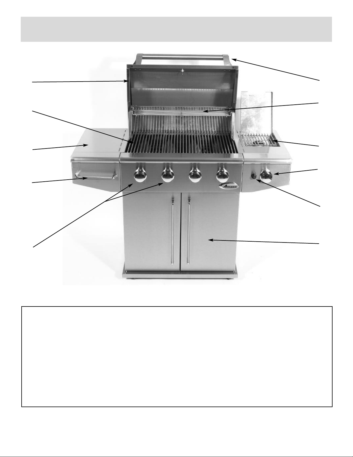
1. Roll top grill hood
2. Grilling/cooking surface
3. Side shelf
4. Towel bar/utensil hanger
5. Control knobs: main burners
6. Hood Handle
7. Warming shelf
8. Electronic igniter: main & side burner
9. Cart with doors
10. Side burner
11. Control knob: side burner
3
Page 6
Assembly
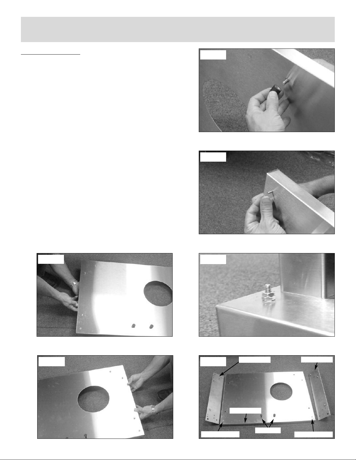
CART ASSEMBLY
1. Attach two (2) rubber door stops to top center of
cart base using supplied bolts. (See Fig. 1)
2. Install door pivot screws into front left and front right
holes. Secure each screw in place with two (2) nuts.
Make sure to tighten 1 nut on top of the other. (See
Fig. 2-3)
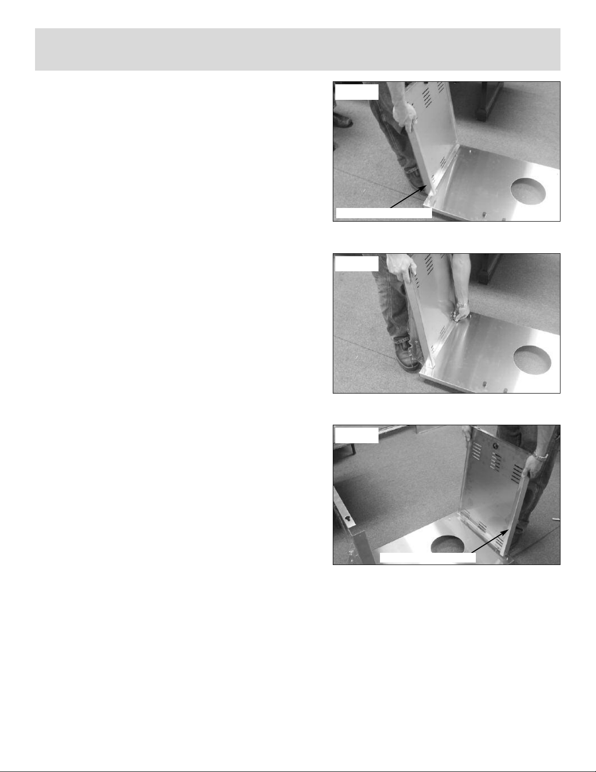
3. Set the cart base on the floor and then lay the fixed
wheel channel on the left and the swivel wheel
channel on the right side of the cart base.
(See Fig. 4)
4. Pick up the left side of the cart base and set the
wheel channel in place by inserting the attached
bolts through the three (3) holes in the cart bottom.
(See Fig. 5)
5. Pick up the right side of the cart base and set the
swivel wheel channel in place by inserting the
attached bolts through the three (3) holes in the
cart bottom. (See Fig. 6)
Fig. 1
Fig. 2
Fig. 5
Fig. 6
Fig. 3
Fig. 4
Fixed Wheels
Front Of Grill
Swivel Wheels
w
Door Piv
4
ot Scre
Door Stops
Door Piv
ot Scre
w
Page 7
Assembly
6. Place the left cart side onto the two (2) outer fixed
wheel channel bolts, make sure the large flange is
toward the front of the cart base. (See Fig. 7)
7. Secure the left cart side in place by hand tightening
nuts onto the wheel channel bolts. (See Fig. 8)
8. Place the right cart side onto the two (2) outer
swivel wheel channel bolts, make sure the large
flange is toward the front of the cart base.
(See Fig. 9)
9. Secure the right cart side in place by hand tightening
nuts onto the wheel channel bolts. (See Fig. 8)
Fig. 7
Large Flange Toward Front
Fig. 8
Fig. 9
Large Flange
oward Front
T
5
Page 8
Assembly
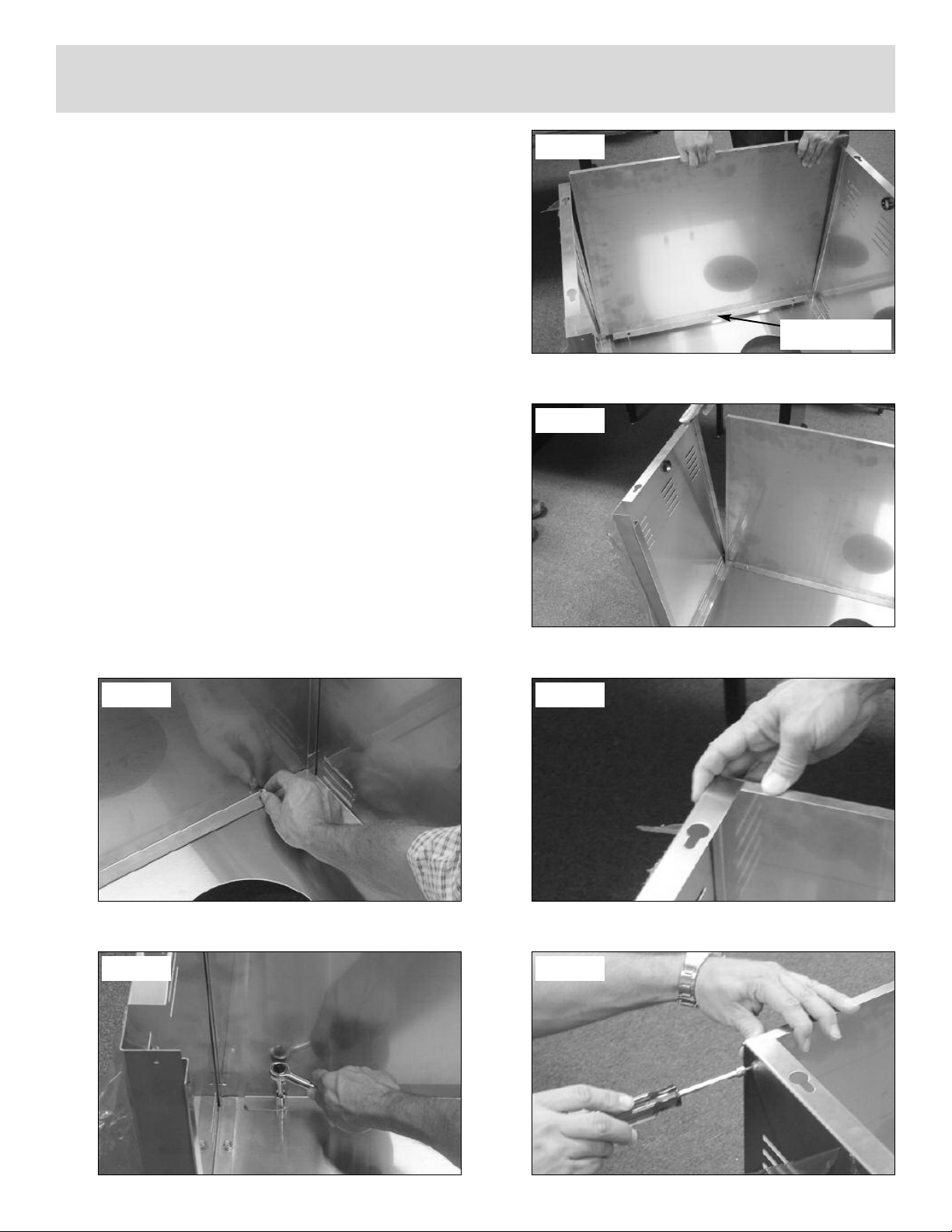
10. Place the cart back onto the two (2) rear wheel
channel bolts. (See Fig. 10)
11. It twill be necessary to push the top of the left
and right sides outward slightly to get the cart
back down completely on the base. (See Fig. 11)
12. Press the sides back together making sure that
the side flanges cover the cart back flange.
(See Fig. 12)
13. Attach three (3) self tapping screws through the
left cart side into the cart back. Repeat for right
cart side. (See Fig. 13)
14. Fasten two (2) nuts onto the back wheel channel
bolts. (See Fig. 14)
15. Tighten all six (6) wheel channel nuts with a
wrench. (See Fig. 15)
Fig. 10
Large Flange With
Holes On Bottom
Fig. 11
Fig. 14
Fig. 15
Fig. 12
Fig. 13
6
Page 9
Assembly
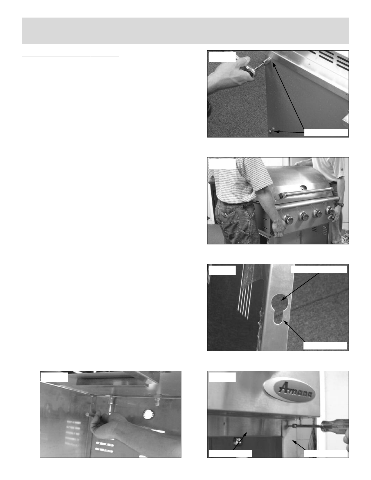
MOUNTING GRILL TO CART
1. Loosen the four (4) grill mounting bolts so that there
is approximately 1/4” between the bolt head and grill
bottom. (See Fig. 16)
2. Have someone help you pick up the grill and set it
squarely on top of the cart. (See Fig. 17)
3. Make sure the four (4) bolts fall through the large
opening on the key hole slots on the sides of the
cart. (See Fig. 18)
4. Slide the grill forward in the key hole slots until the
front grill flange rests against the side cart flanges.
(See Fig. 19)
5. Install two (2) self tapping screws into the top left
and right cart flanges. (See Fig. 19)
6. Tighten the four (4) grill head mounting bolts under-
neath the grill to secure the grill to the car
t.
(See Fig. 20)
Fig. 16
Mounting Bolts
Fig. 17
Fig. 18
Fig. 19Fig. 20
Bolt Head Inserted Here
Key Hole Slot
ront Grill Flange
F
7
Side Car
t Flange
Page 10

Assembly
7. Using the four (4) long self tapping screws, install
the door catch magnets to the bottom of the front
grill flange. Start one screw and then the other
before tightening. Make sure to install the screws
at a slight angle as shown. (See Fig. 21)
8. Place left hand door on an angle over the left side
door pivot. (See Fig. 22)
9. Tilt the top of the door toward the grill, while
depressing the top door pivot pin above the door
edge. (See Fig. 23)
10. Move the door slightly until the pin locks into place
in the hole on top of the door. (See Fig. 24)
11. Repeat steps 8-10 for right door installation.
Fig. 21
Install Screws At
An Angle
Fig. 22
Fig. 23
Fig. 24
8
Page 11

Assembly
SHELF HANDLE ASSEMBLY
1. Lay the left shelf on its side with the shelf hooks facing
up. Attach one of the handle ends to the front of the
shelf using the supplied phillips head screw.
(See Fig. 25)
2. Set the handle bar into the second handle end and
then press into the previously installed handle end.
(See Fig. 26)
3. Attach the second handle end while holding the
assembly in place using the supplied phillips head
screw. (See Fig. 27)
LEFT SHELF ASSEMBLY
1. Place a piece of styrofoam from the packaging
inside the grill to leave the grill hood propped open
slightly. (See Fig. 28)
2. Attach the left shelf by inserting the four shelf hooks
into the slots on the side of the grill. (See Fig. 28)
3. After inserting the four shelf hooks, press the shelf
against the grill and press downward until the shelf
locks in place. Make sure the top trim strip is hanging all the way inside of the grill before pressing
downward. (See Fig. 29)
4. Install one self tapping screw into the bottom front
hole of the shelf to lock the shelf in place.
(See Fig. 30)
Fig. 29
Fig 25
Fig 26
Fig. 27
Fig. 30
oam Under Hood
Fig. 28
9
Styrof
op Trim Strip
T
Page 12

Assembly
SIDE BURNER ASSEMBLY
1. Lay the side burner on its side with the shelf hooks
pointing up. Slide the valve assembly through the
center hole in the front of the shelf. Make sure the
flared fitting on the valve is facing toward the bottom
of the shelf. (See Fig. 31)
2. Insert one valve screw through the bezel and in to
the side burner valve and tighten. Make sure the
bezel is installed correctly with the H facing the
igniter hole. (See Fig. 32)
3. Insert the second valve screw through the bezel and
into the side burner valve. Tighten both screws
securely. (See Fig. 32)
4. Press the side burner assembly into the side burner
tray and install two (2) self tapping screws.
(See Fig. 33-34)
Fig. 31
Flared Fitting
Fig. 32
“H” On Bezel
Facing Igniter
Hole
Fig. 33
Fig. 34
10
Page 13

Assembly
5. Place the electronic igniter into the other hole on the
front of the side burner shelf. (See Fig. 35)
6. Secure the igniter in place using the plastic lock nut.
Make sure to tighten securely. (See Fig. 36)
7. Install AA battery, negative side first. (See Fig. 37)
8. Install spring and cap assembly and tighten securely.
(See Fig. 36)
9. Press the side burner control knob in place, making
sure to line up the flat side of the valve stem with
the flat side of the knob stem. (See Fig. 39)
Fig. 35
Fig. 36
Fig. 39
Fig. 37
Fig. 38
11
Page 14

Assembly
10. Place a piece of styrofoam from the packaging in
the grill to leave the grill hood propped open slightly.
(See Fig. 40)
11. Attach the right side burner by inserting the four
shelf hooks into the slots on the side of the grill.
(See Fig. 40)
12. After inserting the four shelf hooks, press the shelf
against the grill and press downward until the shelf
locks in place. Make sure the top trim strip is
hanging all the way inside of the grill before
pressing downward. (See Fig. 41)
13. Place the side burner head onto the side burner
tray, making sure to line up the electrode with the
large “U” shaped gap in the side burner head. (See
Fig. 42)
14. Center the burner cap on top of the side burner
head. (See Fig. 43)
Fig. 40
Fig. 41
Top Trim Strip
15. Place the side burner grate on to the side burner
tray. (See Fig. 44)
Fig. 42
Fig. 43Fig. 44
12
Page 15

Assembly
CONNECTING IGNITER WIRES
1. Attach the large connector of the loose packaged
side burner wire to the terminal under the side
burner head. (See Fig. 45)
2. Connect the other end of the side burner wire to
one of the outlets on the electronic igniter. NOTE: It
does not matter which wire goes where on the electronic igniter. (See Fig. 46)
3. Plug the remaining wires coming out of the side of
the grill into the terminals of the electronic igniter.
(See Fig. 46)
Fig. 45
Fig. 46
13
Page 16

Assembly
ATTACHING THE HOSE AND REGULATOR
ASSEMBLY
1. Feed the longer hose of the dual hose and regulator
assembly through the grommeted hole in the right
side of the cart. (See Fig. 47)
2. Attach the fitting to the side burner valve and tighten securely with a wrench. (See Fig. 48)
3. Attach the remaining shorter hose to the main inlet
fitting on the bottom of the grill and tighten securely
with a wrench. (See Fig. 49)
ATTACHING CONDIMENT BASKET AND TOOL
HANGERS
1. Slide the condiment basket into the slots located
inside of the left hand cart door. (See Fig. 50)
Fig. 47
Fig. 48
2. Slide the “S” hook tool hangers onto the utensil
hanger located on the left shelf. (See Fig. 51)
Fig. 49
Fig. 50Fig. 51
14
Page 17

Assembly
IGNITER SHIELD INSTALLATION
1. Remove the four (4) screws on the back side of the
main grill burners. (See Fig. 52)
2. Place the igniter shield over each burner and igniter
assembly and reinstall the four (4) screws.
(See Fig. 54-55)
Fig. 52
Fig. 53
Fig. 54
15
Page 18

Assembly
INTERIOR PARTS ASSEMBLY
1. Remove the lock nut from the temperature gauge.
Next, place the temperature gauge stem through
the hole in the hood. (See Fig. 55)
2. Secure the temperature gauge in place by hand,
tightening the lock nut onto the stem. (See Fig. 56)
NOTE: You will need to press the hood and hood
liner together to start the lock nut threads onto the
temperature gauge stem.
3. Insert the top row of flavor grids into the cutouts
with triangle ridges facing up. (See Fig. 57)
4. Install cooking grates on the ledges provided on the
grill to create your cooking surface. (See Fig. 58)
5. Rest warming shelf on four (4) slots above cooking
grid. (See Fig. 59)
Fig. 55
Fig. 56
Fig. 57
Fig. 58Fig. 59
Warming Shelf
Cooking Gr
ates
16
Page 19

Gas Requirements
GENERAL INFORMATION
Never attach an unregulated gas line to the appliance. Connection to an unregulated gas line can
cause excessive heat or fire.
Verify the type of gas supply to be used, either Natural Gas (N.G.) or Liquid Propane (L.P.), and make sure the serial plate
agrees with that of the supply. Conversion kits are available separately for an additional cost which will enable you to convert
your grill from L.P. to N.G. or to convert your grill from N.G. to L.P. Please see your local dealer for more information.
NOTE: Always have a qualified service technician perform difficult conversions or modifications.
For natural gas installations, an installer must supply a gas shutoff valve that is easily accessible to the grill. All installer supplied parts must conform to local codes, or in the absence of local codes, with the National Electrical Code, ANSI/NFPA 701990, and the National Fuel Gas Code, ANSI Z223.1-1998.
All pipe sealants must be an approved type and resistant to the actions of L.P. gases. Never use pipe sealant on
flare fittings. All gas connections should be made by a competent qualified service technician and in accordance with local
codes and ordinances. In the absence of local codes, the installation must comply with the National Fuel Gas Code, ANSI
Z223.1-1998. Gas conversions kits may be purchased separately. When ordering gas conversion kits, have the model number,
and the type of gas (N.G. or L.P.) used for your grill.
This grill and its individual shut off valve must be disconnected from the gas supply piping system during any pressure testing
of that system at test pressures in excess of 1/2 PSIG (3.5 kPa.).
This grill must be isolated from the gas supply piping system by closing its individual manual shut-off valve during any pressure
testing of the gas supply piping system at test pressures equal to or less than 1/2 PSIG (3.5 kPa.).
The installation of this grill must conform with local codes, or in the absence of local codes, with National Fuel Code, ANSI
Z223.1a-1998.
Installation in Canada must be in accordance with the Standard Can1-b149.1 and or .2 (installation code for gas burning appliances and equipment) and local codes.
17
Page 20

Gas Requirements
L.P. GAS INSTALLATION
AmanaTMGas Grills that are set to operate with L.P. gas come with a high capacity hose and regulator assembly. (Note:
Only use the pressure regulator and hose assembly supplied with the grill or a replacement pressure regulator
and hose assemblies specified by AmanaTM). This assembly is designed to connect directly to a standard 20 lb. L.P.
cylinder. L.P. Cylinders are not included with the grill. L.P. Cylinders can be purchased separately at an independent dealer.
LP hose/
regulator
supplied
with com-
plete grill
and cart.
(Type 1
connector)
L.P. TANK INFORMATION
Never use a dented or rusted L.P. tank or cylinder with a damaged valve.
L.P. cylinders are equipped with an O.P.D (Overfilling Prevention Device). The device shuts off the flow of gas to a cylinder after 80% capacity is reached. This limits the potential for release of gas when the cylinder is heated, averting a fire
or possible injury.
The L.P. cylinder must have a shut-off valve terminating in an L.P. gas supply cylinder outlet specified, as applicable, for
connection No. 510 in the standard for compressed gas cylinder valve outlet and inlet connection ANSI/CGA-V-1.
Cylinders must not be stored in a building, garage, or any other enclosed area. (The L.P. cylinder must have an overfill
protection device, OPD, on it.)
The L.P. gas supply cylinder must be constructed and marked in accordance with the specifications for L.P. gas cylinders
of the U.S. Department of Transportation (DOT) or the National Standard of Canada, CAN/CAS-B339, “Cylinders,
Spheres and Tubes for the Transportation of Dangerous Goods.”
L.P. TANK USE
• When turning the L.P. tank on, make sure to open the valve SLOWLY two (2) complete turns to insure proper
Most gas tanks now come equipped with a leak detector mechanism internal to the tank, when gas
gas flow
is allo
causing the safety device to activate, restricting gas flow causing low flames. Opening the valve slowly will
insure this safety feature is not falsely triggered.
When not in use
•
• The tank supply system must be stored upright to allow for vapor withdrawal.
• The regulator and hose assembly must be inspected before each use of the grill. If there is excessive abrasion
or w
• Cylinders m
any other enclosed area.
• Only a qualified gas supplier should refill the L.P
• Do not store a spare L.P
.
Opening the v
.
wed to escape rapidl
, gas supply cylinder v
ear or if the hose is cut, it must be replaced prior to the grill being used again.
ust be stored outdoors out of the reach of children and m
y it shuts off the gas suppl
e is to be in the
alv
. tank.
gas cylinder under or near the g
.
y
“OFF” position.
ill.
r
alve rapidl
ust not be stored in a b
y may simulate a gas leak,
uilding, garage or
18
Page 21

Pre Operation Leak Testing
ENERAL INFORMATION
G
lthough all internal gas connections on the grill are leak tested prior to shipment, a complete gas tightness check must
A
be performed at the installation site due to possible shifting during shipment, installation or excessive pressure unknowingly being applied to the unit. Periodically check the whole system for leaks and immediately check the system if the
smell of gas is detected.
BEFORE TESTING
Do not smoke while leak testing. Extinguish all open flames. Never leak test with an open flame.
Mix a solution of equal parts mild detergent or liquid soap and water.
TESTING
1. Turn off the burner control knobs.
2. Turn the top knob of the fuel supply cylinder counterclockwise (right to left) two (2) rotations to open.
3. Apply the soap solution to connections of the fuel supply assembly. If no soap bubbles appear, there is no gas leak. If
bubbles form at the connections, a leak is detected. If a leak is detected, immediately turn off the gas supply, tighten
any leaking fittings, turn gas on, and repeat steps 1-3.
4. Turn off the knob on the fuel supply cylinder.
5. Turn on the burner control knobs for a moment to release the pressure in the hose, then turn the control knobs back off.
6. Wash off soapy solution with cold water and towel dry.
Check all gas supply fittings before each use and each time the gas supply cylinder is connected to the regulator.
Have a qualified service technician leak test the grill any time a part of the gas system is replaced.
Also it is recommended to perform a leak test at least once a year whether or not the L.P. gas supply cylinder has been
disconnected.
NOTE: When leak testing this appliance, make sure to test and tighten all loose connections, including the side burner.
A slight leak in the system can result in a low flame, or hazardous condition. Most L.P. gas tanks now come equipped
with a leak detector mechanism internal to the tank, when gas is allowed to escape rapidly it shuts off the gas
supply. A leak may significantly reduce the gas flow making the grill difficult to light or causing low flames.
NOTE: If you cannot stop a gas leak turn off the gas supply and call your local gas company or the dealer you
purchased the appliance from. If necessary, replace the faulty part with the manufacturer’s recommended
replacement part. A slight leak could cause a fire.
19
Page 22

Lighting the Grill
BEFORE LIGHTING
Important! Before Lighting...
Check the gas supply line for cuts, wear or abrasion.
Always keep your face and body as far away from the
grill as possible when lighting.
GRILL BURNER LIGHTING
Lighting the Grill with electronic igniter
1. Make sure all control knobs are in the “OFF” position.
Open the gas supply valve located on top of your L.P.
2.
tank.
ATTENTION: When turning the L.P. tank on, make sure
to open the valve very SLOWLY two (2) complete turns
to insure proper gas flow.
Do not attempt to “Light” the grill if
the odor of gas is present!!
Fig. 60
Fig. 61
3. Always open the hood before attempting to light.
4. Push and turn one of the control knobs counter clock-
wise to the “HIGH” position and immediately press the
electronic igniter button.
sound. It may be necessary to hold the electronic
starter button for about 4 seconds. (See Fig. 60)
NOTE: If the burner does not light in 4 seconds, turn
the knob to the
before trying again.
5. Repeat above steps to light remaining burners.
Match Lighting
If by chance the electronic igniter does not light the burn-
ner ma
, the b
er
far away from the grill surface as possible and place a lit,
long stem match through the spaces in the g
the por
grids. Position the match near the burner ports and push
and turn the control knob counter clockwise to the
“HIGH” position. (See Fig. 61-62)
ur
ts of the bac
“OFF”
y be lit with a match.
k crosso
You will hear a snapping
position and wait 5 min
our f
eep y
K
rill grates to
ver burner between the flavor
utes
ace as
Fig. 62
Crossover Burner
Note: If the grill will not light after se
see the trouble-shooting section of this man
the control knobs to the OFF position when not in
use.
veral attempts
T
ual.
20
urn
Page 23

Using the Grill
!
RILL LOCATION
G
o not use the grill in garages, breezeways, sheds or any enclosed area. Never operate the grill in
D
enclosed areas as this could lead to a carbon monoxide buildup, which could result in injury or
death. Place the grill on a level surface. Avoid moving the grill while it is operation.
NOTE: The grill will operate best if it is not facing directly into the wind.
Clearance to combustible construction - A minimum of 12” from the sides and back must be maintained from the gas grill
above and below the cooking surface to adjacent vertical combustible construction.
Clearance to non-combustible construction - A minimum of 6” clearance from the back of the grill to non-combustible
construction is required for the lid to fully open.
Storage of an outdoor gas cooking appliance indoor is permissible only if the cylinder is disconnected and removed from
the appliance.
GENERAL RULES
Do not leave the grill unattended while cooking!
1. Make sure the grill has been leak tested and is properly located.
2. Light the grill burners using the instructions provided in this manual.
3. Turn the control knobs to desired temperature “High, Medium, or Low” and preheat the grill for 10 minutes
before cooking.
4. Adjust heat settings to meet your cooking needs for desired results.
5. Allow grill to cool down, wipe off any splatters or grease and clean the drip tray as needed.
6. Do not put a cover on the grill while it is still hot as it could start a fire.
Keep any electrical supply cords and the fuel supply hose away from any heated
surfaces.
21
Page 24

Using the Sideburner
SIDE BURNER LIGHTING
Push and turn the side burner control knob to the “HIGH”
position and immediately press and hold the electronic
igniter button. You’ll hear a snapping sound. It may be
necessary to hold the electronic starter button for about
4 seconds. If the burner does not light in 4 seconds, turn
the knob to the “OFF” position and wait 5 minutes before
trying again. Repeat above steps to light remaining
burners. (See Fig. 63)
MATCH LIGHTING OF THE BURNER
If by chance the electronic igniter does not light the burn-
, the burner may be lit with a match. Keep your face as
er
far away from the burner as possible and place a lit, long
stem match through the spaces in the grate to the ports
of the burner. Position the match near the burner ports
and push and turn the control knob to the “HIGH” position.
(See Fig. 64)
Fig. 63
Fig. 64
22
Page 25

Care and Maintenance
RIP TRA
D
The drip tray located below the grill, inside the cart, should be cleaned periodically to prevent heavy buildup of debris.
NOTE: Allow the drip tray to cool before attempting to clean.
Important: Do not leave the grill outside during inclement weather unless it is covered (cover sold separately).
Rain water can collect inside of the grill, the grill cart or the drip tray if left uncovered. If the drip tray is not
cleaned after use and the grill is left uncovered, the drip tray will fill with water causing grease and water to spill
into the grill cart. We recommend cleaning and storing the drip tray after every use.
Y
COOKING GRA
The cooking grates can be cleaned immediately after cooking is completed and after turning off the grill. Wear a barbecue
mitt and scrub the cooking grates with a damp cloth. If the grill is allowed to cool down, cleaning the grates will be easier
if removed from the grill and cleaned with a mild detergent.
STAINLESS STEEL
After initial usage, areas of the grill may discolor from the intense heat given off by the burners, this is normal.
Purchase a mild stainless steel cleaner and rub in the direction of the grain of the metal. Specks of grease can gather on
the surface of the stainless steel and bake on to the surface and give a worn appearance. For removal, use an non-abrasive oven cleaner in conjunction with a stainless cleaner.
NOTE: Always scrub in the direction of the grain.
NOTE: Always keep your grill covered when not in use.
IGNITER A
To remove igniter, unscrew igniter push button and locking
nut from front panel of the side burner and igniter will fall out
through the bottom
TES
CCESS (UNDER SIDE BURNER SHELF):
23
Page 26

Troubleshooting Your Grill
GENERAL TROUBLE SHOOTING
You should inspect the burners at least once a year or immediately if any of the following conditions occur:
The smell of gas.
•
• Flames appearing mostly yellow. (some yellow at the tips is OK)
• The grill will not get hot enough.
• Burners make a snapping noise.
• The grill heats unevenly.
SPIDER AND INSECT WARNING
Spider and insects can nest in the burners of this or any other grill and cause the gas to flow from the front of the burner.
This is very dangerous condition which can cause a fire to occur behind the valve panel, thereby damaging the grill and
making it unsafe to operate. We recommend you check the grill and remove any spiders, insects and webs at least once
a year to reduce this risk.
BEFORE CALLING CUSTOMER SERVICE
If the grill does not function properly, use the following checklist.
PROBLEM
Grill will not light when the igniter button is pushed.
SOLUTION
Is your gas supply turned on ?
If this is an L.P. grill, is there gas in your tank ? Check your
gas level.
Is one of your burners turned on? Allow up to four seconds
of gas flow to ignite.
Is your igniter working?
- You should hear a snapping sound when you press
the igniter?
- If you hear a snapping sound can you see a spark at
the electrodes?
Note - You will need to remove your cooking
grates and flavor grids to see the electrodes.
Check to see if your igniter battery is installed correctly
with the negative side in.
Check your igniter battery and replace if needed.
Check for loose wire connections to the igniter or electrodes.
k to see if debr
Chec
is is blocking the electrodes.
If the igniter is not working can you light the grill with
a match?
24
Page 27

ROBLEM
P
Troubleshooting Your Grill
OLUTION
S
Grill will not light with a match or low heat with dial set
to "High" position.
Flame is erratic
• Is your gas supply fully turned on?
• If this is an L.P. grill is there gas in your tank ? Check
your gas level.
• If this is an L.P. grill, shut off gas supply, disconnect gas
line at tank, reconnect the line to the tank.
• Make sure all the knobs are in the off position, then open
the gas supply valve on the L.P. tank very slowly 1/4 turn,
then open fully (at least two full turns). Check flame
height again.
• Check to insure the gas supply line or hose is not kinked.
• If only one burner appears low, check and clean the burner ports if clogged or dirty.
• Check for leaks.
Note - Pre-Heating time can take from 5 to 10 minutes.
• Check gas connection
- look for kinked hose.
- make sure gas supply valve is fully open.
Flare-ups
, possibly in
Burner flame is mostl
conjunction with smell of gas.
Cart door does not align properly with cart
y y
w or orang
ello
e
• Gas level may be low.
• Grill may be in need of cleaning.
• Check flavor grids and cooking grates for excess food or
grease build-up.
• Ensure grill is not placed directly in the path of wind.
ay is clean, (do not use aluminum foil on
k the b
ip tr
ner inlet f
ur
or obstructions. Particularly at air
• Be sure dr
drip tray.)
Note: Some flare-ups may be inevitable if cooking
greasy foods.
• Chec
inlets for each burner.
• Grill may be in an area that is too windy.
• Loosen the four 1/2” bolts under the grill hood that hold
grill to cart. Slide grill head left or right as needed until
door is aligned properly. Retighten bolts.
WARNING: Move grill head gently to the left or right on
the cart! After the four bolts have been loosened, the
grill is not attached to the cart and could fall, causing
damage or physical injury.
25
Page 28

Warranty
LIMITED LIFETIME WARRANTY
AmanaTMwarrants this grill to the original purchaser of our grills when subject to
normal residential use to be free from defects in workmanship and materials for
the periods listed below.
IMPORTANT
: We recommend you return the warranty registration card so that you
can be contacted with any questions of safety arise that could affect
you. The return of the warranty registration card is not a condition for
warranty coverage.
LIMITED WARRANTY
Component Warranty Period
Stainless Steel Panels: Limited Lif
Burners: Limited 3 Years
Valves, Knobs, Electronic Igniter, Other related parts Limited 1 Year
If the Amana
with the unit to ensure that the appliance is installed correctly and check the troubleshooting
section in the use and care manual.
• The warr
• The w
age resulting from accident, alter
or installation not in accordance with local codes
TM
Gr
anty is non-tr
anty is f
arr
ill does not operate properly
ansferable.
or replacement of defectiv
ation, misuse
, first thoroughly carry out the instructions pro
ts only. Amana
e par
, abuse, hostile environments, improper installation
.
TM
will not be responsib
etime
le f
vided
or dam
-
• This limited warranty does not cover corrosion or discoloring due to lack of maintenance, misuse,
hostile environments, alterations, accidents or abuse or neglect.
• This limited warranty does not cover any scratches, dents, corrosion or discoloring by heat,
abrasive and chemical cleaners nor any components used in the installation of the appliance.
If you have other questions, please contact Customer Service Hotline
(800) 229-5647
RMP-122-0CD1002
09/14/2005
 Loading...