

Amana AKT3040WW-PAKT3040WW1, AKT3040WW-P1143730NWW, AKT3040E-PAKT3040E1, AKT3040E-P1143730NE Installation Guide
Page 1
Installation
Instructions
Electric Cooktop
Keep instructions for future reference. Be sure manual stays with cooktop.
Read entire instruction and Owners Manual before beginning installation.
Cooktop may be installed over Amana wall ovens AOES3030 and AOCS3040.
Important–Save for local electrical inspector’s use.
You'll Need a Few Tools
Before You Begin
Junction Box
(3-wire or 4-wire)
Electrical Tape
Nut Driver
or Sockets
Screw
Drivers
Level
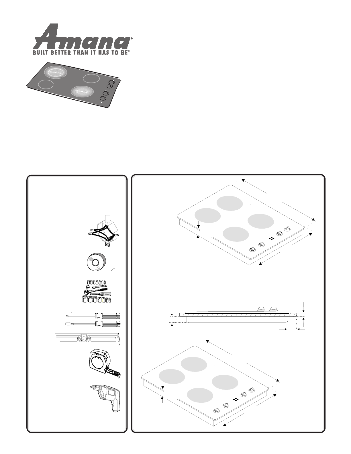
UNPACK
1
COOKTOP
3 1/8"
• Remove all packing and printed material
packed with the cooktop.
• Slide the cooktop out of the box.
• To avoid any damage, do not slide the
cooktop across a countertop.
2 7/8"
30-inch models
29 9/16"
21 1/2 "
1
/4"
1
/4"
Tape Measure
Drill and DrillBits
as needed
35 3/4"
36-inch models
3 1/8"
21 1/2 "
Page 2
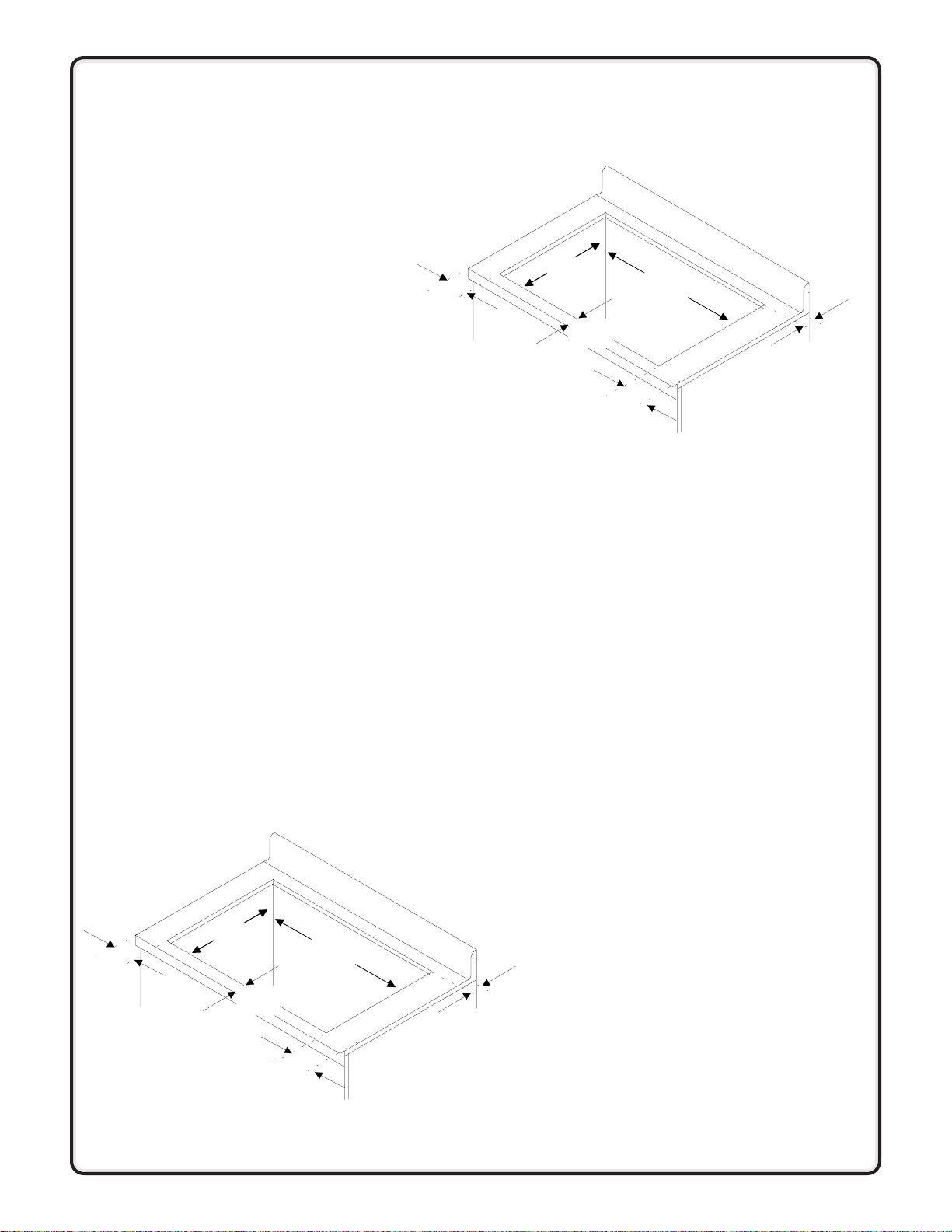
PREPARE
2
CUTOUT
Read through all instructions and
review both
to Combustible Surfaces
final cooktop clearances.
Cutout dimensions are calculated
to meet minimum clearance
requirements specified for
Minimum Clearances
section for
Minimum Clearances to
Combustible Surfaces
1
/2-inch differences between
Minimum Clearances and the
cutout are used by the frame
edge of the cooktop.
. The
Successful installation
In order to successfully install the AKT or AKH series
cooktops:
30-inch models
1
/2"
min
20
3/
2 1/2"
"
4
1
/2"
min
28
7/
"
8
1
/2"
min
1. Read all instructions thoroughly before beginning
installation project.
2. Prepare cutout according to cutout dimensions
provided.
3. Follow all safety guidelines provided.
4. Obey all local codes and ordinances for electrical
connections and power supply .
5. Contact Amana with any questions, concerns or
comments about the installation.
36-inch models
3/
20
"
1
/2"
min
4
2 1/2"
34 1/
"
8
1
/2"
min
Placing Cooktop on
Countertop
Cooktop can be installed with
glasstop resting on the countertop
or with the glasstop recessed into
the countertop.
If a recessed installation is desired,
a countertop inlay kit can be
purchased from an Amana dealer.
The following instructions are to
install the cooktop with the
glasstop resting on the
countertop.
Cooktop is not secured to
countertop—its weight keeps it in
place.
1
/2"
min
Page 3

CONNECT POWER
3
SUPPLY
Wire Connections
Cooktop has approximately 36 inches of flexible wire conduit
attached to bottom of cooktop. Approximately
6 inches of green or bare ground wire and 3 insulated wires:
black, red and white, extend beyond end of conduit. Conduit lies
directly below controls. If the cooktop is installed with the controls
on the left side, the conduit will be on the bottom left. If the
cooktop is installed with the controls on the right, the conduit will
be on the bottom right. Connect wire leads extending from conduit
to house wires inside junction box. Refer to local codes and
attach according to options. AKT models do not have a white
(neutral) wire.
Junction Box Location
For junction box location when installing over a wall oven, see
Installing Over a Wall Oven
in bottom of unit. Junction box must be located within 30 inches of
power supply entry point. Locate junction box within shaded area.
Junction box is not included with cooktop.
4-WIRE INSTALLATION 3-WIRE INSTALLATION
Unit wire House wi r e Unit wire House wi r e
120 VAC (red) 120 VAC (red) 120 VAC (red) 120 VAC (red)
120 VAC (black) 120 VAC (black) 120 VAC (black) 120 VAC (black)
Neutral (white) Neutral (white) Neutral (white) Neutral (white)
Ground
(green/bare)
section. Power supply enters cooktop
Ground (green) Ground
(green/bare)
9"
14 1/4"
C
L
Neutral (white)
6 1/4"
4-wire Electrical Installation
United States or Canada
Red House
Wire
Black
House Wir e
Red
Cooktop Wire
Black
Cooktop Wire
3-Wire Electrical Installation
United States Only
Red House
Wire
Green
House Wir e
White
House Wir e
White
Cooktop Wire
Green
Cooktop Wire
Black
House Wire
Red
Cooktop Wire
Black
Cooktop Wire
Cooktop Removal and Reinstallation
Specialty countertops and installations may make service,
removal and reinstallation difficult.
1. Turn off circuit breaker or electrical supply.
2. Disconnect cooktop wires from house wires. See Connect
Power Supply.
3. Lift cooktop out of cutout.
4. Reverse procedure to reinstall cooktop.
White
House Wire
White
Cooktop Wire
Green
Cooktop Wire
Page 4

!
!
IMPORTANT SAFETY INFORMATION
!
WARNING
To eliminate the risk of burns or fire by reaching over
heated surface elements, cabinet storage space
located above the surface elements should be
avoided. If cabinet storage is to be provided, the risk
can be reduced by installing a range hood that
projects horizontally a minimum of 5 inches beyond
the bottom of the cabinets.
CAUTION
Do not store items of interest to children in cabinets
above the cooktop or behind the cooktop. Children
climbing on cooktop to reach items could be seriously
injured.
To avoid risk of electrical shock, personal injury, or
death:
• disconnect cooktop from main power supply before
servicing.
• make sure cooktop has been properly grounded.
• if connecting copper leads to aluminum house
wiring, use only connectors designed for joining
copper to aluminum. Follow connector
manufacturer’s recommendations closely.
• do not ground through neutral wire if installed in
mobile home or if local codes do not permit
grounding through neutral wire.
WARNING
Minimum Clearances to Combustible Surfaces
Underwriter’s Laboratories, Inc. specifies this
cooktop can be installed as specified in the
following diagram. The dimensions provided
are to be measured from the cooktop itself,
and not the installation cutout for the cooktop.
A—30 inches minimum clearance between the
top of the cooking surface and the bottom of
an unprotected wood or metal cabinet.
OR
A—24 inches minimum clearance when bottom
of wood or metal cabinet is protected by not
less than 1/4-inch thick flame retardant
millboard covered with not less than No.28
MSG sheet steel, 0.015 inch thick stainless
steel, 0.024-inch thick aluminum, or 0.020
inch thick copper.
B—0 inches minimum distance between cooktop
and wall, cabinet taller than 36 inches or a
walkway .
C—0 inches minimum distance between cooktop
and back wall or backguard.
D—2 1/2 inches minimum distance between
cooktop and edge of countertop.
E—Minimum of 18 inches (on each side)
between top of countertop and bottom of an
unprotected wood or metal cabinet.
F—Minimum of 30 inches (30-inch cooktop)
length for protected cabinets above the
cooktop OR minimum of 36 inches for
36-inch cooktops (refer to letter A).
D
C
F
A
E
E
B
Part No. 36-31967701-0
Printed in U.S.A. 02/00
SAVE THESE INSTRUCTIONS
2000 Amana Appliances
Amana, Iowa 52204
Page 5

ü
Before You Install
Consider Description
Installation Requirements
Location
Electrical Requirements
To eliminate the risk of burns or fire by reaching over heated surface elements,
cabinet storage space located above the surface elements should be avoided. If
cabinet storage is to be provided, the risk can be reduced by installing a range
hood that projects horizontally a minimum of 5 inches beyond the bottom of the
cabinets.
Use dimensions shown in this manual to determine space needed for
installation.
Cooktop must not be installed or stored in an area where it will be exposed to
water and/or weather.
Specialty Countertop Materials
Refer to product information for instructions on handling specialty countertop
materials such as tile or ceramic. Countertop must be level for proper cooktop
installation.
Electrical Supply
Cooktop needs a 3 or 4 wire 240 Volt AC, 60 Hertz circuit protected by a
separate 30 amp circuit breaker or time delay fuse. Wiring system and grounding
must conform to the latest edition of the National Electric Code, ANSI/NFPA 70,
or the Canadian Electrical Code, CSA C22.1. Installation must conform to all
local, municipal and state building codes, and local utility regulations. Connect
cooktop to power supply with MAXIMUM RATED VOLTAGE listed on the rating
plate. Line voltage must not exceed rated voltage.
Copper Wire
Conduit is approved for copper wire connection only. If aluminum house wiring is
to be connected, use connectors designed for joining copper to aluminum and
follow the manufacturer’s recommended procedure closely. The following
procedure is suggested for splicing copper to aluminum wiring:
Splice copper wires to aluminum wiring using connectors that are certified
by Underwriter’s Laboratories and recognized for joining copper to
aluminum. Follow the connector manufacturer’s recommended procedure.
Wire used, location and enclosure of splices must conform to local codes.
Junction Box
Junction box is not supplied with cooktop. Junction box must be U.L. or C.S.A.
listed and meet NEC and Mobile Home Manufacturers Association Standards.
• Three-conductor junction box allowed for residential in U.S.
• Four-conductor junction box required in Canada and for most mobile home
installations but can be used for residential.
• Refer to local, municipal and state building codes.
NOTE:
A power cord must not be used.
Questions? See Owners Manual or
call Amana Consumer Affairs at 1-800-843-0304
Page 6

Installing over a wall oven
Cooktops may be installed over the Amana AOES3030
and the Amana AOCS3040 wall ovens only . The
following instructions are not for a recessed (inlaid)
cooktop installation over a wall oven. To ensure proper
installation and safety , these installation instructions must
be followed exactly .
• For a recessed or inlaid cooktop installation, use
the installation instructions provided in the Amana
Cooktop-Inlay Kit.
• All installations specified are for a 36" cabinet
height and a 23 1/2" minimum depth.
• Cooktop should be centered over the wall oven
using a center line.
• Refer to the wall oven installation instructions for
proper wall oven installation, or contact Amana
Consumer Affairs for the most current installation
instructions.
• Wall oven should lay flat against the bottom of the
cabinet.
minimum
1
4
/2"
Cooktop Clearance
To ensure proper clearance, there must be a
minimum of 4 1/2-inches between the top of the
countertop and the top of the wall oven cutout. This
measurement must not be taken at the top of the oven
or its frame. This clearance is required for proper
placement of the cooktop over the wall oven.
4 1/2"
6 1/4"
C
14 1/4"
L
24"
28 1/2"
27 1/4"
28 1/2"
Junction Box Location
Junction box location is indicated by the gray shaded
area.
• For wall oven wiring instructions, refer to wall
oven installation instructions.
• For cooktop wiring instructions, refer to
Connect Power Supply
instruction.
• Junction box must be located a minimum of
4 1/2 -inches from the top of the countertop.
• Junction box must be located a minimum of
24-inches from the bottom of the wall oven
cutout.
• Junction box must be UL or CSA listed.
section of this installation
 Loading...