

ALTUSEN PN7212, PN7320 User Manual

Power Over the NET™
PN7212 / PN7320
Power Distribution Unit
User Manual
www.aten.com
PN7212 / PN7320 User Manual
FCC Information
This is an FCC Class A product. In a domestic environment this product may
cause radio interference in which case the user may be required to take
adequate measures.
This equipment has been tested and found to comply with the limits for a Class
A digital device, pursuant to Part 15 of the FCC Rules. These limits are
designed to provide reasonable protection against harmful interference when
the equipment is operated in a commercial environment. This equipment
generates, uses and can radiate radio frequency energy and, if not installed and
used in accordance with the instruction manual, may cause harmful
interference to radio communications. Operation of this equipment in a
residential area is likely to cause harmful interference in which case the user
will be required to correct the interference at his own expense.
RoHS
This product is RoHS compliant.
SJ/T 11364-2006
The following contains information that relates to China.
ii
PN7212 / PN7320 User Manual
User Information
Online Registration
Be sure to register your product at our online support center:
International http://support.aten.com
North America http://www.aten-usa.com/product_registration
Telephone Support
For telephone support, call this number:
International 886-2-8692-6959
China 86-10-5255-0110
Japan 81-3-5615-5811
Korea 82-2-467-6789
North America 1-888-999-ATEN ext 4988
United Kingdom 44-8-4481-58923
User Notice
All information, documentation, and specifications contained in this manual are subject to change without
prior notification by the manufacturer. The manufacturer makes no representations or warranties, either
expressed or implied, with respect to the contents hereof and specifically disclaims any warranties as to
merchantability or fitness for any particular purpose. Any of the manufacturer's software described in this
manual is sold or licensed as is. Should the programs prove defective following their purchase, the buyer
(and not the manufacturer, its distributor, or its dealer), assumes the entire cost of all necessary servicing,
repair and any incidental or consequential damages resulting from any defect in the software.
The manufacturer of this system is not responsible for any radio and/or TV interference caused by
unauthorized modifications to this device. It is the responsibility of the user to correct such interference.
The manufacturer is not responsible for any damage incurred in the operation of this system if the correct
operational voltage setting was not selected prior to operation. PLEASE VERIFY THAT THE
VOLTAGE SETTING IS CORRECT BEFORE USE.
PN Device Safety Notice
Set the maximum permissible breaker protection in the building circuitry to the current rating
specified on the rating plate. Observe all national regulations and safety codes as well as
deviations for breakers.
Only connect the PN Device to a grounded power outlet or a grounded system!
Make sure that the total current input of the connected systems does not exceed the current
rating specified on the rating plate of the PN Device.
There is a risk of explosion if the battery is replaced with an incorrect type. Dispose of used
batteries according to the relevant instructions.
If the power source is unstable, the PN Device’s measurements will not be accurate.
iii

PN7212 / PN7320 User Manual
Copyright © 2004–2011 ATEN® International Co., Ltd.
Manual Part No. PAPE-0322-AX2G
Printing Date: 2011-07-07
ALTUSEN and the ALTUSEN logo are registered trademarks of ATEN International Co., Ltd. All rights re-
served. All other brand names and trademarks are the registered property of their respective owners.
Package Contents
The PN7212 / PN7320 package consists of:
1 PN7212 or PN7320 Power Distribution Unit
4 Serial Adapters:
1 SA0142 (RJ45F to DB9M)
1 SA0149 (RJ45F to DB9F)
1 SA0150 (RJ45F to DB9M)
1 SA0151 (RJ45F to DB9F)
2 Rack Mount Kits
1 Grounding Wire
1 User Manual*
1 Quick Start Guide
1 Software CD
Check to make sure that all of the components are present and in good order.
If anything is missing, or was damaged in shipping, contact your dealer.
Read this manual thoroughly and follow the installation and operation
procedures carefully to prevent any damage to the switch or to any other
devices on the PN7212 / PN7320 installation.
* Features may have been added to the PN7212 / PN7320 since this manual
was printed. Please visit our website to download the most up-to-date version
of the manual.
iv

PN7212 / PN7320 User Manual
Contents
FCC Information . . . . . . . . . . . . . . . . . . . . . . . . . . . . . . . . . . . . . . . . . . . . . ii
SJ/T 11364-2006. . . . . . . . . . . . . . . . . . . . . . . . . . . . . . . . . . . . . . . . . . . . . ii
User Information . . . . . . . . . . . . . . . . . . . . . . . . . . . . . . . . . . . . . . . . . . . . .iii
Online Registration . . . . . . . . . . . . . . . . . . . . . . . . . . . . . . . . . . . . . . . .iii
Telephone Support . . . . . . . . . . . . . . . . . . . . . . . . . . . . . . . . . . . . . . . .iii
User Notice . . . . . . . . . . . . . . . . . . . . . . . . . . . . . . . . . . . . . . . . . . . . . .iii
PN Device Safety Notice . . . . . . . . . . . . . . . . . . . . . . . . . . . . . . . . . . . .iii
Package Contents. . . . . . . . . . . . . . . . . . . . . . . . . . . . . . . . . . . . . . . . . . . iv
About This Manual . . . . . . . . . . . . . . . . . . . . . . . . . . . . . . . . . . . . . . . . . . . x
Overview . . . . . . . . . . . . . . . . . . . . . . . . . . . . . . . . . . . . . . . . . . . . . . . . x
Conventions . . . . . . . . . . . . . . . . . . . . . . . . . . . . . . . . . . . . . . . . . . . . xi
Product Information. . . . . . . . . . . . . . . . . . . . . . . . . . . . . . . . . . . . . . . . . . xii
Chapter 1.
Introduction
Overview . . . . . . . . . . . . . . . . . . . . . . . . . . . . . . . . . . . . . . . . . . . . . . . . . . .1
Features . . . . . . . . . . . . . . . . . . . . . . . . . . . . . . . . . . . . . . . . . . . . . . . . . . .2
Power Distribution . . . . . . . . . . . . . . . . . . . . . . . . . . . . . . . . . . . . . . . . . 2
Remote Access . . . . . . . . . . . . . . . . . . . . . . . . . . . . . . . . . . . . . . . . . . .2
Operation. . . . . . . . . . . . . . . . . . . . . . . . . . . . . . . . . . . . . . . . . . . . . . . .3
Management . . . . . . . . . . . . . . . . . . . . . . . . . . . . . . . . . . . . . . . . . . . . .4
Security . . . . . . . . . . . . . . . . . . . . . . . . . . . . . . . . . . . . . . . . . . . . . . . . .5
Requirements . . . . . . . . . . . . . . . . . . . . . . . . . . . . . . . . . . . . . . . . . . . . . . . 5
Components . . . . . . . . . . . . . . . . . . . . . . . . . . . . . . . . . . . . . . . . . . . . . . . . 6
Front View . . . . . . . . . . . . . . . . . . . . . . . . . . . . . . . . . . . . . . . . . . . . . . .6
Port and Led Panel . . . . . . . . . . . . . . . . . . . . . . . . . . . . . . . . . . . . . . . . 8
Chapter 2.
Hardware Setup
Before You Begin . . . . . . . . . . . . . . . . . . . . . . . . . . . . . . . . . . . . . . . . . . . 11
Rack Mounting . . . . . . . . . . . . . . . . . . . . . . . . . . . . . . . . . . . . . . . . . . . . . 11
Single Stage Installation . . . . . . . . . . . . . . . . . . . . . . . . . . . . . . . . . . . . . . 13
Daisy Chaining . . . . . . . . . . . . . . . . . . . . . . . . . . . . . . . . . . . . . . . . . . . . .15
Chapter 3.
Super Administrator Setup
First Time Setup . . . . . . . . . . . . . . . . . . . . . . . . . . . . . . . . . . . . . . . . . . . . 19
Network Configuration. . . . . . . . . . . . . . . . . . . . . . . . . . . . . . . . . . . . . 20
Changing the Administrator Login . . . . . . . . . . . . . . . . . . . . . . . . . . . .21
Moving On. . . . . . . . . . . . . . . . . . . . . . . . . . . . . . . . . . . . . . . . . . . . . . . . . 22
Chapter 4.
Browser Login
Logging In . . . . . . . . . . . . . . . . . . . . . . . . . . . . . . . . . . . . . . . . . . . . . . . . .23
The PN7212 / PN7320 Main Page . . . . . . . . . . . . . . . . . . . . . . . . . . . . . .24
Page Components . . . . . . . . . . . . . . . . . . . . . . . . . . . . . . . . . . . . . . . . . .25
v

PN7212 / PN7320 User Manual
Chapter 5.
Outlet Access
Overview. . . . . . . . . . . . . . . . . . . . . . . . . . . . . . . . . . . . . . . . . . . . . . . . . . 27
The Outlet Selection Sidebar . . . . . . . . . . . . . . . . . . . . . . . . . . . . . . . . . . 28
Manual Power Management . . . . . . . . . . . . . . . . . . . . . . . . . . . . . . . . 29
Connections . . . . . . . . . . . . . . . . . . . . . . . . . . . . . . . . . . . . . . . . . . . . . . . 31
Station Level . . . . . . . . . . . . . . . . . . . . . . . . . . . . . . . . . . . . . . . . . . . . 31
Outlet Level. . . . . . . . . . . . . . . . . . . . . . . . . . . . . . . . . . . . . . . . . . . . . 33
Outlet Group Level . . . . . . . . . . . . . . . . . . . . . . . . . . . . . . . . . . . . . . . 35
User Preferences . . . . . . . . . . . . . . . . . . . . . . . . . . . . . . . . . . . . . . . . . . . 36
Sessions . . . . . . . . . . . . . . . . . . . . . . . . . . . . . . . . . . . . . . . . . . . . . . . . . . 37
Access . . . . . . . . . . . . . . . . . . . . . . . . . . . . . . . . . . . . . . . . . . . . . . . . . . . 37
Station Level . . . . . . . . . . . . . . . . . . . . . . . . . . . . . . . . . . . . . . . . . . . . 37
Outlet Level. . . . . . . . . . . . . . . . . . . . . . . . . . . . . . . . . . . . . . . . . . . . . 38
Configuration . . . . . . . . . . . . . . . . . . . . . . . . . . . . . . . . . . . . . . . . . . . . . . 39
Station Level Configuration. . . . . . . . . . . . . . . . . . . . . . . . . . . . . . . . . 39
Outlet Level Configuration. . . . . . . . . . . . . . . . . . . . . . . . . . . . . . . . . . 43
Chapter 6.
User Management
Overview. . . . . . . . . . . . . . . . . . . . . . . . . . . . . . . . . . . . . . . . . . . . . . . . . . 49
Users . . . . . . . . . . . . . . . . . . . . . . . . . . . . . . . . . . . . . . . . . . . . . . . . . . . . 50
Adding Users. . . . . . . . . . . . . . . . . . . . . . . . . . . . . . . . . . . . . . . . . . . . 50
Modifying User Accounts . . . . . . . . . . . . . . . . . . . . . . . . . . . . . . . . . . 53
Deleting User Accounts. . . . . . . . . . . . . . . . . . . . . . . . . . . . . . . . . . . . 53
Moving On. . . . . . . . . . . . . . . . . . . . . . . . . . . . . . . . . . . . . . . . . . . . . . 53
Groups . . . . . . . . . . . . . . . . . . . . . . . . . . . . . . . . . . . . . . . . . . . . . . . . . . . 54
Creating Groups . . . . . . . . . . . . . . . . . . . . . . . . . . . . . . . . . . . . . . . . . 54
Modifying Groups . . . . . . . . . . . . . . . . . . . . . . . . . . . . . . . . . . . . . . . . 56
Deleting Groups . . . . . . . . . . . . . . . . . . . . . . . . . . . . . . . . . . . . . . . . . 56
Users and Groups. . . . . . . . . . . . . . . . . . . . . . . . . . . . . . . . . . . . . . . . . . . 57
Assigning Users to a Group From the Accounts Page . . . . . . . . . . . . 57
Removing Users From a Group From the Accounts Page . . . . . . . . . 58
Assigning Users to a Group From the Groups Page. . . . . . . . . . . . . . 59
Removing Users From a Group From the Groups Page. . . . . . . . . . . 60
Device Assignment . . . . . . . . . . . . . . . . . . . . . . . . . . . . . . . . . . . . . . . . . . 61
Assigning Device Permissions From the Accounts Menu. . . . . . . . . . 61
Assigning Device Permissions From the Groups Page . . . . . . . . . . . 62
Chapter 7.
Device Management
Overview. . . . . . . . . . . . . . . . . . . . . . . . . . . . . . . . . . . . . . . . . . . . . . . . . . 63
Device Information . . . . . . . . . . . . . . . . . . . . . . . . . . . . . . . . . . . . . . . . . . 63
Network. . . . . . . . . . . . . . . . . . . . . . . . . . . . . . . . . . . . . . . . . . . . . . . . . . . 65
Service Ports. . . . . . . . . . . . . . . . . . . . . . . . . . . . . . . . . . . . . . . . . . . . 65
Settings . . . . . . . . . . . . . . . . . . . . . . . . . . . . . . . . . . . . . . . . . . . . . . . . 66
IP Installer . . . . . . . . . . . . . . . . . . . . . . . . . . . . . . . . . . . . . . . . . . . . . . 66
vi

PN7212 / PN7320 User Manual
IPv4 Configuration. . . . . . . . . . . . . . . . . . . . . . . . . . . . . . . . . . . . . . . .67
IPv6 Configuration. . . . . . . . . . . . . . . . . . . . . . . . . . . . . . . . . . . . . . . .68
ANMS . . . . . . . . . . . . . . . . . . . . . . . . . . . . . . . . . . . . . . . . . . . . . . . . . . . .69
Event Notification . . . . . . . . . . . . . . . . . . . . . . . . . . . . . . . . . . . . . . . .69
Authentication & Authorization . . . . . . . . . . . . . . . . . . . . . . . . . . . . . .73
CC Management . . . . . . . . . . . . . . . . . . . . . . . . . . . . . . . . . . . . . . . . .77
OOBC . . . . . . . . . . . . . . . . . . . . . . . . . . . . . . . . . . . . . . . . . . . . . . . . . . . . 78
Console Port Settings . . . . . . . . . . . . . . . . . . . . . . . . . . . . . . . . . . . . .78
Modem Settings . . . . . . . . . . . . . . . . . . . . . . . . . . . . . . . . . . . . . . . . .79
Security . . . . . . . . . . . . . . . . . . . . . . . . . . . . . . . . . . . . . . . . . . . . . . . . . . . 84
Login String . . . . . . . . . . . . . . . . . . . . . . . . . . . . . . . . . . . . . . . . . . . . .85
IP and MAC Filtering . . . . . . . . . . . . . . . . . . . . . . . . . . . . . . . . . . . . . . 85
Account Policy. . . . . . . . . . . . . . . . . . . . . . . . . . . . . . . . . . . . . . . . . . .87
Private Certificate . . . . . . . . . . . . . . . . . . . . . . . . . . . . . . . . . . . . . . . .88
Customization . . . . . . . . . . . . . . . . . . . . . . . . . . . . . . . . . . . . . . . . . . . . . .89
Login Failures . . . . . . . . . . . . . . . . . . . . . . . . . . . . . . . . . . . . . . . . . . .89
Working Mode . . . . . . . . . . . . . . . . . . . . . . . . . . . . . . . . . . . . . . . . . . .89
Date/Time . . . . . . . . . . . . . . . . . . . . . . . . . . . . . . . . . . . . . . . . . . . . . . . . . 90
Time Zone . . . . . . . . . . . . . . . . . . . . . . . . . . . . . . . . . . . . . . . . . . . . . .90
Manual Input . . . . . . . . . . . . . . . . . . . . . . . . . . . . . . . . . . . . . . . . . . . .91
Network Time . . . . . . . . . . . . . . . . . . . . . . . . . . . . . . . . . . . . . . . . . . .91
Finishing Up . . . . . . . . . . . . . . . . . . . . . . . . . . . . . . . . . . . . . . . . . . . .91
Chapter 8.
Log
Overview . . . . . . . . . . . . . . . . . . . . . . . . . . . . . . . . . . . . . . . . . . . . . . . . . .93
System Log . . . . . . . . . . . . . . . . . . . . . . . . . . . . . . . . . . . . . . . . . . . . . . . .93
The Log Event List . . . . . . . . . . . . . . . . . . . . . . . . . . . . . . . . . . . . . . .94
Search . . . . . . . . . . . . . . . . . . . . . . . . . . . . . . . . . . . . . . . . . . . . . . . . . 95
Save . . . . . . . . . . . . . . . . . . . . . . . . . . . . . . . . . . . . . . . . . . . . . . . . . . 96
Notification Settings . . . . . . . . . . . . . . . . . . . . . . . . . . . . . . . . . . . . . . . . .97
Chapter 9.
Maintenance and Download
Overview . . . . . . . . . . . . . . . . . . . . . . . . . . . . . . . . . . . . . . . . . . . . . . . . . .99
Maintenance . . . . . . . . . . . . . . . . . . . . . . . . . . . . . . . . . . . . . . . . . . . . . . .99
Firmware Upgrade. . . . . . . . . . . . . . . . . . . . . . . . . . . . . . . . . . . . . . . .99
Backup/Restore. . . . . . . . . . . . . . . . . . . . . . . . . . . . . . . . . . . . . . . . .101
Download . . . . . . . . . . . . . . . . . . . . . . . . . . . . . . . . . . . . . . . . . . . . . . . .103
Chapter 10.
The Log Server
Installation. . . . . . . . . . . . . . . . . . . . . . . . . . . . . . . . . . . . . . . . . . . . . . . .105
Starting Up . . . . . . . . . . . . . . . . . . . . . . . . . . . . . . . . . . . . . . . . . . . . . . .106
The Menu Bar . . . . . . . . . . . . . . . . . . . . . . . . . . . . . . . . . . . . . . . . . . . . .107
Configure. . . . . . . . . . . . . . . . . . . . . . . . . . . . . . . . . . . . . . . . . . . . . .107
Events . . . . . . . . . . . . . . . . . . . . . . . . . . . . . . . . . . . . . . . . . . . . . . . . 108
vii

PN7212 / PN7320 User Manual
Options . . . . . . . . . . . . . . . . . . . . . . . . . . . . . . . . . . . . . . . . . . . . . . . 110
Help. . . . . . . . . . . . . . . . . . . . . . . . . . . . . . . . . . . . . . . . . . . . . . . . . . 110
The Log Server Main Screen . . . . . . . . . . . . . . . . . . . . . . . . . . . . . . . . . 111
Overview . . . . . . . . . . . . . . . . . . . . . . . . . . . . . . . . . . . . . . . . . . . . . . 111
The List Panel . . . . . . . . . . . . . . . . . . . . . . . . . . . . . . . . . . . . . . . . . . 112
The Event Panel . . . . . . . . . . . . . . . . . . . . . . . . . . . . . . . . . . . . . . . . 112
Chapter 11.
Out of Band Operation
Overview. . . . . . . . . . . . . . . . . . . . . . . . . . . . . . . . . . . . . . . . . . . . . . . . . 113
Console Terminal Session . . . . . . . . . . . . . . . . . . . . . . . . . . . . . . . . . . . 113
Logging In . . . . . . . . . . . . . . . . . . . . . . . . . . . . . . . . . . . . . . . . . . . . . 116
Modem Session . . . . . . . . . . . . . . . . . . . . . . . . . . . . . . . . . . . . . . . . . . . 117
Connection Setup . . . . . . . . . . . . . . . . . . . . . . . . . . . . . . . . . . . . . . . 117
Finishing Up . . . . . . . . . . . . . . . . . . . . . . . . . . . . . . . . . . . . . . . . . . . 121
Logging In . . . . . . . . . . . . . . . . . . . . . . . . . . . . . . . . . . . . . . . . . . . . . 122
Chapter 12.
Remote Terminal Operation
Overview. . . . . . . . . . . . . . . . . . . . . . . . . . . . . . . . . . . . . . . . . . . . . . . . . 123
Telnet . . . . . . . . . . . . . . . . . . . . . . . . . . . . . . . . . . . . . . . . . . . . . . . . . . . 123
Logging In . . . . . . . . . . . . . . . . . . . . . . . . . . . . . . . . . . . . . . . . . . . . . 123
SSH . . . . . . . . . . . . . . . . . . . . . . . . . . . . . . . . . . . . . . . . . . . . . . . . . . . . 125
Terminal Session (Linux): . . . . . . . . . . . . . . . . . . . . . . . . . . . . . . . . . 125
Third Party Utility (Windows): . . . . . . . . . . . . . . . . . . . . . . . . . . . . . . 126
Chapter 13.
LDAP Server Configuration
Introduction . . . . . . . . . . . . . . . . . . . . . . . . . . . . . . . . . . . . . . . . . . . . . . . 127
Install the Windows 2003 Support Tools . . . . . . . . . . . . . . . . . . . . . . . . 127
Install the Active Directory Schema Snap-in. . . . . . . . . . . . . . . . . . . . . . 128
Create a Start Menu Shortcut Entry . . . . . . . . . . . . . . . . . . . . . . . . . . . . 128
Extend and Update the Active Directory Schema. . . . . . . . . . . . . . . . . . 129
Creating a New Attribute. . . . . . . . . . . . . . . . . . . . . . . . . . . . . . . . . . 129
Extending the Object Class With the New Attribute . . . . . . . . . . . . . 131
Editing Active Directory Users. . . . . . . . . . . . . . . . . . . . . . . . . . . . . . 133
OpenLDAP . . . . . . . . . . . . . . . . . . . . . . . . . . . . . . . . . . . . . . . . . . . . . . . 136
OpenLDAP Server Installation . . . . . . . . . . . . . . . . . . . . . . . . . . . . . 136
OpenLDAP Server Configuration . . . . . . . . . . . . . . . . . . . . . . . . . . . 137
Starting the OpenLDAP Server. . . . . . . . . . . . . . . . . . . . . . . . . . . . . 138
Customizing the OpenLDAP Schema. . . . . . . . . . . . . . . . . . . . . . . . 139
LDAP DIT Design and LDIF File . . . . . . . . . . . . . . . . . . . . . . . . . . . . 140
Using the New Schema. . . . . . . . . . . . . . . . . . . . . . . . . . . . . . . . . . . 142
viii

PN7212 / PN7320 User Manual
Appendix
Safety Instructions. . . . . . . . . . . . . . . . . . . . . . . . . . . . . . . . . . . . . . . . . .143
General . . . . . . . . . . . . . . . . . . . . . . . . . . . . . . . . . . . . . . . . . . . . . . .143
Rack Mounting . . . . . . . . . . . . . . . . . . . . . . . . . . . . . . . . . . . . . . . . .145
Technical Support . . . . . . . . . . . . . . . . . . . . . . . . . . . . . . . . . . . . . . . . . .146
International. . . . . . . . . . . . . . . . . . . . . . . . . . . . . . . . . . . . . . . . . . . .146
North America . . . . . . . . . . . . . . . . . . . . . . . . . . . . . . . . . . . . . . . . . .146
IP Address Determination . . . . . . . . . . . . . . . . . . . . . . . . . . . . . . . . . . . . 147
Trusted Certificates. . . . . . . . . . . . . . . . . . . . . . . . . . . . . . . . . . . . . . . . .149
Overview . . . . . . . . . . . . . . . . . . . . . . . . . . . . . . . . . . . . . . . . . . . . . .149
Installing the Certificate . . . . . . . . . . . . . . . . . . . . . . . . . . . . . . . . . . . 150
Certificate Trusted . . . . . . . . . . . . . . . . . . . . . . . . . . . . . . . . . . . . . . .151
Self-Signed Private Certificates . . . . . . . . . . . . . . . . . . . . . . . . . . . . . . . 153
Examples. . . . . . . . . . . . . . . . . . . . . . . . . . . . . . . . . . . . . . . . . . . . . . 153
Importing the Files. . . . . . . . . . . . . . . . . . . . . . . . . . . . . . . . . . . . . . .153
Troubleshooting . . . . . . . . . . . . . . . . . . . . . . . . . . . . . . . . . . . . . . . . . . .154
Overview . . . . . . . . . . . . . . . . . . . . . . . . . . . . . . . . . . . . . . . . . . . . . .154
Administrator Login Failure . . . . . . . . . . . . . . . . . . . . . . . . . . . . . . . . . . . 158
Specifications . . . . . . . . . . . . . . . . . . . . . . . . . . . . . . . . . . . . . . . . . . . . .159
Sensor Specifications . . . . . . . . . . . . . . . . . . . . . . . . . . . . . . . . . . . .160
Null Modem Cable Diagrams . . . . . . . . . . . . . . . . . . . . . . . . . . . . . . . . . 161
Limited Warranty . . . . . . . . . . . . . . . . . . . . . . . . . . . . . . . . . . . . . . . . . . .162
ix

PN7212 / PN7320 User Manual
About This Manual
This User Manual is provided to help you get the most from your PN7212 /
PN7320 system. It covers all aspects of installation, configuration and
operation. An overview of the information found in the manual is provided
below. Chapters 1, 4, and 5 are for all users. The remaining chapters are for
administrators and users with administrator privileges.
Overview
Chapter 1, Introduction, introduces you to the PN7212 / PN7320 system. Its
purpose, features and benefits are presented, and its front and back panel
components are described.
Chapter 2, Hardware Setup, provides step-by-step instructions for setting
up your installation.
Chapter 3, Super Administrator Setup, explains the procedures that the
super administrator employs to set up the PN7212 / PN7320 network
environment, and change the default username and password.
Chapter 4, Browser Login, describes how to log in to the PN7212 / PN7320
with an internet browser, and explains the layout and components of the
PN7212 / PN7320’s user interface.
Chapter 5, Outlet Access, describes the Outlet Access page; how to
configure the options it provides regarding outlet operation; and how to access
and operate the PN7212 / PN7320’s outlets.
Chapter 6, User Management, shows administrators how to create,
modify, and delete users and groups, and authorize outlet access for them.
Chapter 7, Device Management, shows administrators, and users with
device management permission how to configure and control overall Power
Over the NET™ device operations.
Chapter 8, Log, explains how to use the PN7212 / PN7320’s log feature to
view the events that take place on the Power Over the NET™ installation.
Chapter 9, Maintenance and Download, describes the procedures for
upgrading the PN7212 / PN7320’s firmware; backing up and restoring the
device’s configuration settings; and downloading a stand-alone Java Client AP
program to access the PN7212 / PN7320.
Chapter 10, The Log Server, explains how to install and configure the Log
Server.
x

PN7212 / PN7320 User Manual
Chapter 11, Out of Band Operation, explains alternative methods to
access the PN7212 / PN7320 in case the LAN that it resides on goes down, or
it cannot be accessed with the usual browser based method for some reason.
Chapter 12, Remote Terminal Operation, describes how the PN7212 /
PN7320 can be accessed via remote terminal sessions such as Telnet, SSH, and
PuTTY.
Chapter 13, LDAP Server Configuration, explains how to configure the
PN7212 / PN7320 for LDAP / LDAPS authentication and authorization with
Active Directory or OpenLDAP.
An Appendix, provides specifications and other technical information
regarding the PN7212 / PN7320.
Conventions
This manual uses the following conventions:
Monospaced Indicates text that you should key in.
[ ] Indicates keys you should press. For example, [Enter] means
to press the Enter key. If keys need to be chorded, they
appear together in the same bracket with a plus sign
between them: [Ctrl+Alt].
1. Numbered lists represent procedures with sequential steps.
♦ Bullet lists provide information, but do not involve sequential
steps.
→ Indicates selecting the option (on a menu or dialog box, for
example), that comes next. For example, Start
means to open the Start menu, and then select Run.
Indicates critical information.
→ Run
xi

PN7212 / PN7320 User Manual
Product Information
For information about all ALTUSEN products and how they can help you
connect without limits, visit ALTUSEN on the Web or contact an ALTUSEN
Authorized Reseller. Visit ALTUSEN on the Web for a list of locations and
telephone numbers
International http://www.aten.com
North America http://www.aten-usa.com
xii

Chapter 1
Introduction
Overview
The PN7212 and PN7320 are power distribution units (PDUs) that contain 12
and 20 AC outlets, respectively, and are available in IEC or NEMA socket
configurations. They provide secure, centralized, intelligent, power
management (power on, off, cycle) of remote data center equipment (servers,
KVM switches, network devices, serial data devices, etc.), as well as the ability
to monitor the center's health environment. By daisy chaining up to 15
additional PN7212 or PN7320 units, as many as 320 outlets can be managed
from a single interface.
The characteristics of each model are shown in the following table:
Model Amps Outlets
PN7212 16/20 12
PN7320 32/30 20
The power status of each outlet can be set individually, allowing users to
establish on/off schedules for each device. Outlets can also be aggregated into
groups, allowing groups of devices to be power managed at the same time,
while On/Off sequencing enables users to set the power on sequence and delay
time for each port to allow equipment to be turned on in the proper order.
Installation and operation is fast and easy: plugging cables into their
appropriate ports and user-friendly browser-based configuration and
management is all that is entailed. Serial access via modem, Telnet and SSH is
also supported to ensure system availability.
Since the PN7212 / PN7320' firmware is upgradeable over the Net, you can
stay current with the latest functionality improvements simply by downloading
updates from our website as they become available.
With its advanced security features and ease of operation, the PN7212 /
PN7320 is the most convenient, most reliable, and most cost effective way to
remotely manage power access for multiple computer installations.
1

PN7212 / PN7320 User Manual
Features
Power Distribution
Maximum Amps/Outlet:
NEMA: 20A / 12 outlets (PN7212); 30A / 20 outlets (PN7320)
IEC: 16A / 12 outlets (PN7212); 32A / 20 outlets (PN7320)
Space saving 0U rack mount design
IEC or NEMA outlet models
Daisy chain up to 15 additional stations for up to 192 (PN7212) or 320
(PN7320) outlets
A 2 x 7 segment front panel LED to indicate the currently selected Station
or Outlet.
A 3 x 7 segment front panel LED that can indicate the Current, Voltage,
Active Power, Sensor 1, and Sensor 2 status.
Overcurrent protection and recovery (PN7320 only)
Remote users can monitor outlet status via web pages on their browsers
Safe shutdown support
Separate power for the unit's own power and its power outlets. The user
interface is still accessible even when an overload condition trips the
devices' circuit breaker (PN7320 only)
Remote Access
Remote power control via TCP/IP and a built in 10/100 Ethernet port
Out of Band operation via modem access*
Network Interfaces: TCP/IP, PPP, UDP, HTTP, HTTPS, SSL, SMTP,
DHCP, ARP, NTP, DNS, Telnet, 10Base-T/100Base-TX, auto sense, Ping
IPv6 support
2

Chapter 1. Introduction
Operation
Local and Remote power outlet control (On, Off, Power Cycle) by
individual outlets and outlet groups
Outlet group support at the PDU and Daisy-chain levels – the same action
can be performed on a specified group of outlets at the same time
Supports redundant power management via daisy chaining and outlet
groups
On/Off scheduling for individual outlets and outlet groups. Power
management tasks can be scheduled to perform everything on a daily,
weekly, monthly, or user-specified times basis
Supports multiple power on/off control methods – Wake on LAN, System
After AC Back, Kill the Power
Power-on sequencing - users can set the power on sequence and delay time
for each port to allow equipment to be turned on in the proper order
Easy setup and operation via a browser-based user interface
Multibrowser support (IE, Mozilla, Firefox, Chrome, Safari, Opera,
Netscape)
Telnet and SSH access for text menu configuration and outlet level
switching / monitoring
Local console access support
Java GUI AP program provided for non-browser connectivity
RTC support to keep the timer running during times of no power.
Up to 64 user accounts - up to 32 concurrent logins
3

PN7212 / PN7320 User Manual
Management
Power status measurement at both the PDU and outlet levels
LED indicators for current, voltage and active power at the PDU level
Real-time current, voltage, active power, and power dissipation displayed
in a browsed-based UI for monitoring at the PDU and daisy-chained PDU
levels
Environment monitoring – supports external temperature and humidity
sensors for rack temperature and humidity monitoring
Current, voltage, active power, and power dissipation threshold setting
Alert notification for selected events (On, Off, Recycle, Failure, exceeding
threshold settings, etc.), via audio alarm and blinking LEDs (locally),
SMTP, SNMP trap notification, and digital output
Naming support for outlets and outlet groups
User outlet access assignment on an outlet-by-outlet basis.
Windows-based Log Server; event logging, KVM logging, and syslog
support
Integration with ALTUSEN CC2000 Management software
API for 3rd party software centralized control integration
Upgradeable firmware – daisy chained stations receive the upgrade via the
daisy chain bus
Multilanguage support: English, German, Traditional Chinese, Simplified
Chinese, Japanese, Korean, Russian
4

Chapter 1. Introduction
Security
Three-level password security
IP/MAC filtering
Strong security features include strong password protection and advanced
encryption technologies – 128 bit SSL
Remote authentication support: RADIUS, TACACS+, LDAP, LDAPS and
Active Directory
Requirements
Browsers accessing the PN7212 / PN7320 must support SSL 128 bit
encryption.
For cold booting of attached computers, the computer's BIOS must
support Wake on LAN or System after AC Back.
For Safe Shutdown:
The computer must be running Windows (Windows 2000 or higher), or
Linux.
The Safe Shutdown program (available by download from our
website), must be installed and running on the computer.
5
PN7212 / PN7320 User Manual
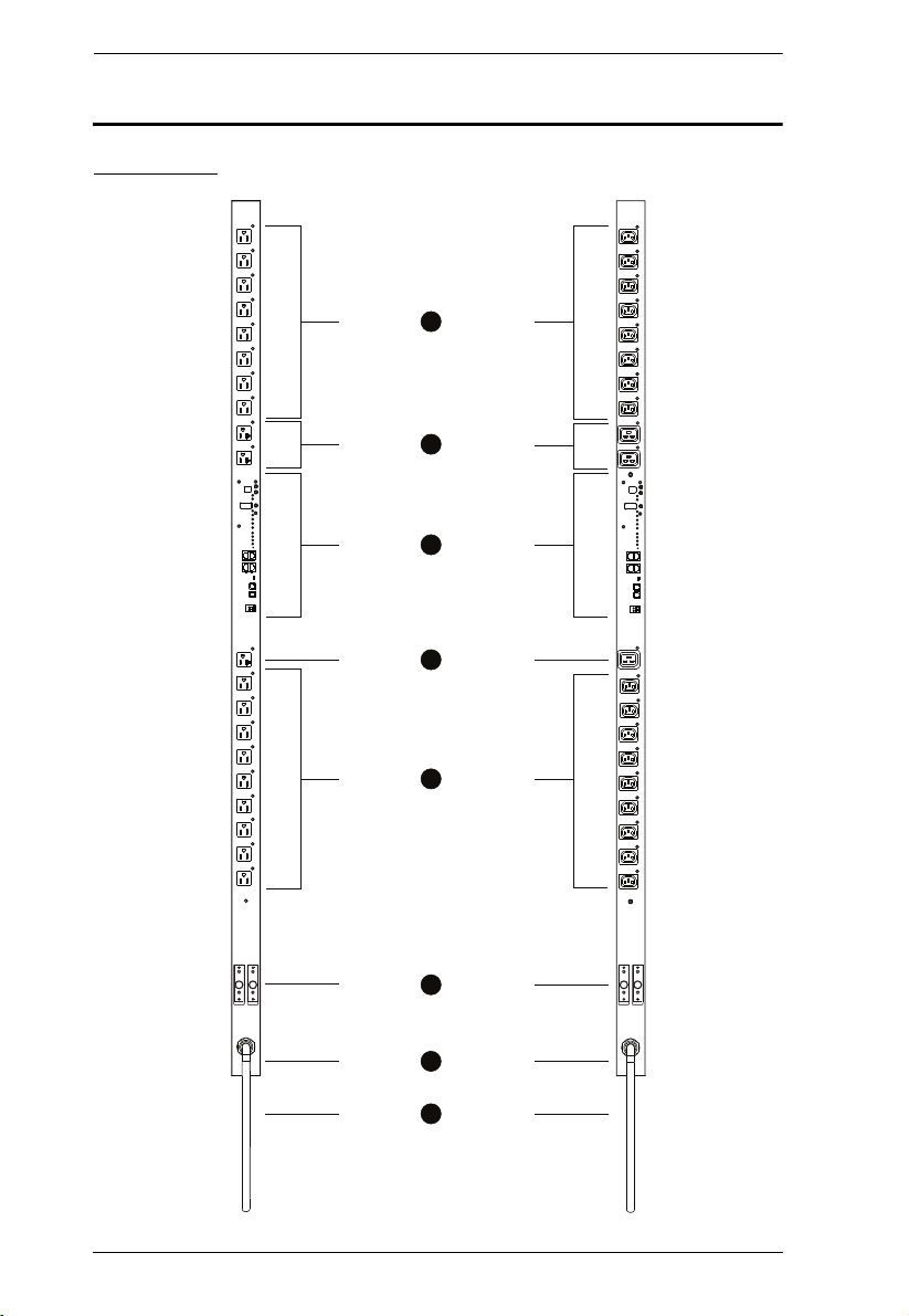
PN7320 - NEMA PN7320 - IEC
1
2
1
3
3
4
6
5
Components
Front View
6

No. Item Description
1 Power Sockets NEMA 5-15R
2 Port and LED
Panel
3 Power Sockets NEMA 5-20R
4 Circuit Breakers
(PN7320 Only)
5 Grounding
Terminal
6 Power Cord Plug the cord into your AC source.
– or –
IEC320 C13
Details of this section are provided below and on the
following page.
– or –
IEC320 C19
As a safety measure, if there is an overcurrent situation
regarding the device’s power, the circuit breakers will trip.
Press the button to recover normal operation.
Note: Circuit breakers are not provided on the PN7212.
Therefore, we strongly recommend that you do not plug the
unit directly into any unprotected power source (such as a
wall outlet).
The wire used to ground the unit connects here.
Note: The grounding terminal does not appear in the
diagram. It is hidden by the power cord.
Chapter 1. Introduction
Note: The Front View diagram depicts a PN7320. The PN7212 is basically the
same, except there are only 12 AC power sockets (6 on each side of the
Port and LED panel), and all the sockets are NEMA 5-15R or IEC320
C13. There are no NEMA 5-20R or IEC320 C19 sockets.
7
PN7212 / PN7320 User Manual
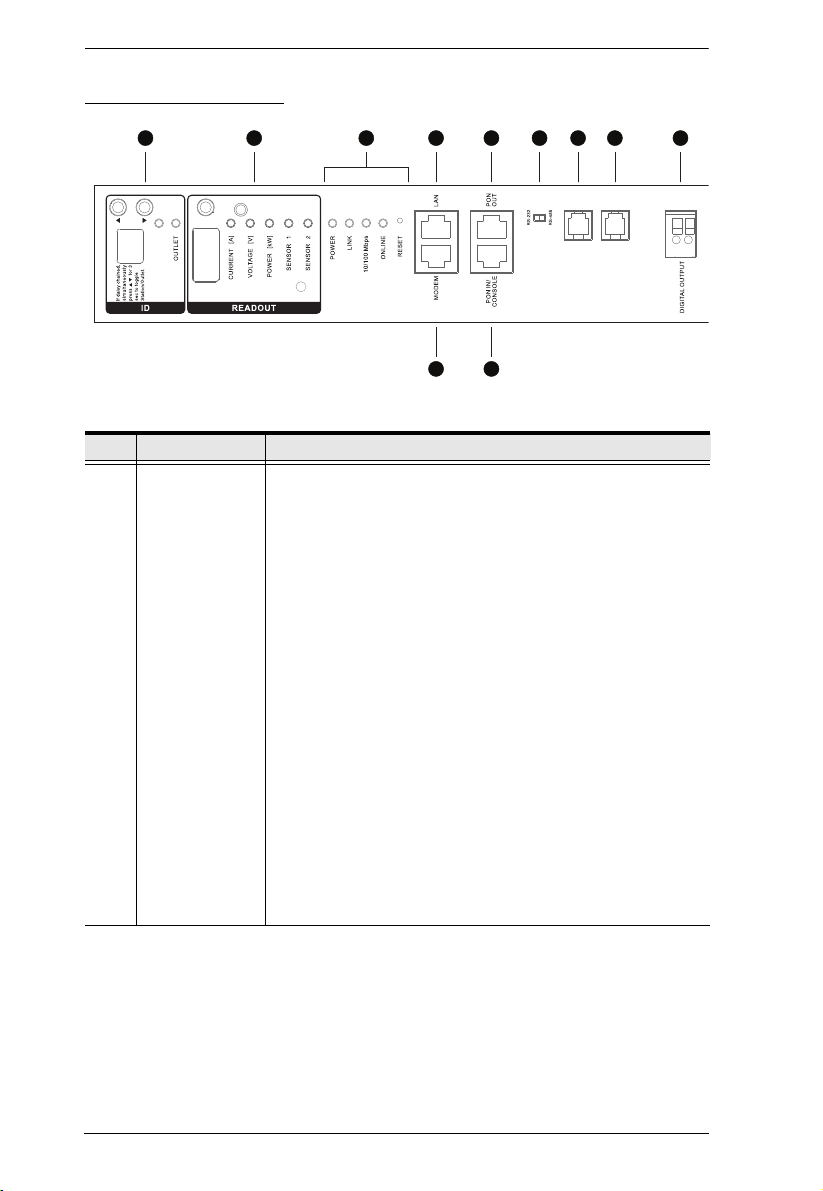
1 2 3 4 5 6 7 8 9
10 11
SENSOR 2
SENSOR 1
STATION
Port and Led Panel
No. Item Description
1 Station / Outlet
Selection
The Station / Outlet number appears in the display window.
The two small LEDs indicate whether it is Station number
or Outlet number that is displayed. The default is for the
Station number to be displayed
In a single stage installation, if Station is the selected
mode, pressing the Left or Right button changes to Outlet
mode.In Outlet mode, pressing the Left or Right button
moves you to the previous or next outlet.
In a daisy chained installation, pressing and holding both
buttons for 3 seconds toggles the selection between
Stations and Outlets.
If Station mode is selected, pressing the Left or Right
button moves you to the previous or next station in the
daisy chain.
If Outlet mode is selected pressing the Left or Right
button moves you to the previous or next outlet on the
current station.
To switch from the current outlet to an outlet on another
station, you must first toggle back to Station mode;
then move to the desired station; toggle back again to
Outlet mode; and move to the desired outlet.
8

Chapter 1. Introduction
No. Item Description
2 Readout
Section
The readouts for Current, Voltage, Active Power, Sensor 1,
and Sensor 2 appear in the display window.
The LEDs above the items indicate which one the readout
relates to.
Press the button above the display window to cycle the
selection among the items.
The Sensor 1 and Sensor 2 LEDs correspond to the
sensors plugged into the Sensor 1 and Sensor 2 ports. The
readout will reflect the type of sensor in the port
(Temperature or Humidity).
Note: If a combo sensor is used the display will switch
back and forth between showing a T and the temperature
readout for 5 seconds, and an H and the humidity readout
for 5 seconds.
3Status LEDs
and Reset
Switch
Power: Lights when the PN7212 / PN7320 is powered up
and ready to operate.
Link: Lights GREEN to indicate that a connection via the
PN7212 / PN7320's RJ-45 Ethernet port has been
established. Flashes to indicate that data is being
transmitted.
10/100 Mbps: Lights ORANGE to indicate 10 Mbps data
transmission speed. The LED lights GREEN to indicate 100
Mbps data transmission speed.
On Line: Lights to indicate that a connection to a KVM switch
or a parent PDU has been established. Flashes to indicate
that data is being transmitted.
Reset Switch: This switch is recessed and must be pushed
with a thin object, such as the end of a paper clip, or a
ballpoint pen.
Press and release to reboot the device.
Press and hold for more that three seconds to reset the
PN7212 / PN7320 to its factory default settings (except
for user account settings – they are not removed).
Press and hold and power on the device to return to
the factory installed firmware level (for firmware
upgrade failure recovery).
4 LAN Port The cable that connects the PN7212 / PN7320 to the
5 PON Out Port When daisy chaining PDUs, the cable that connects to the
Internet, LAN, or WAN plugs in here.
child device plugs in here.
If the child device is a PN0108, you must use an SA0150
adapter to plug into the PN0108’s PON In port (see PN7212 /
PN7320 to PN0108, page 17, for details).
9

PN7212 / PN7320 User Manual
No. Item Description
6 RS-232/RS-485
Switch
Selects which protocol the PON In / Console port uses.
For PON In use, select RS-232 (for PN0108) or RS-485
For Console use, select RS-232
For KVM switches, select either RS-232 (can be used for
shorter distances), or RS-485 (for longer distances).
When daisy chaining PN7212 / PN7320 devices, set the
switch to RS-232 on all child devices.
7 Sensor 1 A temperature or humidity sensor can plug in here.
8 Sensor 2 A temperature or humidity sensor can plug in here.
9 Digital Output A two pin terminal to attach a digital output device. For
10 Modem Port This port can be used for OOB dial in/dial back connection if
11 PON In /
Console Port
example, when a specified event is triggered, a GSM
message can be sent through this device to a mobile phone.
the device becomes unavailable over the network. An
SA0142 (DCE) adapter is required for this connection (see
Modem Session, page 117, for details).
This is a multifunction port:
PON In:
When used as a PON In port, it can: 1) Daisy chain the
device to a parent PDU; or 2) Connect the device to a
KVM switch.
If the parent PDU is a PN0108, you must use an SA0149
adapter to plug into the PN0108’s PON Out port (see
PN0108 to PN7212 / PN7320, page 18, for details).
Console:
When used as a Console port, it can establish a serial
terminal connection to a computer. An SA0151 (DTE)
adapter is required for this connection (see , page 11, for
details).
10
Chapter 2
1. Important safety information regarding the placement of this
device is provided on page 143. Please review it before
proceeding.
2. The PN7212 requires a dedicated circuit. See PN Device Safety
Notice, page iii, for important details.
3. Make sure that power to all the devices you will be connecting
up have been turned off. You must unplug the power cords of
any computers that have the Keyboard Power On function.
Hardware Setup
Before You Begin
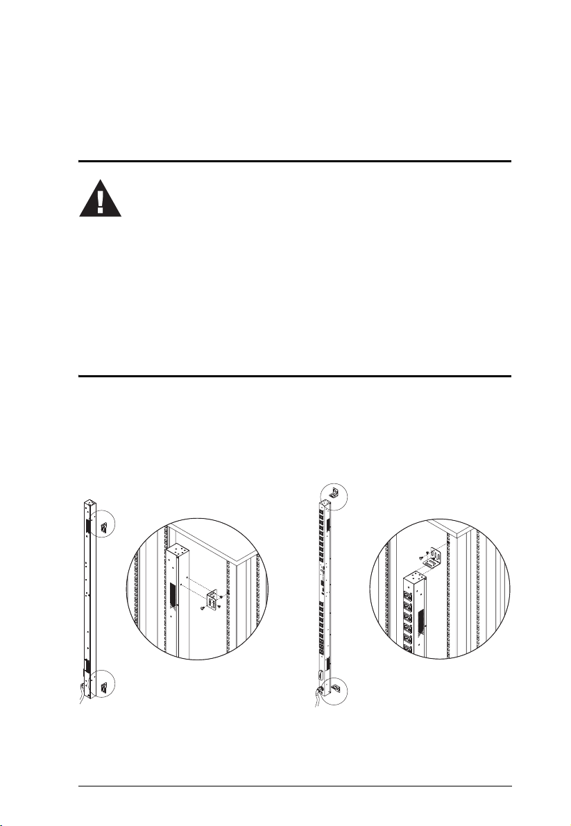
Rack Mounting
The PN7212 / PN7320 can be installed in a 0U configuration on the side of a
rack. To rack mount the device, use the rack mounting brackets that came with
your device. The brackets can be mounted either near the top and bottom of the
back panel, or the top and bottom ends of the device (see page 12), as shown
in the diagrams below:
(Continues on next page.)
11
PN7212 / PN7320 User Manual
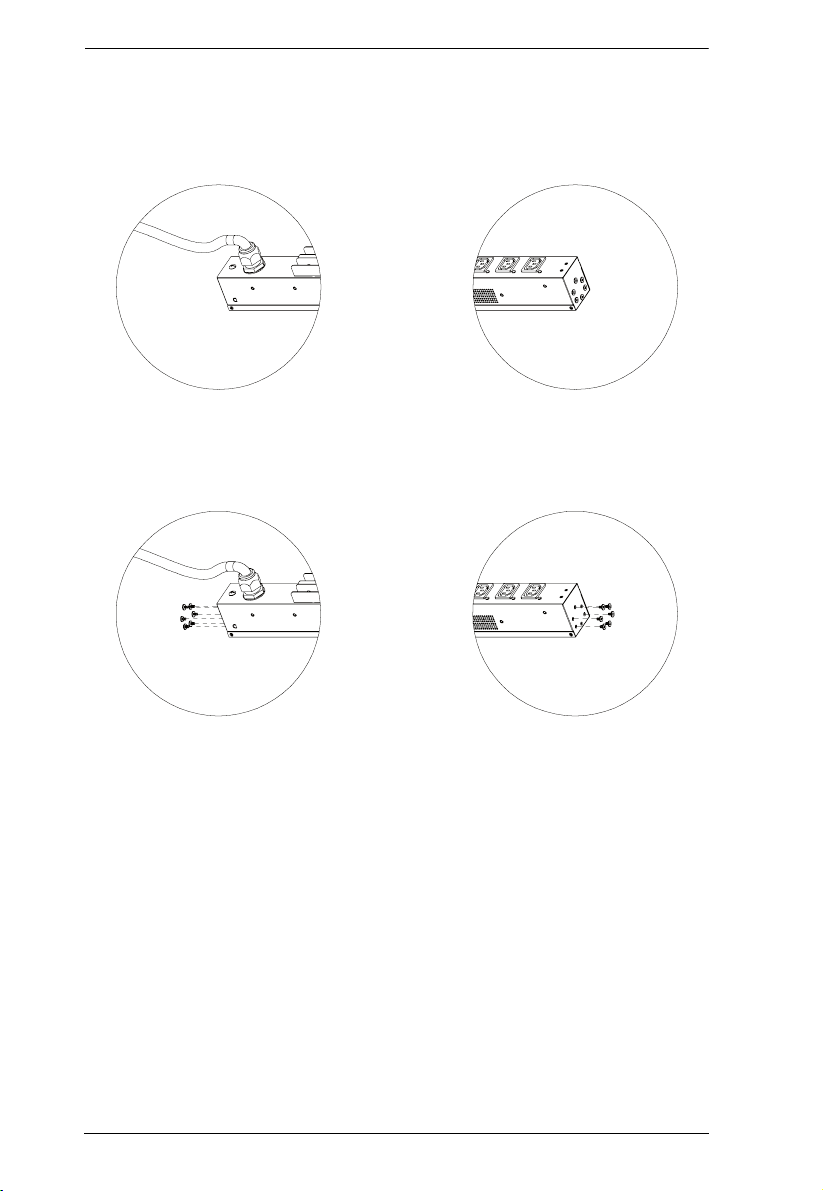
(Continued from previous page.)
The PN7212 / PN7320 comes supplied with top and bottom screws already
inserted, as shown below:
If you want to mount to brackets at the top and bottom ends of the device, you
must first remove the screws from each end of the unit before attaching the
mounting brackets:
12

Chapter 2. Hardware Setup
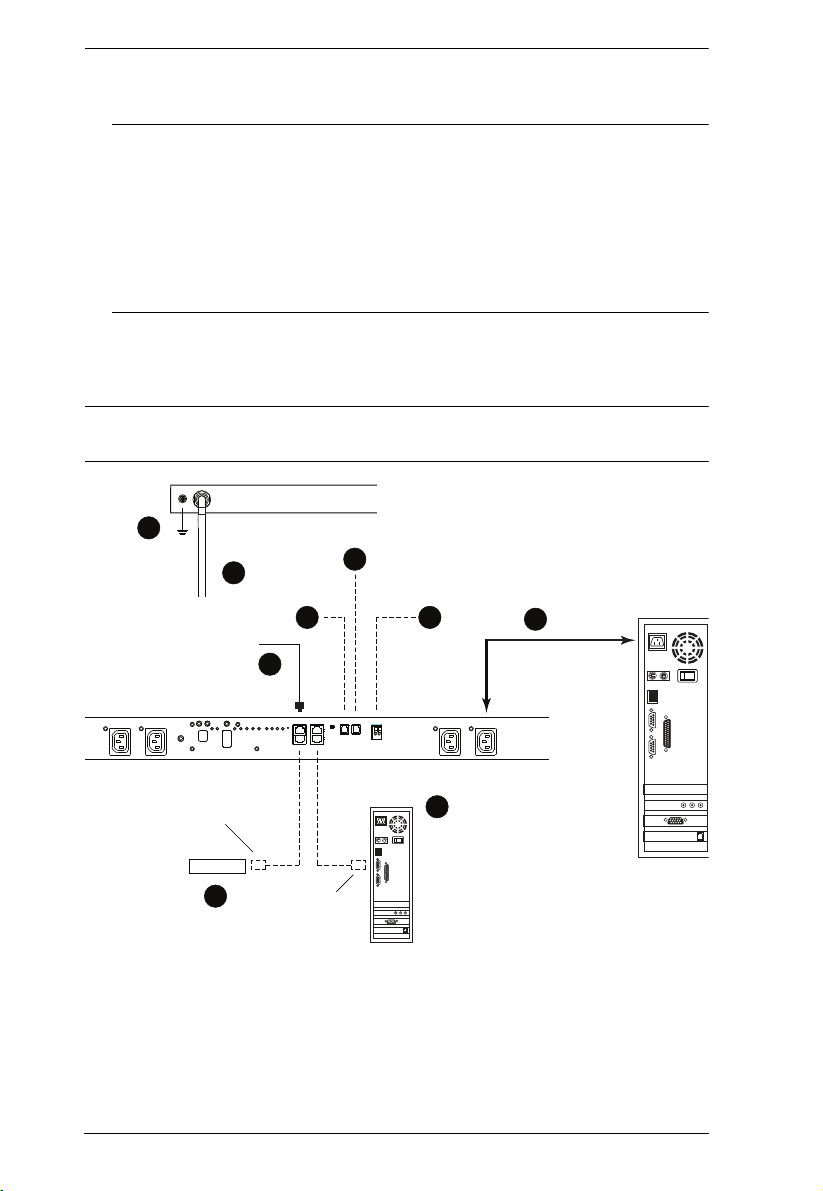
Single Stage Installation
In a Single Stage installation, there are no additional PN7212 / PN7320
Stations daisy chained down from the first unit. To set up a single stage
installation, refer to the installation diagram on the next page (the numbers in
the diagram correspond to the numbered steps), and do the following:
1. Use a grounding wire to ground the PN7212 / PN7320 by connecting one
end of the wire to its grounding terminal, and the other end of the wire to a
suitable grounded object.
Note: Do not omit this step. Proper grounding helps to prevent damage to
the unit from surges or static electricity.
2. For each device you want to connect, use its power cable to connect from
the device's AC socket to any available outlet on the PN7212 / PN7320.
3. Plug the cable that connects the PN7212 / PN7320 to the LAN into the
PN7212 / PN7320's LAN port.
4. (Optional) If you wish to connect a modem, use Cat 5e cable to connect
the PN7212 / PN7320’s Modem port to the SA0142 (DCE) adapter
supplied with your package. Connect the adapter’s serial connector to the
modem’s DB-9 port.
5. (Optional) If you wish to use a console terminal connection, use Cat 5e
cable to connect the PN7212 / PN7320’s PON IN/Console port to the
SA0151 (DTE) adapter supplied with your package. Connect the adapter’s
serial connector to the COM port of the computer you will use for the
console terminal.
6. (Optional) If you wish to connect a temperature or humidity sensor, its RJ11 connector plugs in here.
7. (Optional) If you wish to connect a digital output device, wire it to this
two-pin terminal.
(Continues on next page.)
13
PN7212 / PN7320 User Manual
3
6
9
7
8
5
4
2
1
Modem
SA0151
(DTE)
SA0142
(DCE)
8. Connect the PN7212 / PN7320's power cord to an AC power source.
Note: 1. We strongly advise that you do not plug the PN7212 / PN7320
into a multi socket extension cord, since it may not receive
enough amperage to operate correctly.
2. Circuit breakers are not provided on the PN7212. Therefore, we
strongly recommend that you do no plug the unit directly into any
unprotected power source (such as a wall outlet). See PN Device
Safety Notice, page iii.
Once you have finished these installation steps, you can turn on the PN7212 /
PN7320 and the connected devices.
Note: We strongly recommend using cable ties and cable bars to safely and
securely route the cables attached to the back of the unit.
14

Chapter 2. Hardware Setup
Daisy Chaining
To manage even more outlets from the same single session as a standalone
PN7212 / PN7320, additional Power Over the NET™ devices can be daisy
chained, as described in the following three configurations.
Note: The maximum distance between any two Power Over the NET™
devices must not exceed 15 m; the total distance from the first station to
the last must not exceed 100 m.
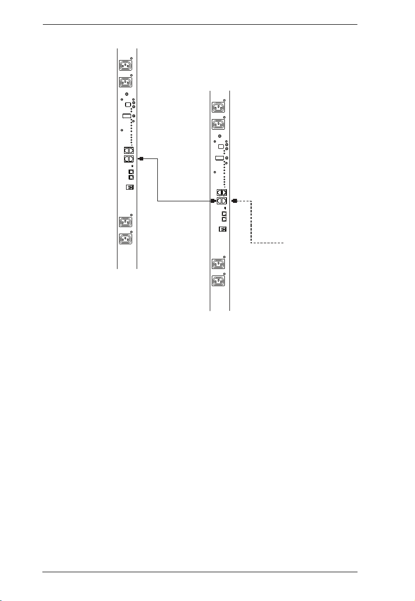
PN7212 / PN7320 to PN7212 / PN7320
Up to 15 additional PN7212 / PN7320 stations can be daisy chained down from
the top level (master) device – allowing up to 320 outlets to be managed on a
complete installation. To daisy chain a PN7212 / PN7320, do the following:
1. Set the RS-232/RS-485 switch (see page 10), of the child device to the RS232 setting.
2. Use Cat 5e cable to connect the PON OUT port of the parent device to the
PON IN port of the child device.
3. Repeat the procedure for any additional devices you wish to connect.
15
PN7212 / PN7320 User Manual
16
Chapter 2. Hardware Setup
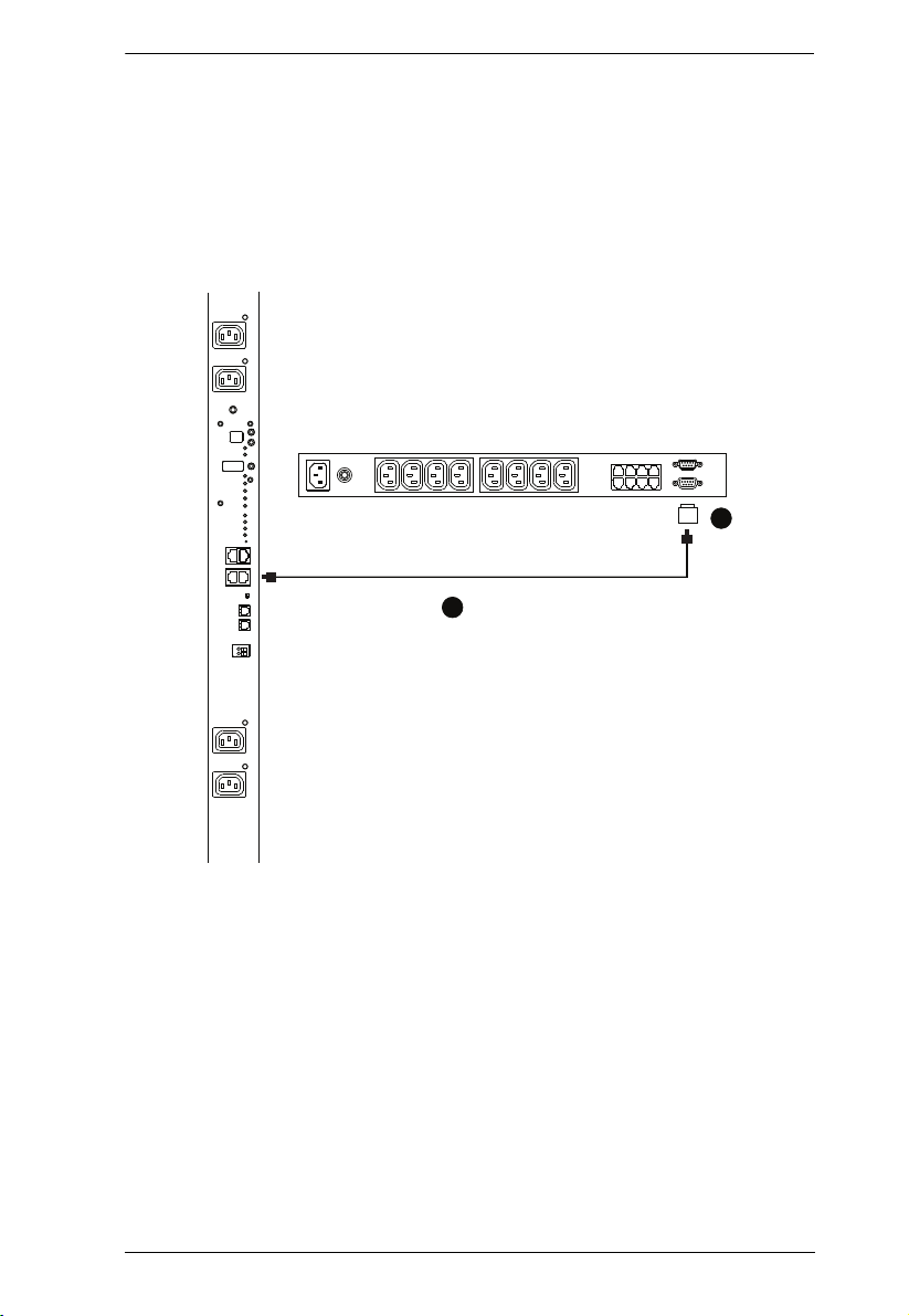
SA0150
1
2
PN7212 / PN7320 to PN0108
To daisy chain a child PN0108 from a parent PN7212 / PN7320, do the
following:
1. Use Cat 5e cable to connect the PN7212 / PN7320’s PON OUT port to the
SA0150 Adapter supplied with your package.
2. Connect the SA0150 to the PN0108’s PON IN port.
17
PN7212 / PN7320 User Manual
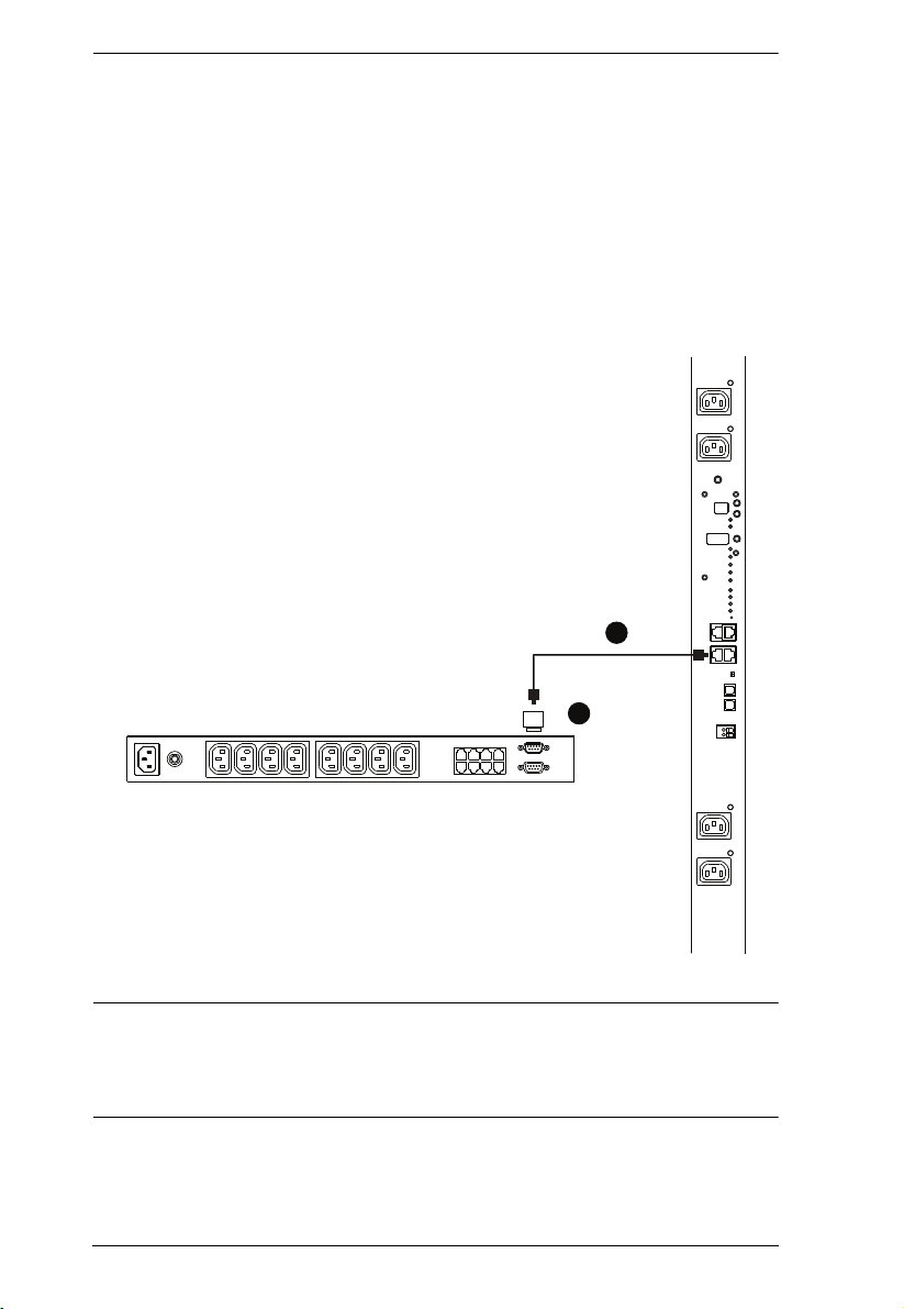
SA0149
1
2
PN0108 to PN7212 / PN7320
To daisy chain a PN7212 / PN7320 from a parent PN0108, do the following:
1. Set the RS-232/RS-485 switch (see page 10), of the child PN7212 /
PN7320 to the RS-232 setting.
2. Connect the SA0149 Adapter supplied with your package to the PN0108’s
PON OUT port.
3. Use Cat 5e cable to connect the SA0149 to the PN7212 / PN7320’s PON
IN port.
Note: In this configuration, the PN0108 would be connected to a KVM switch
that supports Power Over the NET™ devices (such as the KN4140v),
through its PON IN port, and the PON devices would be managed
through the KVM switch’s interface.
18
 Loading...