


 Loading...
KVM Over the NET™
KN9108 / KN9116
User Manual
www.altusen.com.tw

KN9108 / KN9116 User Manual
FCC Information
This is an FCC Class A product. In a domestic environment this product may cause radio interference in which case the user may be required to take adequate measures.
This equipment has been tested and found to comply with the limits for a Class A digital device, pursuant to Part 15 of the FCC Rules. These limits are designed to provide reasonable protection against harmful interference when the equipment is operated in a commercial environment. This equipment generates, uses and can radiate radio frequency energy and, if not installed and used in accordance with the instruction manual, may cause harmful interference to radio communications. Operation of this equipment in a residential area is likely to cause harmful interference in which case the user will be required to correct the interference at his own expense.
RoHS
This product is RoHS compliant.
SJ/T 11364-2006
The following contains information that relates to China.
ii

KN9108 / KN9116 User Manual
User Information
Online Registration
Be sure to register your product at our online support center:
International – http://support.aten.com
North America – http://www.aten-usa.com/product_registration
Telephone Support
International – 886-2-8692-6959
North America – 1-888-999-ATEN
User Notice
All information, documentation, and specifications contained in this manual are subject to change without prior notification by the manufacturer. The manufacturer makes no representations or warranties, either expressed or implied, with respect to the contents hereof and specifically disclaims any warranties as to merchantability or fitness for any particular purpose. Any of the manufacturer's software described in this manual is sold or licensed `as is'. Should the programs prove defective following their purchase, the buyer (and not the manufacturer, its distributor, or its dealer), assumes the entire cost of all necessary servicing, repair and any incidental or consequential damages resulting from any defect in the software.
The manufacturer of this system is not responsible for any radio and/or TV interference caused by unauthorized modifications to this device. It is the responsibility of the user to correct such interference.
The manufacturer is not responsible for any damage incurred in the operation of this system if the correct operational voltage setting was not selected prior to operation. PLEASE VERIFY THAT THE VOLTAGE SETTING IS CORRECT BEFORE USE.
iii

KN9108 / KN9116 User Manual
Package Contents
The KN9108 / KN9116 package consists of:
1KN9108 or KN9116 KVM Over the NET™ KVM Switch
2Custom KVM Cable Sets
1 Power Cord
1 Rack Mount Kit
1 Foot Pad Set (4 Pads)
1 User Manual*
1 Quick Start Guide
Check to make sure that all of the components are present and in good order. If anything is missing, or was damaged in shipping, contact your dealer.
Read this manual thoroughly and follow the installation and operation procedures carefully to prevent any damage to the switch or to any other devices on the installation.
*Features may have been added to the KN9108 / KN9116 since this manual was printed. Please visit our website to download the most up to date version of the manual.
Copyright © 2006 ATEN® International Co., Ltd.
Manual Part No. PAPE-0205-4AXG
Printing Date: 09/2007
ATEN and the ATEN logo are registered trademarks of ATEN International Co., Ltd. All rights reserved. All other brand names and trademarks are the registered property of their respective owners.
iv

KN9108 / KN9116 User Manual
Contents
FCC Information . . . . . . . . . . . . . . . . . . . . . . . . . . . . . . . . . . . . . . . . . . . . . ii SJ/T 11364-2006. . . . . . . . . . . . . . . . . . . . . . . . . . . . . . . . . . . . . . . . . . . . . ii
User Information . . . . . . . . . . . . . . . . . . . . . . . . . . . . . . . . . . . . . . . . . . . . .iii Online Registration . . . . . . . . . . . . . . . . . . . . . . . . . . . . . . . . . . . . . . . .iii
Telephone Support . . . . . . . . . . . . . . . . . . . . . . . . . . . . . . . . . . . . . . . .iii User Notice . . . . . . . . . . . . . . . . . . . . . . . . . . . . . . . . . . . . . . . . . . . . . .iii
Package Contents. . . . . . . . . . . . . . . . . . . . . . . . . . . . . . . . . . . . . . . . . . . iv About This Manual . . . . . . . . . . . . . . . . . . . . . . . . . . . . . . . . . . . . . . . . . . ix Overview . . . . . . . . . . . . . . . . . . . . . . . . . . . . . . . . . . . . . . . . . . . . . . . ix
Conventions . . . . . . . . . . . . . . . . . . . . . . . . . . . . . . . . . . . . . . . . . . . . . x Product Information. . . . . . . . . . . . . . . . . . . . . . . . . . . . . . . . . . . . . . . . . . . x
Chapter 1.
Introduction
Features . . . . . . . . . . . . . . . . . . . . . . . . . . . . . . . . . . . . . . . . . . . . . . . . . . . 3 System Requirements. . . . . . . . . . . . . . . . . . . . . . . . . . . . . . . . . . . . . . . . . 4 Remote Computers . . . . . . . . . . . . . . . . . . . . . . . . . . . . . . . . . . . . . . . . 4
Computers. . . . . . . . . . . . . . . . . . . . . . . . . . . . . . . . . . . . . . . . . . . . . . . 4
Cables . . . . . . . . . . . . . . . . . . . . . . . . . . . . . . . . . . . . . . . . . . . . . . . . . . 5 Components . . . . . . . . . . . . . . . . . . . . . . . . . . . . . . . . . . . . . . . . . . . . . . . . 6 Front View . . . . . . . . . . . . . . . . . . . . . . . . . . . . . . . . . . . . . . . . . . . . . . . 6
KN9108:. . . . . . . . . . . . . . . . . . . . . . . . . . . . . . . . . . . . . . . . . . . . . . 6 KN9116:. . . . . . . . . . . . . . . . . . . . . . . . . . . . . . . . . . . . . . . . . . . . . . 6 Rear View . . . . . . . . . . . . . . . . . . . . . . . . . . . . . . . . . . . . . . . . . . . . . . . 8
KN9108:. . . . . . . . . . . . . . . . . . . . . . . . . . . . . . . . . . . . . . . . . . . . . . 8 KN9116:. . . . . . . . . . . . . . . . . . . . . . . . . . . . . . . . . . . . . . . . . . . . . . 8
Chapter 2.
Hardware Setup
Rack Mounting . . . . . . . . . . . . . . . . . . . . . . . . . . . . . . . . . . . . . . . . . . . . . 12 Installation . . . . . . . . . . . . . . . . . . . . . . . . . . . . . . . . . . . . . . . . . . . . . . . . . 13 Hot Plugging . . . . . . . . . . . . . . . . . . . . . . . . . . . . . . . . . . . . . . . . . . . . . . . 14 Port ID Numbering . . . . . . . . . . . . . . . . . . . . . . . . . . . . . . . . . . . . . . . . . . 14
Powering Off and Restarting . . . . . . . . . . . . . . . . . . . . . . . . . . . . . . . . . . . 14 Port Selection . . . . . . . . . . . . . . . . . . . . . . . . . . . . . . . . . . . . . . . . . . . . . . 14
Chapter 3.
Administration
The Local Console . . . . . . . . . . . . . . . . . . . . . . . . . . . . . . . . . . . . . . . . . . 15 The Main Page . . . . . . . . . . . . . . . . . . . . . . . . . . . . . . . . . . . . . . . . . . . . . 17 Quick View Ports . . . . . . . . . . . . . . . . . . . . . . . . . . . . . . . . . . . . . . . . . 17
The List Function. . . . . . . . . . . . . . . . . . . . . . . . . . . . . . . . . . . . . . . . . 18 Port Names . . . . . . . . . . . . . . . . . . . . . . . . . . . . . . . . . . . . . . . . . . . . . 20 Port Operation. . . . . . . . . . . . . . . . . . . . . . . . . . . . . . . . . . . . . . . . . . . . . . 21
v

KN9108 / KN9116 User Manual
The Configuration Page . . . . . . . . . . . . . . . . . . . . . . . . . . . . . . . . . . . . . . 22
The Log Page . . . . . . . . . . . . . . . . . . . . . . . . . . . . . . . . . . . . . . . . . . . . . . 22
The Administration Page . . . . . . . . . . . . . . . . . . . . . . . . . . . . . . . . . . . . . 23
General . . . . . . . . . . . . . . . . . . . . . . . . . . . . . . . . . . . . . . . . . . . . . . . . 23
User Management. . . . . . . . . . . . . . . . . . . . . . . . . . . . . . . . . . . . . . . . 24
Service Configuration . . . . . . . . . . . . . . . . . . . . . . . . . . . . . . . . . . . . . 27
Access Port . . . . . . . . . . . . . . . . . . . . . . . . . . . . . . . . . . . . . . . . . . 27
Log Server. . . . . . . . . . . . . . . . . . . . . . . . . . . . . . . . . . . . . . . . . . . 28
Network . . . . . . . . . . . . . . . . . . . . . . . . . . . . . . . . . . . . . . . . . . . . . . . . 29
IP Address. . . . . . . . . . . . . . . . . . . . . . . . . . . . . . . . . . . . . . . . . . . 29
DNS Server . . . . . . . . . . . . . . . . . . . . . . . . . . . . . . . . . . . . . . . . . . 29
RADIUS. . . . . . . . . . . . . . . . . . . . . . . . . . . . . . . . . . . . . . . . . . . . . . . . 30
Security . . . . . . . . . . . . . . . . . . . . . . . . . . . . . . . . . . . . . . . . . . . . . . . . 33
Customization . . . . . . . . . . . . . . . . . . . . . . . . . . . . . . . . . . . . . . . . . . 35
Login Failures . . . . . . . . . . . . . . . . . . . . . . . . . . . . . . . . . . . . . . . . 35
Working Mode . . . . . . . . . . . . . . . . . . . . . . . . . . . . . . . . . . . . . . . . 35
Attributes . . . . . . . . . . . . . . . . . . . . . . . . . . . . . . . . . . . . . . . . . . . . 36
Timeout . . . . . . . . . . . . . . . . . . . . . . . . . . . . . . . . . . . . . . . . . . . . . 38
Miscellaneous . . . . . . . . . . . . . . . . . . . . . . . . . . . . . . . . . . . . . . . . 39
Date/Time . . . . . . . . . . . . . . . . . . . . . . . . . . . . . . . . . . . . . . . . . . . . . . 40
Upgrading the Firmware . . . . . . . . . . . . . . . . . . . . . . . . . . . . . . . . . . . . . . 41
Chapter 4.
Browser Operation
Logging In . . . . . . . . . . . . . . . . . . . . . . . . . . . . . . . . . . . . . . . . . . . . . . . . . 43
Web Page Layout . . . . . . . . . . . . . . . . . . . . . . . . . . . . . . . . . . . . . . . . . . . 45
The General Dialog Box . . . . . . . . . . . . . . . . . . . . . . . . . . . . . . . . . . . 45
Web Page Icons . . . . . . . . . . . . . . . . . . . . . . . . . . . . . . . . . . . . . . . . . 46
Web Page Buttons . . . . . . . . . . . . . . . . . . . . . . . . . . . . . . . . . . . . . . . 47
Chapter 5.
The Windows Client
The Main Page . . . . . . . . . . . . . . . . . . . . . . . . . . . . . . . . . . . . . . . . . . . . . 51
Port Operation . . . . . . . . . . . . . . . . . . . . . . . . . . . . . . . . . . . . . . . . . . . . . 53
The OSD Toolbar . . . . . . . . . . . . . . . . . . . . . . . . . . . . . . . . . . . . . . . . 53
Recalling the OSD. . . . . . . . . . . . . . . . . . . . . . . . . . . . . . . . . . . . . . . . 53
OSD Hotkey Summary Table . . . . . . . . . . . . . . . . . . . . . . . . . . . . . . . 54
The Toolbar Icons . . . . . . . . . . . . . . . . . . . . . . . . . . . . . . . . . . . . . . . . 54
Hotkey Operation . . . . . . . . . . . . . . . . . . . . . . . . . . . . . . . . . . . . . . . . 55
Auto Scanning . . . . . . . . . . . . . . . . . . . . . . . . . . . . . . . . . . . . . . . . 55
Setting the Scan Interval . . . . . . . . . . . . . . . . . . . . . . . . . . . . . . . . 55
Invoking Auto Scan . . . . . . . . . . . . . . . . . . . . . . . . . . . . . . . . . . . . 55
Pausing Auto Scan . . . . . . . . . . . . . . . . . . . . . . . . . . . . . . . . . . . . 56
Exiting Auto Scan . . . . . . . . . . . . . . . . . . . . . . . . . . . . . . . . . . . . . 56
Skip Mode . . . . . . . . . . . . . . . . . . . . . . . . . . . . . . . . . . . . . . . . . . . 56
Panel Array Mode . . . . . . . . . . . . . . . . . . . . . . . . . . . . . . . . . . . . . . . . 57
Multiuser Operation. . . . . . . . . . . . . . . . . . . . . . . . . . . . . . . . . . . . . . . 59
vi

KN9108 / KN9116 User Manual
Windows Client Control Panel. . . . . . . . . . . . . . . . . . . . . . . . . . . . . . . . . . 60
Hotkeys . . . . . . . . . . . . . . . . . . . . . . . . . . . . . . . . . . . . . . . . . . . . . . . . 61
Video Adjustment . . . . . . . . . . . . . . . . . . . . . . . . . . . . . . . . . . . . . . . . 63
Gamma Adjustment . . . . . . . . . . . . . . . . . . . . . . . . . . . . . . . . . . . . 65
The Message Board . . . . . . . . . . . . . . . . . . . . . . . . . . . . . . . . . . . . . . 66
The Button Bar. . . . . . . . . . . . . . . . . . . . . . . . . . . . . . . . . . . . . . . . 67
Message Display Panel . . . . . . . . . . . . . . . . . . . . . . . . . . . . . . . . . 67
Compose Panel . . . . . . . . . . . . . . . . . . . . . . . . . . . . . . . . . . . . . . . 67
User List Panel . . . . . . . . . . . . . . . . . . . . . . . . . . . . . . . . . . . . . . . 68
Keyboard and Mouse Considerations . . . . . . . . . . . . . . . . . . . . . . . . . . . . 69
Keystrokes. . . . . . . . . . . . . . . . . . . . . . . . . . . . . . . . . . . . . . . . . . . . . . 69
Mouse Synchronization . . . . . . . . . . . . . . . . . . . . . . . . . . . . . . . . . . . . 70
The Configuration Page . . . . . . . . . . . . . . . . . . . . . . . . . . . . . . . . . . . . . . 71
Chapter 6.
The Java Client
The Java Client Control Panel . . . . . . . . . . . . . . . . . . . . . . . . . . . . . . . . . 74
Set Video Parameters . . . . . . . . . . . . . . . . . . . . . . . . . . . . . . . . . . . . . 75
Keypad . . . . . . . . . . . . . . . . . . . . . . . . . . . . . . . . . . . . . . . . . . . . . . . . 75
Mouse Synchronization . . . . . . . . . . . . . . . . . . . . . . . . . . . . . . . . . . . . 76
Message Board . . . . . . . . . . . . . . . . . . . . . . . . . . . . . . . . . . . . . . . . . . 76
The Button Bar. . . . . . . . . . . . . . . . . . . . . . . . . . . . . . . . . . . . . . . . 77
Lock Key LEDs . . . . . . . . . . . . . . . . . . . . . . . . . . . . . . . . . . . . . . . . . . 79
Resolution . . . . . . . . . . . . . . . . . . . . . . . . . . . . . . . . . . . . . . . . . . . . . . 79
Switch Screen Mode . . . . . . . . . . . . . . . . . . . . . . . . . . . . . . . . . . . . . . 79
About . . . . . . . . . . . . . . . . . . . . . . . . . . . . . . . . . . . . . . . . . . . . . . . . . . 79
Help . . . . . . . . . . . . . . . . . . . . . . . . . . . . . . . . . . . . . . . . . . . . . . . . . . . 79
Exit . . . . . . . . . . . . . . . . . . . . . . . . . . . . . . . . . . . . . . . . . . . . . . . . . . . 79
Port Operation. . . . . . . . . . . . . . . . . . . . . . . . . . . . . . . . . . . . . . . . . . . . . . 80
Panel Array Mode . . . . . . . . . . . . . . . . . . . . . . . . . . . . . . . . . . . . . . . . 80
Hotkey Operation . . . . . . . . . . . . . . . . . . . . . . . . . . . . . . . . . . . . . . . . . . . 80
The Configuration Page . . . . . . . . . . . . . . . . . . . . . . . . . . . . . . . . . . . . . . 80
Chapter 7.
The Log File
Chapter 8.
The Log Server
Installation . . . . . . . . . . . . . . . . . . . . . . . . . . . . . . . . . . . . . . . . . . . . . . . . . 83
Starting Up . . . . . . . . . . . . . . . . . . . . . . . . . . . . . . . . . . . . . . . . . . . . . . . . 84
The Menu Bar . . . . . . . . . . . . . . . . . . . . . . . . . . . . . . . . . . . . . . . . . . . . . . 85
Configure. . . . . . . . . . . . . . . . . . . . . . . . . . . . . . . . . . . . . . . . . . . . . . . 85
Events . . . . . . . . . . . . . . . . . . . . . . . . . . . . . . . . . . . . . . . . . . . . . . . . . 86
Search . . . . . . . . . . . . . . . . . . . . . . . . . . . . . . . . . . . . . . . . . . . . . . 86
Maintenance . . . . . . . . . . . . . . . . . . . . . . . . . . . . . . . . . . . . . . . . . 88
Options . . . . . . . . . . . . . . . . . . . . . . . . . . . . . . . . . . . . . . . . . . . . . . . . 88
Help . . . . . . . . . . . . . . . . . . . . . . . . . . . . . . . . . . . . . . . . . . . . . . . . . . . 88
vii

KN9108 / KN9116 User Manual
The Log Server Main Screen . . . . . . . . . . . . . . . . . . . . . . . . . . . . . . . . . . 89
Overview . . . . . . . . . . . . . . . . . . . . . . . . . . . . . . . . . . . . . . . . . . . . . . . 89
The List Panel . . . . . . . . . . . . . . . . . . . . . . . . . . . . . . . . . . . . . . . . . . . 90
The Event Panel . . . . . . . . . . . . . . . . . . . . . . . . . . . . . . . . . . . . . . . . . 90
Chapter 9.
AP Operation
The Windows Client . . . . . . . . . . . . . . . . . . . . . . . . . . . . . . . . . . . . . . . . . 91
Installation . . . . . . . . . . . . . . . . . . . . . . . . . . . . . . . . . . . . . . . . . . . . . . 91
Starting Up . . . . . . . . . . . . . . . . . . . . . . . . . . . . . . . . . . . . . . . . . . . . . 92
Keyboard . . . . . . . . . . . . . . . . . . . . . . . . . . . . . . . . . . . . . . . . . . . . 94
Connecting . . . . . . . . . . . . . . . . . . . . . . . . . . . . . . . . . . . . . . . . . . . . . 96
Operation . . . . . . . . . . . . . . . . . . . . . . . . . . . . . . . . . . . . . . . . . . . . . . 97
The Java Client. . . . . . . . . . . . . . . . . . . . . . . . . . . . . . . . . . . . . . . . . . . . . 98
Installation . . . . . . . . . . . . . . . . . . . . . . . . . . . . . . . . . . . . . . . . . . . . . . 98
Starting Up . . . . . . . . . . . . . . . . . . . . . . . . . . . . . . . . . . . . . . . . . . . . . 98
Operation . . . . . . . . . . . . . . . . . . . . . . . . . . . . . . . . . . . . . . . . . . . . . 100
Appendix
Safety Instructions . . . . . . . . . . . . . . . . . . . . . . . . . . . . . . . . . . . . . . . . . 101
General . . . . . . . . . . . . . . . . . . . . . . . . . . . . . . . . . . . . . . . . . . . . . . . 101
Rack Mounting . . . . . . . . . . . . . . . . . . . . . . . . . . . . . . . . . . . . . . . . . 103
Technical Support. . . . . . . . . . . . . . . . . . . . . . . . . . . . . . . . . . . . . . . . . . 104
International . . . . . . . . . . . . . . . . . . . . . . . . . . . . . . . . . . . . . . . . . . . 104
North America . . . . . . . . . . . . . . . . . . . . . . . . . . . . . . . . . . . . . . . . . . 104
Troubleshooting . . . . . . . . . . . . . . . . . . . . . . . . . . . . . . . . . . . . . . . . . . . 105
Administration . . . . . . . . . . . . . . . . . . . . . . . . . . . . . . . . . . . . . . . . . . 105
General Operation. . . . . . . . . . . . . . . . . . . . . . . . . . . . . . . . . . . . . . . 105
The Java Client . . . . . . . . . . . . . . . . . . . . . . . . . . . . . . . . . . . . . . . . . 106
The Log Server . . . . . . . . . . . . . . . . . . . . . . . . . . . . . . . . . . . . . . . . . 106
Panel Array Mode . . . . . . . . . . . . . . . . . . . . . . . . . . . . . . . . . . . . . . . 107
The Windows Client . . . . . . . . . . . . . . . . . . . . . . . . . . . . . . . . . . . . . 107
Sun Systems . . . . . . . . . . . . . . . . . . . . . . . . . . . . . . . . . . . . . . . . . . . 108
Additional Mouse Synchronization Procedures. . . . . . . . . . . . . . . . . 109
Administrator Login Failure. . . . . . . . . . . . . . . . . . . . . . . . . . . . . . . . . . . 111
Specifications . . . . . . . . . . . . . . . . . . . . . . . . . . . . . . . . . . . . . . . . . . . . . 112
Compatible Cascade Switches . . . . . . . . . . . . . . . . . . . . . . . . . . . . . . . . 113
OSD Factory Default Settings. . . . . . . . . . . . . . . . . . . . . . . . . . . . . . . . . 113
About SPHD Connectors . . . . . . . . . . . . . . . . . . . . . . . . . . . . . . . . . . . . 113
Trusted Certificates. . . . . . . . . . . . . . . . . . . . . . . . . . . . . . . . . . . . . . . . . 114
Overview . . . . . . . . . . . . . . . . . . . . . . . . . . . . . . . . . . . . . . . . . . . . . . 114
Installing the Certificate. . . . . . . . . . . . . . . . . . . . . . . . . . . . . . . . . . . 115
Certificate Trusted. . . . . . . . . . . . . . . . . . . . . . . . . . . . . . . . . . . . . . . 116
Limited Warranty. . . . . . . . . . . . . . . . . . . . . . . . . . . . . . . . . . . . . . . . . . . 117
viii

KN9108 / KN9116 User Manual
About This Manual
This User Manual is provided to help you get the most from your CC1000 system. It covers all aspects of installation, configuration and operation. An overview of the information found in the manual is provided below.
Overview
Chapter 1, Introduction, introduces you to the KN9108 / KN9116 System. Its purpose, features and benefits are presented, and its front and back panel components are described.
Chapter 2, Hardware Setup, provides step-by-step instructions for setting up your installation, and explains some basic operation procedures.
Chapter 3, Administration, explains the administrative procedures that are employed to configure the KN9108 / KN9116’s working environment, as well as how to operate the KN9108 / KN9116 from the local console.
Chapter 4, Browser Operation, describes how to log into the KN9108 / KN9116 with your browser, and explains the functions of the icons and buttons on the KN9108 / KN9116 web page.
Chapter 5, The Windows Client, explains how to connect to the KN9108 / KN9116 with the Windows Client software, and describes how to use the OSD to access and control the computers connected to the switch.
Chapter 6, The Java Client, describes how to connect to the KN9108 / KN9116 with the Java Client software, and explains how to use the OSD to access and control the computers connected to the switch.
Chapter 7, The Log File, shows how to use the log file utility to view all the events that take place on the KN9108 / KN9116.
Chapter 8, The Log Server, explains how to install and configure the Log Server.
Chapter 9, AP Operation, describes how to operate the KN9108 / KN9116 using Windows and Java Client application programs, rather than with the browser method.
An Appendix, at the end of the manual provides technical and troubleshooting information.
ix

KN9108 / KN9116 User Manual
Conventions
This manual uses the following conventions:
Monospaced |
Indicates text that you should key in. |
[ ] |
Indicates keys you should press. For example, [Enter] means |
|
to press the Enter key. If keys need to be chorded, they |
|
appear together in the same bracket with a plus sign |
|
between them: [Ctrl+Alt]. |
1.Numbered lists represent procedures with sequential steps.
♦Bullet lists provide information, but do not involve sequential steps.
→Indicates selecting the option (on a menu or dialog box, for example), that comes next. For example, Start →Run means to open the Start menu, and then select Run.
Indicates critical information.
Product Information
For information about all ALTUSEN products and how they can help you connect without limits, visit ALTUSEN on the Web or contact an ALTUSEN Authorized Reseller. Visit ALTUSEN on the Web for a list of locations and telephone numbers
International – http://www.aten.com
North America – http://www.aten-usa.com
x
Chapter 1
Introduction
Overview
The KN9108 / KN9116 is an IP-based KVM control unit that allows both local and remote operators to monitor and access multiple computers from multiple consoles. A single KN9108 / KN9116 can control up to 8 / 16 computers.
Since the KN9108 / KN9116 uses TCP/IP for its communications protocol, it can be accessed from any computer on the Net - whether that computer is located down the hall, down the street, or halfway around the world.
Remote
KN9108 / KN9116
Local
Access to any computer connected to the installation from the local console is easily accomplished by means of a powerful mouse driven graphical OSD (On Screen Display) menu system. A convenient Auto Scan feature also permits automatic scanning and monitoring of the activities of all computers running on the installation one by one.
Remote consoles connect to the KN9108 / KN9116 via its IP address. Software utilities are provided with the KN9108 / KN9116 that make remote access smooth and efficient. System administrators can handle a multitude of maintenance tasks with ease - from installing and running GUI applications, to BIOS level troubleshooting, routine monitoring, concurrent maintenance, system administration, rebooting and even pre-booting functions - all from the remote console.
1

KN9108 / KN9116 User Manual
Remote operators can log in from anywhere on the LAN, WAN, or Internet via their browsers. Once they successfully log in, operators can take control using either the Windows Client or Java Client utility. Inclusion of a Java-based client ensures that the KN9108 / KN9116 is platform independent, and is able to work with all operating systems.
The client software allows operators to exchange keyboard, video and mouse signals with the computers attached to the KN9108 / KN9116 just as if they were present locally and working on the equipment directly.
With the KN9108 / KN9116's Panel Array feature, the video output of up to 8 / 16 computers can be displayed at the same time.
The Message Board allows widely separated users to conveniently and instantly communicate with one other. It also includes features that allow users to take control of share ports.
The KN9108 / KN9116 features high density 15 pin CPU port connectors instead of the usual 25 pin connectors. This space-saving innovation allows a full 8 / 16 port switch to be conveniently installed in one unit of system rack space.
Setup is fast and easy - plugging cables into their appropriate ports is all that is entailed. Because the KN9108 / KN9116 intercepts keyboard input directly, there is no need to get involved in complex installation routines or to be concerned with incompatibility problems.
Since the KN9108 / KN9116's firmware is upgradable over the Internet, you can stay current with the latest functionality improvements simply by downloading firmware updates from our website as they become available.
With its advanced security features, the KN9108 / KN9116 is the fastest, most reliable, most cost effective way to remotely access and manage widely distributed multiple computer installations.
2

Chapter 1. Introduction
Features
8 (KN9108) / 16 (KN9116) port remote access KVM switch - monitor and control up to 8 / 16 computers from a single KVM (Keyboard, Video, Mouse) console
Remotely access computers via LAN, WAN, or the Internet - control your installation when and where you want
Dual-bus: one local and one remote user can simultaneously control separate ports
Internet browser access, Windows Client and Java Client provided, Java Client works with all operating systems*
Graphical OSD and graphical toolbars for convenient, user-friendly operation
Up to 64 user accounts - up to 32 concurrent logins
Panel Array Mode - view all 8 or 16 ports at the same time
Message board feature allows logged in users to communicate with each other and allows a user to take exclusive control of the KVM functions
Windows-based Log Server
Remote power control for attached Power over the Net™ devices
Three level login security: Administrator, User, and Select
Advanced security features include password protection and advanced encryption technologies - 1024 bit RSA, 256 bit AES, 56 bit DES, and 128 bit SSL
RADIUS server support
Flash upgradable firmware over network connection
Ports can be set to Exclusive, Occupy and Share
Supports 10Base-T, 100Base-T, TCP/IP, HTTP, and HTTPS
High video resolution: up to 1280 x 1024 @ 75Hz; 1600 x 1200 @ 60Hz
Front panel can separate from main chassis for convenient front and rear 1U rack mounting
* Browsers must support 128 bit SSL encryption.
3

KN9108 / KN9116 User Manual
System Requirements
Remote Computers
For best results, computers that remotely access the KN9108 / KN9116 should have at least a P III 1 GHz processor, with their screen resolution set to 1024 x 768.
Users who want to access the KN9108 / KN9116 with the Windows Client must have DirectX 7.0 or higher installed.
If you don't already have it, DirectX is available for free download from Microsoft's web site: http://www.microsoft.com/downloads.
Users who want to access the KN9108 / KN9116 with the Java Client must have Sun's Java 2 (1.4.2 or higher) runtime environment installed. Java is available for free download from the Sun Java website: http:// java.sun.com
Browsers must support 128 bit SSL encryption.
For best results, a network transfer speed of at least 128 kbps is recommended.
Computers
The following equipment must be installed on the computers that connect to the KN9108 / KN9116's CPU ports:
A VGA, SVGA or Multisync port.
A 6-pin mini-DIN (PS/2 style) keyboard port.
A 6-pin mini-DIN (PS/2 Style) mouse port.
4

Chapter 1. Introduction
Cables
Substandard cables may damage the connected devices or degrade overall performance. If you need additional cables, we strongly recommend that you see your dealer to purchase our high quality CS Custom Cable sets.
Part Number |
Length (m) |
|
|
2L-5201P |
1.2 |
|
|
2L-5202P |
1.8 |
|
|
2L-5203P |
3.0 |
|
|
2L-5206P |
6.0 |
|
|
2L-5702P |
1.8 |
|
|
5
KN9108 / KN9116 User Manual
Components
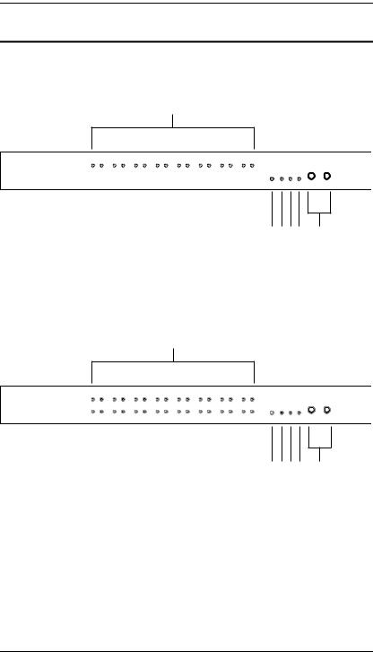
Front View
KN9108:
1
2 |
3 4 5 |
6 |
KN9116:
1
2 |
3 4 5 |
6 |
6

Chapter 1. Introduction
|
|
|
|
|
|
No. |
Component |
Description |
|
|
|
1 |
Port LEDs |
The Port LEDs provide status information about their |
|
|
corresponding KVM Ports. There is one pair of LEDs for |
|
|
each Port. The one on the left is the On Line LED; the one |
|
|
on the right is the Selected Port LED: |
|
|
An On Line LED lights GREEN to indicate that the |
|
|
computer attached to its corresponding port is up and |
|
|
running. |
|
|
A Selected LED lights ORANGE to indicate that the |
|
|
computer attached to its corresponding port is the one |
|
|
that has the KVM focus. The LED is steady under |
|
|
normal conditions, but flashes when its port is accessed |
|
|
under Auto Scan Mode (see Auto Scanning, page 55). |
|
|
When the KN9108 / KN9116 is first powered on, the On |
|
|
Line and Selected LEDs blink in sequence as the Switch |
|
|
performs a self-test. |
|
|
|
2 |
Reset Switch |
Note: This switch is recessed and must be pushed with a |
|
|
thin object - such as the end of a paper clip, or a ballpoint |
|
|
pen. |
|
|
Pressing and holding this switch in while powering on |
|
|
the KN9108 / KN9116 makes the switch use the factory |
|
|
installed firmware version rather than the firmware |
|
|
version that the switch has been upgraded to. This |
|
|
allows you to recover from a failed firmware upgrade |
|
|
and gives you the opportunity to try upgrading the |
|
|
firmware again. |
|
|
Pressing and holding this switch in for more than two |
|
|
seconds performs a system reset. |
|
|
|
3 |
Link LED |
Flashes GREEN to indicate that a Client program is |
|
|
accessing the device. |
|
|
|
4 |
10/100 Mbps |
The LED lights ORANGE to indicate 10 Mbps data |
|
Data LED |
transmission speed. |
|
|
The LED lights GREEN to indicate 100 Mbps data |
|
|
transmission speed. |
|
|
|
5 |
Power LED |
Lights when the KN9108 / KN9116 is powered up and |
|
|
ready to operate. |
|
|
|
6 |
Port Switching |
Press Port DOWN to switch from the current port to the |
|
Buttons |
previous port on the installation. |
Press Port UP to switch from the current port to the next port on the installation.
7
KN9108 / KN9116 User Manual
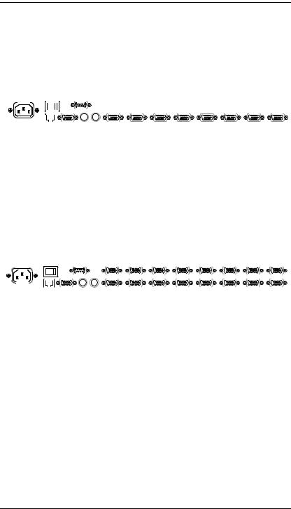
Rear View
KN9108:
|
|
1 |
|
|
|
2 |
|
|
3 |
|
|
|
|
4 |
|
|
|
|
|
|
|
||||||||||||||||
|
|
|
|
|
|
|
|
|
|
|
|
|
|
|
|
|
|
|
|
|
|
|
|
|
|
|
|
|
|
|
|
|
|
|
|
|
|
|
|
|
|
|
|
|
|
|
|
|
|
|
|
|
|
|
|
|
|
|
|
|
|
|
|
|
|
|
|
|
|
|
|
|
|
|
|
|
|
|
|
|
|
|
|
|
|
|
|
|
|
|
|
|
|
|
|
|
|
|
|
|
|
|
|
|
|
|
|
|
|
|
|
|
|
|
|
|
|
|
|
|
|
|
|
|
|
|
|
|
|
|
|
|
|
|
|
|
|
|
|
|
|
|
|
|
|
|
|
|
|
|
|
|
|
|
|
|
|
|
|
|
|
|
|
|
|
|
|
|
|
|
|
|
|
|
|
|
|
|
|
|
|
|
|
|
|
|
|
|
|
|
|
|
|
|
|
|
|
|
|
|
|
|
|
|
|
|
|
|
|
|
|
|
|
|
|
|
|
|
|
|
|
|
|
|
|
|
|
|
|
|
|
|
|
|
|
|
|
|
|
|
|
|
|
|
|
|
|
|
|
|
|
|
|
|
|
|
|
|
|
|
|
|
|
|
|
|
|
|
|
|
|
|
|
|
|
|
|
|
|
|
|
|
|
|
|
|
|
|
|
|
|
|
|
|
|
|
|
|
|
|
|
|
|
|
|
|
|
|
|
|
|
|
|
|
|
|
|
|
|
|
|
|
|
|
|
|
|
|
|
|
|
|
|
|
|
|
|
|
|
|
|
|
|
|
|
|
|
|
|
|
|
|
|
|
|
|
|
|
|
|
|
|
|
|
|
|
|
|
|
|
|
|
|
|
|
|
|
|
|
|
|
|
|
|
|
|
|
|
|
|
|
|
|
|
|
|
|
|
|
|
|
|
|
|
|
|
|
|
|
|
|
|
|
|
|
|
|
|
|
|
|
|
|
|
|
|
|
|
|
|
|
|
|
|
|
|
|
|
|
|
|
|
|
|
|
|
|
|
|
|
|
|
|
|
|
|
|
|
|
|
|
|
|
|
|
|
|
|
|
|
|
|
|
|
|
|
|
|
|
|
|
|
|
|
|
|
|
|
|
|
|
|
|
5 6
KN9116:
|
|
1 |
|
|
|
2 |
|
|
|
|
|
|
|
3 |
|
4 |
|
|
|
|
|
|
|
|
|
|
|
|
|
|
|
|
|
|||||||||||||||||||||||||
|
|
|
|
|
|
|
|
|
|
|
|
|
|
|
|
|
|
|
|
|
|
|
|
|
|
|
|
|
|
|
|
|
|
|
|
|
|
|
|
|
|
|
|
|
|
|
|
|
|
|
|
|
|
|
|
|
|
|
|
|
|
|
|
|
|
|
|
|
|
|
|
|
|
|
|
|
|
|
|
|
|
|
|
|
|
|
|
|
|
|
|
|
|
|
|
|
|
|
|
|
|
|
|
|
|
|
|
|
|
|
|
|
|
|
|
|
|
|
|
|
|
|
|
|
|
|
|
|
|
|
|
|
|
|
|
|
|
|
|
|
|
|
|
|
|
|
|
|
|
|
|
|
|
|
|
|
|
|
|
|
|
|
|
|
|
|
|
|
|
|
|
|
|
|
|
|
|
|
|
|
|
|
|
|
|
|
|
|
|
|
|
|
|
|
|
|
|
|
|
|
|
|
|
|
|
|
|
|
|
|
|
|
|
|
|
|
|
|
|
|
|
|
|
|
|
|
|
|
|
|
|
|
|
|
|
|
|
|
|
|
|
|
|
|
|
|
|
|
|
|
|
|
|
|
|
|
|
|
|
|
|
|
|
|
|
|
|
|
|
|
|
|
|
|
|
|
|
|
|
|
|
|
|
|
|
|
|
|
|
|
|
|
|
|
|
|
|
|
|
|
|
|
|
|
|
|
|
|
|
|
|
|
|
|
|
|
|
|
|
|
|
|
|
|
|
|
|
|
|
|
|
|
|
|
|
|
|
|
|
|
|
|
|
|
|
|
|
|
|
|
|
|
|
|
|
|
|
|
|
|
|
|
|
|
|
|
|
|
|
|
|
|
|
|
|
|
|
|
|
|
|
|
|
|
|
|
|
|
|
|
|
|
|
|
|
|
|
|
|
|
|
|
|
|
|
|
|
|
|
|
|
|
|
|
|
|
|
|
|
|
|
|
|
|
|
|
|
|
|
|
|
|
|
|
|
|
|
|
|
|
|
|
|
|
|
|
|
|
|
|
|
|
|
|
|
|
|
|
|
|
|
|
|
|
|
|
|
|
|
|
|
|
|
|
|
|
|
|
|
|
|
|
|
|
|
|
|
|
|
|
|
|
|
|
|
|
|
|
|
|
|
|
|
|
|
|
|
|
|
|
|
|
|
|
|
|
|
|
|
|
|
|
|
|
|
|
|
|
|
|
|
|
|
|
|
|
|
|
|
|
|
|
|
|
|
|
|
|
|
|
|
|
|
|
|
|
|
|
|
|
|
|
|
|
|
|
|
|
|
|
|
|
|
|
|
|
|
|
|
|
|
|
|
|
|
|
|
|
|
|
|
|
|
|
|
|
|
|
|
|
|
|
|
|
|
|
|
|
|
|
|
|
|
|
|
|
|
|
|
|
|
|
|
|
|
|
|
|
|
|
|
|
|
|
|
|
|
|
|
|
|
|
|
|
|
|
|
|
|
|
|
|
|
|
|
|
|
|
|
|
|
|
|
|
|
|
|
|
|
|
|
|
|
|
|
|
|
|
|
|
|
|
|
|
|
|
|
|
|
|
|
|
|
|
|
|
|
|
|
|
|
|
|
|
|
|
|
|
|
|
|
|
|
|
|
|
|
|
|
|
|
|
|
|
|
|
|
|
|
|
|
|
|
|
|
|
|
|
|
|
|
|
|
|
|
|
|
|
|
|
|
|
|
|
|
|
|
|
|
|
|
|
|
|
|
|
|
|
|
|
|
|
|
|
|
|
|
|
|
|
|
|
|
|
|
|
|
|
|
|
|
|
|
|
|
|
|
|
|
|
|
|
|
|
|
|
|
|
|
|
|
|
|
|
|
|
|
|
|
|
|
|
|
|
|
|
|
|
|
|
|
|
|
|
|
|
|
|
|
|
|
|
|
|
|
|
|
|
|
|
|
|
|
|
|
|
|
|
|
|
|
|
|
|
|
|
|
|
|
|
|
|
|
|
|
|
|
|
|
|
|
|
|
|
5 6
8

Chapter 1. Introduction
|
|
|
|
|
|
No. |
Component |
Description |
|
|
|
1 |
Power Socket |
The power cable plugs in here. |
|
|
|
2 |
Power Switch |
This standard rocker switch powers the unit on and off. |
|
|
|
3 |
PON Port |
This connector is provided for a Power over the Net™ |
|
|
(PON) unit to plug into. A PON device allows computers |
|
|
attached to the KN9108 / KN9116 to be booted remotely |
|
|
over a LAN, WAN or the Internet. Contact your dealer for |
|
|
more details. |
|
|
|
4 |
KVM Ports |
The cables that link the KN9108 / KN9116 to the |
|
(CPU Ports) |
computers plug in here. The shape of these connectors |
|
|
has been specifically modified so that only cables |
|
|
designed to work with this switch can plug in (see Cables, |
|
|
page 5). |
|
|
|
5 |
LAN Port |
The cable that connects the KN9108 / KN9116 to a LAN, |
|
|
WAN or the Internet plugs in here. |
|
|
|
6 |
Local Console |
The KN9108 / KN9116 can be accessed via a local |
|
Section |
console as well as over a LAN, WAN or the Internet. The |
|
|
cables for the local console (keyboard, monitor, and |
|
|
mouse) plug in here. Each port is color coded and marked |
|
|
with an appropriate icon to indicate itself. |
|
|
|
9

KN9108 / KN9116 User Manual
This Page Intentionally Left Blank
10
Chapter 2
Hardware Setup
Before You Begin
1.Important safety information regarding the placement of this device is provided on page 101. Please review it before proceeding.
2.Make sure that power to all the devices you will be connecting up have been turned off. You must unplug the power cords of any computers that have the Keyboard Power On function.
11
KN9108 / KN9116 User Manual
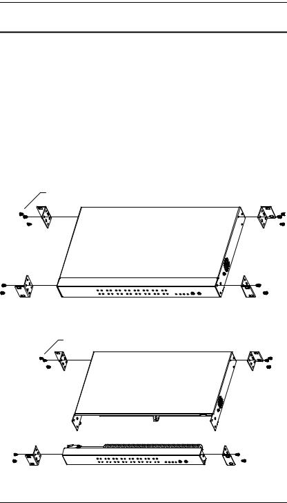
Rack Mounting
The KN9108 / KN9116 can be mounted in a 1U system rack. For convenience and flexibility, the mounting brackets can screw into either the front or the back of the unit so that it can attach to the front or the back of the rack. Alternately, the front and rear modules can be separated so that the front module can be mounted at the front of the rack while the rear module is mounted at the rear. To rack mount the unit do the following:
1.Remove the four screws that attach the front and rear modules.
2.Using the screws provided with the rack mounting kit, screw the rack mounting brackets into the sides of the unit at the front and/or the rear, as shown in the diagrams below.
3.Slide the unit into the rack and secure it to the rack.
Phillips hex head
M3 x 8
Phillips hex head
M3 x 8
12
Chapter 2. Hardware Setup
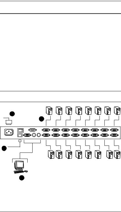
Installation
Installing your new KN9108 / KN9116 KVM Switch involves the following six steps (refer to the diagram below).
1.Plug your keyboard, mouse, and monitor into the unit's Console Ports.
2.Use KVM cable sets (see Cables, page 5), to connect any available CPU Port to the Keyboard, Video and Mouse ports of the computer you are installing.
3.Plug the LAN, WAN or Internet cable into the KN9108 / KN9116's RJ-45 socket.
4.Plug the female end of the power cord into the KN9108 / KN9116's Power Socket; plug the male end into an AC power source.
5.Turn on the power to the KN9108 / KN9116.
6.After the KN9108 / KN9116 is powered up, turn on the computers.
Note: Although the KN9116 is pictured in the diagram, the installation process is the same for the KN9108.
4
2
3
1
13

KN9108 / KN9116 User Manual
Hot Plugging
The KN9108 / KN9116 supports hot plugging - components can be removed and added back into the installation by unplugging and replugging their cables from the ports without the need to shut the unit down.
If you change computer positions, however, in order for the OSD menus to correspond to the CPU port changes, you must manually edit the Port Names for the OSD to reflect the new Port information. See Port Names, page 20, for details.
Note: If the computer's operating system does not support hot plugging, this function may not work properly.
Port ID Numbering
Each CPU port on the installation is assigned a unique Port ID. The Port ID is a two digit number which reflects the CPU Port on the KN9108 / KN9116 that the computer is connected to. Port numbers from 1 - 9 are padded with a preceding zero, so they become 01 - 09.
For example, a computer attached to Port 6 would have a Port ID of: 06.
Powering Off and Restarting
If it becomes necessary to power off the KN9108 / KN9116, or if the switch loses power and needs to be restarted, wait 10 seconds before powering it back on. The computers should not be affected by this, but if any of them should fail, simply restart the affected computers.
Port Selection
Port Selection is accomplished either by entering Hotkey combinations from the keyboard, or by means of the OSD (On Screen Display). Hotkey Port Selection is discussed in the next chapter; OSD Operation is discussed in detail in Chapter 5, and Chapter 6.
14
Chapter 3
Administration
Overview
The OSD's Administration page lets the Administrator (and users with administration permission - see User Management, page 24) configure and control the overall operations of the KN9108 / KN9116. The Administration tab is disabled (grayed out) for users who do not have administration permission.
The Local Console
Once the KN9108 / KN9116 has been installed, the next step that the Administrator needs to perform is to set up the unit for user operation. The most convenient way to do this for the first time is from the local console.
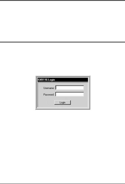
After the local console has been connected and the KN9108 / KN9116 turned on, a login prompt appears on the console monitor:
Since this is the first time you are logging in, use the default Username: administrator; and the default Password: password. For security purposes, we strongly recommend that you use the User Management function (see page 24) to remove these and give yourself a unique Username and Password with the appropriate permissions.
15
KN9108 / KN9116 User Manual
After you successfully log in, the Local Console OSD appears:
There are four buttons on the title bar at the top right. They are described below starting from the left and moving to the right:
Screen View: toggles the display between full screen and window view.
Transparent: clicking this button causes the OSD display to become semi-transparent, allowing whatever the OSD screen is covering to show through. Clicking the button again causes the OSD display to revert back to normal opacity.
Note: 1. 1.It is recommend that you set the refresh rate of the monitor higher than 75Hz before using this feature.
2.When the transparent feature is enabled, if you switch to a null port the feature will be disabled.
Log out: clicking this button (or pressing F8) closes the OSD display and logs you out of the session.
Close: clicking this button closes the OSD display but does not log you out of the session. You can bring the display back with the OSD hotkeys (see
OSD Hotkey, page 72).
The OSD consists of four pages, each with a specific set of functions: Main, Configuration, Administration, and Log.
16

Chapter 3. Administration
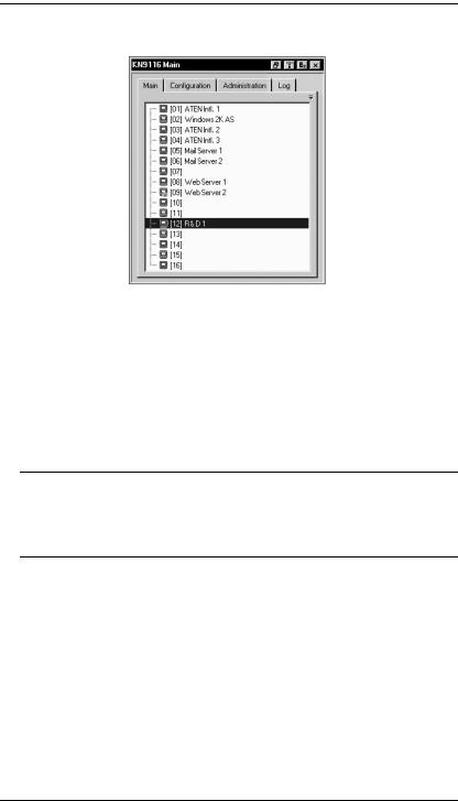
The Main Page
The Main page governs port access. Selecting a port and double-clicking it switches you to the device on that port.
A monitor icon is in front of the port number. The monitor icon is green for ports that have devices connected to them that are powered on; otherwise, it is gray.
If a port has been specified as a Quick View port (see below), an eye icon is displayed along with the monitor icon to indicate so.
In addition to using this page to select ports to switch to, the administrator can also use this page to enable/disable Quick View status for selected ports, and to create, modify, or delete names for each of the ports. The following sections describe how to enable Quick View and how to assign names to ports.
Quick View Ports
Selecting certain ports as Quick View ports is a way of limiting which ports are included when the KN9108 / KN9116 is in Auto Scan mode. If the KN9108 / KN9116 is configured to only auto scan ports that have Quick View status (see Scan Select, page 72), designating a port as a Quick View port in this dialog box means that it will be included when auto scanning is in effect.
The spacebar toggles a port's Quick View status. To select/deselect a port, highlight it and press the spacebar. When a port has been selected as a Quick View port, an eye icon displays in the port icon column to indicate so. When a port isn't selected, there are no eye icons in the column.
17
KN9108 / KN9116 User Manual
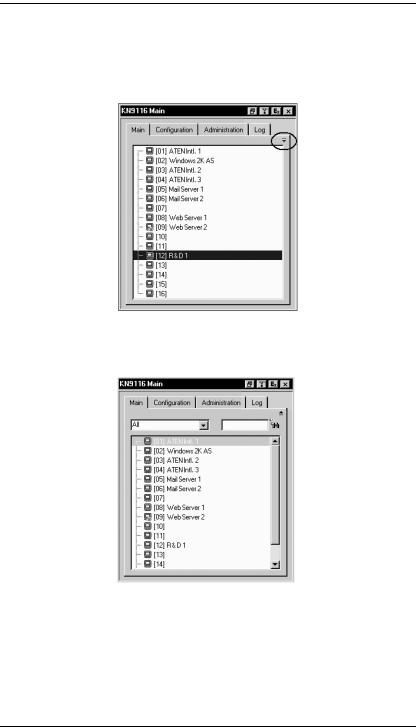
The List Function
The List Function lets you broaden or narrow the scope of which ports the OSD displays (lists) in the Main Screen. To invoke the List Function, click the arrow at the upper right corner of the screen, or press [F3]:
The screen changes to allow you to choose the ports that will be listed:
18
Chapter 3. Administration
The drop down list on the left offers four fixed choices as shown in the table below:
Choice |
Meaning |
|
|
All |
Lists all of the ports on the installation. |
|
|
Powered On |
Lists only the ports that have their attached devices powered on. |
|
|
Quick View |
Lists only the ports that have been selected as Quick View ports |
|
(see Quick View Ports, page 17) |
|
|
Quick View + |
Lists only the ports that have been selected as Quick View Ports |
Powered On |
(see Quick View Ports, page 17), and that have their attached |
|
computers Powered On. |
|
|
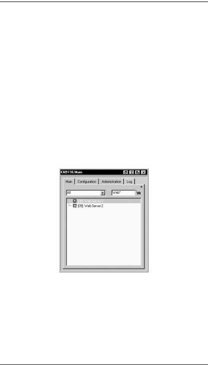
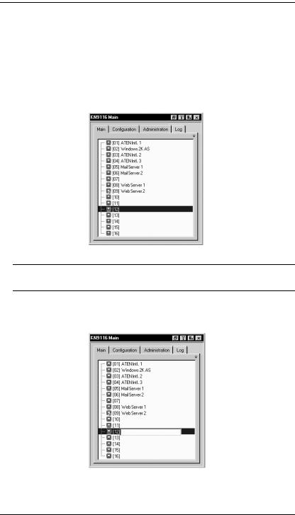
The text input box on the right allows you to key in a port name so that only port names that match what you key in show up in the List. Wildcards (? and *) are acceptable, so that more than one port can show up in the list. For example, if you key in Web*, both Web Server 1 and Web Server 2 would show up in the list, as shown in the screen shot below:
After you key in your string, either click the binoculars icons to the right of the box, or press [Enter].
To go back to the default view, erase the string and either click the binoculars to the right of the box, or press [Enter].
To dismiss the List function, click the arrow or press [F3].
19
KN9108 / KN9116 User Manual
Port Names
To help remember which computer is attached to a particular port, every port can be given a name. This field allows the Administrator to create, modify, or delete port names. To configure a port name:
1.Click once on the port you want to edit, wait one second and then click again. (Alternately, use the up and down arrow keys to move the highlight bar to the port, and then press the F2 function key.)
Note: This is not a double-click. It involves two separate clicks. A doubleclick will switch you to the device attached to the port.
After a second or two, the bar changes to provide you with a text input box:
20
Loading...